

Page 1
2211813
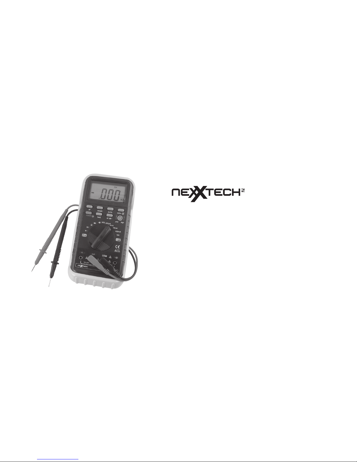
DUAL DISPLAY 29 AUTO RANGE
DIGITAL MULTIMETER
OPERATOR’S MANUAL
Page 2

CONTENTS PAGE
1. Safety Information ............................................................................. 1
1.1 Introduction ............................................................................. 1
1.2 Usage ............................................................................. 2
1.3 Symbols ............................................................................. 3
1.4 Maintenance ............................................................................. 4
2. Description ............................................................................. 5-10
3. Operating Instructions ............................................................................. 11
3.1 Measuring Voltage ............................................................................. 11
3.2 Measuring Current ............................................................................. 11
3.3 Measuring Resistance ............................................................................. 12
3.4 Continuity Test ............................................................................. 13
3.5 Testing Diodes ............................................................................. 13
3.6 Testing Transistors ............................................................................. 14
Page 3

4. Specifications ............................................................................. 14
4.1 General Specifications ............................................................................. 15
4.2 DC Voltage ............................................................................. 16
4.3 AC Voltage ............................................................................. 17
4.4 DC Current ............................................................................. 18
4.5 AC Current ............................................................................. 19
4.6 Resistance ............................................................................. 20
4.7 Diode ............................................................................. 21
4.8 Audible Continuity ............................................................................. 21
4.9 Transistor ............................................................................. 21
5. Accessories ............................................................................. 22
5.1 Supplied with the multimeter ............................................................................. 22
5.2 How to use the holster ............................................................................. 22
6. Battery and Fuse Replacement ............................................................................. 24
Page 4

1. SAFETY INFORMATION
This multimeter has been designed according to IEC-1010 concerning electronic measuring
instruments with an overvoltage category (CAT II) and pollution 2.
Follow all safety and operating instructions to ensure that the meter is used safely and is kept in
good operating condition.
1.1 INTRODUCTION
• When using the meter, the user must observe all normal safety rules concerning:
- Protection against the dangers of electrical current.
- Protection of the meter against misuse.
• Full compliance with safety standards can be guaranteed only if used with test leads supplied. If
necessary, they must be replaced with the same model or same electric ratings. Measuring leads
must be in good condition.
-1-
Page 5

1.2 USAGE
• Never exceed the protection limit values indicated in specifications for each range of
measurement.
• When the meter is linked to a measurement circuit, do not touch unused terminals.
• When the value scale to be measured is unknown beforehand, set the range selector at the
highest position.
• Before rotating the range selector to change functions, disconnect test leads from the circuit under
test.
• When carrying out measurements on TV or switching power circuits, always remember that there
may be high amplitude voltage pulses at test points which can damage the meter.
• Never perform resistance measurements on live circuits.
• Always be careful when working with voltages above 60V dc or 30V ac rms. Keep fingers behind
the probe barriers while measuring.
-2-
Page 6

1.3 SYMBOLS
Important safety information, refer to the operating manual.
Dangerous voltage may be present.
Earth ground.
Double insulation (Protection class II).
-3-
!
Page 7

1.4 MAINTENANCE
• Before opening the meter, always disconnect test leads from all sources of electric
current.
• For continue protection against fire, replace fuse only with the specified voltage and current
ratings:
F1: F 500mA/250V F2: F 10A/250A
• If any faults or abnormalities are observed, the meter cannot be used and it has to be checked out.
• Never use the meter unless the back cover is in place and fastened fully.
• To clean the meter, use a damp cloth and mild detergent only, do not use abrasives or solvents on it.
-4-
Page 8

2. DESCRIPTION
This meter is an auto ranging professional measuring instrument with 33/4 digit LCD, capable of
performing functions:
- DC voltage measurement (Auto Ranging)
- AC voltage measurement (Auto Ranging)
- DC current measurement
- AC current measurement
- Resistance measurement (Auto Ranging)
- Diode test
- Transistor test
- Audible continuity test
-5-
Page 9

1-7. Function Buttons
8. Transistor Testing Socket
9. Rotary Switch
10. V/Ω Input Jack
11. COM Input Jack
12. mA Input Jack
13. A Input Jack
-6-
Page 10

UP (Range Selecting Button)
When this button is pushed, voltage ranges will change as:
4V 40V 400V 1000V 400mV
Or resistance ranges change as:
400Ω 4kΩ 40kΩ 400kΩ 4MΩ 40MΩ
DOWN (Range Selecting Button)
When this button is pushed, voltage ranges will change as:
4V 400mV 1000V 400V 40V
Or resistance ranges change as:
400Ω 40MΩ 4MΩ 400kΩ 40kΩ 4kΩ
-7-
Page 11

AUTO (Auto Ranging Button)
When this button is pushed in manual ranging mode, the meter will return to be in auto ranging
mode immediately and “AUTO” symbol will appear on the top of the LCD.
DATA-H (Data Hold Button)
When this button is pushed, the display will keep the last reading and “D-H” symbol will appear on
the LCD until pushing it again.
A /A~ (DCA/ACA Selecting Button)
This button is used to select ACA or DCA measuring mode.
i
(Silence Selecting Button)
When this button is pushed, the built-in buzzer will not sound except in continuity testing until
pushing this button again.
-8-
Page 12

POWER (Power ON-OFF Button)
This button is used to turn the meter ON or OFF. In Order to extend the battery life, an Auto Power
OFF function is provided. If no key-inputs happen around 30 minutes, the meter will be turned off
automatically. To turn the meter on again, just push this button once.
ROTARY SWITCH
This switch is used to select functions.
INPUT JACKS
This meter has four input jacks that are protected against overload to the limits. During use, connect
the black test lead to the COM jack and the red test lead as shown below:
-9-
Page 13

Function Red Lead Connection Input limits
DCV / ACV V / Ω 1000V DC or 750V rms AC
Ω V / Ω 250V DC or rms AC
V / Ω 250V DC or rms AC
i V / Ω 250V DC or rms AC
µA / mA mA 500mA DC or rms AC
A A 10A DC or rms AC
µA / mA and A ranges are protected by fuses
-10-
Page 14

3. OPERATING INSTRUCTIONS
3.1 MEASURING VOLTAGE
1. Connect the black test to the COM jack and the red test lead to the V/Ω jack.
2. Set the function switch at V or V ~ range to be used and connect test leads across the source
or load under measurement.
3. Read LCD display. The polarity of red connection will be indicated when making a DC
measurement.
3.2 MEASURING CURRENT
1. Connect the black test lead to the COM jack and the red test lead to the mA jack for a maximum
of 500mA. For a maximum of 10A, move the red lead to the A jack.
2. Set the function switch at µA, mA or A range to be used and push / ~ button to select DCA of
ACA measuring mode.
-11-
Page 15

3. Connect test leads in series with the load in which the current is to be measured.
4. Read LCD display. The polarity of red lead connection will be indicated when making a DC
measurement.
3.3 MEASURING RESISTANCE
1. Connect the black test lead to the COM jack and the red test lead to the V/Ω jack. (NOTE: The
polarity of the red lead connection is positive “+”)
2. Set the function switch at Ω range to be used and connect test leads across the resistance under
measurement.
NOTE:
1. For resistance above 1MΩ, the meter may take a few seconds to stabilize reading. This is
normal for high resistance measuring.
2. When the input is not connected, i.e. at open circuit, the figure “OL” will be displayed for the over
range condition.
-12-
Page 16

3. When checking in-circuit resistance, be sure the circuit under test has all power removed and all
capacitors fully discharged.
3.4 CONTINUITY TEST
1. Connect the black test lead to the COM jack and the red test lead to the V/Ω jack. (NOTE: The
polarity of red lead connection is positive “+”)
2. Set the function switch at i position and connect test leads to two points of the circuit under
measurement. If continuity exists (i.e., the resistance is lower than 50Ω), built-in buzzer will
sound.
3.5 TESTING DIODES
1. Connect the black test lead to the COM jack and the red test lead to the V/Ω JACK. (NOTE: The
polarity of the red lead connection is positive “+”)
2. Set the function switch at position.
-13-
Page 17

3. Connect the red lead to the anode of the diode to be tested and the black lead to the cathode.
Read LCD display to get the forward voltage drop of the diode under testing.
3.6 TESTING TRANSISTORS
1. Set the function switch at hFE position.
2. Identify whether the transistor NPN or PNP type and locate emitter, base and collector lead.
Insert Ieads of the transistor to be tested into proper holes of the testing socket on the front panel.
3. LCD display will show the approximate hFE value.
4. SPECIFICATIONS
Accuracy is specified for a period of one year after calibration and at 64°F to 82°F (18°C to 28°C)
with relative humidity to 80%.
-14-
Page 18

4.1 GENERAL SPECIFICATIONS
Max. Voltage Between Terminals and Earth Ground 1000V dc or 750V rms ac (sine)
Fuse Protection µA, mA: F 500mA/250V A:F 10A/250V
Power Supply 9V NEDA1604 6F22 006P
Display LCD, 3999 counts max., updates 2-3/sec
Measurement Method Dual slope integration A/D converter
Ranging Method Auto/Manual
Over range Indication “OL” displayed
Polarity Indication “ - ” displayed automatically
Low Battery Indication “BATT” displayed
Operating Temperature 32°F to 104°F (0°C to 40°C)
Storage Temperature 10°F to 122°F (-10°C to 50°C)
Dimension 3.5 x 7.4 x 1.2 inch (91 x 189 x 31.5 mm)
Weight 11oz (310g) (Including battery)
-15-
Page 19

Range Resolution Accuracy
400mV 0.1mV ± 0.8% of rdg ± 2 digits
4V 1mV ± 0.5% of rdg ± 2 digits
40V 10mV ± 0.5% of rdg ± 2 digits
400V 0.1V ± 0.5% of rdg ± 2 digits
1000V 1V ± 0.8% of rdg ± 2 digits
4.2 DC VOLTAGE
Input Impedance: 10MΩ, more than 1.00MΩ at 400mV range.
-16-
Page 20

4.3 AC VOLTAGE
Input Impedance: 10MΩ
Frequency Range: 40 to 400Hz
Response: Average, calibrated in rms of sine wave.
-17-
Range Resolution Accuracy
400mV 0.1mV ------ 4V 1mV ± 0.6% of rdg ± 0.2% of full scale ± 3 digits
40V 10mV ± 0.6% of rdg ± 0.2% of full scale ± 3 digits
400V 0.1V ± 0.6% of rdg ± 0.2% of full scale ± 3 digits
750V 1V ± 1.2% of rdg ± 3 digits
Page 21

4.4 DC CURRENT
Overload Protection: F 500mA fuse for µA and mA ranges, F 10A fuse for A range.
-18-
Range Resolution Accuracy
400
µV 0.1µA ± 0.8% of rdg ± 2 digits
4mA 1
µA ± 0.8% of rdg ± 2 digits
40mA 10
µA ± 0.8% of rdg ± 2 digits
400mA 0.1mA ± 1.2% of rdg ± 2 digits
10A 1mA ± 2.0% of rdg ± 5 digits
Page 22

4.5 AC CURRENT
Overload Protection: F 500mA fuse for
u A and mA ranges, F 10A fuse for A range.
Frequency Range: 40 to 400Hz
Response: Average, calibrated in rms of sine wave.
-19-
Range Resolution Accuracy
400
u A (0-200 u A) 0.1 u A ± 0.8% of rdg ± 0.4% of full scale ± 3 digits
400
u A (201-300 u A) 0.1 u A ± 2.5% of rdg ± 0.4% of full scale ± 3 digits
400
u A (301-400 u A) 0.1 u A ± 8.0% of rdg ± 0.4% of full scale ± 3 digits
4mA 1
u A ± 0.8% of rdg ± 0.4% of full scale ± 3 digits
40mA 10
u A ± 0.8% of rdg ± 0.4% of full scale ± 3 digits
400mA 0.1mA ± 1.2% of rdg ± 0.4% of full scale ± 3 digits
10A 10mA ± 3.0% of rdg ± 5 digits
Page 23

4.6 RESISTANCE
Maximum Open Circuit Voltage: 3.2V
-20-
Range Resolution Accuracy
400
Ω 0.1Ω ± 0.8% of rdg ± 3 digits
4kΩ 1
Ω ± 0.8% of rdg ± 1 digits
40kΩ 10
Ω ± 0.8% of rdg ± 1 digits
400kΩ 100Ω ± 0.8% of rdg ± 1 digits
4MΩ 1kΩ ± 0.8% of rdg ± 1 digits
40MΩ 10kΩ ± 1.2% of rdg ± 2 digits
Page 24

4.7 DIODE
4.8 AUDIBLE CONTINUITY
4.9 TRANSISTOR
-21-
Function Resolution Test Current Open Circuit Voltage
1mV 25
µA 3.0V
Function Description
i
Built in buzzer will sound, if resistance is lower than 50Ω.
Function Range Base Current Vce
h
FE 1 to 1000 10µA 3.0V
Page 25

5. ACCESSORIES
5.1 SUPPLIED WITH THE MULTIMETER
Test Leads Electric Ratings 1500V, 10A MASTECH HYTL-060
Operating Manual HYS004241
Holster HYHT-60
5.2 HOW TO USE THE HOLSTER
The holster can be used to protect the meter as well as providing a stand to improve viewing
angle. The following figure shows how to use the holster to:
a. Support the meter with a standard angle.
-22-
Page 26

b. Support the meter with a shallow angle using the small stand.
c. Hang the meter on the wall using the small stand.
Change the viewing angle by using the large stand and removing small stand.
d. Holds test leads.
-23-
Page 27

6. BATTERY AND FUSE REPLACEMENT
If the sign “BATT” appears on the LCD display, it indicates that the battery should be replaced.
Remove screws on the back cover and open the case. Replace the exhausted battery with a new
battery.
Fuses rarely need replacement and blow usually as a result of incorrect use. Open the case as
mentioned above and take the Printed Circuit Board assembly out of the case. Replace the blown
fuse with a proper rated fuse below.
WARNING
Before attempting to open the open case, be sure that it is disconnected to avoid electric shock
hazard.
For protection against fire, replace fuses only with specified ratings:
F1: F 500mA/250V F2: F 10A/250V
-24-
!
Page 28

LIMITED WARRANTY
Who is Providing This Warranty?
• Orbyx Electronics, LLC (”Orbyx”), as the distributor of
this Nexxtech
TM
product (your “Product”).
What Does This Warranty Cover?
• This warranty covers defects in materials or
workmanship in your Product under normal use and
conditions.
What is the Period of Coverage?
• This warranty covers your Product for 90 days from the
original purchase date.
Who Is Covered?
• This warranty covers the original consumer purchaser.
Coverage terminates if you sell or otherwise transfer
your Product.
What Will We Do To Correct Problems?
• We will repair your Product or replace your Product with
a new or reconditioned equivalent product, at our option.
How Do You Get Service?
• Call Orbyx TOLL FREE at 1-866-363-3059 for
instructions for obtaining warranty service from Orbyx’s
authorized service providers.
• Or, return your Product directly to the retail store from
which you purchased the Product.
• When you obtain service for your Product, you must
provide a purchase receipt (or other proof of the original
purchase date) and a description of the defect(s).
What Does This Warranty Not Cover?
• This warranty DOES NOT COVER:
• damage due to misuse, abuse, alteration, unauthorized
repair, or accident (such as improper electrical current);
• damage due to “acts of God” (such as lightning) or other
contingencies beyond our control;
• cosmetic damage;
• externally generated static, signal reception or antenna
problems not caused by your Product; or batteries.
• This warranty also DOES NOT COVER, and in no case
will we be liable for, any incidental damages (such as
transportation costs to and from an authorized service
provider, or loss of time) or consequential damages
(such as costs of repairing or replacing other property
which is damaged, including tapes, discs, speakers not
included with your Product or other accessories, or
external electrical systems) resulting from the use of
your Product. Some states do not allow the exclusion or
limitation of incidental or consequential damages, so the
above limitation or exclusion may not apply to you.
Page 29

• Defacing the serial number, or using your Product for
commercial or institutional purposes, voids this warranty.
Are There Other Warranties?
• There are no express warranties other than those
expressed herein. Neither the sales personnel nor any
other person is authorized to make any other warranties or
to extend the duration of any warranties.
• ANY IMPLIED WARRANTIES, INCLUDING ANY IMPLIED
WARRANTY OF MERCHANTABILITY (AN UNWRITTEN
WARRANTY THAT A PRODUCT IS FIT FOR ORDINARY
USE), ARE LIMITED TO 90 DAYS. Some states do not
allow limitations on how long an implied warranty lasts, so
the above limitation may not apply to you.
How Does State Law Apply?
• This warranty gives you specific legal rights, and you may
also have other rights which vary from state to state.
ORBYX ELECTRONICS WARRANTY
ORBYX Electronics warrants that this product will be free from
defects in materials and workmanship for a period of ninety (90)
days from the date of purchase. Within this period, simply take
the product and your proof of purchase to any ORBYX
Electronics store or dealer and the product will be repaired
without charge for parts and labour. ORBYX Electronics
reserves the right to charge for transportation. Any product
which has been subject to misuse or accidental damage is
excluded from this warranty.
This warranty is only applicable to a product purchased through
ORBYX Electronics' company owned stores and dealers and to
a product that is presented for repair in a country where
ORBYX Electronics offers the product for sale. While this
warranty does not confer any legal rights other than those set
out above, you may have additional statutory rights which will
vary under the laws of the various countries, states, province
and other governmental entities in which ORBYX Electronics
operates. This warranty is subject to all statutory rights you may
have in the country of purchase.
LIMITED WARRANTY
Limited Warranty/Garantie Limitée
U.S.A & Canada
© 2005 ORBYX Electronics. All Rig hts Reserved.
Distributed exclusively in
the U.S. by
Orbyx Electronics, LLC
501 South Cheryl Lane,
Walnut, CA 91789
Imported in Canada
for/Importé au Canada pour
Orbyx Electronics,
Concord, Canada, L4K 4M3
Manufactured in China
For product support please
contact
www.orbyxelectronics.com
or 1-866-363-3059
 Loading...