

Page 1
Nexxt Solutions - IP Camera Centralization Management Software
Page 2
Nexxt Solutions - IP Cameras XPY 500-510-520 Series
Chapter 1
User manual
1. Package contents
Open the box and make sure all items listed below are included:
• Integrated wireless IP camera
• AC power adaptor
• Quick installation guide
• CD-ROM (IPC monitor client and search application)
• Network cable
• Mounting bracket and hardware
• Wireless antenna (only applicable to 510 and 520)
Product overview
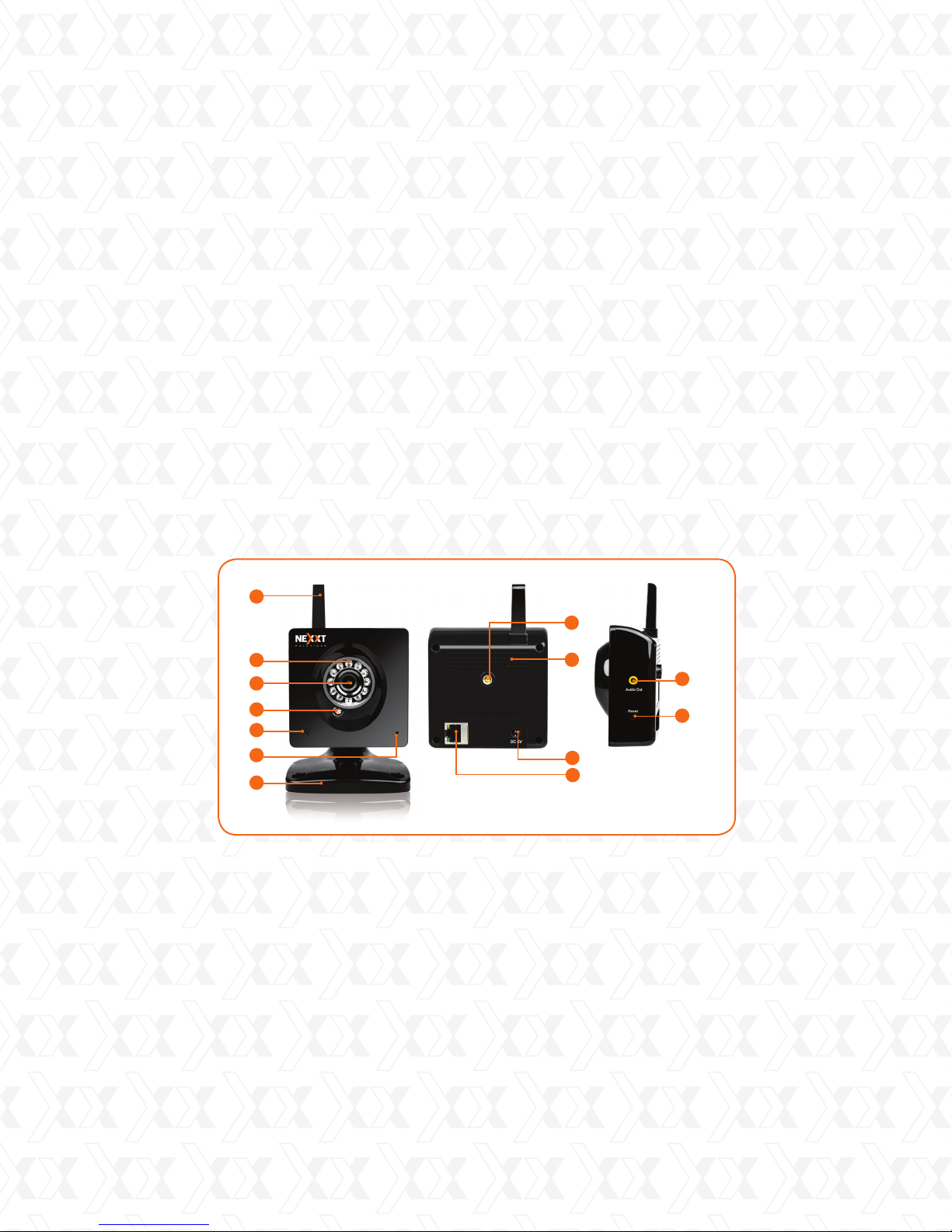
XPY 500
1
2
3
4
5
6
7
1 pc
1 pc
1 pc
1 pc
1 pc
1 set
1 pc
8
9
12
13
11
10
Built-in wireless antenna
1.
Night vision LEDs
2.
Lens
3.
Light sensor
4.
Built-in microphone
5.
Status indicator light
6.
Mounting base with articulating arm
7.
Camera mount socket
8.
Heat sink
9.
Network port (RJ45)
10.
5V DC in
11.
Audio output
12.
Reset button
13.
2
Page 3
Nexxt Solutions - IP Cameras XPY 500-510-520 Series
2. Product overview
XPY 510
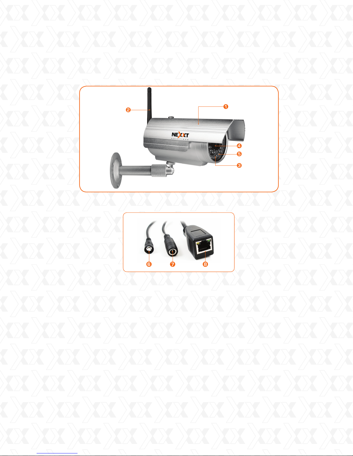
Weatherproof metal casing
1.
Wireless antenna
2.
Night vision LEDs
3.
Lens
4.
Light sensor
5.
Reset button
6.
5V DC in
7.
Network port (RJ45)
8.
3
Page 4
5
6
4
Nexxt Solutions - IP Cameras XPY 500-510-520 Series
3. Product overview
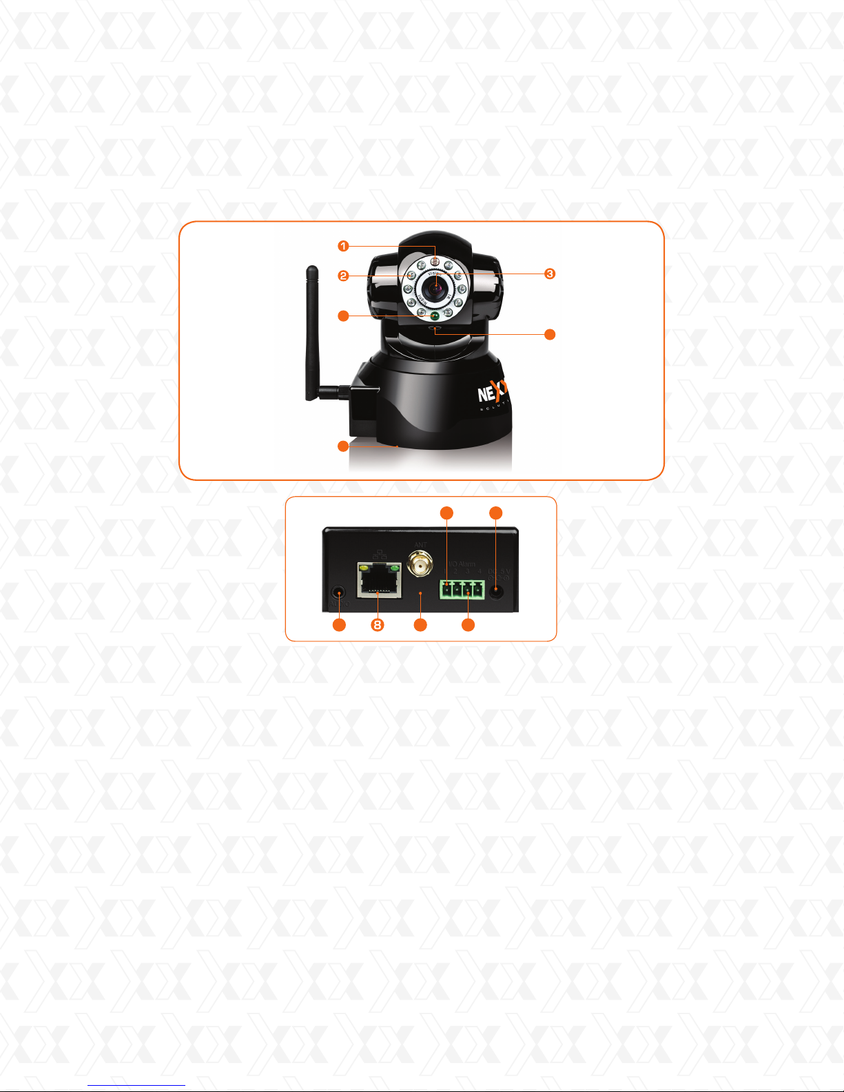
XPY 520
7
Light sensor
1.
Night vision LEDs
2.
Lens
3.
Status indicator light
4.
Built-in microphone
5.
Reset button (on the bottom side of unit)
6.
Audio output
7.
Network port (RJ45)
8.
Wireless antenna jack
9.
Alarm I/O ports
10.
5V DC in
11.
10
9
11
10
4
Page 5
Nexxt Solutions - IP Cameras XPY 500-510-520 Series
4. Basic set up
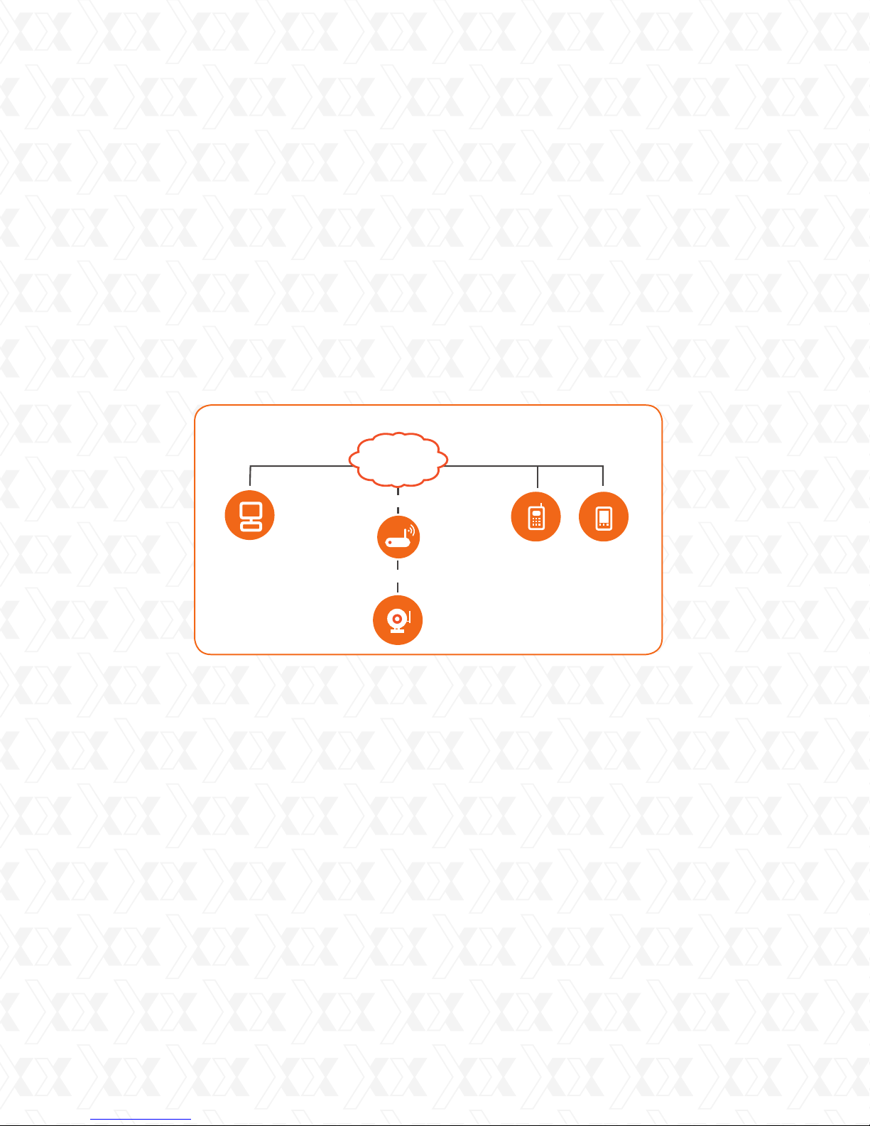
Connection of the IP Camera to the network
Begin by attaching the mounting bracket and the antenna (if applicable) to the device.
1.
Select a mounting position on a wall or ceiling.
2.
Use the screws and wall plugs supplied to fix the mounting base.
3.
Insert the Ethernet cable to the RJ45 interface of the IP camera.
4.
Connect the other end of the network cable to your Ethernet switch, hub or router.
5.
Plug the camera to the wall outlet using the supplied AC adaptor to turn it on.
6.
INTERNET
Internet connection
Modem
Computer
Intranet
IP Camera
Warning: Make sure to use the supplied power adapter for making the connections to the
AC mains. The use of a different adaptor may cause damage to the camera, heat up or
catch re. Any damage caused to the camera by using the incorrect power adaptor will
void the warranty.
Verify that the mains voltage (110V or 220V) and frequency (50 or 60 Hz) of your
location match those specified on the label.
Cellular
Phone
PDA
5
Page 6
Nexxt Solutions - IP Cameras XPY 500-510-520 Series
5. Getting started
System login
A. Installation in a network with the same address range (plug and play mode)
In order to be able to see the camera and congure it, you must rst ensure that the IP
1.
camera is within your network address range.
Note: Nexxt Solutions routers are configured within such parameters.
This means that if your internal network is congured with an IP address using
2.
192.168.0.XXX with subnet mask 255.255.255.0, you will be able to access the camera
directly by entering the default IP address into your web browser (Internet Explorer is the
recommended browser).
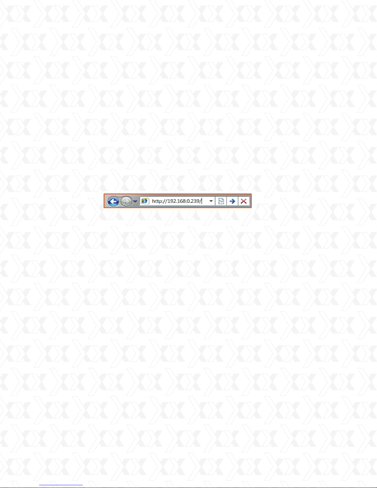
Access the camera using the web interface by typing the device IP address:
192.168.0.239, and then hit enter.
3.
4.
When done, skip to Step 13 to continue.
B.Installation in a network with a different address range (manual setup)
If your internal network is congured based on a different IP address range, you must
1.
change the IP address of the camera to match your network range. In that case, use the
BSearch_en.exe tool located on the supplied CD or on our Nexxt Solutions website.
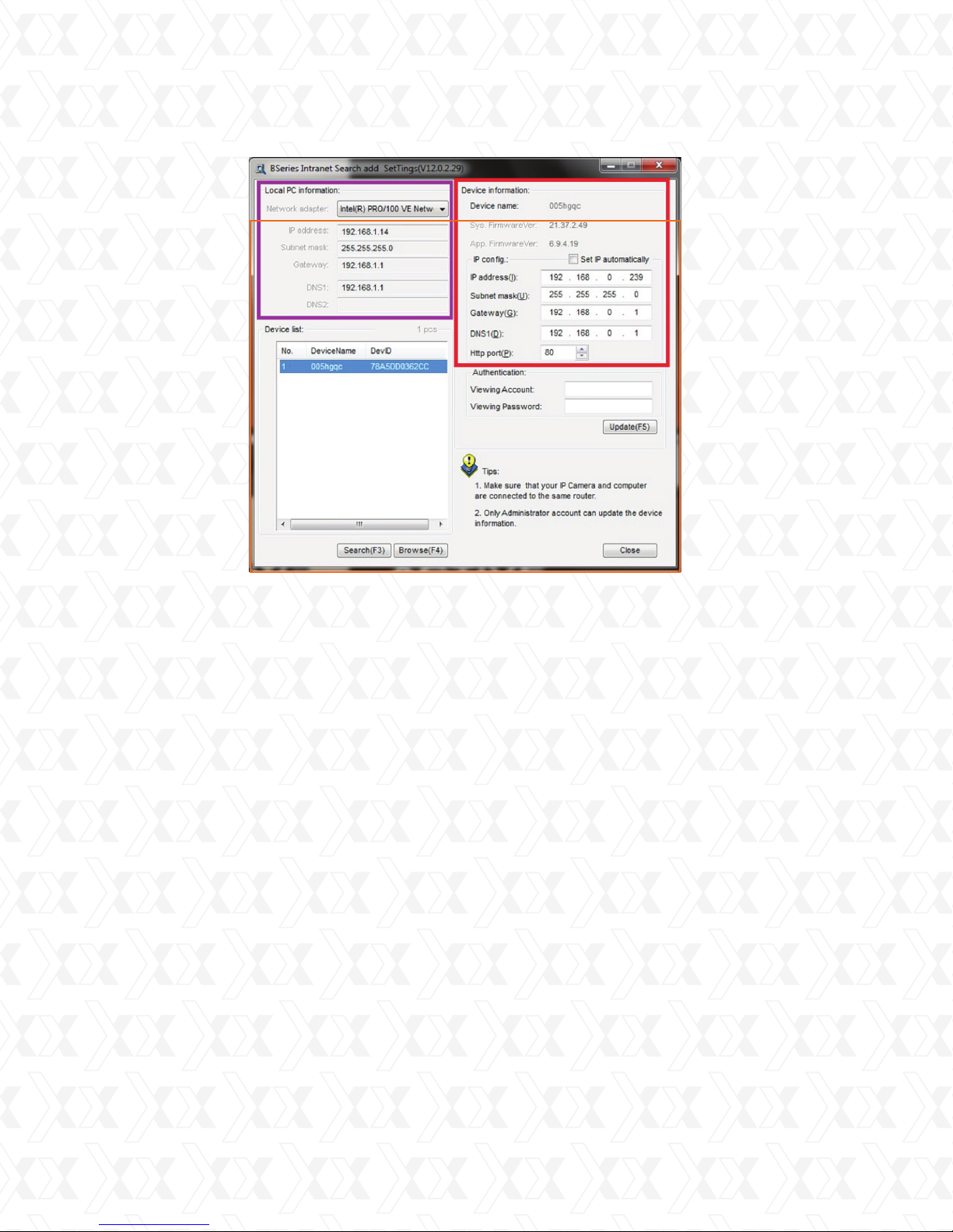
Next, open BSearch_en.exe tool and click on the Search option located near the lower-left
2.
corner of the screen, or simply press F3 on your keyboard.
Under Local PC information, you will nd your PC’s network parameters.
3.
Under Device information, you will nd the default values of the IP camera.
4.
Under Device list, you will nd all the IP cameras detected on your network.
5.
In the example below, you will notice a PC connected to an internal network which is using
6.
an IP address of 192.168.1.14, a Subnet mask of 255.255.255.0, plus a Gateway and
a DNS1 of 192.168.1.1.
6
Page 7
Nexxt Solutions - IP Cameras XPY 500-510-520 Series
In order for you to access the camera successfully in this scenario, the user
7.
change the IP address, Subnet mask, Gateway and DNS to match the network
parameters of the local PC information or network.
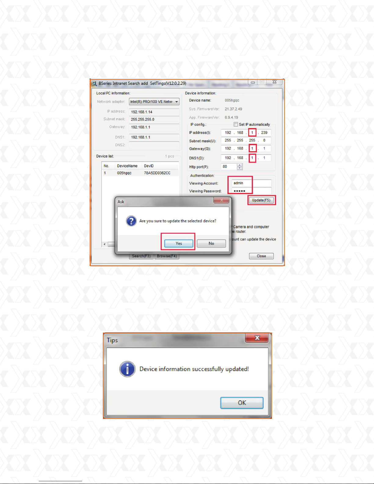
Under Device information, change the IP address to 192.168.1.239, the Subnet
8.
mask to 255.255.255.0 and the Gateway and DNS, to 192.168.1.1.
Note: the IP address must fall within your network range, but outside your DHCP
pool to avoid any IP address conicts on your network. To view or change the Start
and End DHCP address range on your
network, refer to your router’s user manual for instructions.
Next, enter admin under Viewing Account and Viewing Password fields. Once
9.
done, you may click the Update button or press F5 on directly in your keyboard.
The tool will ask you to conrm the changes. Select Yes once prompted.
10.
7
Page 8
Nexxt Solutions - IP Cameras XPY 500-510-520 Series
A notication that the camera has updated the values successfully will be displayed. The
11.
camera will be restarted as soon as you click OK on the message window, as shown below.
8
Page 9
Nexxt Solutions - IP Cameras XPY 500-510-520 Series
Once the camera has completely restarted, you can verify the values to ensure they
12.
are congured correctly. Click on Search or press F3 on your keyboard, in order to
select the camera you have just programmed from the Device list. If all values contained in the Device information section are accurate, click on Browse or press F4
on your keyboard to access the camera directly using Internet Explorer.
NOTE: An alternate configuration method is accomplished using the Set IP automatically option, under the IP config menu. If you choose this option, your router will
assign an IP address automatically using its DHCP address range pool. This type of
conguration is normally not recommended, since the IP address will change every
time the lease time has expired for that specic address under the DHCP server.
This means you must use the search tool every time to determine the new IP
address once expired.
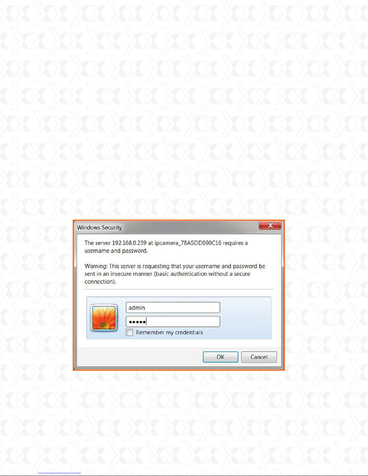
In this step, the Log in window will appear on the screen. By default, the administra-
13.
tor’s username and the password is admin. When done, click OK to continue.
9
Page 10
Nexxt Solutions - IP Cameras XPY 500-510-520 Series
Main User Interface (as seen in Internet Explorer)
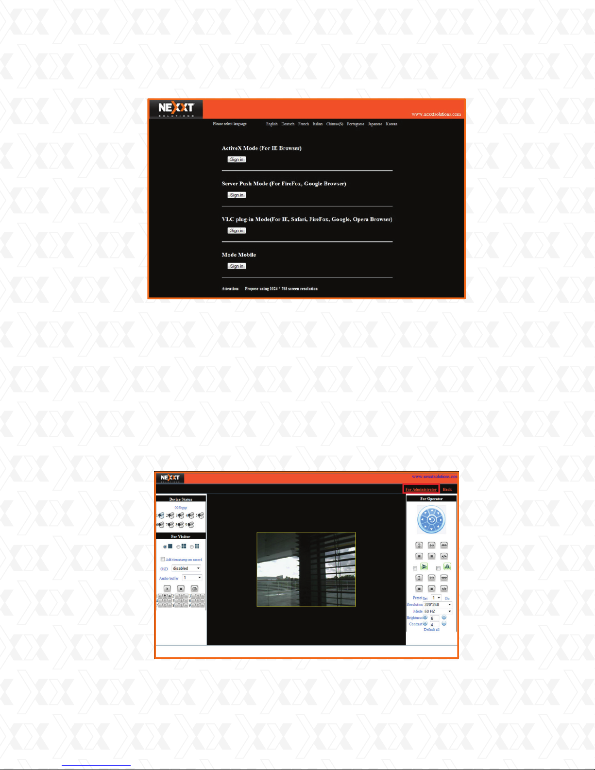
14.
Once the main login interface appears, click on Sign in right below the ActiveX Mode
(For IE Browser) option.
The main user interface provides access to controls and the conguration parameters
of the camera based on the privileges assigned to each particular user. (Please refer
to Section 7 - Camera web interface for a brief overview of the controls available.
For detailed instructions refer to the user manual).
6. Wireless Setup for Xpy500, Xpy510 and Xpy520
Once you log into the camera from previous steps, click on For Administrator option.1.
10
Page 11
Nexxt Solutions - IP Cameras XPY 500-510-520 Series
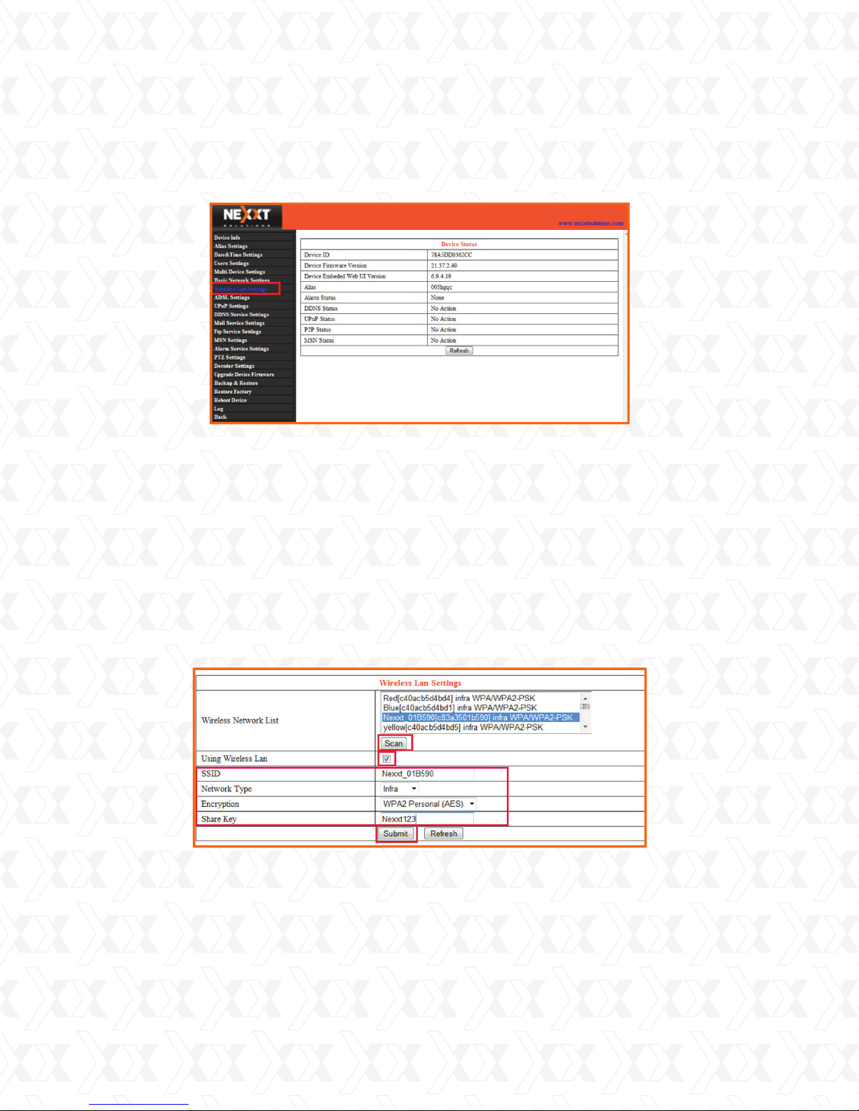
2.
On the left pane, click on Wireless LAN Settings.
3.
On the Wireless LAN Settings menu, click on Scan to search for your Wireless Router
SSID you which are attempting to connect to.
Note: You might need to click on Scan a second or third time for the full list of SSIDs to
show up.
4.
Once you see the SSID of your router, select it from the list and ensure the Using Wireless LAN check box is selected. This will automatically ll in the SSID, Network Type and
Encryption elds which correspond to your router. Verify that these parameters are correct
based on your router congured settings.
Under the Share Key eld, make sure to enter the wireless password from your router.
5.
When done, click on Submit. Once you see the automatic restart message window, disconnect the wired LAN cable.
The camera will automatically connect to your wireless router after the camera has
6.
fully restarted. In the event you are not able to access the camera with the address
you assigned in previous steps, disconnect the power from the camera for several
seconds and then plug it back in. Once the camera boots up, try accessing the camera
once again.
11
Page 12
Nexxt Solutions - IP Cameras XPY 500-510-520 Series
7. Camera web interface
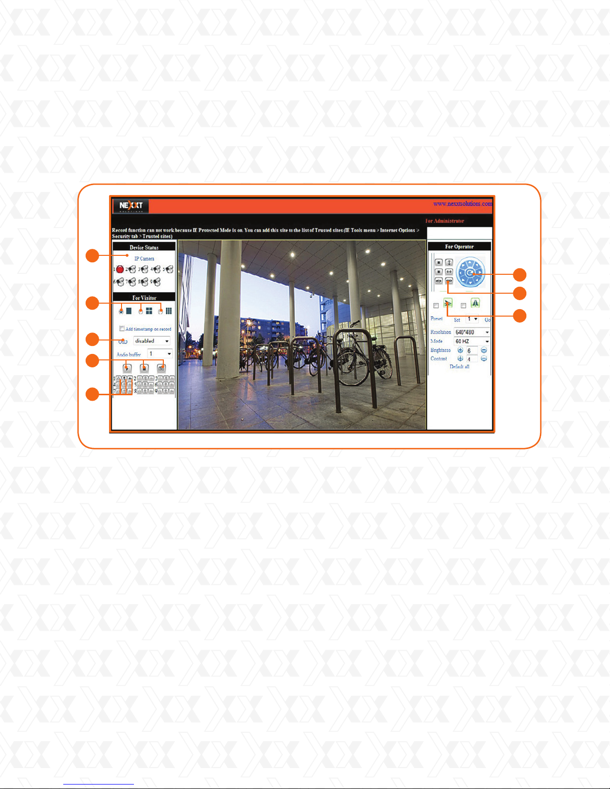
As soon as you log in, the main monitoring page will be displayed, as shown below:
1
6
2
3
4
5
Web browser interface
Status panel: Shows the number of cameras connected on the network.
1.
Views: Full screen, Quad view and Multi-split screen
2.
On Screen Display: shows the date and time on the video
3.
Play, Stop, Snapshot
4.
Audio on/off, Mic, Record
5.
Pan and tilt control buttons
6.
Alarm input on/off (if applicable)
7.
Mirror image
8.
7
8
12
Page 13

Nexxt Solutions - IP Cameras XPY 500-510-520 Series
•
When logging in as an Administrator, the user will have full access to all the controls,
menus and settings available in the device.
•
As an Operator, the user will have access to the main monitoring page, and to a limited
number of parameters associated with the operation of the camera.
•
As a Visitor, the user is only allowed to view the main monitoring page for all the enabled
cameras, having no access to any of the controls or conguration settings on the device.
13
Page 14
Nexxt Solutions - IP Camera Centralization Management Software
Chapter 2
Chapter 2
Free Surveillance Software
IPC monitor
Introduction
The IPC Monitor Client Software is an easy-to-use software designed for surveillance applications with multiple cameras. This software includes PTZ controls (zoom available only in certain
models), recording, alarm notications, in addition to a central management feature that allows
the administration, conguration and access control settings for each individual device.
1. System requirements
CPU: Dual-core CPU
•
RAM: 1GB or above
•
Hard disk: 160GB or above
•
OS: Windows XP or higher
•
Display resolution: 1024x768
•
>
=
2. Installation
Insert the bundled CD to the drive, double click IPCMonitor, a pop-up window will be shown, please
follow the instructions on the window to nish the software installation. After a successful installation,
run the application and the user interface will be displayed.
14
Page 15
Nexxt Solutions - IP Camera Centralization Management Software
3. Device management
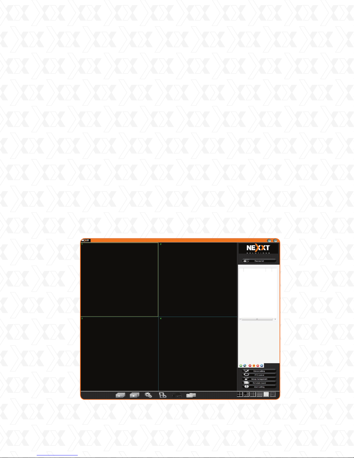
3.1. IPC Monitor Interface
1.
Status panel: shows the number of cameras added to the device.
2.
Views: full screen, Quad view and Multi-split screen.
3.
On Screen display: shows the date and time on the video.
4.
Play and Stop buttons.
5.
Audio on/off, Mic, Record.
6.
Pan, tilt and zoom control buttons.
7.
Alarm input on/off (if applicable).
8.
Device settings: this tree provides a visual representation of all detected devices. It supports a
multi-level structure from which users can connect or disconnect devices in a particular group.
Users can double click on a device to connect it and see the video in the display area, or click
the camera.
9.
PTZ control: direction buttons for controlling the Pan, Tilt and Zoom of the camera. This only
applies to the PTZ camera models.
10.
Group management: set groups of cameras to be displayed in a cycle.
11.
Schedule record: users can appoint a certain period in which the client will start recording.
12.
Alarm settings: the Client software supports various kinds of alarm triggers, alarm events,
and can be used to set an alarm schedule.
13.
Full screen: this view is enabled by right clicking on a channel; double clicking on it also
enlarges the view and returns it to the original size.
14.
Dragging and dropping a channel: click and hold a channel to drag and drop it to another
channel. If the target channel is used, the two video channels will be swapped.
15.
Stop: right click on a channel to stop the video or to view it in full screen.
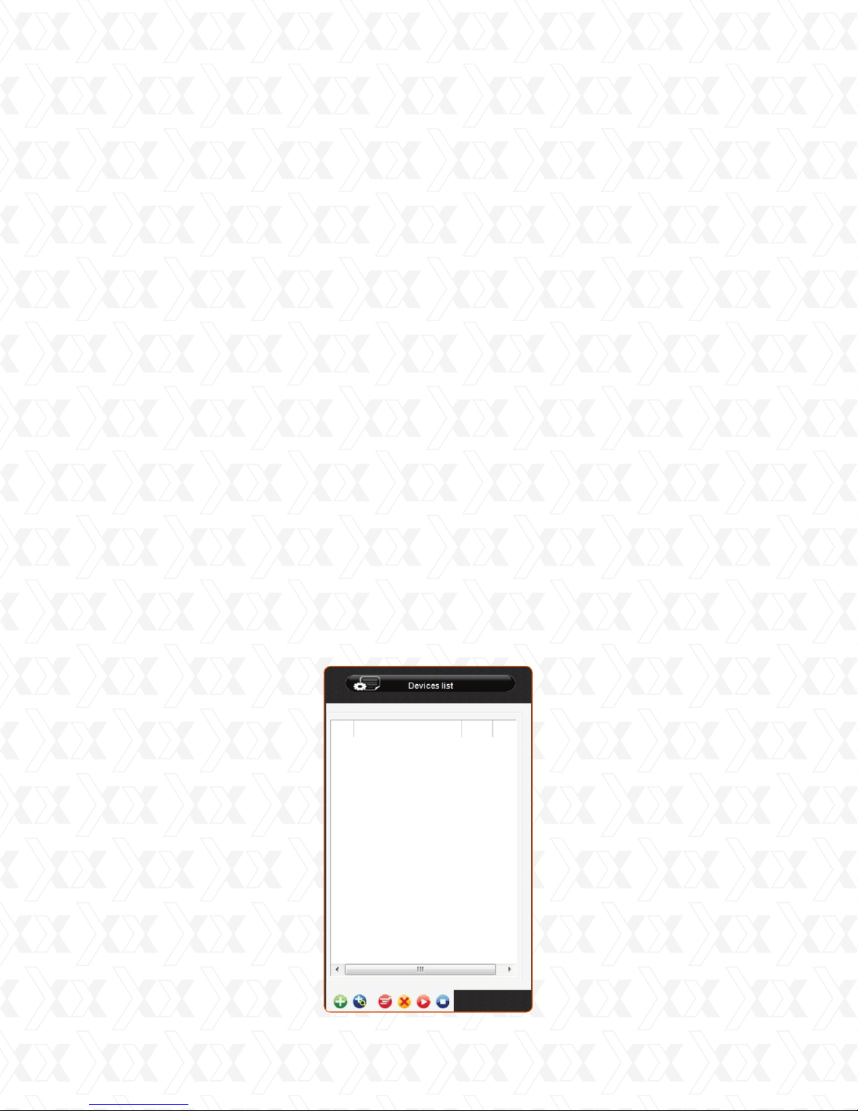
3.2. Device List interface
After installing the client software, we need to add the devices. When running the program, the
device list of the main interface is empty, as shown below:
Device list interface
15
Page 16
Nexxt Solutions - IP Camera Centralization Management Software
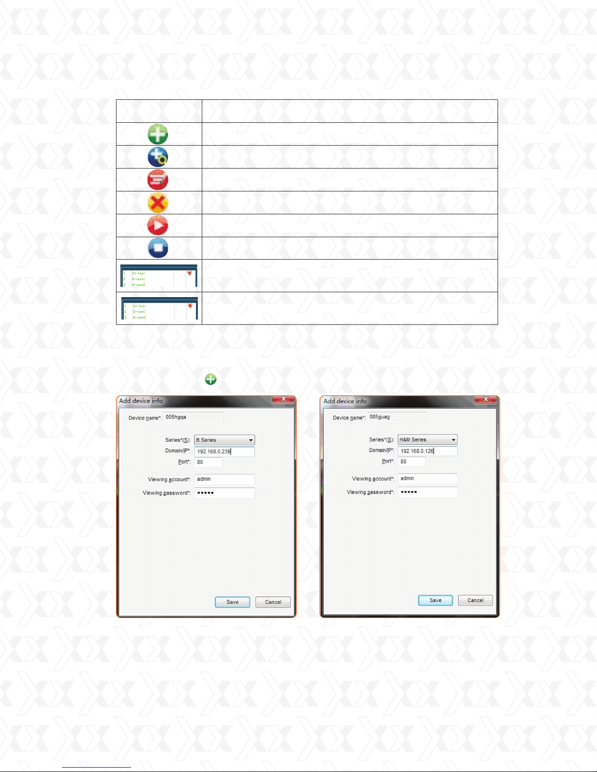
Icon Description
Add a device
Search a device
Modify device information
Deleting a device
Play a video
Stop a video
The device name turns green when playback is in progress
Double click on the Alarm icon to display the alarm log
of the device
4. Adding a device
Click the Add a device icon to open a window like the ones shown below.
B Series (Xpy 500/Xpy 510/Xpy 520) M Series (Xpy 530)
Adding a device
16
Page 17
Nexxt Solutions - IP Camera Centralization Management Software
•
Device name: name assigned to the camera, used to distinguish it from other devices connected.
This name will be displayed on the camera list.
•
Series: B and M series.
•
Domain/IP: enter 192.168.0.239 (for B Series) and 192.168.0.126 (for M Series) which is the
IP address assigned to the camera.
•
Port: the incoming port that has been assigned to the camera, which is 80 by default.
•
Viewing account/password: by default, the administrator’s username and the password is admin.
•
When done, click Save to store your settings.
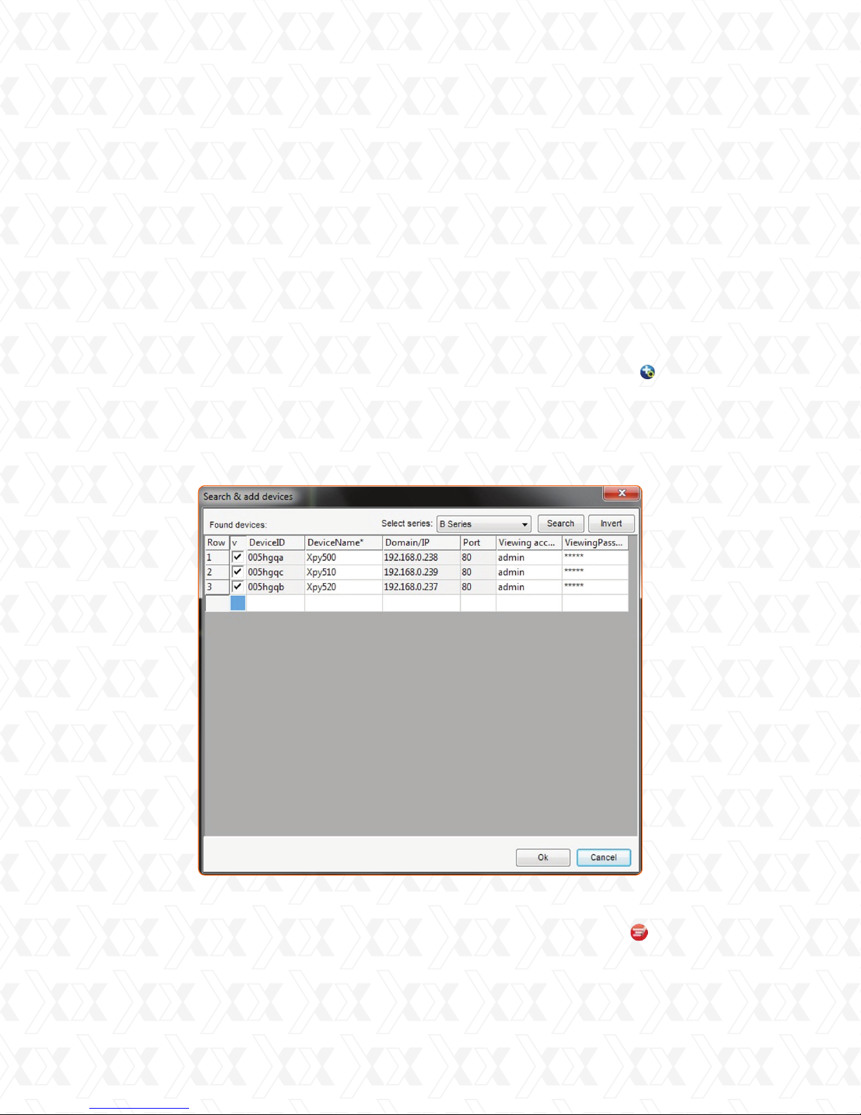
5. Searching and adding devices in the LAN
Go to the Device List Interface bar and click the Search and add devices icon to find the cameras
connected in the LAN. A window will be displayed with information about the cameras that were found.
•
Select the product series and click Search. The found devices will be listed.
•
Select the camera you wish to add. Enter a name followed by Viewing username and password.
•
Click OK to add the selected devices to the list; otherwise click Cancel.
•
Select a camera, on the Device List interface, click the Modify a device icon to edit the
device information.
•
Right click on a selected device to edit or modify such device.
Search and add devices
17
Page 18
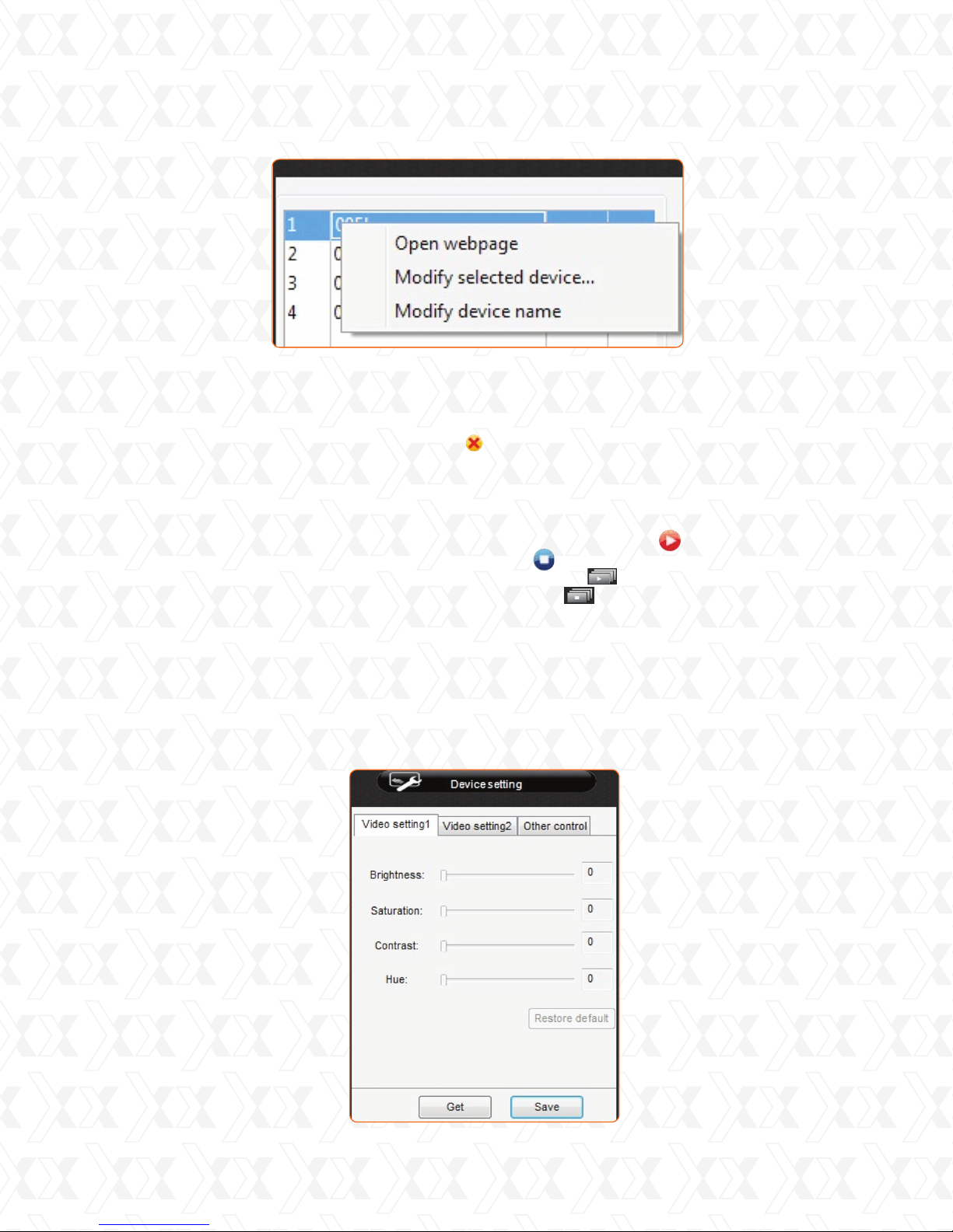
Nexxt Solutions - IP Camera Centralization Management Software
Modify a device name
6. Deleting a device
Select a device and then click the Delete icon to remove it. The Ctrl or Shift key may be
used, if deleting several devices simultaneously.
7. Starting and stopping the video
•
To start a video, select a camera and double click it or press the Play icon.
•
To stop a video, select a camera and press the Stop icon.
•
To start all the cameras simultaneously, select the Start all icon.
To stop all the cameras simultaneously, click the Stop all icon.
8. Device settings
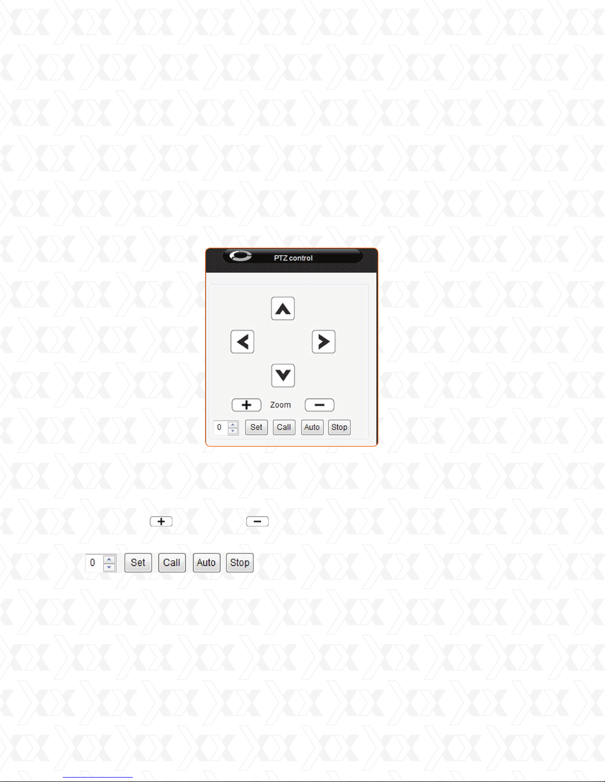
•
Select a display window, click Device settings to open the window shown below.
•
Click Get to show the actual parameters of the image.
•
Adjust the parameters by using the sliding bar or by entering a value in the box.
•
When done, click Save to store your settings.
•
You may set the original values by clicking Restore default.
18
Page 19
Nexxt Solutions - IP Camera Centralization Management Software
Note: If the running speed is slow when monitoring the cameras or the software is not working
properly, open Windows Task Manager and check the percentage of CPU usage. If it takes
more than 80%, the CPU might not be powerful enough. In this case, decrease resolution,
or remove monitoring devices. Each product series have different parameters settings. It is not
recommended to change them frequently.
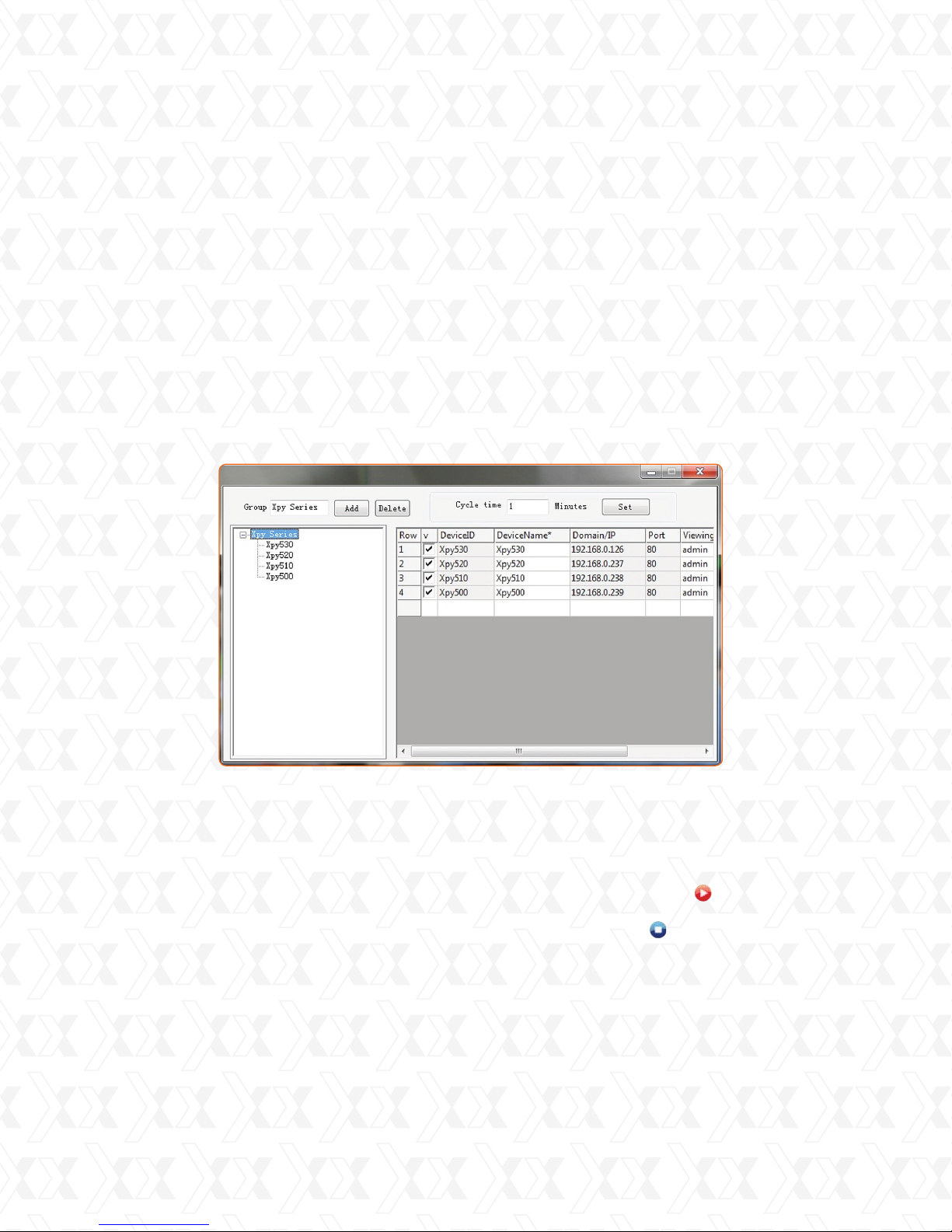
9. PTZ control
This feature is available based on the model of the camera. If your camera supports the Pan,
Tilt and Zoom feature, enable it by using the client software. Once enabled, the movement of the
camera can be controlled with the buttons in the PTZ control panel.
PTZ control
Click on the arrow icons ← → ↑ ↓ on the Pan, Tilt and Zoom on the control panel to turn
•
the camera up, down, left and right.
The arrows on the keyboard may also be used.
•
Click the Plus and the Minus icons, on the cameras supporting this feature to
•
control the zoom.
Use the buttons shown in the bar below, on the cameras featuring an external PTZ.
•
Enter a value to Set/Call the preset point.
•
Click Auto, to control the Pan, Tilt and Zoom cruise according to the preset point.
•
Click Stop to disable the Pan, Tilt and Zoom cruise.
•
19
Page 20
Nexxt Solutions - IP Camera Centralization Management Software
10. Managing a group
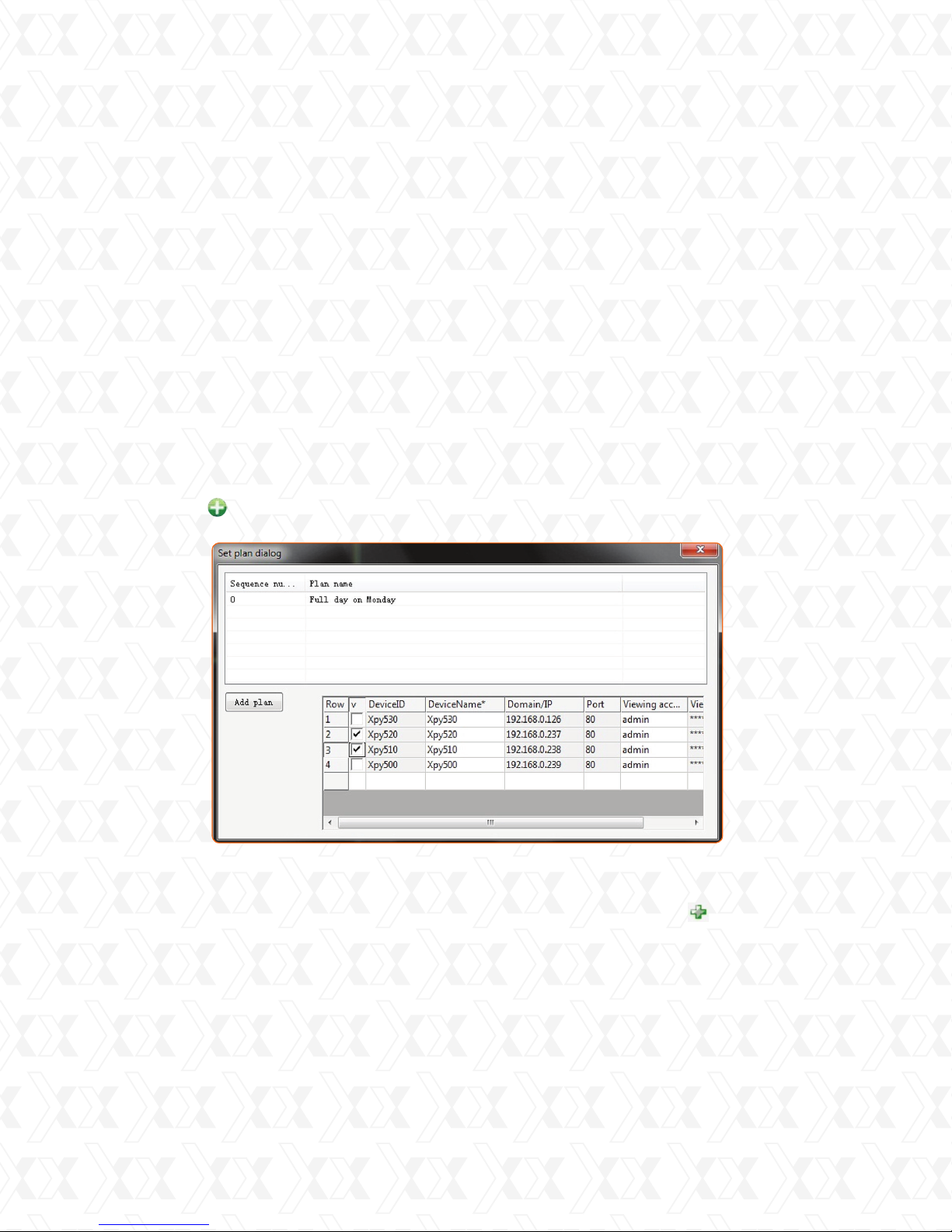
This feature allows you to set groups of cameras to be displayed in a cycle.
Click on Group management to add, edit and delete a group
10.1 Setting, editing and deleting a group
•
Click the Plus icon.
•
Enter the group name.
•
After selecting Add, the group name will be shown on the interface.
•
Highlight the group and check the cameras you wish to add to that group.
•
Enter the time, in minutes in the Cycle time eld.
•
Click Set when nished and the cameras added to that group will be displayed according
to that cycle interval.
•
Repeat the previous steps to add more groups or to edit.
•
Click Delete to remove an existing group.
10.2 Playing by group
•
Playing a single group: select the group from the list, double click on that group and all the
applicable cameras will start at the same time.
•
Playing all the groups by cycle: if no group is selected, when you click Play , each camera
will be played by cycle.
•
Stopping all the groups: if no group is selected, when you click Stop , all the cameras will
stop playing at once.
Setting a group
20
Page 21
Nexxt Solutions - IP Camera Centralization Management Software
11. Recording options
The IPC monitor supports three recording options:
•
Alarm recording: it starts when the alarm is triggered within the schedule. Files generated by
this type of recording are identied with an A.
•
Schedule recording: generates files identified with an S. (See specific section).
•
Manual recording: generates files identified with an M. When manual recording is available,
the recording icon is green and it turns red when the device is recording. After one hour, the
recording will be stopped if not stopped manually.
Note: All three types of recording generate .asf files which include the start time stamp and
end with the .avi extension.
11.1. Scheduled recording
This feature, allows you to set the time the devices will be recording.
•
Click Schedule record on the Main interface.
•
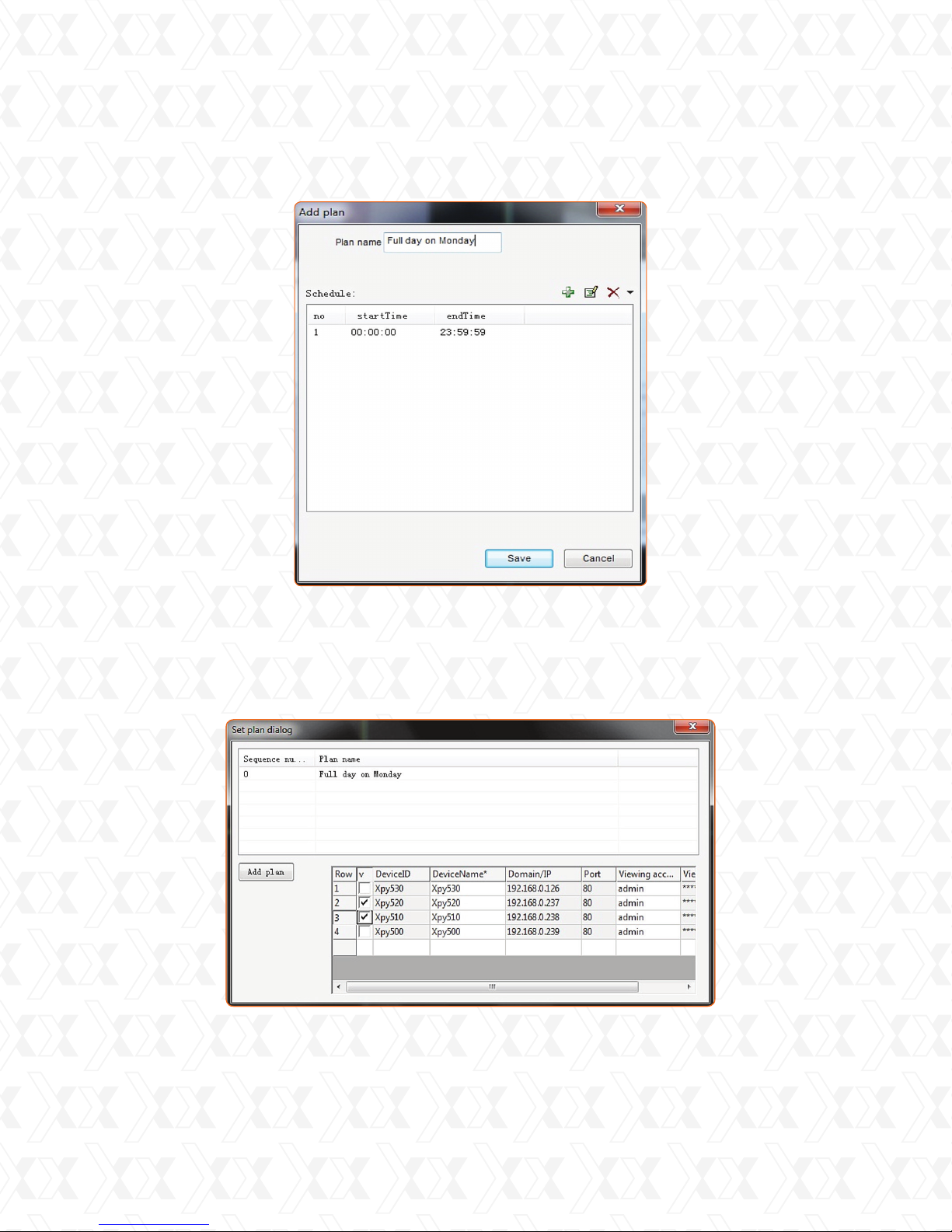
Click Add to open the Set plan dialog window.
•
Click Add plan to open the corresponding interface.
•
Enter a plan name, for example, “Full day on Monday”, after that, click Add
•
A new scheduled line will appear.
•
Set the starting and the ending time of the recording.
•
When nished, click Save to store your settings.
Note: A new recording le is created automatically every hour when the Scheduled recording
option is selected.
Set Plan Dialog interface
21
Page 22
Nexxt Solutions - IP Camera Centralization Management Software
Adding a plan
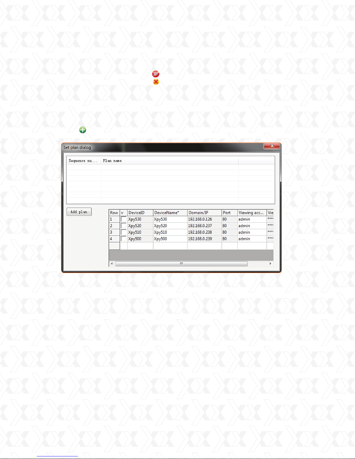
11.2 Adding cameras to the recording plan
• Select the plan name on the Set plan dialogue interface.
• Click the cameras you wish to add so that they record according to the plan.
Setting plan dialog interface
22
Page 23
Nexxt Solutions - IP Camera Centralization Management Software
11.3 Editing or deleting recording plan parameters
• Select a plan name and click Modify to change the recording values.
• Select a plan name and click Delete to remove a recording plan.
12. Setting the alarm
Apply alarms and alarm actions to a group of cameras.
• Click Alarm settings on the Main interface.
• Click Add to open the Set plan dialog interface.
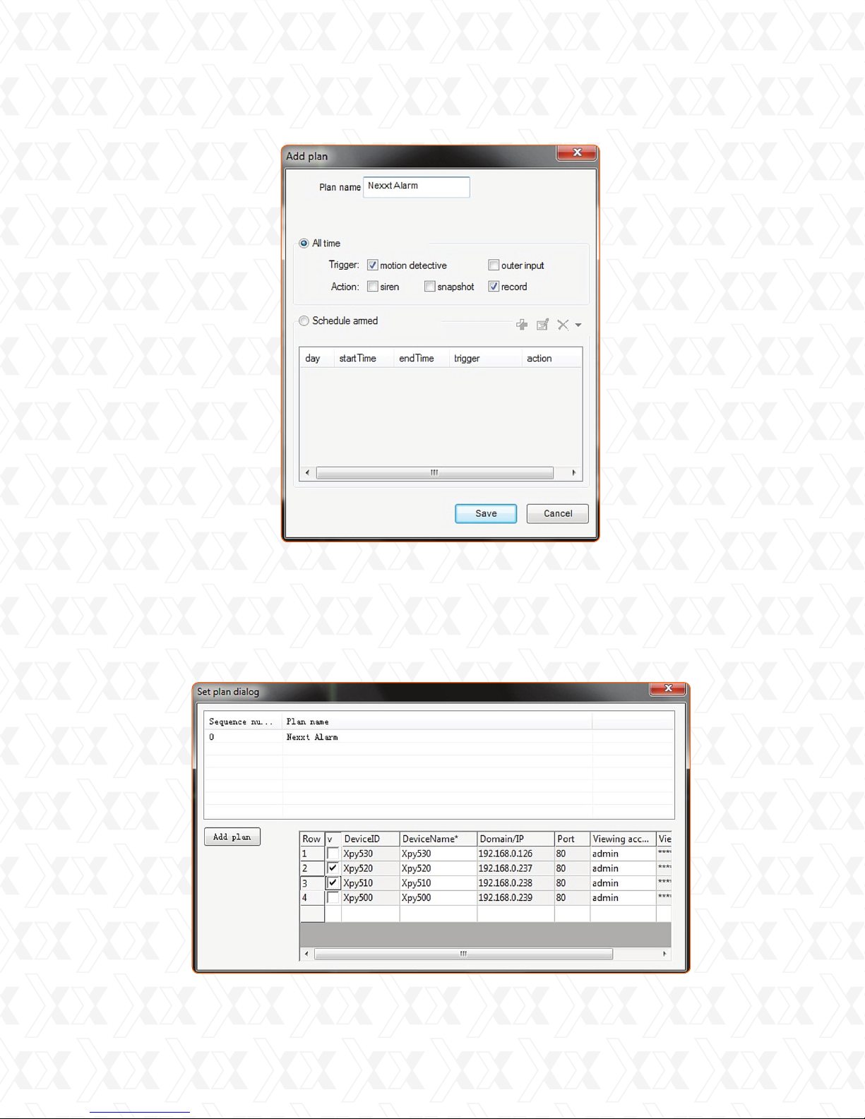
Alarm Plan Setting
• Click Add plan to open the Add plan interface.
• Enter a plan name, for example, “Nexxt Alarm”.
• Select All time to set the alarm 24/7.
- Select the trigger event, which can be Motion detection or Outer input.
- Select the type of action that will be activated by the trigger, for example, a siren, a snapshot
or recording.
- Click Save to store your settings.
• Select Schedule armed to set the alarm by hours per day.
- Add a day of the week, the starting and ending time.
- Select the type of trigger, which can be Motion detection or Outer input.
- Select the type of action that will be activated by the trigger, for example, a siren, a snapshot
or recording.
- Click Save to store your settings.
23
Page 24
Nexxt Solutions - IP Camera Centralization Management Software
Add plan
12.1. Adding the cameras to the alarm plan
• Select the plan name on the Set plan dialogue interface.
• Click the cameras you wish to add so that the alarm is set according to the plan.
24
Page 25
Nexxt Solutions - IP Camera Centralization Management Software
12.2 Editing or deleting alarm plan configurations
• Select a plan name and click Modify to change the alarm plan values.
• Select a plan name and click Delete to remove an alarm plan.
Note: before setting the alarm, make sure the IP camera conguration has been entered
correctly and that the alarm has been detected. (Refer to the IP camera user manual).
13. System settings
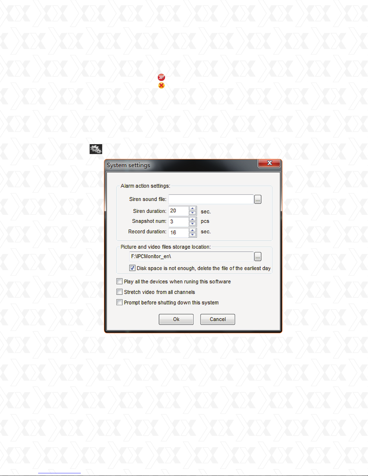
This interface allows you to congure settings of the alarm system, such as alarm action
settings and file storage location.
Click Settings to open the System settings interface.
13.1. Alarm action settings
•
Choose different .wav les to select other types of sounds, such as a siren sound.
The default sound is selected automatically, if this eld is left blank.
•
Other parameters can also be congured such as length of the siren, number of snapshots
and length of recording.
System settings
25
Page 26
Nexxt Solutions - IP Camera Centralization Management Software
13.2 Storage location:
Enter the location to store the video and snapshots taken during the alarm.
If default settings are not changed, snapshots and videos will be stored in: . /snap, and. /
record directory.
•
If this option is selected Disk space is not enough, delete the file of the earliest day,
the data stored the earliest day will automatically be removed. The system will start
deleting the les, when the disk space is less than 1GB. If not selected, the recording
will stop when the disk space is less than 500MB.
•
In order to set the storage location, click on the Browse icon to find the target file
location.
Other options may be selected such as:
•
Play all the devices when running this software.
•
Stretch video from all channels.
•
Prompt before shutting down this system.
Click OK to store your settings, otherwise, click Cancel.
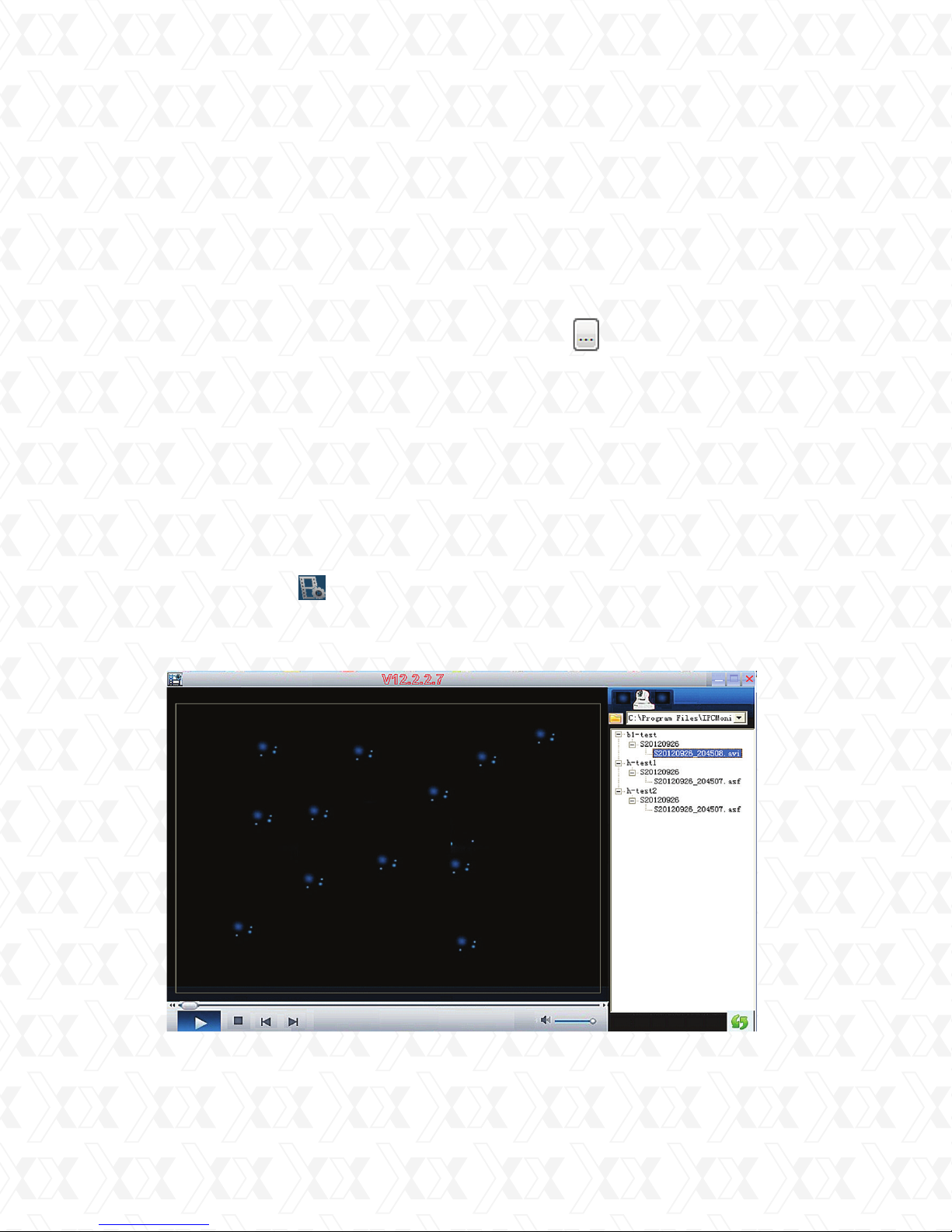
13.3 Playing recorded files
Use this feature to open the Playback panel and view previous recorded les.
•
Press the Playback button to open the panel.
•
Use the address field to enter the main location where the video file is stored.
•
Select the le to be played by entering it manually or by choosing it from the group tree
displayed on the right of the playback panel.
Playback panel
26
Page 27
Nexxt Solutions - IP Camera Centralization Management Software
14. Managing NVR (Network Video Recorder)
Click the NVR icon to launch the NVR recorder.
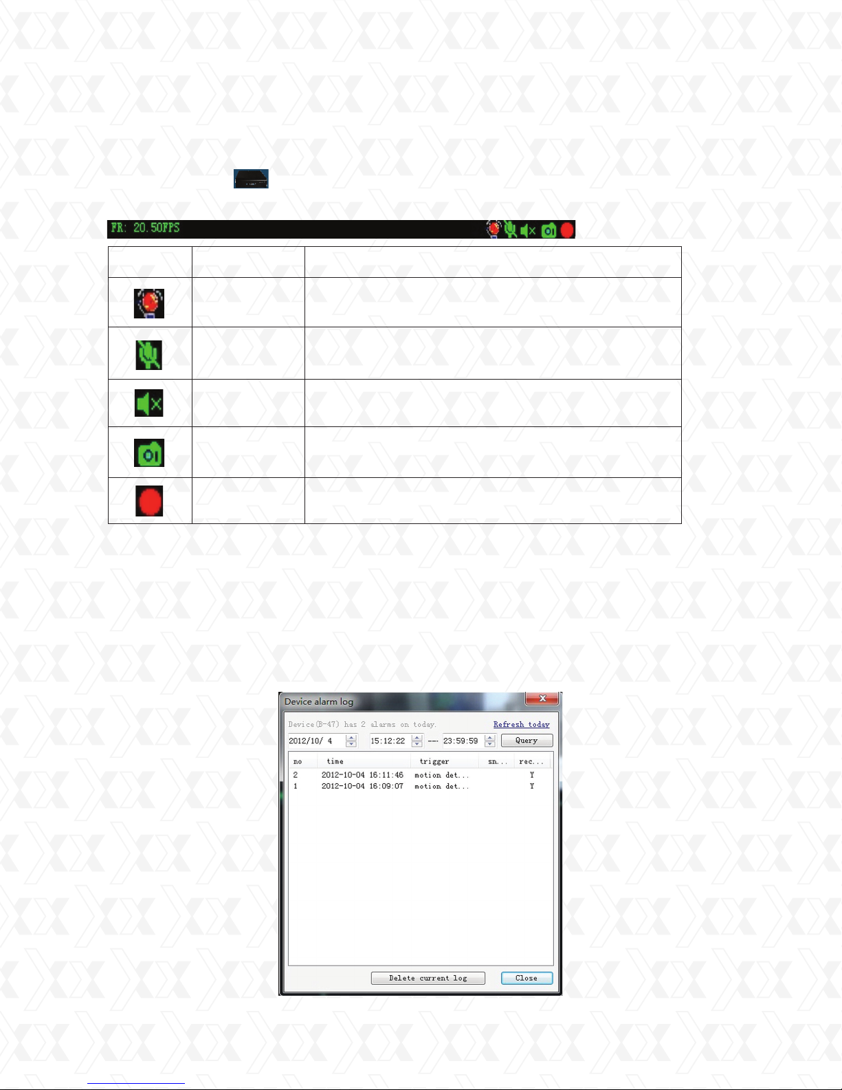
14.1. Icons on the channel status bar
Icon Name Description
Alarm
Microphone
Speaker Enables/disables sound.
Camera
Recording
This icon is displayed when an alarm is
detected by the device.
Enables speaking and it becomes disabled
when another user is talking.
Click it to take a snapshot
Click it for manual recording
14.2. Device alarm log interface
The Device alarm log captures and stores details about the system software activities.
It shows the date and time, the trigger event and the action taken.
•
Double click on the Alarm icon to display the alarm log interface, as shown below.
•
Select a date and a starting and ending time and click Query.
•
The events will be displayed on the screen starting with the most recent.
•
To delete a log entry, just highlight it and click Delete current log followed by Close to exit.
Alarm device log
27
Page 28

Nexxt Solutions - IP Camera Centralization Management Software
FCC Statement
This equipment has been tested and found to comply with the limits for a Class B digital device, pursuant to part 15 of the FCC Rules. These limits are designed to provide
reasonable protection against harmful interference in a residential installation. This
equipment generates, uses and can radiate radio frequency energy and, if not installed
and used in accordance with the instructions, may cause harmful interference to radio
communications. However, there is no guarantee that interference will not occur in a
particular installation. If this equipment does cause harmful interference to radio or
television reception, which can be determined by turning the equipment off and on, the
user is encouraged to try to correct the interference by one or more of the following
measures:
This device complies with part 15 of the FCC Rules. Operation is subject to the
following two conditions:
Reorient or relocate the receiving antenna.
•
Increase the separation between the equipment and receiver.
•
Connect the equipment into an outlet on a circuit different from that to which the
•
receiver is connected.
Consult the dealer or an experienced radio/ TV technician for help.
•
28
 Loading...