

Page 1
www.nexxtsolutions.com
XpySeries
XPY-8004-HD / XPY-4004-HD / XPY-4002-HD
HIGH DEFINITION MULTI-CHANNEL SURVEILLANCE SYSTEMS
Page 2
Nexxt Solutions - Surveillance systems user guide
1
2
3
Nexxt Solutions - Surveillance systems user guide
I. Introduction
Thanks for purchasing the Nexxt Solutions standalone video surveillance system with the
latest in HD-TVI technology. This multi-channel security DVR is an easy to install, easy to
setup and easy to use monitoring kit. Upon opening the box, make sure all the items listed
below are included in the package:
A. DVR kit
Eight (8) or four (4) channel H.264 DVR
•
AC adaptor for DVR and cameras
•
USB wired mouse
•
CD ROM with free mobile app and digital user guide
•
M3.5x5 hard drive screws
•
User guide
•
1 pc
1 pc
1 pc
1 pc
4 pcs
1 pc
B. Xpy8004-HD and Xpy4004-HD camera kits
HD TVI indoor/outdoor CCTV security camera
•
BNC male to BNC male cable with power connector
•
One-to-five power splitter
•
One hardware kit per camera
•
- PA4x25- screw
- Anchor
- Drill template
- Wrench
4 pcs
4 pcs (20 meters each)
1 pc
4 sets
3 pcs
3 pcs
1 pc
1 pc
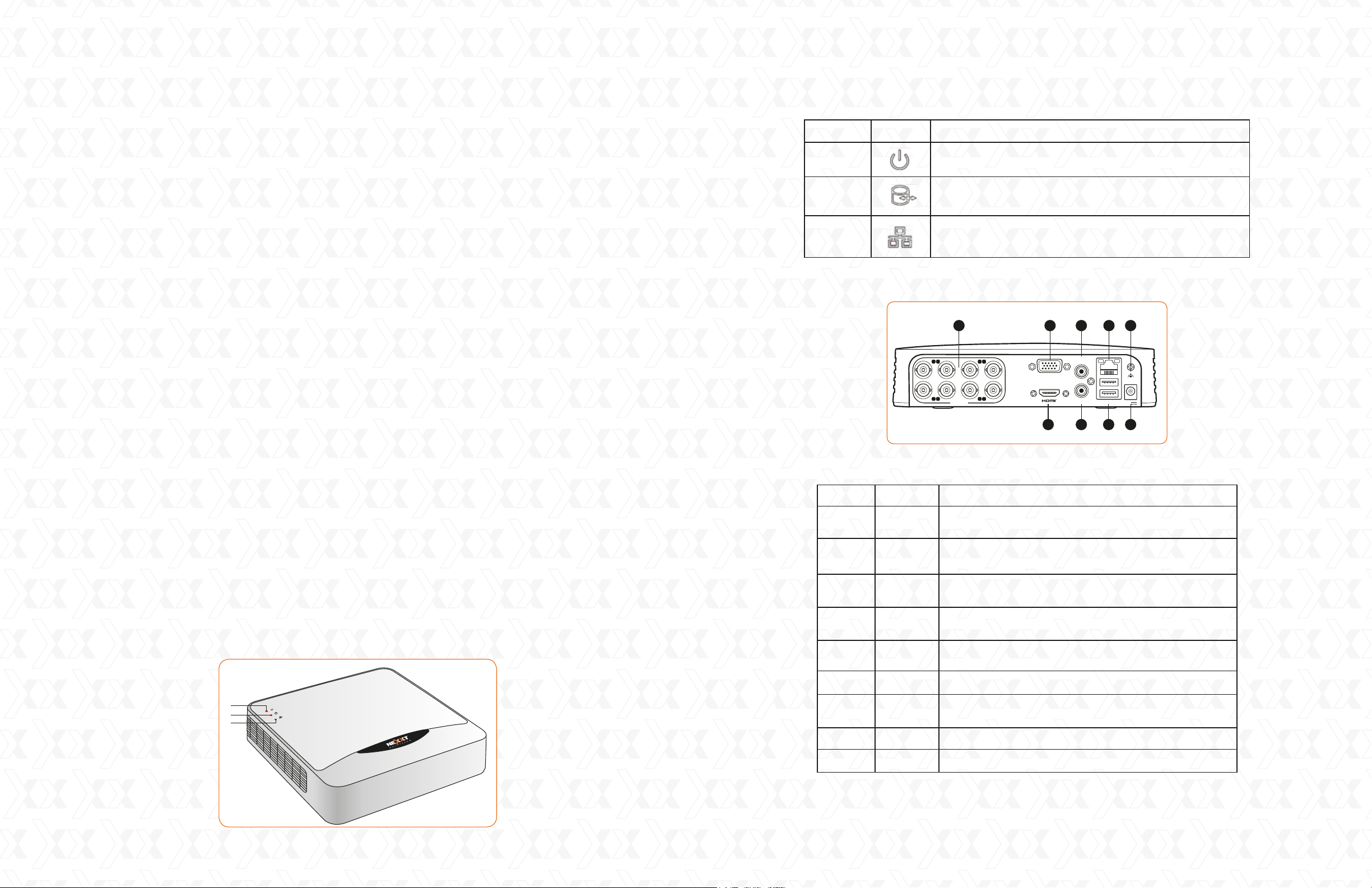
Number Icon Description
Back view
1
2
3
The power LED lights solid red when the DVR
is plugged in
The HDD indicator LED lights red when data is being
read from or written to the hard disk drive successfully
The network icon blinks blue when the connection
is functioning properly
1 3 4 86
1 2 3 4
5 6 7 8
VIDEO IN
AUD IO IN
VGA
AUD IO O UT
LAN & USB
12V
2 5 7 9
C. Xpy4002-HD camera kit
(Diagram based on the 8-channel version)
HD TVI indoor/outdoor CCTV security camera
•
BNC male to BNC male cable with power connector
•
One-to-five power splitter
•
One hardware kit per camera
•
- PA4x25- screw
- Anchor
- Drill template
- Wrench
II. Front and rear panel description
Front view
2 pcs
2 pcs (20 meters each)
1 pc
2 sets
3 pcs
3 pcs
1 pc
1 pc
Number Item
1
2
3
4
5
6 RJ-45 10Mbps/100Mbps Ethernet interface
7
8
9
VIDEO IN
HDMI
VGA
AUDIO IN
AUDIO OUT
LAN PORT
USB PORTS
GND
12V
BNC jacks for analog and high denition video input
from 4 or 8 channels, depending on the version
High-denition jack to connect a compatible screen
or monitor for video output
DB15 jack to connect a compatible screen or monitor
for video output
RCA jack for cameras equipped with audio or a
microphone
Connect a speaker to this RCA jack for amplied
audio output
High-speed interface to connect a mouse and
external USB backup devices
Ground (needs to be connected when DVR starts up)
DC input to connect the supplied 12V power adaptor
Description
2
3
Page 3
Nexxt Solutions - Surveillance systems user guide
Nexxt Solutions - Surveillance systems user guide
III. Hard drive installation
Note: all DVR systems can run and monitor normally without a hard disk, but video recording
and playback will not be possible.
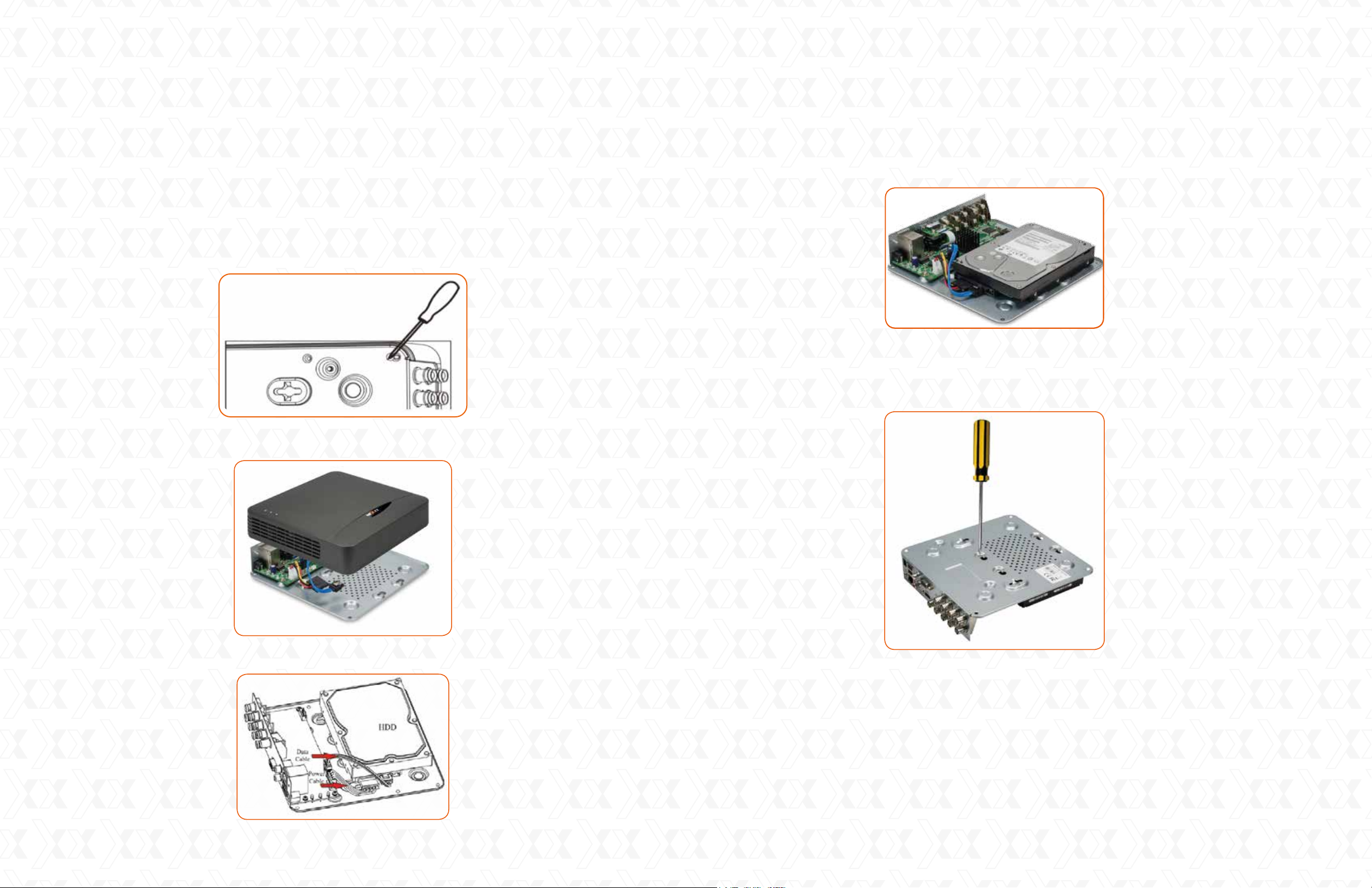
The system does not include a SATA hard disk drive (HDD). A HDD unit must be purchased
separately and installed by the user. To do so, you must follow the procedure described below:
Before proceeding with the HDD installation, make sure that the DVR is powered off and that
1.
all cables are disconnected from the power source.
Use a screwdriver to unfasten the four screws located on the bottom panel of the chassis.
2.
Lift the top cover away from the unit to remove it.3.
Next, insert the SATA interface plug into the corresponding connector on the hard drive.
5.
Then, attach the SATA power plug with the terminal on the HDD unit.
Use the supplied four mounting screws to secure the drive to the DVR chassis. To do that, align
6.
the drive with the holes on the base of the DVR, and screw them from the bottom.
Locate the HDD rack in the DVR motherboard. 4.
Be careful not to exert too much pressure when tightening the screws in order to secure the
7.
drive to the DVR.
Replace the cover by sliding it back on, making sure that the edges are perfectly aligned with the
8.
screws on the bottom.
Gently push the top cover down and fasten it using the same four screws you removed earlier.
9.
4
5
Page 4
Nexxt Solutions - Surveillance systems user guide
Nexxt Solutions - Surveillance systems user guide
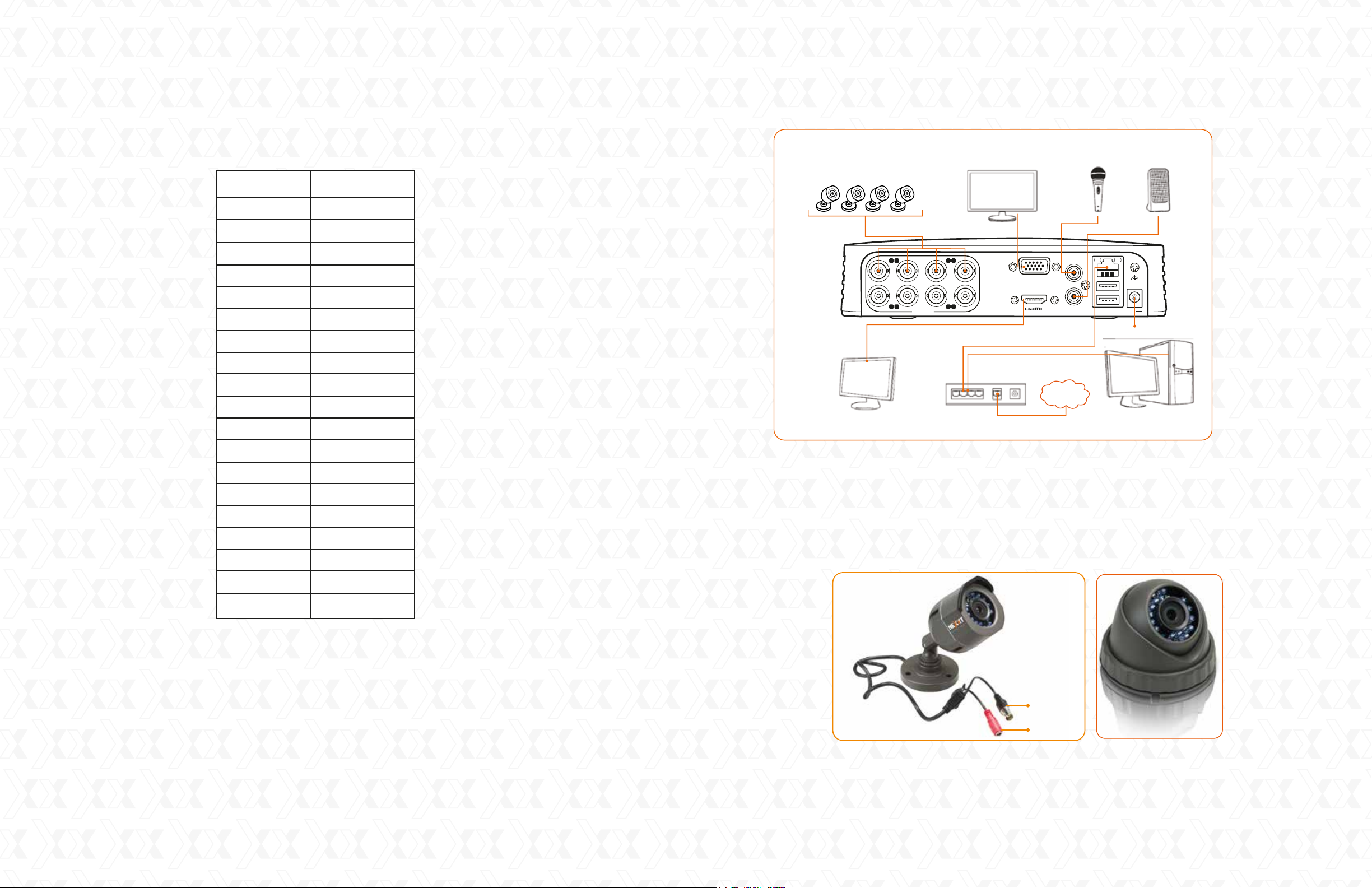
IV. HDD storage calculation chart
The following chart shows an estimation of storage space used, based on recording at one channel for
an hour at a fixed bit rate. Please note that this should be used for reference only.
Bit rate Storage used
96kbps
128kbps
160kbps
192kbps
224kbps
256kbps
320kbps
384kbps
448kbps
512kbps
640kbps
42M
56M
70M
84M
98M
112M
140M
168M
196M
225M
281M
DVR connections –power, video, audio and network
Cameras
TV Monitor
(Not included)
1 2 3 4
5 6 7 8
VIDE O I N
VGA Monitor
(Not included)
Router and/or switch
(Not included)
VG A
Microphone Speaker(s)
AUD IO IN
AUD IO O UT
INTERNET
LAN & US B
12V
DC in
PC
(Not included)
768kbps
896kbps
1024kbps
1280kbps
1536kbps
1792kbps
2048kbps
3072kbps
337M
393M
450M
562M
675M
787M
900M
1350M
V. Hardware installation
Choose the optimum location for the DVR. The best place is within a 20m radius from all
1.
the cameras and within reach of an available wired internet connection.
Proceed with the internet connection and the installation of the user supplied monitor(s)
2.
with a VGA or HDMI connection.
If adding speakers, connect them to the audio output (RCA jack) located on the rear panel
3.
of the unit.
Using the supplied screws and anchors, mount the cameras. For distances over 20m, you
4.
must purchase extension cables to cover that extra run. For detailed mounting instructions,
please refer to our online manual at www.nexxtsolutions.com.
Once you have correctly positioned the cameras in the preferred monitoring location, firmly
5.
attach the BNC and power connections of each camera to the terminals of each individual
extension cord.
(Diagram based on the 8-channel version)
On the DVR side, attach the BNC cables to the video ports of each camera located on the
6.
rear panel of the unit, as marked.
Note: This system supports analog and TVI technologies. Both streaming formats can be
used simultaneously as long as channels are used in pairs. For instance, channel 1 and 2
must be fitted with TVI cameras, while 3 and 4 with analog, and so forth.
Video
Power
Connect one end of the Ethernet cable to the RJ45 port located on the rear panel of the unit,
7.
and the other end to an available LAN port on your network or router.
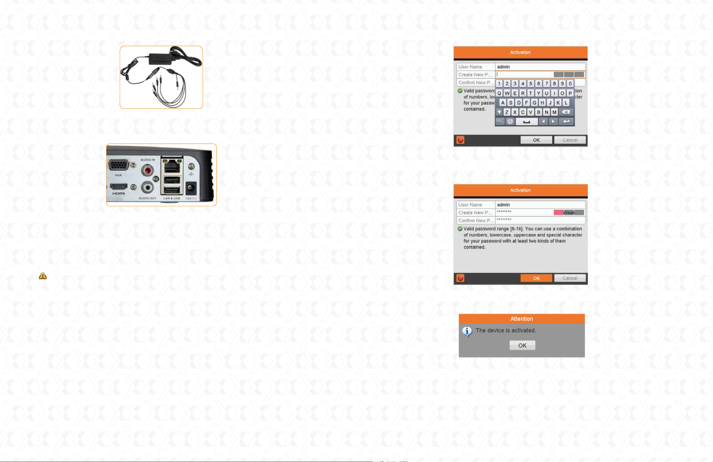
Attach the splitter to the supplied AC. Then, connect the power terminals of all cameras and
8.
the DVR to the power splitter.
6
7
Page 5
Nexxt Solutions - Surveillance systems user guide
AC adaptor and splitter
Now, you can connect the mouse on any of the two USB ports on the rear panel. The mouse is
9.
the default tool for navigating through the menus.
Nexxt Solutions - Surveillance systems user guide
1.2
The password field has a strength indicator that analyzes the level of security in real time of
the sequence you have chosen. Once you are satisfied with the newly created authentication
code, click OK to continue.
Finally, plug the AC adaptor to any standard wall outlet to power on the DVR.
10.
Note: We highly recommend the use of an Uninterruptible Power Supply (UPS) in conjunction
with the device.
VI. Preliminary steps
When switching on the DVR for the first time, the system will boot up. During this initial process,
you will be prompted to enter some basic parameters and network settings. You can either use
default values or enter your own settings, based on your system requirements or special needs.
IMPORTANT! If you are logging into the DVR for the first time, it is essential that you set the
device to the correct time and date at this point, to facilitate the search for events based on when
they occurred, as well as avoiding confusion by having several recorded files bearing the same date.
VII. Using the setup wizard
The Setup Wizard walks you through some important settings of the device. By default, the Setup
Wizard starts once the device has loaded.
1. Activation window:
This option will require you to create your own password for privacy considerations.
As with all devices of this type, it is important to set a customized password in order to stop anyone
accessing your device or changing settings.
Make sure to setup a password hard for anyone to guess, but one you can remember. As this is a
“one time log in” opportunity, please note that you will not be able to sign into your account again if you
accidently lock yourself out of the system. In that case, you may need to contact our technical support
department for assistance.
If successful, the DVR will display the following dialog window. Click OK to move on to
1.3
the language setup menu.
As soon as the system is turned on, you are required to set up your credentials as an administrator.
1.1
Enter the desired alphanumeric sequence and confirm your selection. As displayed in the dialog box
below, your password must meet the system minimum requirements in order to be accepted.
8
9
Page 6
Nexxt Solutions - Surveillance systems user guide
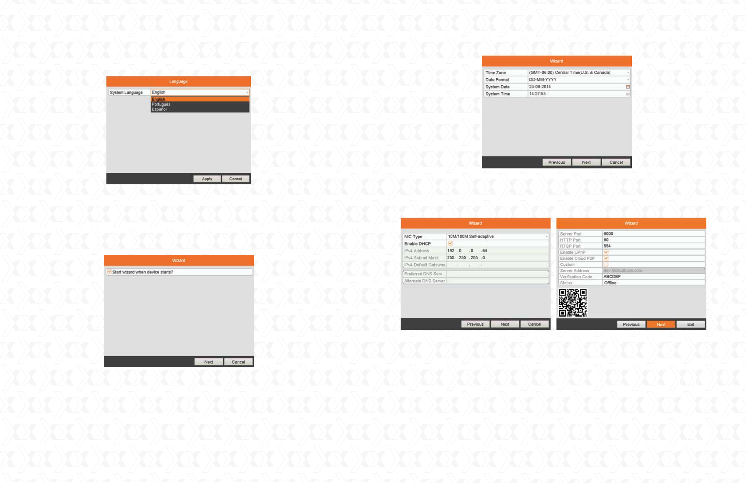
2. Language: There are three languages available in the system: English, Portuguese and Spanish.
English is the language by default. Click Apply to continue.
Please note that if you select other language different from the default, the system will prompt you
to reboot in order to apply the correct language package.
Nexxt Solutions - Surveillance systems user guide
5.
Network configuration: Defines network parameters, including the NIC type, IPv4 address,
IPv4 subnet mask, default gateway, server port, etc. By default, this is set to DHCP, to
automatically obtain an IP address and other network settings from that server. Follow the
onscreen dialog boxes and click Next in both instances to enter the HDD Management window.
3.
Start wizard interface: This box is checked by default, and it is designed to enable the setup
wizard when the device starts. If you would like to disable this option, uncheck this box.
It is recommended to leave the default configuration unchanged the first time to set the
proper settings. Click Next to continue with the setup.
Date and time: Use this window to set the time zone based on your current location, date
4.
format, system date and time. Once done, click Next to configure the network settings.
6.
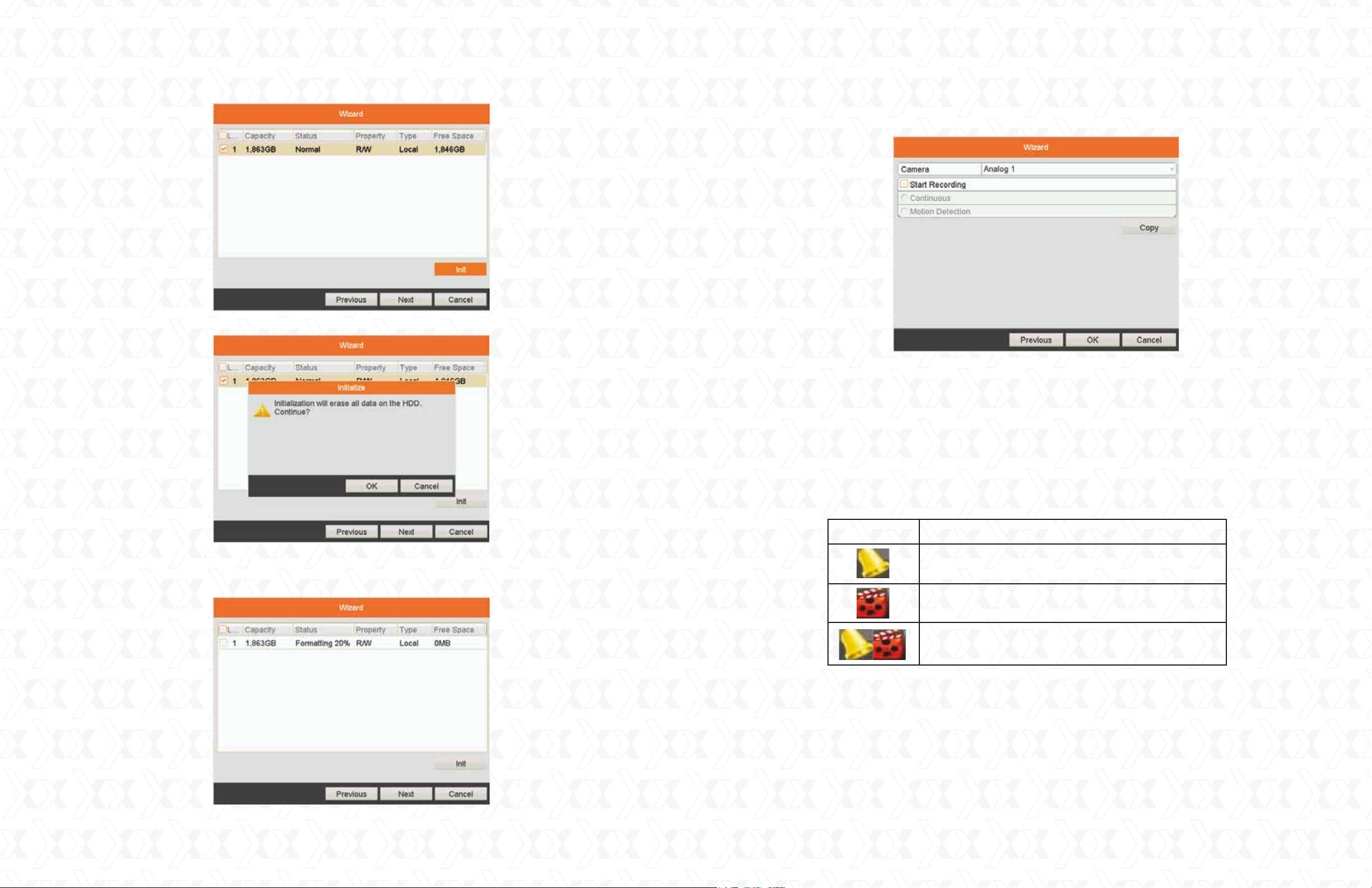
HDD management: When using a hard drive for the first time, the system will prompt you to
initialize the disk. Please note that initialization will remove all the data stored in the hard drive.
6.1
To proceed, select the hard drive from the list, click Init, followed by OK, as shown below.
10
11
Page 7
Nexxt Solutions - Surveillance systems user guide
Nexxt Solutions - Surveillance systems user guide
7.
Camera settings: This window allows you to select the camera to be configured, enables
the recorder function and the mode you wish to assign to each channel.
7.1
Click Copy to replicate the record settings of the current camera to any other camera(s).
Click OK to return to the Record setting window.
7.2
During this process, the formatting status will be displayed on the screen.
6.2
When it is 100% complete, click Next to move on to the following window.
8.
Once all parameters have been configured, select OK to complete the Setup Wizard.
VIII. Live view
The normal mode of the DVR is to display live footage from the cameras. The device automatically
enters the Live View mode when powered on.
In addition to the images captured by the cameras, the DVR displays icons that represent the
status of each device connected to the network.
Icon Description
An alarm event has been triggered (video loss,
tampering or motion detection )
Recording mode (manual, scheduled,
or motion detection)
Alarm and recording functions are both enabled
In this mode, the menu bar will be displayed in the lower edge of the screen. To bring it up, you can
scroll down the cursor or simply click on the mouse right button.
12
13
Page 8
Nexxt Solutions - Surveillance systems user guide
Nexxt Solutions - Surveillance systems user guide
3 4 5 8 9 10 12116 721
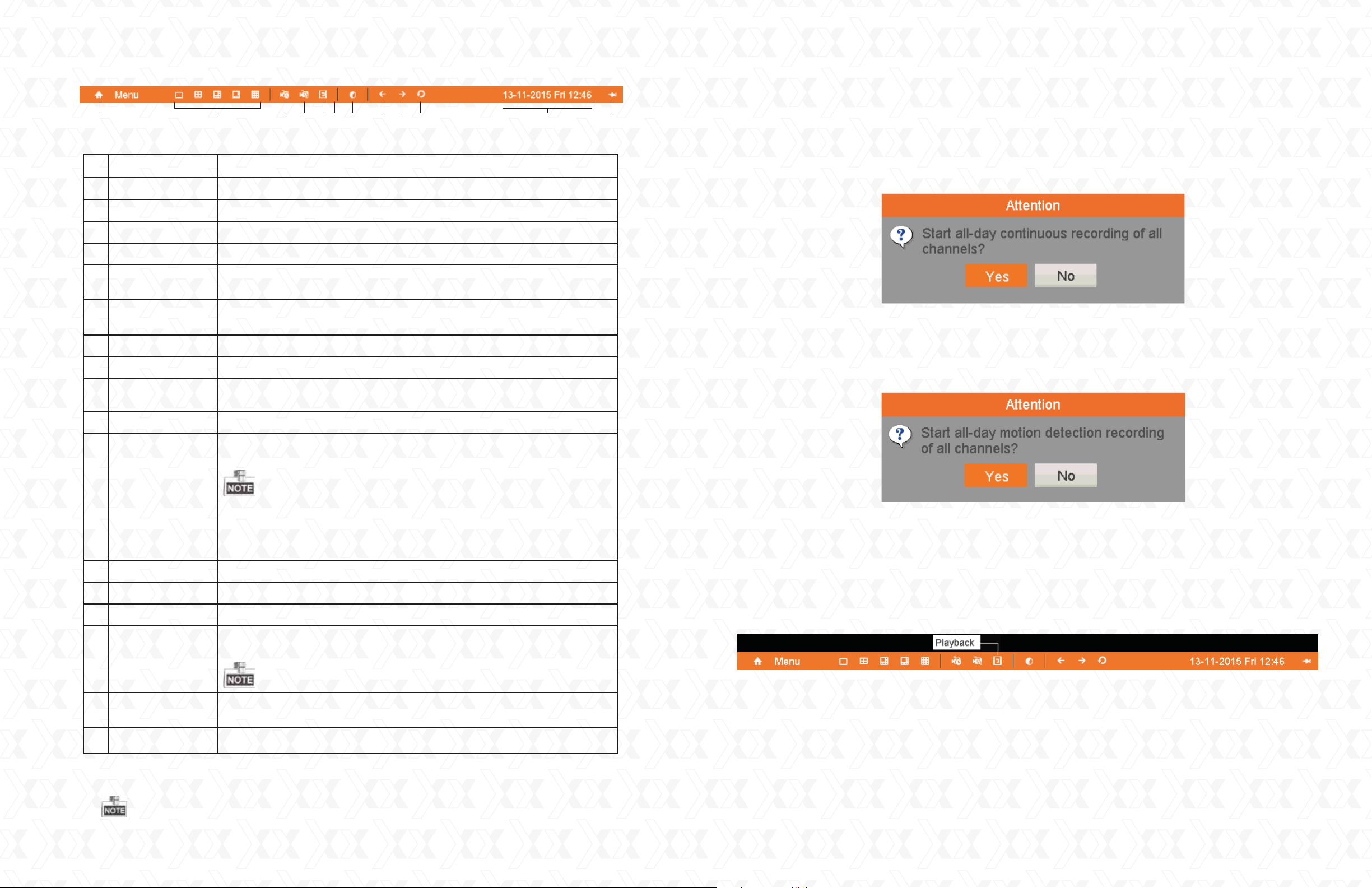
Menu bar display
Name Description
1 Brings up the main menu interface of the system
Home menu
Viewer options
1x1
2x2
1x5
Switches among the available screen display modes included below2
Single view
Quad view
Five-channel grid view plus one enlarged frame
(8-channel version only)
1x7
Seven-channel grid view plus one enlarged frame
(8-channel version only)
Nine-channel grid view (8-channel version only)3x3
Enables the continuous recording option for the active channels3 Normal record
4 Motion detection
Enables recording when motion is detected in any of
the selected channels
5 All-day playback
Plays back the video of the selected channel
1. Record
From the live view interface, the user can configure the recording settings for all channels.
1.1
Click the Normal record icon on the menu bar to launch manual recording.
1.2
When the following window pops up, click Yes to finish the quick recording settings for the
selected cameras.
2. Motion detection record
From the live view interface, the user can enable the motion detection feature on all channels.
2.1 Click the Start all day motion detection icon on the menu bar to launch the application.
6 Aux monitor
10 Start/stop
auto-switch
11 Date and time
Switches to the auxiliary output mode (BNC), in which case the
main output is disabled.
If the Aux monitor mode is selected, make sure to have the
BNC device connected to the video output in order to enable
full mouse function.
If you enter the Aux Monitor mode (no output plugged in), you can
recover the full function by clicking 3-4 times on the scroll wheel
of the mouse.
Sets the video output mode to standard, bright, gentle or vivid7 Output mode
Displays the preceding page or item8 Previous screen
Displays the following page or item9 Next screen
Enables/disables the auto-switch feature to display footage from
the active channels.
The dwell time in live view mode must be set before
activating this feature in the DVR
Displays the system date and time information in the
selected format
Use it to pin the tool bar on the screen for quick access to menus12 Pin
2.2
When the following window pops up, click Yes to finish the quick motion detection settings
for the selected cameras.
3. Playback
Playback options can be directly configured from the live view interface.
3.1
Click the All-day playback icon on the menu bar to launch the application.
The interface includes a toolbar on the bottom of the screen containing all the controls
3.2
to manage the playback process.
IX. Main DVR functions
After a certain period of inactivity, the system will prompt you to reenter your username
and password.
14
15
Page 9
Nexxt Solutions - Surveillance systems user guide
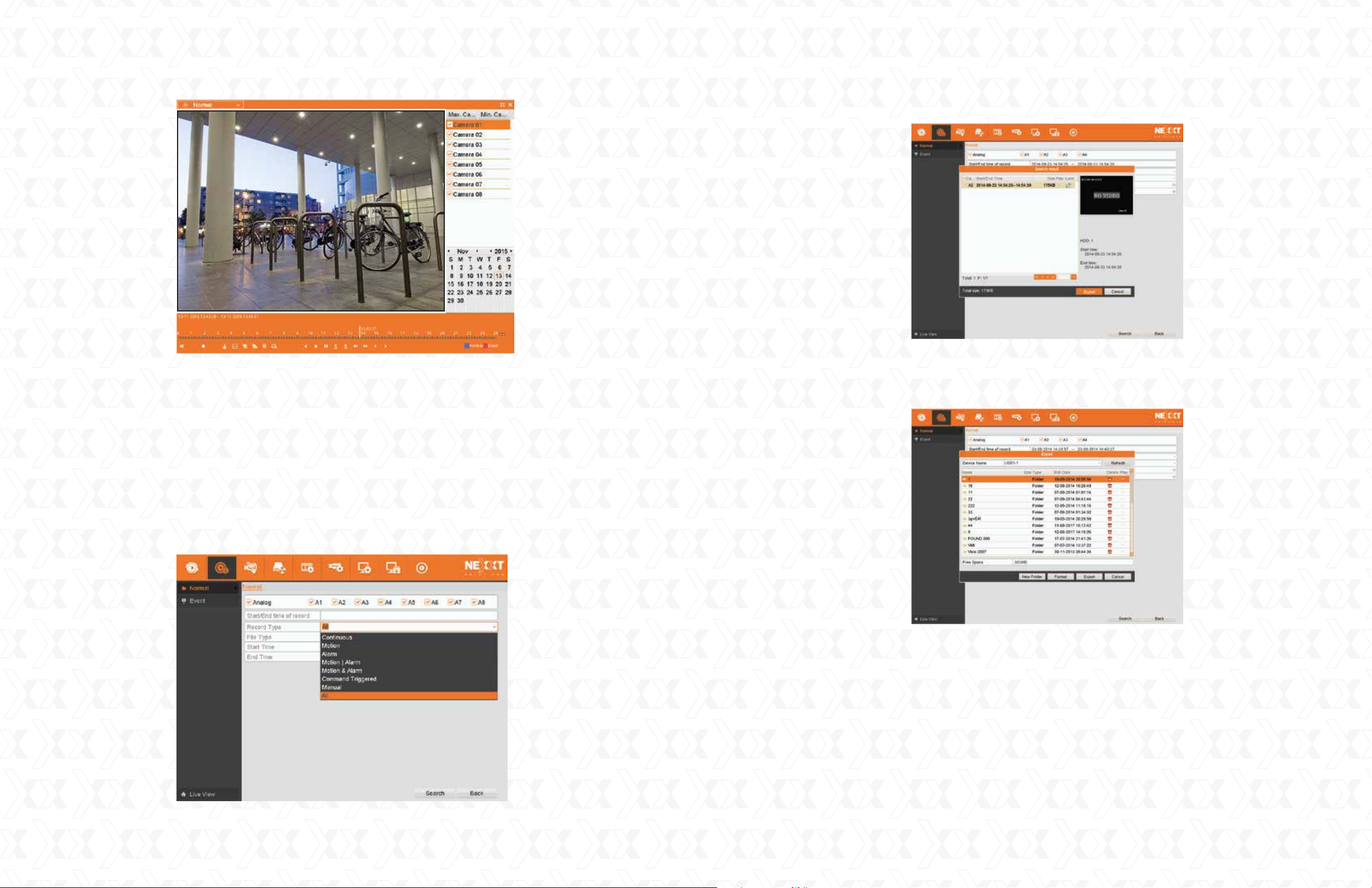
In addition, by moving the cursor to the right side of the screen, the complete list of channels
3.3
will be displayed. From this window, the user can select the videos recorded by each particular
camera he wants to view.
Nexxt Solutions - Surveillance systems user guide
4.2
Select the recorded files and click Export.
4.3
Browse to choose the backup device and click the Export button to start the file(s) transfer, as
illustrated below. The user can delete or check the saved files by clicking on the corresponding
icon on the right hand column.
4. Backup
Recorded files can be backed up in external memory devices, such as USB flash drives, USB
hard disk drives or a DVD writer.
To export recorded files:
4.1
Click Home menu > Export > Normal to enter the video export interface.
Choose the channel(s) and file types you want to back up from the Record Type line.
Then click the Search button to continue.
5. Startup and shutdown
Proper startup and shutdown procedures are crucial for expanding the life of the DVR.
5.1
Make sure that voltage of the AC mains or of the UPS system you are using matches the power
requirements of this unit.
5.2
Verify that all power and ground connections have been done properly.
5.3
When connected, the power indicator LED will glow red.
5.4
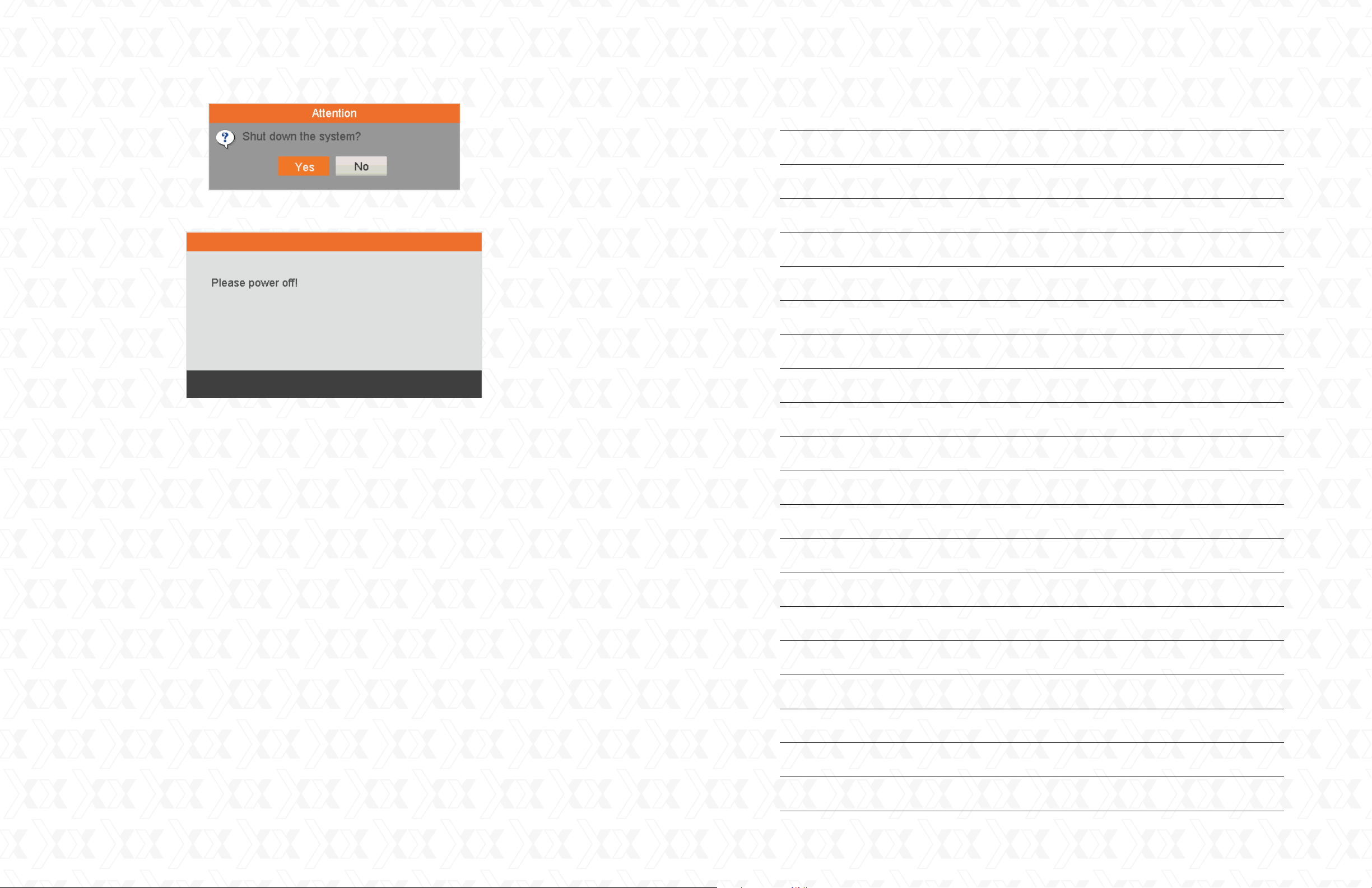
To disconnect the system, use the mouse to select Home menu, followed by the Shutdown
option in the menu.
5.5
Then the Shutdown confirmation window will be displayed. If you want to continue, click Yes,
as seen in the illustration below.
16
17
Page 10
Nexxt Solutions - Surveillance systems user guide
At this final stage, you can safely unplug the DVR from the power source.5.6
Notes
18
19
 Loading...