

Page 1
WebWise
16/24 Port Gigabit Ethernet Switch
User`s Manual
Page 2

Nexxt Solutions
Copyright Statement
Nexxt Solutions is a registered trademark. Other trademarks or brand names contained herein are the trademarks or registered brand names of their respective
owners. Copyright of the whole product as integration,
including its accessories and software, belongs to Nexxt
Solutions Ltd. No individual or third party is allowed to
copy, plagiarize, reproduce, or translate it into other
languages, without express consent from Nexxt Solutions.,
Ltd. All of the photos and product specifications mentioned
in this manual are used as reference only. Upgrades of
software and hardware may occur, and should there be
any changes, Nexxt Solutions shall not be responsible for
notifying about any such modifications in advance. If you
would like to know more about our products, please visit
our website at www.NexxtSolutions.com.
Page 3

CONTENTS
Chapter 1 Product Overview 4
1.1 Features 4
1.2 Package Contents 6
Chapter 2 Hardware
Installation 7
2.1 Front Panel 7
2.2 Rear Panel 10
2.3 Environmental Requirements 10
2.4 Hardware Installation 11
Chapter 3 Configuration 14
3.1 Fast Login 14
3.2 Status 16
3.3 Port Setting 16
3.3.1 Port 17
3.3.2 Rate Limit 18
3.3.3 Storm Control 20
3.3.4 Statistics 21
3.4 Mirror 22
3.5 VLAN 22
3.5.1 VLAN Mode 23
3.5.2 Port VLAN 24
3.5.3 802.1Q VLAN 25
3.5.4 Tag VLAN Configuration 26
3.6 Trunk 27
3.7 QoS 28
3.8 MAC Address Setting 30
3.8.1 MAC Filter 30
3.8.2 Static MAC 31
3.9 802.1X Setting 31
3.9.1 802.1X 32
3.9.2 802.1X Port 33
3.10 RSTP Setting 33
2
Page 4

CONTENTS
3.10.1 RSTP 34
3.10.2 RSTP Port 35
3.10.3 RSTP Status 36
3.11 IGMP Snooping 37
3.11.1 Snooping Configuration 38
3.11.2 Snooping Status 39
3.12 System 40
3.12.1 SNMP 40
3.12.2 Change Password 42
3.12.3 Cable Diagnostics 42
3.12.4 Upgrades 42
3.12.5 IP Configuration 44
3.12.6 MAC Aging 45
3.12.7 Restoring Factory Configuration 46
3.12.8 Backup 46
3.12.9 Restore 47
3.12.10 Logout 47
Appendix 1 Common Commands 48
Appendix 2 TCP/IP Address Setting (Windows XP
as Example) 49
Appendix 3 Online Technical Support 51
3
Page 5

Chapter 1-- Product Overview
Thank you for purchasing this high performance 16/24
port Web Wise Switch. The
NW223NXT56/NW223NXT57
is a rack-mountable Gigabit Ethernet Switch, specially
designed for small to medium businesses that require
high performance network connectivity along with
advanced web management capabilities. It features
UTP/STP RJ-45 ports with auto MDI/MDIX, which can
operate at 10/100/1000Mbps. In addition, it has two
SFP shared expansion slots supporting GBIC modules,
designed to convert a standard Gigabit connection to
optical interface, and vice versa. A network range can be
extended from 100 m on Ethernet cable to over 80 km
using the SFP optical module. Gigabit ports can also be
used as normal or uplink ports to connect a backbone
network. By integrating a
NW223NXT56/NW223NXT57
switch into your network, the speed and network
efficiency will be significantly enhanced. Web-based
management features include port mirroring, VLAN,
QoS, port security, trunking, and traffic monitoring. Its
standard 19-inch rack-mountable case and intelligent
management capabilities make it the ideal choice for
small and medium sized networks.
1.1 Features
Complies with the IEEE802.3,IEEE802.3u, IEEE802.3ab
and IEEE802.3x Ethernet standards.
Features 16/24 10/100/1000 Mbps autonegotiation
RJ-45 ports, and supports automatic identifying of
parallel/cross-connected lines (Auto MDI/ MDIX)
Provides 2 shareable SFP interfaces, and supports Giga
Ethernet port and SFP fiber port auto-negotiation.
4
•
•
•
Page 6

Supports IEEE802.3x flow control for full duplex, and
backpressure flow control for half duplex.
Store and forward architecture, integrated 8K MAC
address table, and meets all application demands.
Up to 32/48Gbps backplane bandwidth, and supports
non- blocking line speed forwarding.
Supports up to 16/24 groups of port-based VLAN, and
supports up to 128 groups of Tag VLAN based on IEEE
802.1Q, with VLAN ID ranging 1 ~ 4094
Supports IEEE 802.3ad port trunk function, with 8 trunk
groups, each of which can contain up to 8/12 port
members.
Supports up to 128 static MAC address tables.
Supports the QoS function, and provides the mapping
mode based on the port, IEEE802.1p and TOS priorities
and the automatic control for transfer queue based on 4
priorities.
Provides control over port access security, and supports
control over port MAC address filtering, binding and
aging.
Supports broadcast storm smart control function.
Supports port mirroring function.
Supports the 802.1X authentication function.
Compatible with the 802.1D Spanning Tree Protocol
(STP) and supports the 802.1W RSTP.
Supports the IGMP Snooping function.
Supports IP address naming mode, or auto searching by
running a DHCP client to get an IP address.
Supports Web management.
Supports SNMP management.
Supports the upgrade of switch software and backup,
including the restoration of switch configuration files.
Supports cable diagnostic function.
Supports traffic statistics function, and dynamically
displays the packet receiving-transfer rate present at the
5
•
•
•
•
•
•
•
•
•
•
•
•
•
•
•
•
•
•
•
Page 7

port.
Equipped with a universal power supply, and a 1U steel
chassis for standard installation in a 19-inch rack.
1.2 Package Contents
Upon opening the box, ensure that the following items
are included:
One
NW223NXT56/NW223NXT57 Gigabit Ethernet Switch
One power cord
One CD with a User’s Manual and Quick Installation Guide
Rack-mount bracket kit
Self adhesive pads (for on-shelf installation)
If any of the listed items is missing, mismatched, damaged or broken, contact your local dealer immediately for
replacement.
6
•
•
•
•
•
•
Page 8

Chapter 2 Hardware Installation
2.1 Front Panel
The NW223NXT56/NW223NXT57 switches include the
following main components: network ports, status
indicators and a reset button, as shown below.
Front Panel of the 24-port switch
Front Panel of the 16-port switch
Status indicators:
Every Giga port provides 1 Link/Act Port, 1 100Mbps
indicator, and 1 1000Mbps indicator. The SFP port and
Giga RJ45 port share the same group port indicator: 1
Link/Act, 1 1000Mbps. Besides these, the switch also
has 1 SYS LED indicator, and 1 power indicator. It is
possible to check the switch status by looking at the
orange LED indicators, as shown in the table below:
7
Page 9

The 1000Mbps and Link/Act indicator will light at the
same time when sharing the SFP fiber port.
Reset button: Located at the lower left corner of the
front panel, this button is used to clear the current
8
LED Indicator
POWER
1000Mbps
LINK/ACT
SYS
Status DescriptionColor
Orange Light
Light
Blinking
Light
Blinking
It is “on” when the Switch is
turned on.
--
Orange
Orange
--
Orange
--
Orange
--
OFF
OFF
Light
OFF
If this indicator is off, check the
AC power connector to ensure
proper insertion of the power
cord and if the power switch is
turned on.
The port is connected to a
1000Mbps fast Ethernet
station.
The switch is transmitting or
receiving data.
There is no connection at the
corresponding port.
-- OFF
The switch is in the rebooting
mode.
Off – flashing for 1 s – off –corresponding port status
The switch works normally.
The switch is in the resetting
mode.
Status of the
port
indicators
during
power-on
self-test of
switch
The port is not connected to a
1000Mbps fast Ethernet station.
When a device is connected to a
port of the switch, the
LINK/ACT lights up. If only the
LINK/ACT indicator is on but all
of the other indicators are off, it
means that the connection rate
of this port is 10/100 Mbps.
Page 10

settings, and restore the switch to its factory default
configuration.
How to use the RESET button:
To restore the default settings, press and hold the
“Reset” button when the switch is on; the indicator will
change from light/blinking/off, then release the “Reset”
button. When the “SYS” indicators relight, it means the
switch has completed the restore.
Pressing the “Reset” button will cause the loss of all
configured values and a new configuration will be required. Please DO NOT use the “Reset” button if you do not
want to delete all the current settings.
Network ports:
The switch is made up of 16/24
10/100/1000M autonegotiation RJ-45 ports (Ports 1
~ 16/24), which support Auto MDI/MDIX function.
Giga SFP fiber port (shared with the Giga RJ45 port),
supports SFP fiber hot-plugging Giga RJ45 Ethernet port
and Giga SFP fiber port auto-switch.
SFP port is a fiber module interface; you have to insert
the so-called SFP(Mini GBIC)to make the fiber connection
available.
SFP module fiber connection takes priority over the RJ45
Ethernet network connection. The switch will cut off the
RJ45 Ethernet switch connection and will automatically
change from an RJ45 to an SFP fiber interface, when the
SFP fiber connection is found.
Note: The indicator of the SFP goes “on” after about 40
seconds due to the switch initializing process and to the
fiber connection checking.
9
•
•
•
•
Page 11

TIP
To extend your network to over 100 meters, you need to
have an optical connection available. Please log on to our
website www.Nexxt Solutions.cn, to get more information
about optical fiber, the SFP optical module, and optical
network construction.
2.2 Rear Panel
The rear panel provides an AC input socket, as shown
below. Use the supplied power cable to connect the
switch with the power supply. The built-in
high-performance power supply of the
NW223NXT56/NW223NXT57 switch supports input
voltages ranging from AC 100 V ~ 240V, 50 Hz ~ 60
HZ.
Rear Panel
2.3 Environment Requirements
An available Ethernet LAN connection. Use the network
cable to connect the NW223NXT56/NW223NXT57 to
such a LAN.
A computer supporting TCP/IP and equipped with a
version of a browser higher than Microsoft IE 4.0 or
Netscape Navigator 4.0. It is used to set up the Web
Wise switch.
The Power supply should be AC100V ~ 240V, 50 Hz ~
60Hz.
Working environment temperature: 0°C ~ 45°C. Place
the switch far away from heat generating devices. Make
10
•
•
•
•
Page 12
sure to leave a space of at least 10cm on each side
around the switch, for better heat dissipation.
Environmental humidity: 5%-95%, without condensation.
Do not place the switch in an extremely dirty or damp
place.
Keep the switch away from strong electric/magnetic
fields. Do not install near sources of high heat on a
location that is prone to vibrations, movement or the
possibility of impact.
2.4 Hardware Installation
Desktop placement:
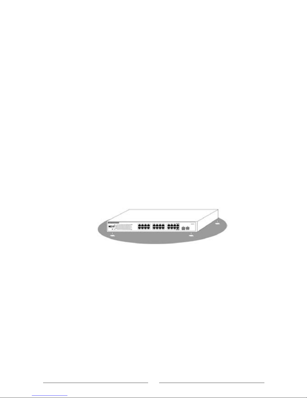
As shown below, attach the four self-adhesive rubber feet
(supplied) to the recessed areas on the bottom of the
switch.
Place the switch on a solid and even surface, near an AC
power source.
Horizontal Installation of
NW223NXT56/NW223NXT57
Rack Installation:
The NW223NXT56/NW223NXT57 structure is suitable
to be mounted in any standard 19-inch rack, using the
supplied L-shape supports.
As shown below, attach the 2 supplied L-shape supports
with the screws on each side of the switch.
After the L supports are attached to the switch, use the
appropriate screws to securely fix the switch onto the EIA
compliant 19-inch rack.
11
•
•
•
•
•
•
Page 13

NW223NXT56/NW223NXT57 L-shape supports (the 24-port
model is used as an example)
Installation of the
NW223NXT56/NW223NXT57
Network connection:
The NW223NXT56/NW223NXT57 supports
10/100/1000 Mbps Ethernet, 10/100 Mbps half/fullduplex mode and 1000 Mbps full-duplex mode. All RJ-45
ports support Auto MDI/MDIX function. They can be
used as ordinary ports or Uplink backbone cascading
ports. Through any RJ45, it is possible to connect work
stations, servers, and other network devices such as
Switches/HUBs.
Furthermore, the NW223NXT56/NW223NXT57
provides 2 shareable SFP fiber modules. Using the
specified Gigabit SFP optical modules and connecting the
corresponding fiber, the Gigabit network can be expanded
up to 80 km, exceeding the limit of the 100 meter range
of the twisted pair network.
12
Page 14

Network transmission media:
RJ45 ports support CAT5/CAT5 or higher category of
STP/UTP cabling. CAT6 UTP cable is recommended to
ensure stable data transmission at 1000 Mbps.
LC fiber connectors are used for the SFP modules.
Caution!
Make sure that only one uplink connection exists
between switches (except for the Trunk function) or
between the switch and HUB, otherwise the multi-uplink
connection could form a loop that makes the entire
network unstable.
13
Page 15
Chapter 3 Configuration
3.1 Fast Login
Since the NW223NXT56/NW223NXT57 is not
equipped with an internal DHCP server, you need to
manually configure the IP address of the computer for
login and configuration. The table below lists the default
parameters of the switch.
You can log in to the setting window of the switch through
the following steps:
a. Connect the switch with the computer NIC interface.
b. Power on the switch.
c. Check whether the IP address of the computer is
within the 192.168.0.xxx range (“xxx” is the integer
between 2~254), for example, 192.168.0.100. For the
IP address setting, refer to Appendix 2.
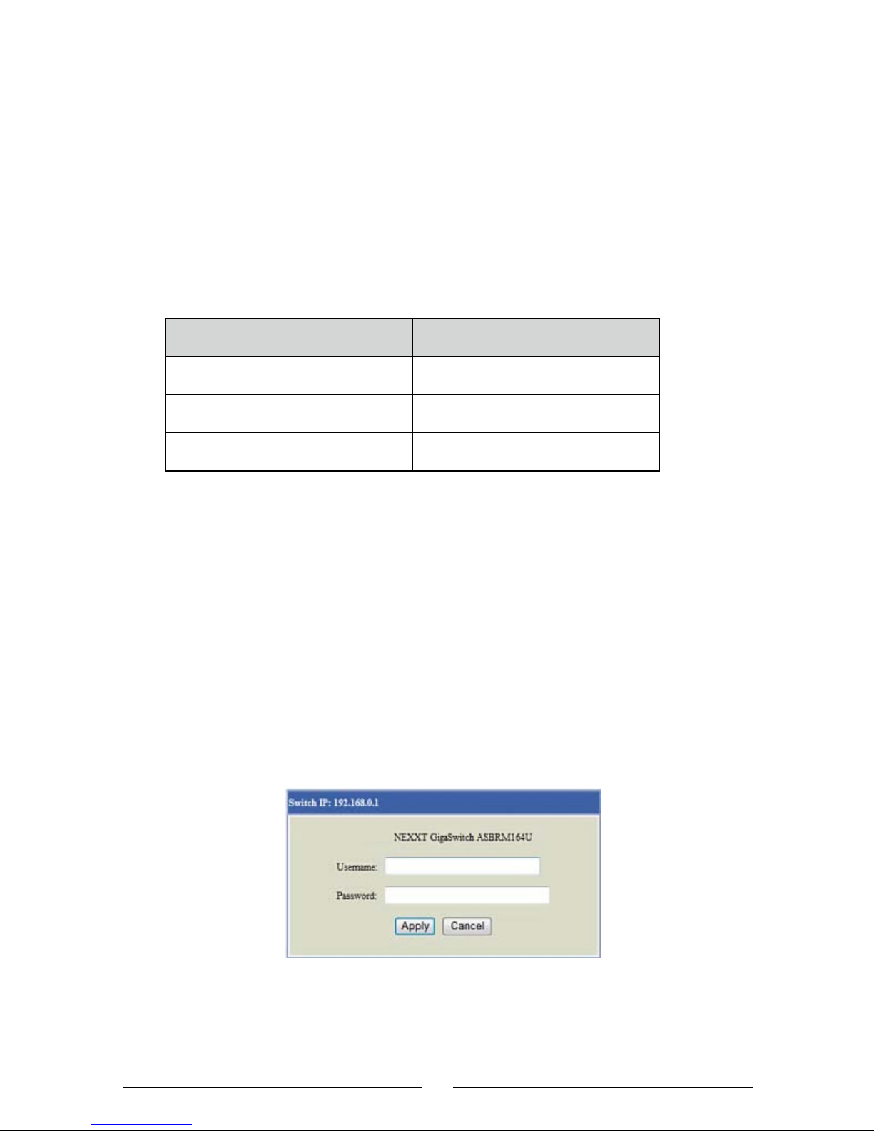
d. Open the browser, and enter http://192.168.0.1;
then press “Enter”. The switch login window appears, as
shown below.
e. Enter the user name and password (both, default user
name and default password are “admin”), and then click
“Apply” to log in to the switch configuration window.
14
Parameter
Default IP address
Default user’s name
Default password
Default Value
192.168.0.1
admin
admin
Page 16
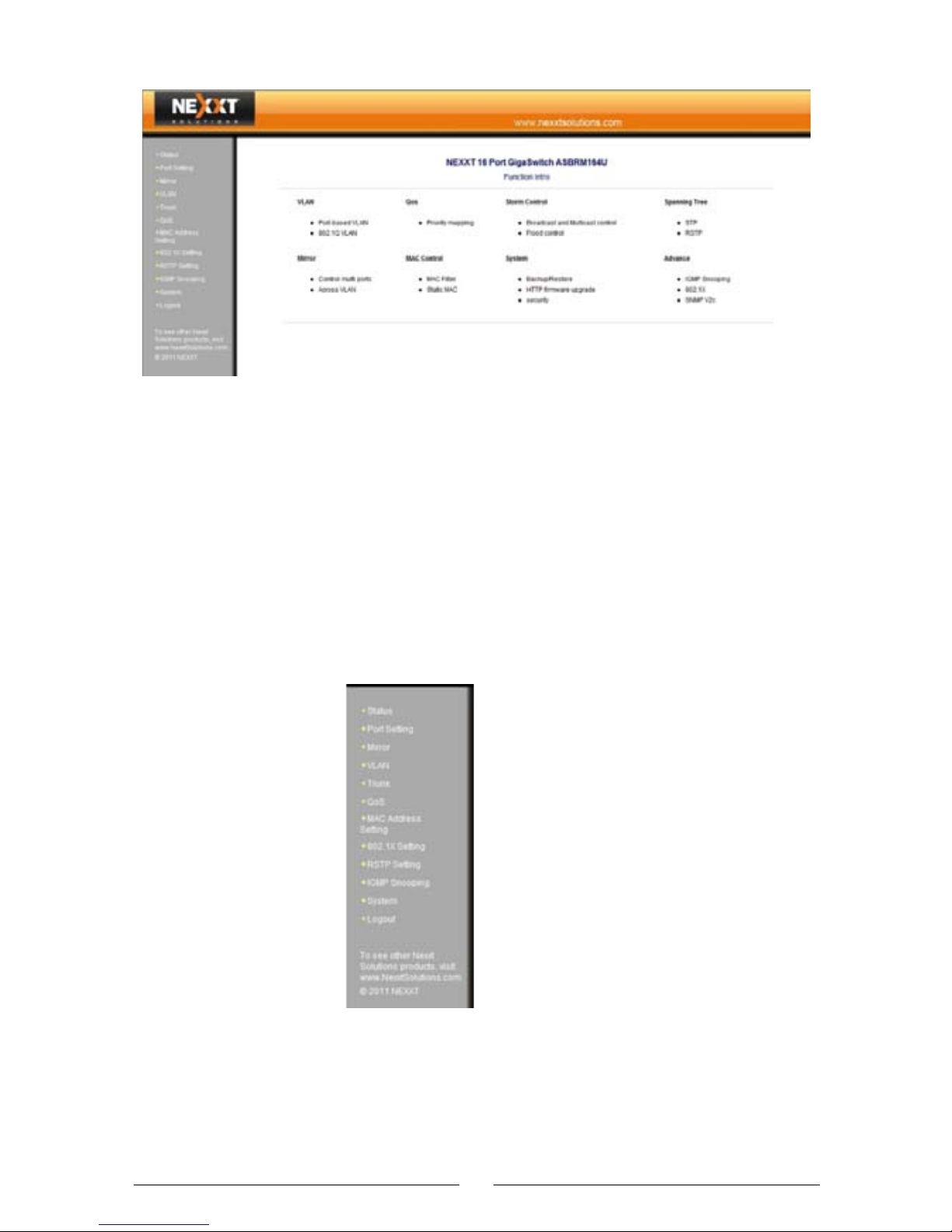
On the left column of the menu bar, you will find “Status”,
“Port Setting”, “Mirror”, “VLAN”, “Trunk”, “QoS”, “MAC
Address Setting”, “802.1X Setting”, “RSTP Setting”,
“IGMP Snooping” and “System”. Click any menu item to
set the corresponding function. The setting procedure will
be described in detail later in this manual.
15
Menu settings
Page 17
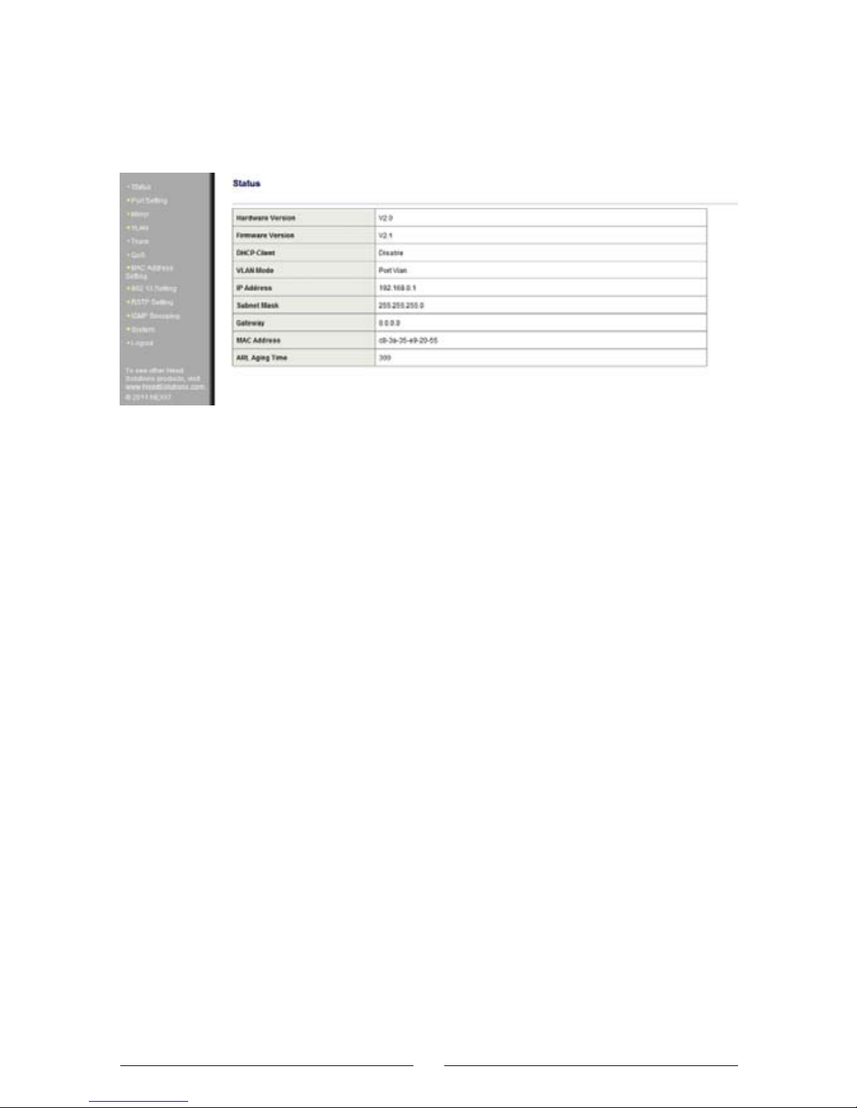
3.2 System Status
The following window displays basic system information.
Hardware Version: Hardware version of the switch.
Firmware Version: Software version of the switch.
DHCP Client: Status of the DHCP client, “Disable” by
default.
IP Address: “192.168.0.1” (default).
Subnet Mask: “255.255.255.0” (default).
Gateway: “0.0.0.0” (default).
MAC Address: MAC address of the switch.
ARL Aging Time: Aging time of the MAC address set,
(Default is 300).
3.3 Port Setting
In the Port Setting window it is possible to set autonegotiation, speed, duplex, flow control modes for each port.
Every port can be set as follows: 10M half-duplex, 10M
full-duplex, 100M half-duplex, 100M full-duplex, 1G
full-duplex, auto-negotiation. Some devices are not able to
negotiate the speed and operating mode (e.g. some
media converters). In that case, configure the speed
according to the device.
By default, port speed is auto-negotiated, so that it is
possible to choose the best work mode after negotiating
16
•
•
•
•
•
•
•
•
Page 18
with the corresponding device. Flow control is used to set
the data flow and prevents the buffer overflow of the
receiving device. The port management setting will affect
port bandwidth control, port mirroring and trunking
functions.
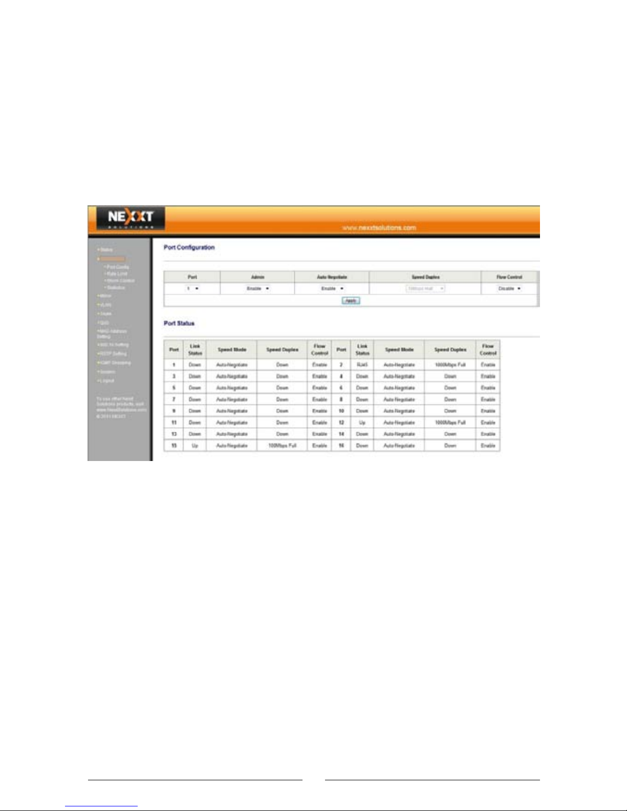
3.3.1 Port
Port configuration: Only the ports belonging to the same
VLAN group can communicate together; a port can
belong to more than one VLAN group and communicate
with multiple VLAN groups at the same time.
The configuration of the basic functions of the switch
include: port enable/disable, operating mode and flow
control.
The following section describes the configuration details:
Port: Allows the selection of the corresponding port
number 16/24 and the setting of network speeds of
10/100/1000 Mbps, either in half or full duplex modes.
Admin: Enable or disable the traffic on the corresponding
port. (Caution: Do not disable the ports unless it is
17
•
•
Page 19
necessary).
Auto Negotiate: Enable or disable the auto negotiation
function of the port.
(Caution: You must “Disable” the Auto negotiation function
before selecting the “Duplex/Speed” setting).
Duplex/Speed: Allows the selection of the 10 Mbps
full-duplex and half-duplex mode, 100 Mbps full-duplex and
half-duplex mode or 1000 Mbps full-duplex mode for the
port.
Flow Control: Supports the IEEE802.3x full-duplex flow
control and half-duplex backpressure flow control (switch
can change its flow control mode to its port duplex mode
automatically).
Port Status: Lists the current setting status details of all
ports, as shown below.
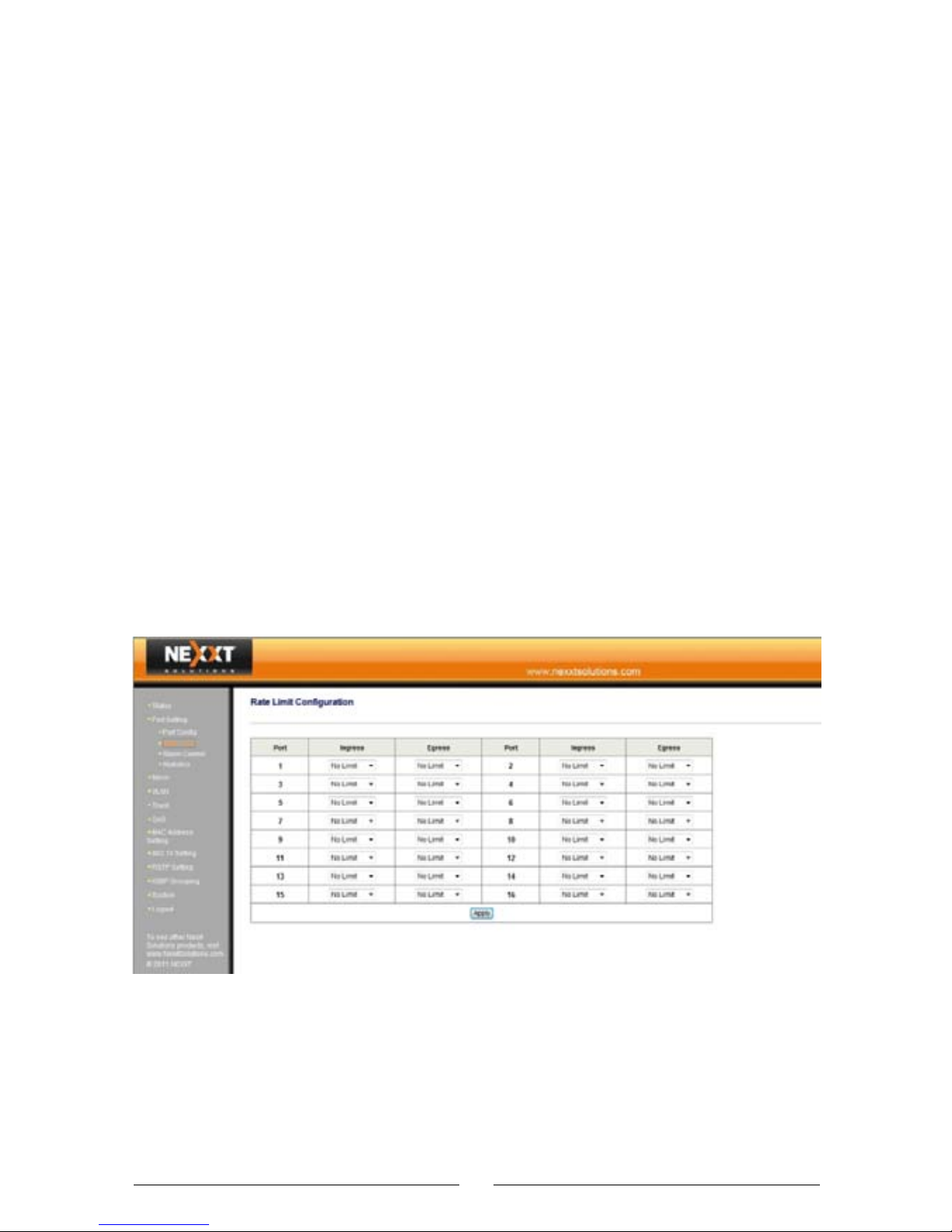
3.3.2 Rate Limit
Rate Limit Configuration: This option is intended to limit
the receiving rate of each port, to prevent the user from
occupying excessive bandwidth. In this way, you can
ensure a smooth connection as well as regular use by
other members connected to the network. This function
18
•
•
•
Page 20
is applicable to the Internet bar and community broadband access applications.
Port: Allows the selection of the corresponding port
number 16/24 and the setting network speeds of
10/100/1000 Mbps, either in half or full duplex modes.
Policer: Controls the receiving rate by level. Available
rates are: 128 Kbps; 256 Kbps; 384 Kbps; 512 Kbps;
640 Kbps; 768 Kbps; 896 Kbps; 1024 Kbps; 1152
Kbps; 1280 Kbps; 1408 Kbps; 1536 Kbps; 1664 Kbps;
1792 Kbps; 1920 Kbps; 2048 Kbps; 2176 Kbps; 2304
Kbps; 2432 Kbps; 2560 Kbps; 2688 Kbps; 2816 Kbps;
2944 Kbps; 3072 Kbps; 3200 Kbps; 3328 Kbps; 3456
Kbps; 3584 Kbps; 3712 Kbps; 3840 Kbps; 3968 Kbps;
No Limit.
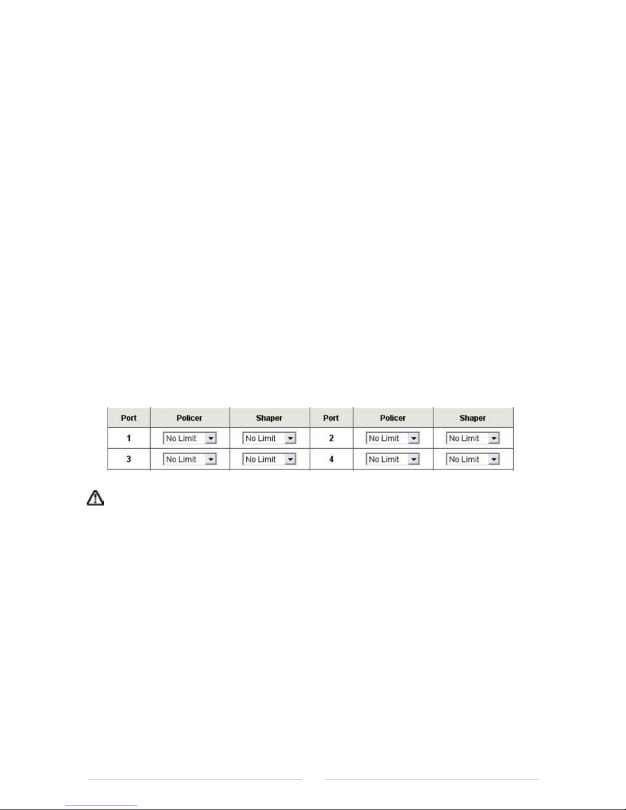
Shaper: Displays the bandwidth control status of each
port, as shown below.
Caution: If the selected rate is higher than the actual
connection rate for that port, the display will show the
selected value instead of the actual speed being used.
19
•
•
Page 21
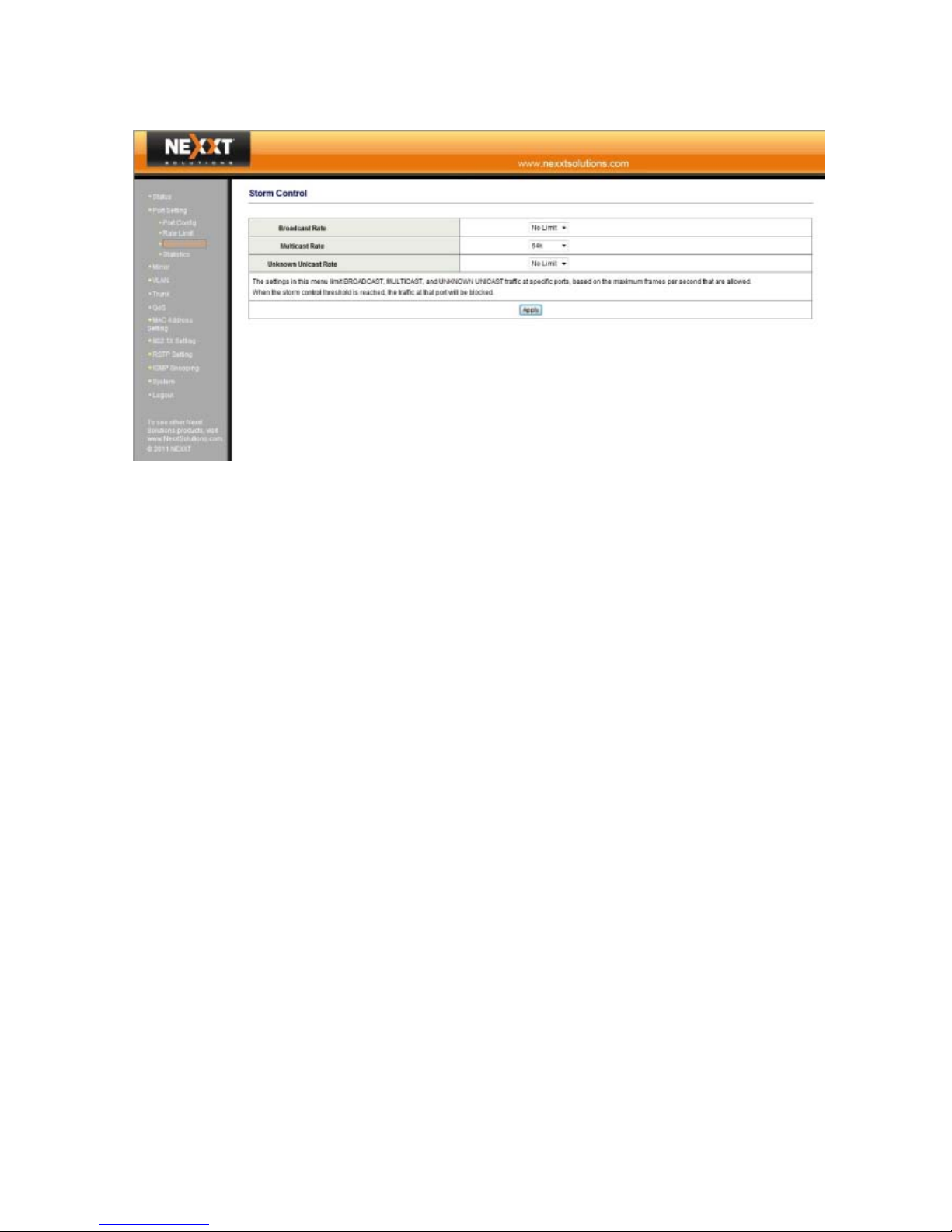
3.3.3 Storm Control
Storm Control: Also known as traffic suppression, this
feature selectively blocks the transfer of broadcast
packets from the switch. When different types of
broadcast packets reach the set threshold of a port, the
switch automatically discards excessive packets, to
prevent being disrupted by a broadcast, multicast, or
unicast traffic storm on physical interfaces.
Observations
1. Broadcast means transmitting packets to all hosts in
the network.
2. Multicast means transmitting packets to a host group
in the network.
3. Unicast means transmitting packets to a specific host
in the network.
4. Unknown unicast (flood) means transmitting the
unicast packets with an unknown destination MAC
address.
5. The switch is unable to totally control broadcast
packets. Instead,it can only limit the transmitting rate for
broadcast packets.
20
Page 22
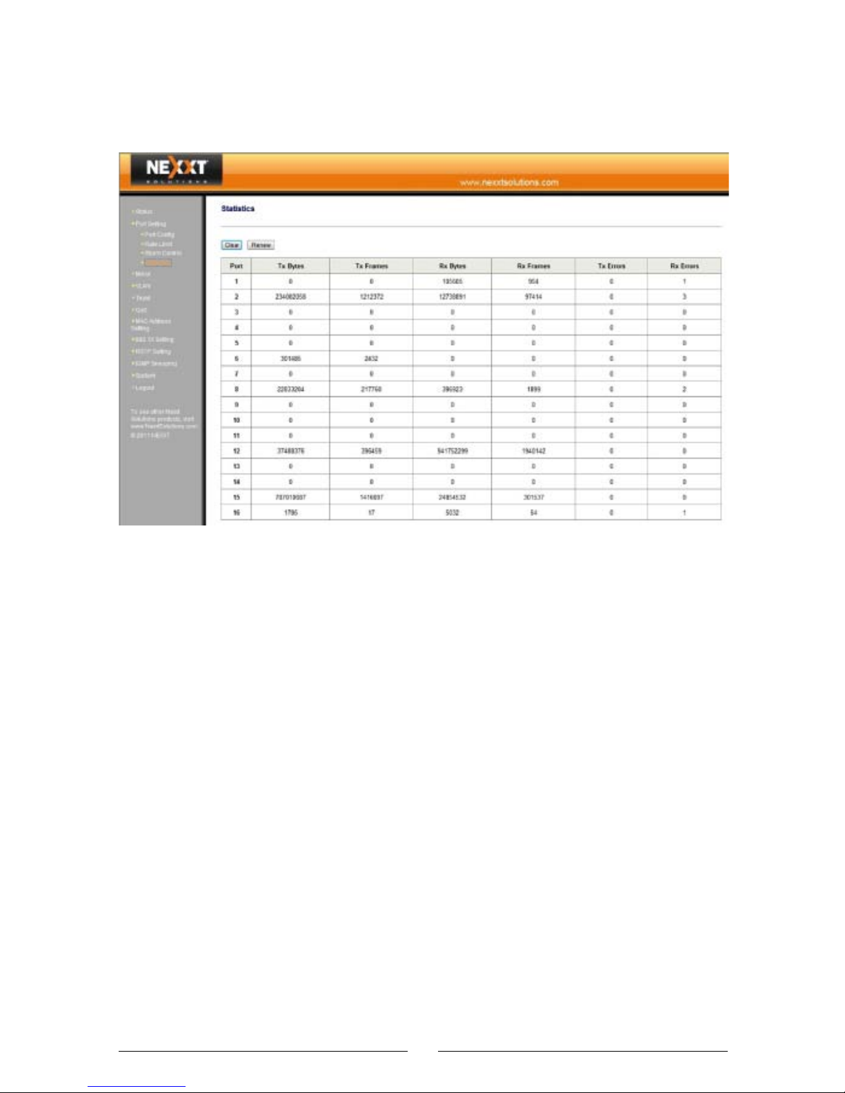
3.3.4 Statistics
Statistics: Displays the currently received and
transmitted data, including the number of error frames
at each port.
Clear button: Use this button to erase all the counter
values.
Renew button: Use this button to refresh statistical data.
21
•
•
Page 23
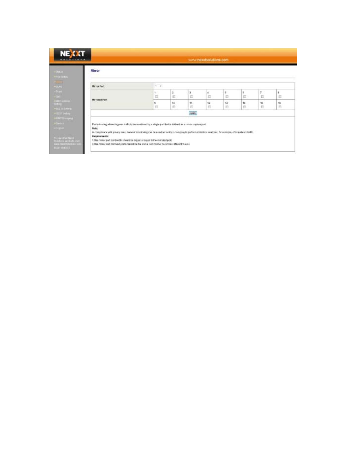
3.4 Mirror
Mirror function is used to duplicate the traffic from one
or more mirrored ports to a mirror port; this function is
used to monitor the internet access.
If the mirror and mirrored ports are the same, the
system will automatically ignore this mirrored port.
Mirror port bandwidth should be bigger or equal to the
mirrored port bandwidth.
This function supports cross-VLAN monitoring. If the
mirrored port and the mirror ports are assigned to
different VLAN groups, the mirror function is allowed.
Mirror:
Mirror Port: Selects the port to be used as the monitor
port.
Mirrored Port: Selects one or more ports to be
monitored.
3.5 VLAN
To establish secure autonomous broadcast/multicast
domains, you can make switch ports form VLANs. The
VLAN technology can be used to divide a network into
multiple network segments, and reduce broadcast
domains. All Ethernet packets, such as unicast,
22
•
•
•
•
Page 24
multicast, broadcast and unknown unicast packets, are
to be transferred only within the VLAN. In addition, VLAN
can be used to change the topological structure of the
network, without any movement of network workstations
or change of network connections. You can modify the
VLAN setting of a workstation, to “move” this workstation
from a VLAN (VLAN of the Sales Dept.) to another VLAN
(for example, VLAN of the Marketing Dept.). In this way,
the network nodes can be moved, changed or added in
an extremely flexible and easy way.
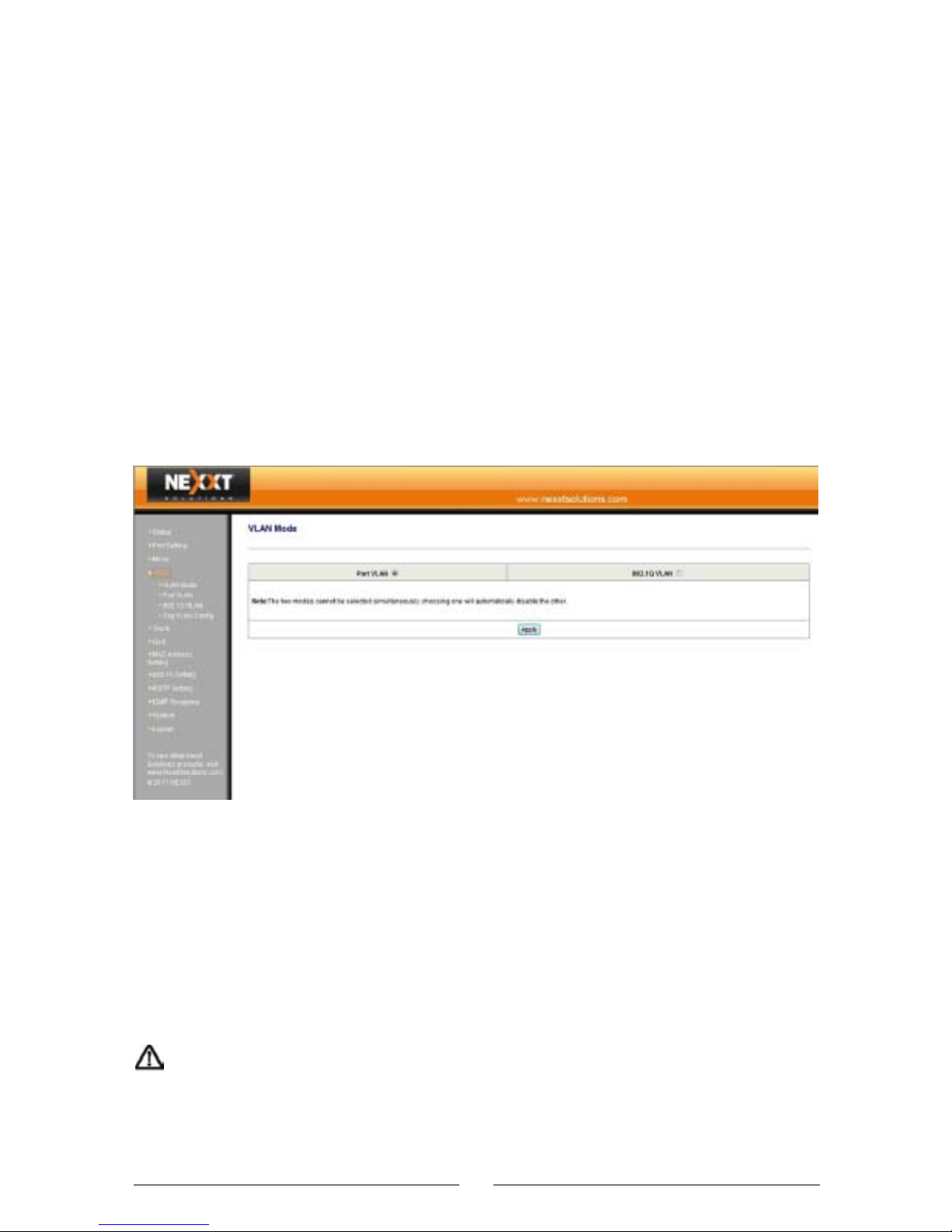
3.5.1 VLAN Mode
Two VLAN modes are available: Port VLAN and 802.1Q
VLAN.
Port VLAN: Select this option and then click on “Apply”,
to set the port VLAN mode.
802.1Q VLAN: Select this option and then click on
“Apply”, to set the 802.1Q VLAN mode.
Note: If a VLAN mode is selected, any other mode will
be automatically disabled.
23
•
•
Page 25
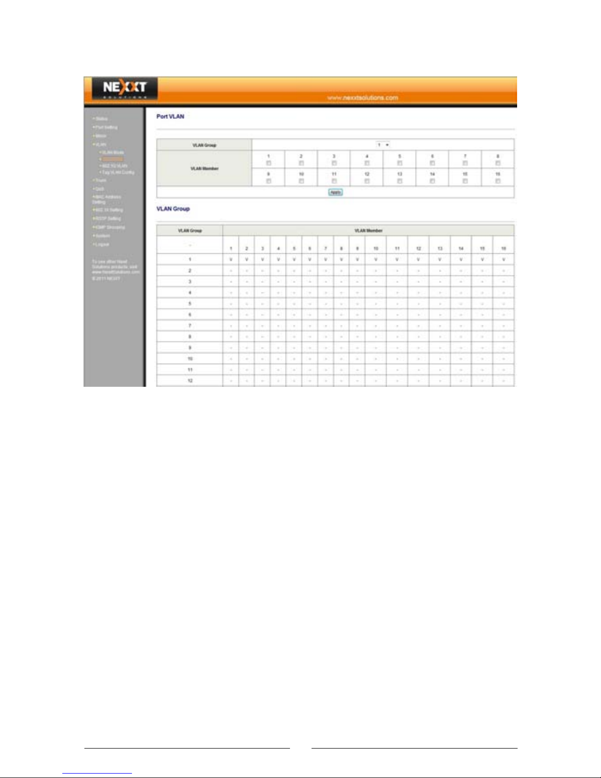
3.5.2 VLAN Port
Description of VLAN Port configuration: A port based
VLAN uses the physical ports of the switch to distinguish
VLANs.
VLAN Group: Includes all 16/24 ports. Default VLAN
has a VLAN ID of 1.
VLAN Member: Adds the physical ports of the switch to
be included in this VLAN.
24
•
•
Page 26
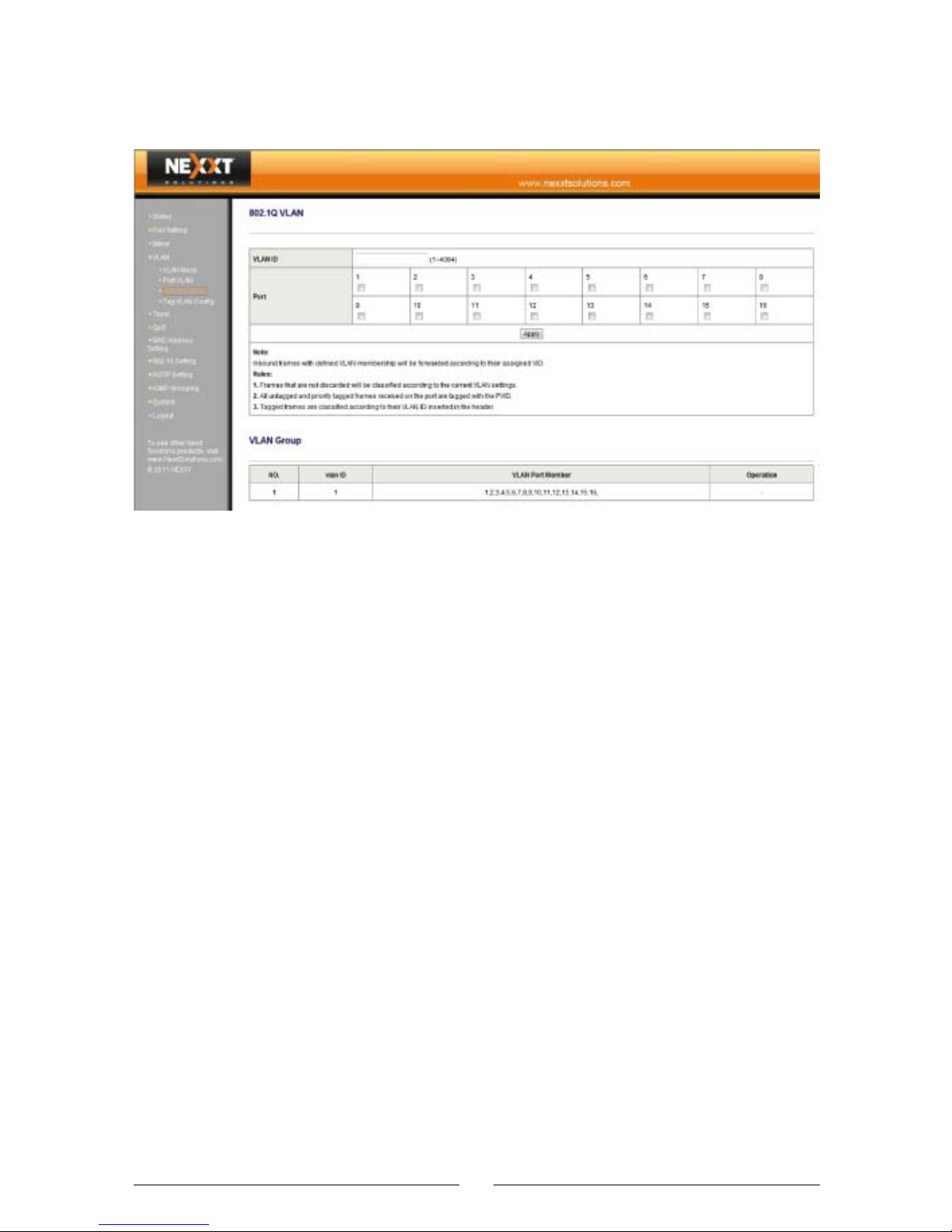
3.5.3 802.1Q VLAN
Description of 802.1Q VLAN configuration:
In the VLAN Tag mode, port VID is used to identify a
particular VLAN. When data frames pass through the
switch, the VID tag uses the frame header to define the
different VLANs, so the switch can determine the
destination ports of such frames according to the current
VLAN settings.
VLAN ID: It includes all 16/24 ports. Default VLAN has a
VLAN ID of 1. The VLAN ID 1 attributer cannot be edited.
Port: Choose the ports to be assigned into the current
VLAN ID.
25
Page 27
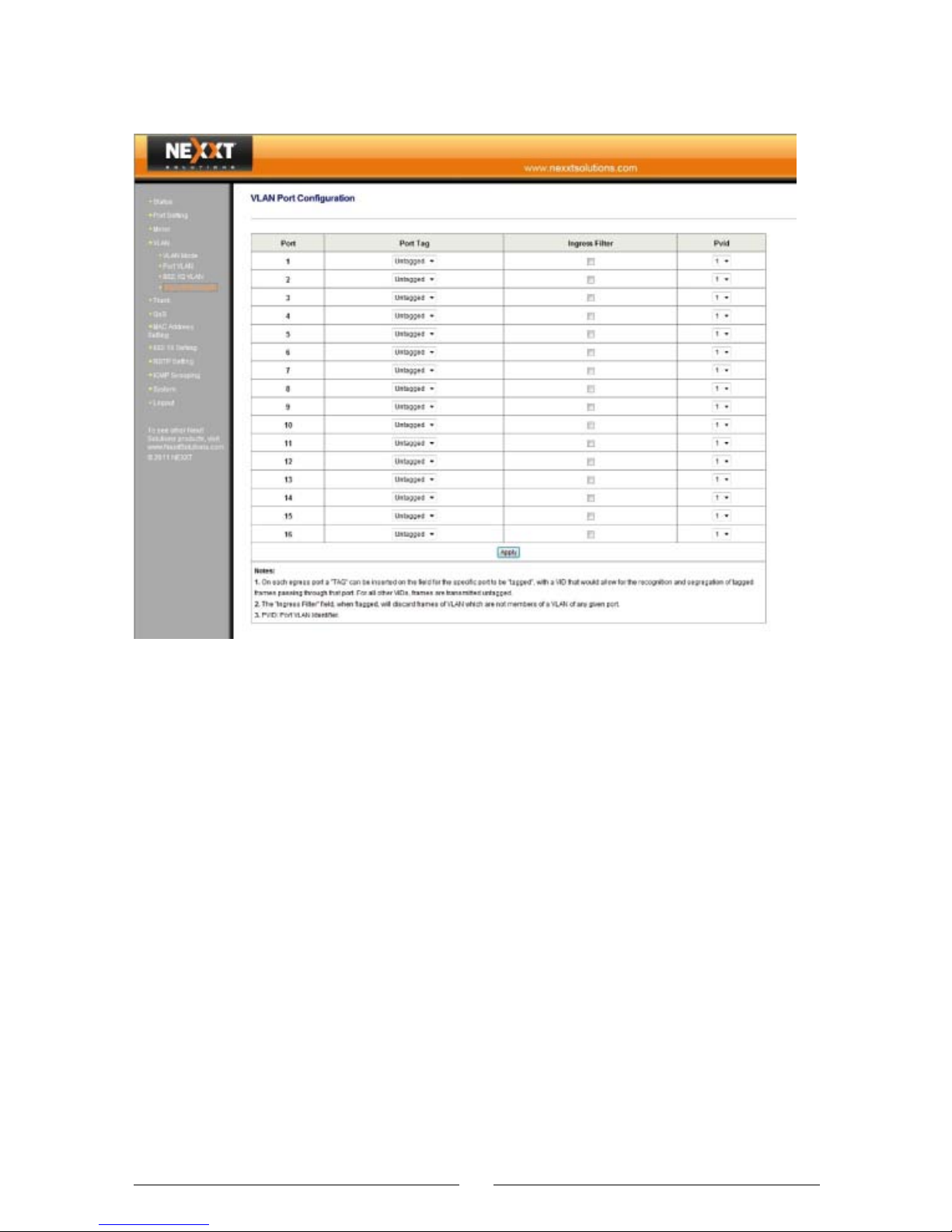
3.5.4 Tag VLAN Configuration
Description of 802.1Q VLAN port configuration:
Port Tag: Sets the Tag attributes for the port. The port
Tag rule specifies the changes to be made upon the
frame output, that is, the egress rule. The available rules
are “add” or “remove” Tag.
Ingress Filter: Specifies the ingress filtering rule, which
determines the reception or rejection of Tag messages
inconsistent with the port Pvid.
Pvid: Sets the VLAN ID of this port.
26
•
•
•
Page 28
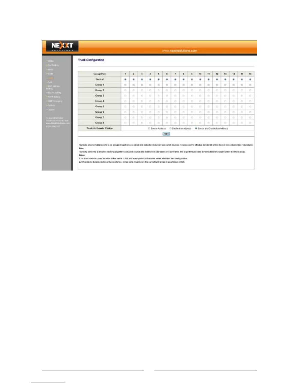
3.6 Trunk
Trunk is used to expand the bandwidth (e.g. hot backup
and error tolerance of the inter-switch cascading the
Uplink channels).
All ports set as the trunk group members can be used by
the trunk group only and cannot be used for any other
purpose, even when they are not being used by the trunk
group.
Cross-VLAN trunk groups are not supported. In other
words, all members of a trunk group must be within the
same VLAN; otherwise, the trunk function cannot work.
When the trunk group is used for the inter-switch
cascading, make sure the cascading port used for
connecting with the other switch is set to the same trunk
group.
Never connect two trunk groups of a switch together or
cascade two switches through two groups of trunk
channels, because such operations result in a network
loop. This situation could cause a broadcast storm or
even a breakdown in the entire network.
27
•
•
•
•
•
Page 29
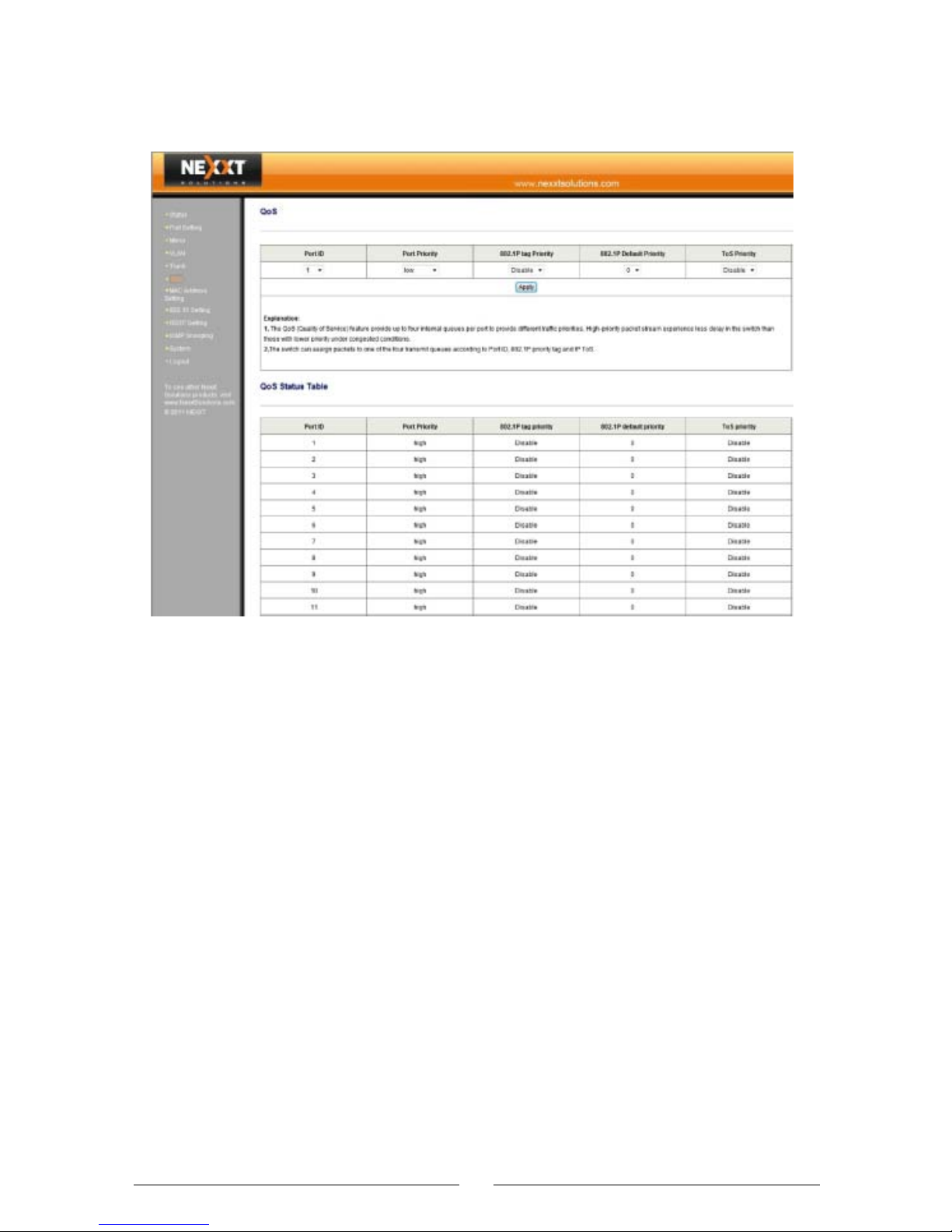
3.7 QoS
Simple QoS functions can be implemented through the
combination of priority mode settings and priority control
operations. This switch supports packet mapping by 4
priority levels (low, medium, common, and high) and 3
priority setting modes.
28
•
Page 30
If “Port Priority” is enabled and a high priority is assigned
to a physical port, all packets passing through this port
are mapped into high priority. As a result, the switch
processes the received/transmitted packets through this
port first.
If “802.1Q tag Priority” is enabled, the switch automatically reads the 3-bit priority tag from the packet with a
VLAN tag. And if such a priority tag indicates a high
priority, this packet is mapped into high priority. In this
way, when the switch gets faulty, it will process packets
transmitted by this port first.
If “ToS Priority” is enabled, the switch automatically reads
the 8-bit ToS tag from the IPv6/IPv4 packet. And if such
a priority tag indicates a high priority, this packet is
mapped into high priority for priority processing.
Description of QoS configuration:
Port ID: Select the port to be set.
Port Priority: Select “low”, “common”, “medium” or
“high”.
802.1P tag priority: Enabled or disabled.
ToS priority: Enabled or disabled.
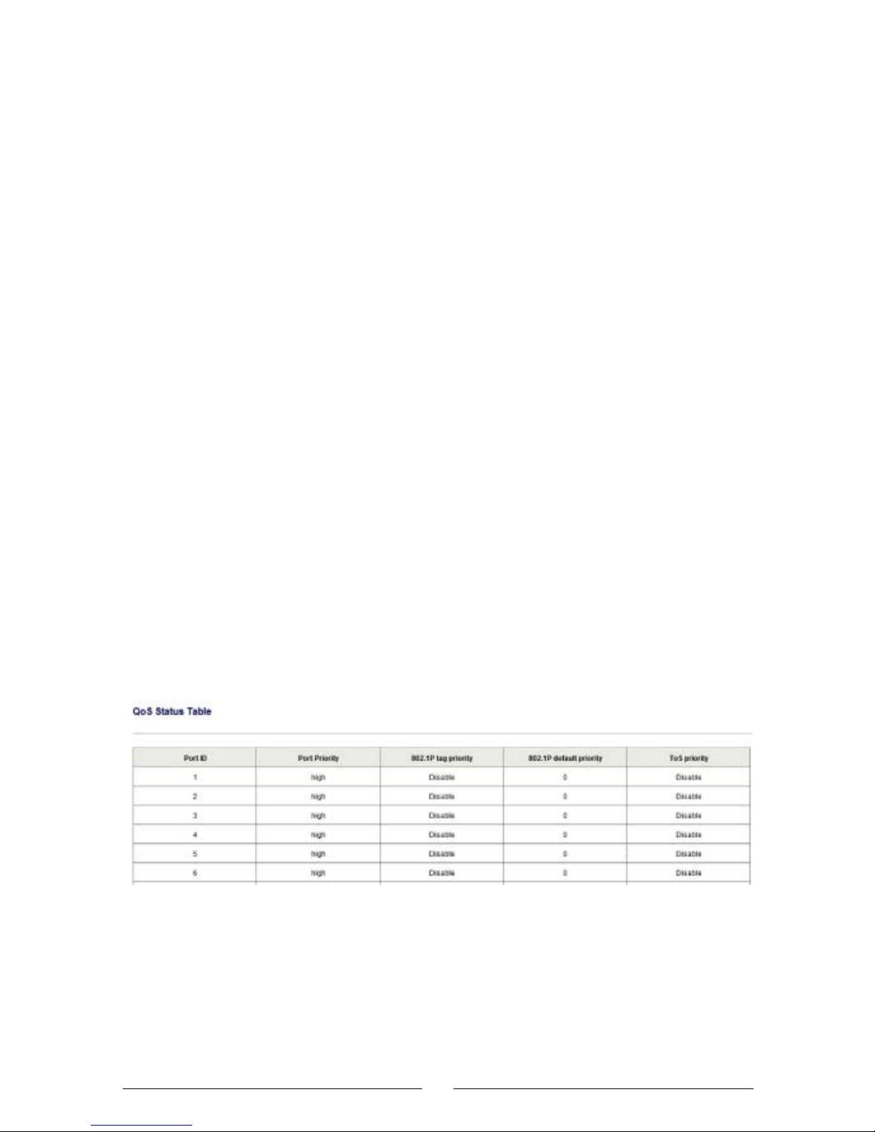
QoS Status Table: Displays the status of all ports.
29
•
•
•
•
•
•
Page 31
3.8 MAC Address Setting
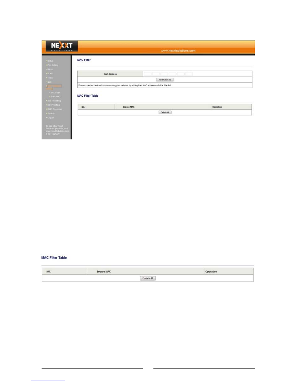
3.8.1 MAC Filter
MAC Filter: The MAC address filter is the “black list” of
the switch. These MAC addresses are cut out from the
network communication when they are connected to any
port on the switch.
MAC Address: Enter the MAC address to be filtered.
MAC Filter Table: List the MAC addresses filtered, as
shown below. You can click “Delete” on the right to erase
the corresponding MAC address that has been filtered.
30
Page 32
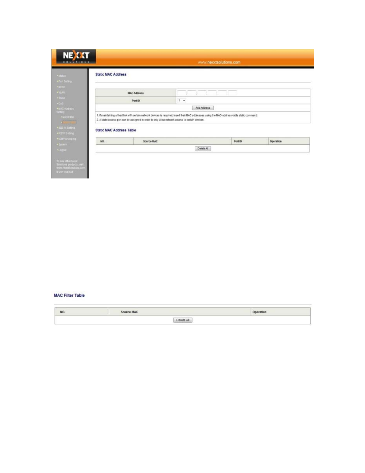
3.8.2 Static MAC
Static MAC Address: Adding a MAC address to the
appointed port, the bundled MAC address will transfer
data only through this port.
MAC Address: Insert the MAC address.
Port ID: Choose the port to be bundled.
Static MAC Address Table: List the bound MAC addres-
ses, as shown below. You can click “Delete” below to
erase the corresponding bound MAC address.
3.9 802.1X Setting
As an authentication protocol, 802.1X provides methods
and policies for authenticating users. It is a port-based
authentication policy, which gives access to a specific
port. If “enabled" after a successful authentication, it will
allow for the transmission of all messages; if “disabled”
after a failed port authentication, it will only allow the
transmission of 802.1X authentication messages.
31
•
•
Page 33
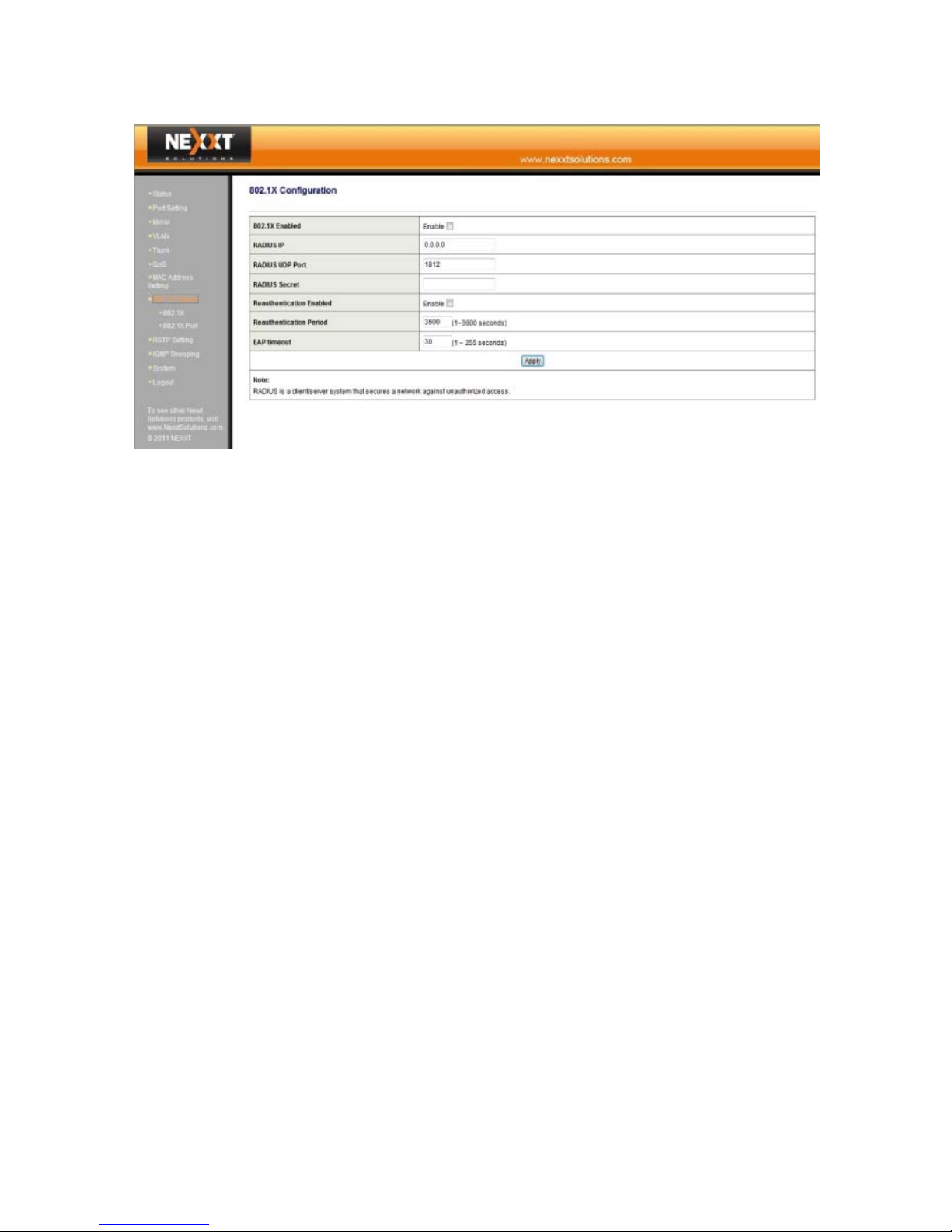
3.9.1 802.1X
802.1X Configuration:
802.1X Enabled: Enables or disables the 802.1X
authentication feature.
RADIUS IP: Sets the IP address of the RADIUS server.
RADIUS UDP Port: Sets the RADIUS UDP port of the
switch; the default value is 1812.
RADIUS Secret: Sets this value according to the secret
key corresponding to the RADIUS.
Reauthentication Enabled: Enables or disables the
reauthentication feature.
Reauthentication Period: Sets the cycle of reauthentication, the default value is 3600 seconds.
EAP timeout: Sets the timeout interval of the EAP
response, the default value is 30 seconds.
32
•
•
•
•
•
•
•
Page 34
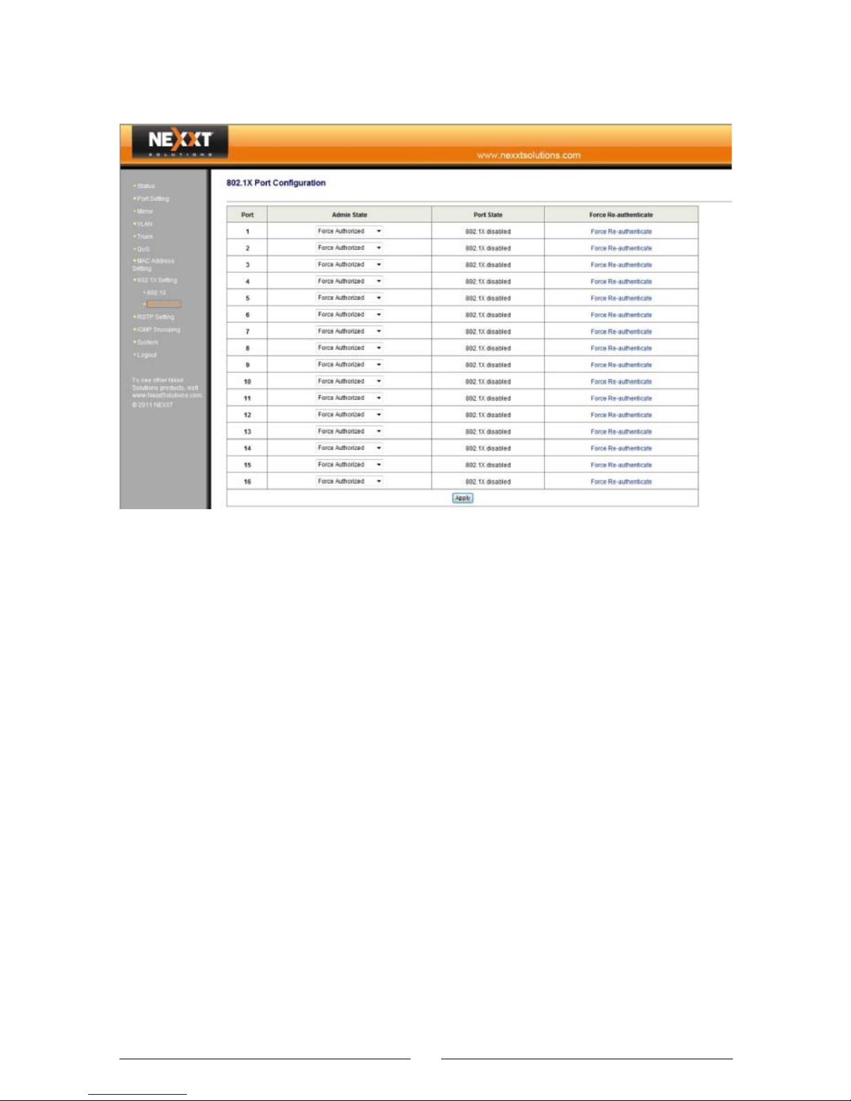
3.9.2 802.1X Port
802.1X Port Configuration
Admin State: Choose between:
• Force Authorized: allows transmission of
any message.
• “Force Unauthorized”: allows transmission of
authentication messages.
• “Auto”: allows the transmission of certain
messages according to the authentication
result.
Port State: 802.1X disabled; Link interrupted; Authorized; Unauthorized.
Force Re-authenticate: Click on the corresponding port
to perform a forced reauthentication procedure.
3.10 RSTP Setting
RSTP can be used to create connection links for redundancy backup. You can change the RST parameters at
33
•
•
•
Page 35
the bridge level. In view of the high complexity of the
RSTP algorithm, it is recommended to accept the default
values. RST automatically assigns root bridge or root
port, to prevent a loop condition. However, if modification
to RST parameters is necessary, you should carefully
read the related RSTP contents to understand them in
advance.
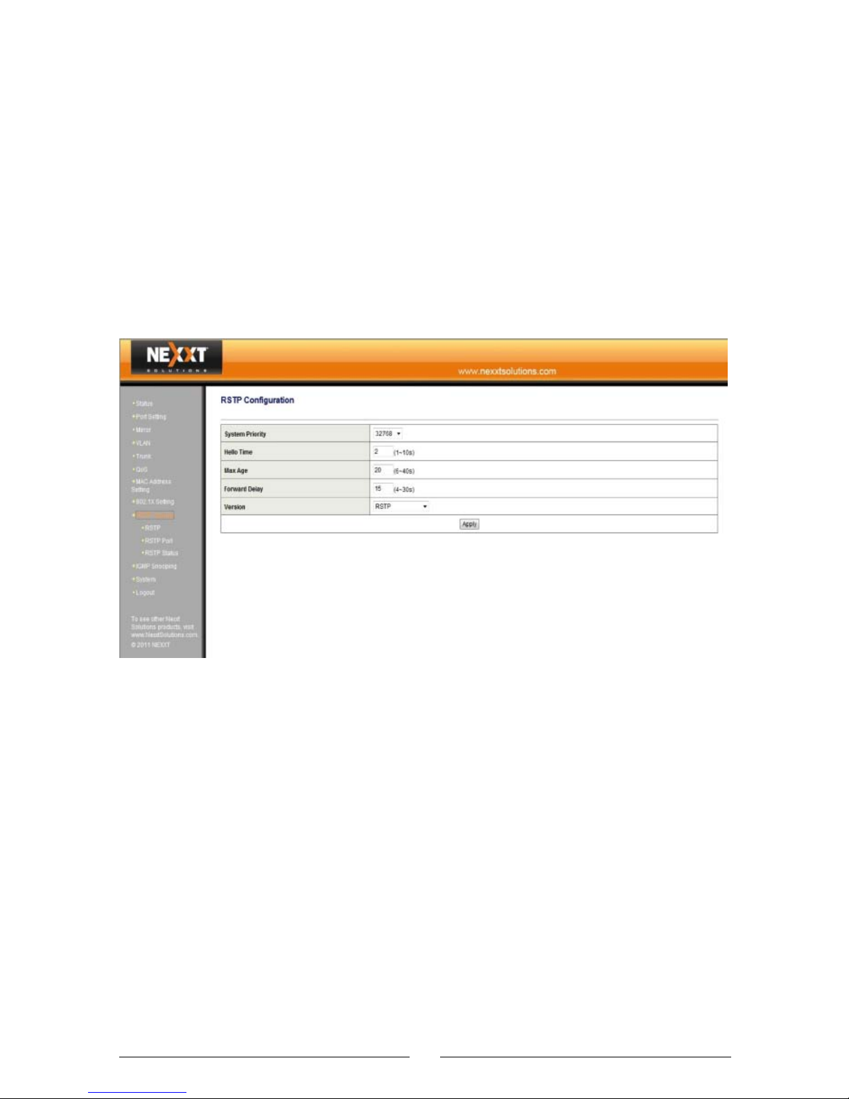
3.10.1 RSTP
RSTP Configuration:
System Priority: Sets the system priority of the switch in
the RSTP. A switch with a lower system priority is easier
to make the root bridge. If the switch is used in a
large-scale workgroup-class network, it is recommended
to skip this setting.
Hello Time: Sets the value between 1 sec and 10 sec.
This represents the time interval the root bridge uses to
transmit BPDU packets to the rest of the switches, so
that they are able to detect which switch is serving as
the root bridge. This value does not take effect if the
34
•
•
Page 36
switch is not set as a root bridge. If a switch becomes a
root bridge, this value will take effect.
Max Age: Sets a value between 6 sec and 40 sec.
Indicate that the time limit of the last BPDU received is
valid. Switch with the lowest bridge tag level that does
not receive the BPDU packet transmitted by the root
bridge when this maximum aging time is up, as it will
serve as the root bridge and transmit the BPDU packets
to all other switches. Therefore, you should select a big
value, to avoid the unnecessary repeated resetting of
root bridges.
Forward Delay: Sets a value between 4 sec and 30 sec.
This setting represents the monitoring time for transitioning the switch port from blocking status to forwarding
status. A bigger setting will result in a longer delay.
Version: Select RSTP based on 802.1W (default value)
or STP based on 802.1D.
3.10.2 RSTP Port
35
•
•
•
Page 37
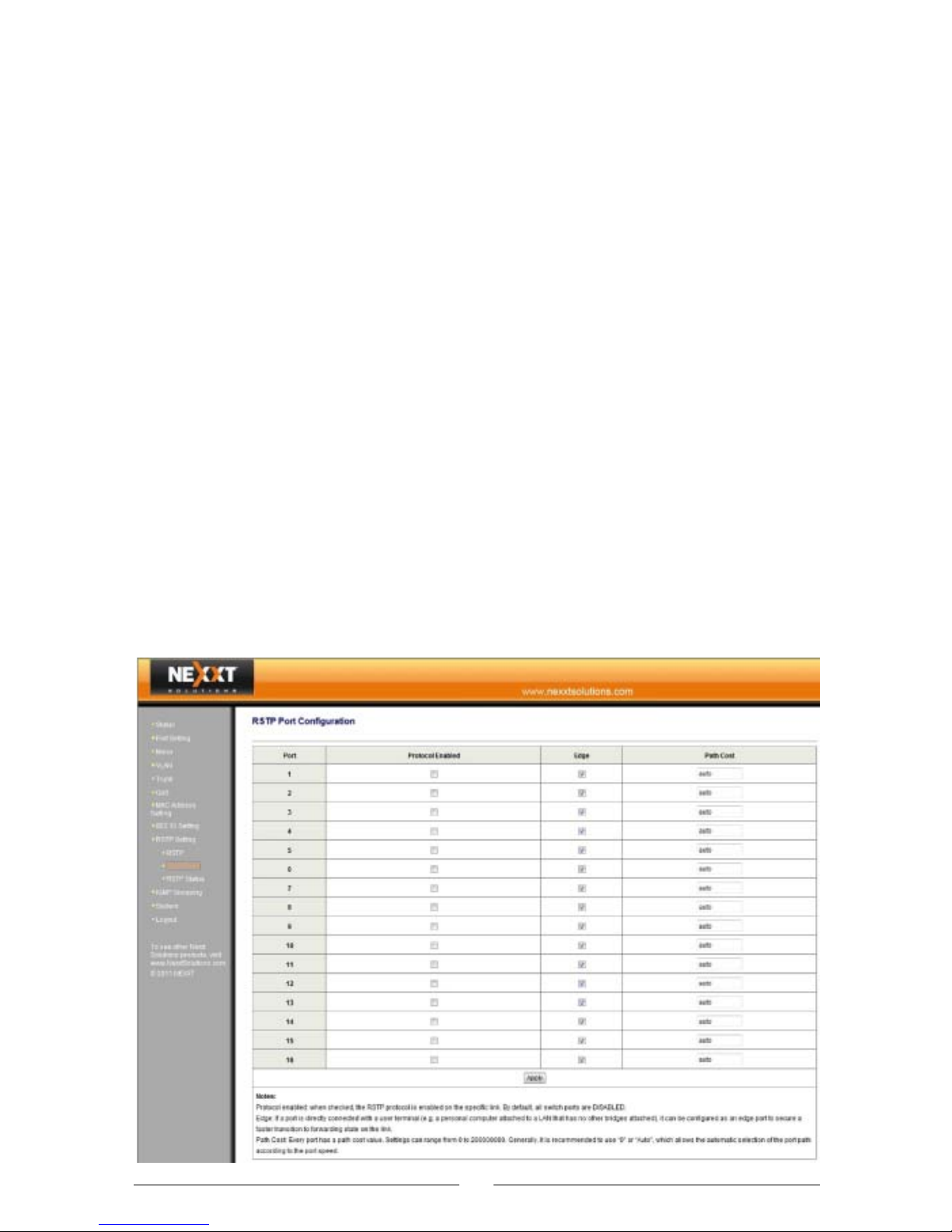
RSTP Port Configuration:
Protocol Enabled: Enables or disables the RSTP feature.
By default, this function is disabled for every port.
Edge: The edge port feature has faster status transition,
and it is 2 times faster than the forwarding delay when it
directly changes from blocking to forwarding status. If a
port is directly connected with the terminal, you can set
this port as an edge port.
Path Cost: Every port has a path cost value. The cost is
typically based on a guideline established as part of
802.1d. According to the original specification, cost is
1,000 Mbps (1 gigabit per second) divided by the
bandwidth of the segment connected to the port.
Therefore, a 10 Mbps connection would have a cost of
(1,000/10) 100. The path cost can be an arbitrary
value assigned by the administrator, instead of one of the
standard cost values. If set to auto, it will automatically
determine the port path cost depending on the port rate.
3.10.3 RSTP Status
36
•
•
•
Page 38

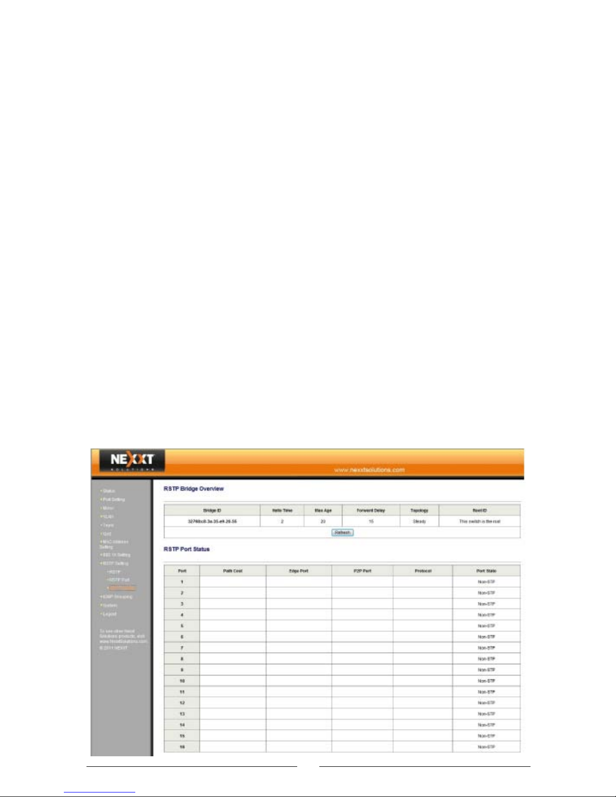
RSTP Bridge Overview: Displays the bridge ID, topology
and root bridge ID specified by the system, including Hello
time, maximum aging time and forwarding delay setting.
RSTP Port Status: Displays the P2P port, protocol and
port state specified by the system, including path cost
and edge port settings.
3.11 IGMP Snooping
IGMP Snooping is used to implement dynamic registration
of L2 multicast on the switch. To achieve L2 multicast
through the IGMP Snooping function, you need to make
sure IGMP protocol is implemented on the host and
router side. The switch only snoops into different types of
IGMP messages transmitted by the host and router, to
dynamically maintain the L2 multicast group. Usually,
multicast registration on this switch does not affect the
setting of other switches. The switch transmits the IGMP
query message and receives the IGMP response from the
host. Based on the receiving port, VLAN ID and multicast
of such IGMP packets, the switch maintains a multicast
group. After that, it forwards such IGMP packets. Only
the ports included in a multicast group can receive the
multicast data stream. In this way, the network traffic is
reduced and network bandwidth is saved.
37
•
•
Page 39
3.11.1 Snooping Configuration
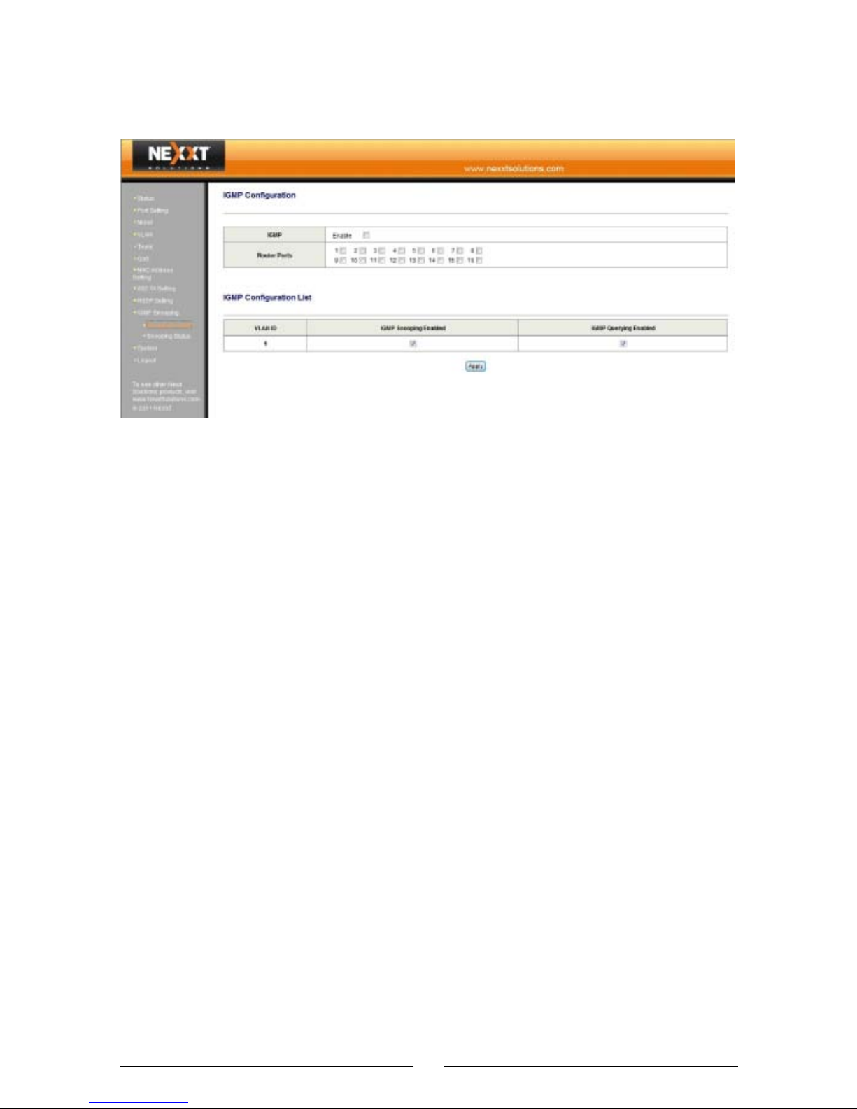
IGMP Configuration
IGMP: Enables or disables the L2 multicast snooping
function of the switch. By default, this option is not
checked.
Router Ports: Selects the IGMP routing ports for
multicast snooping.
IGMP Configuration List:
IGMP Snooping Enabled: Enables or disables the L2
multicast snooping function of the switch of the corresponding VLAN.
IGMP Query Enabled: Enables or disables the IGMP
query. Once this function is enabled, you can view the
multicast snooping status of the corresponding VLAN in
Snooping Status.
38
•
•
•
•
Page 40
3.11.2 Snooping Status
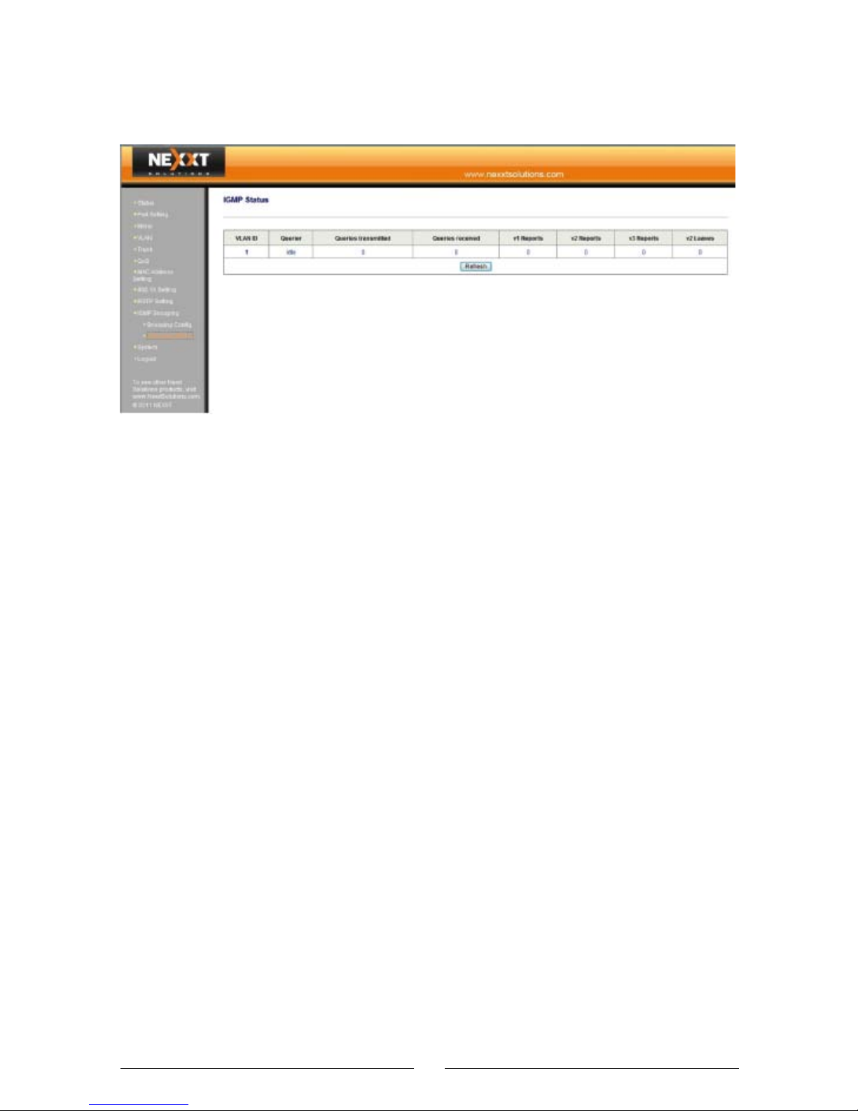
IGMP Status: Displays the multicast snooping function
options of the corresponding VLAN. When the multicast
table is not established, the “Querier” displays as “Idle”.
When the switch snoops into a multicast message, the
“Querier” displays as “Active”, and the value in “Queries
transmitted” or “Queries received” may change at the
same time. By changing the values in “V1 Reports”, “V2
Reports” and “V3 Reports”, it is possible to know the
corresponding version of the multicast messages
received. If a message is of V2 and a device in the
multicast table is required for leaving the multicast group,
the leave message is transmitted.
Refresh: Use this button to manually refresh current port
status information.
39
•
Page 41
3.12 System
3.12.1 SNMP
All management information and counters are stored in
the Management Information Base (MIB) of the switch.
Usually, the switch adopts the standard MIB-II module,
able to be read by any SNMP-based NMS software. MIB
data may be of either read-only or read-write mode.
You can change the default SNMP community names of
the switch and set access right for such community
names.
Trap is used for the notification of certain events on the
switch. Such events may be serious (for example, switch
reboot) or ordinary (for example, the status change of a
switch port). The switch can generate a trap and send it
to the NMS.
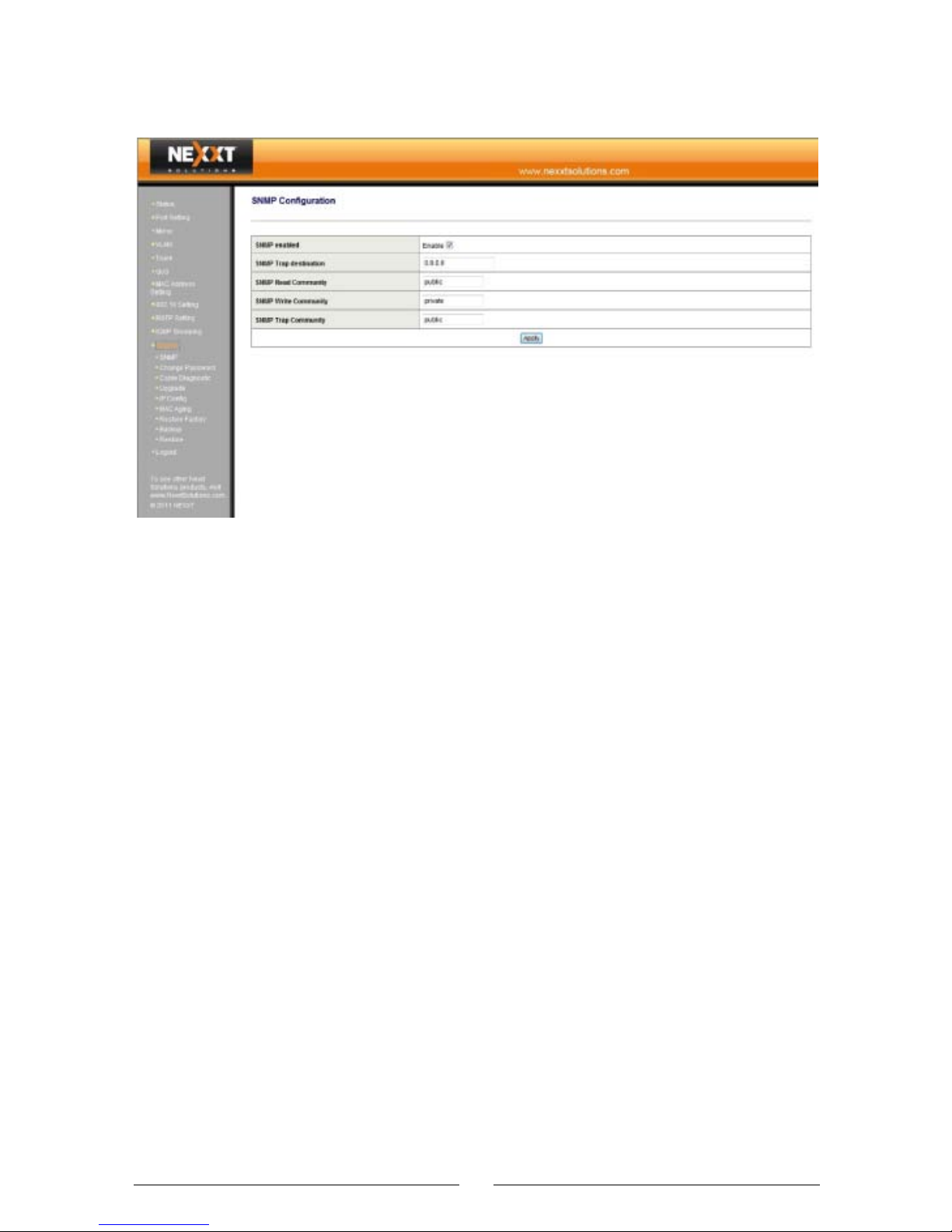
SNMP Configuration:
SNMP enabled: Enables or disables the SNMP manage-
ment function.
SNMP Trap destination: Sets the destination IP address
of the Trap message of the switch.
40
•
•
Page 42
SNMP Read Community: Sets the read-only community
name of the SNMP information of the switch. To read the
SNMP information of the switch, the SNMP management
software must contain the consistent read-only community name.
SNMP Write Community: Sets the writeable community
name of the SNMP information of the switch. To modify
the SNMP information of the switch, the SNMP management software must contain the consistent writeable
community name.
SNMP Trap Community: Used by the SNMP management software to identify the specific switch sending the
Trap message.
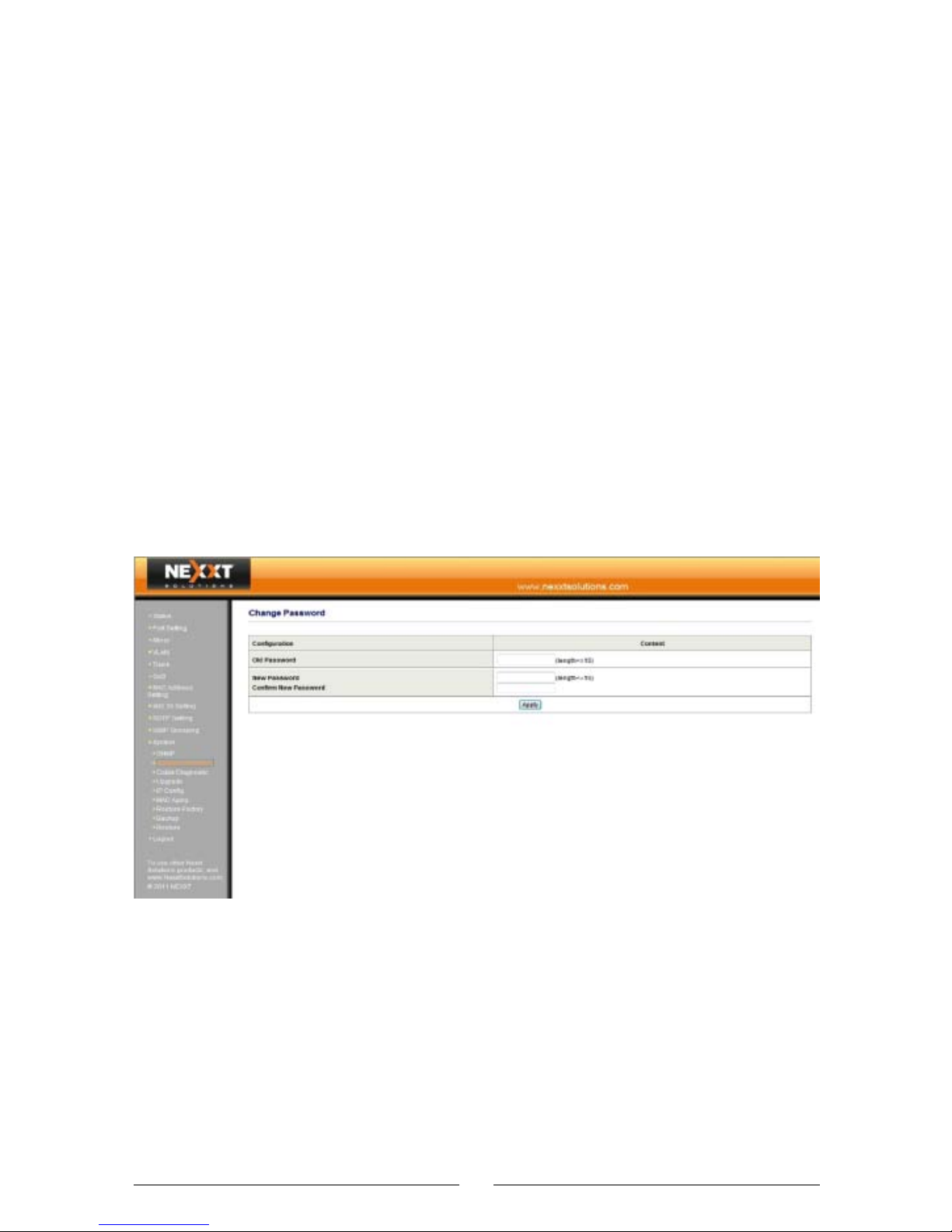
3.12.2 Change Password
Change password window: Modifies the password for
the login.
Old Password: input default password (admin).
New Password: input a new password.
Confirm New Password: input the new password again.
Caution:
A password length cannot exceed 15 characters.
41
•
•
•
•
•
•
Page 43
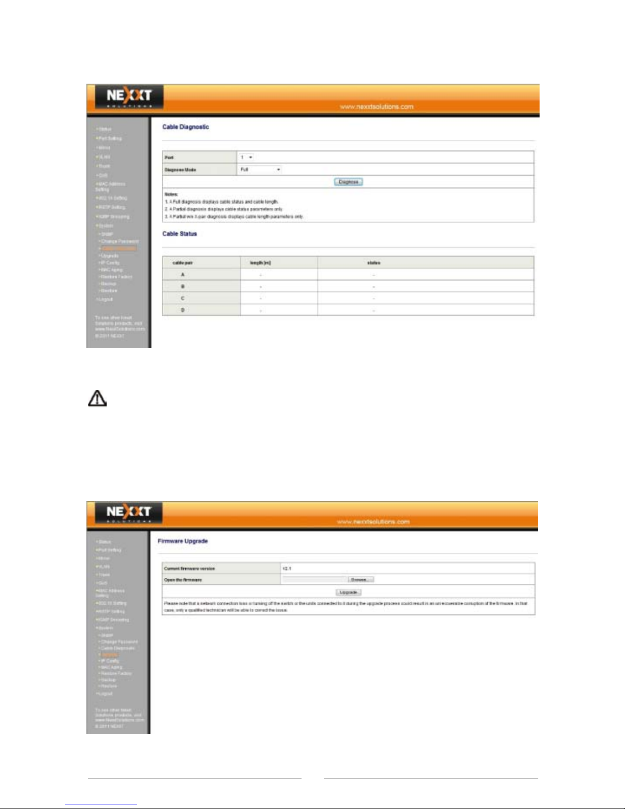
3.12.3 Cable Diagnostic
Cable diagnostic window: Displays the status and length
of the cable selected.
Caution: Since cable noise may vary, the length should
be used only as reference, not as an accurate value for
calculating the interference level.
3.12.4 Upgrade
42
Page 44

Please visit our website to obtain an upgrade package
and detailed upgrade guide. Be cautious during the
upgrade. It is recommended to interrupt all network
connections except the network connection of the
computer used for the upgrade. Do not power off the
system during the upgrade, to avoid computer failure or
other problems.
Firmware upgrade:
1. Log in to our website
http://www.nexxtsolutions.com/dpg/ntDownloads.aspx
and download the software of a higher version.
2. Click “Browse” to locate the upgrade program.
3. Click “Upgrade” to upgrade the software.
Do not power off the switch to avoid damaging the
firmware.
43
Page 45
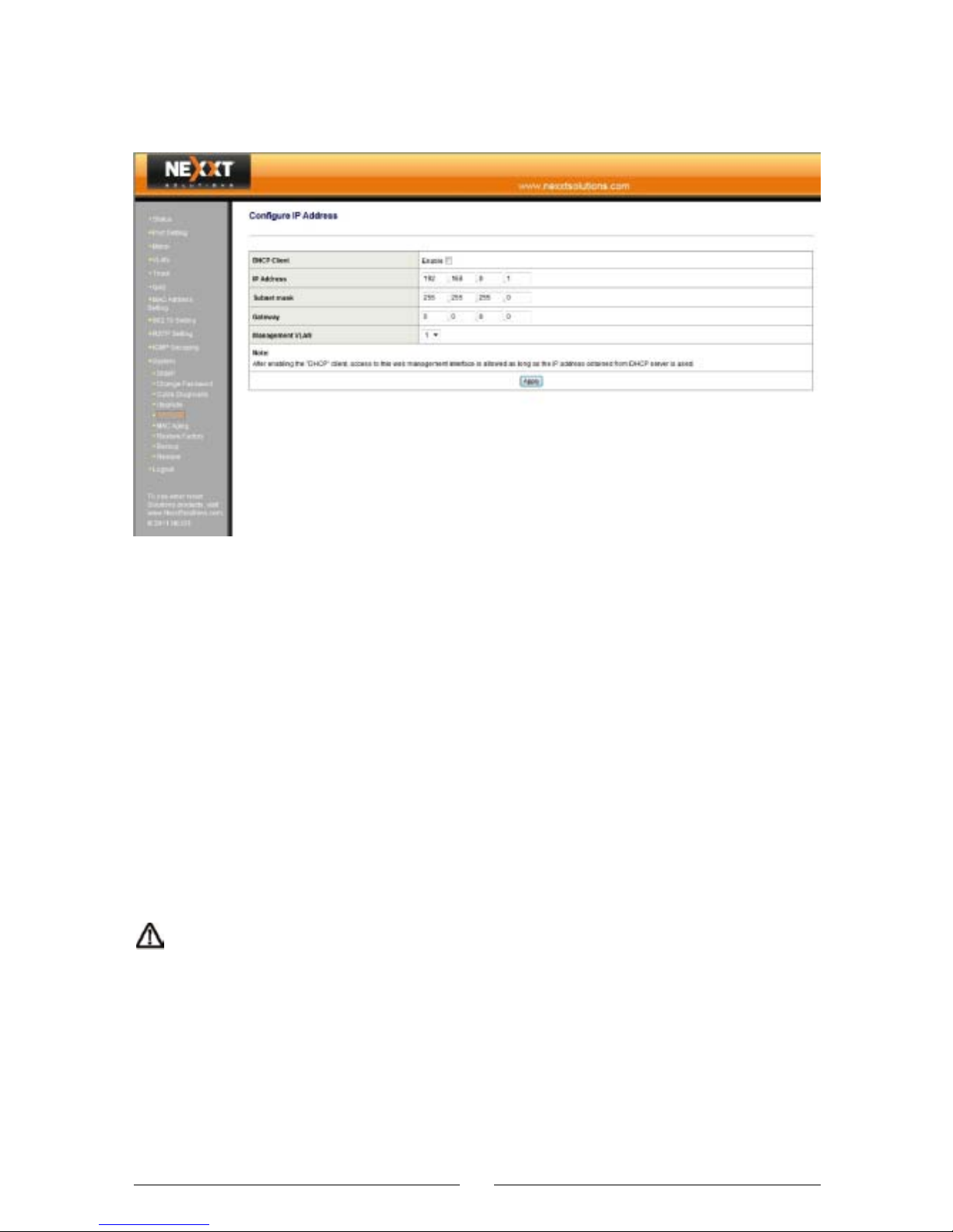
3.12.5 IP Configuration
IP Address: Sets the switch IP address, subnet mask
and default gateway.
DHCP Client: Enables or disables the DHCP client.
IP Address: Changes the switch login IP address (default
is 192.168.0.1).
Subnet mask: Changes the subnet mask of the switch
(default is 255.255.255.0).
Gateway: Changes the gateway of the switch (the default
is 0.0.0.0).
Management VLAN: Selects the VLAN where the
management computer is located.
Caution: After enabling the DHCP client, you need to
check the IP address obtained from the DHCP server and
then connect with the switch again. It is not recommended to use this function, unless you are positive about the
IP address allocated by the DHCP server.
44
•
•
•
•
•
Page 46
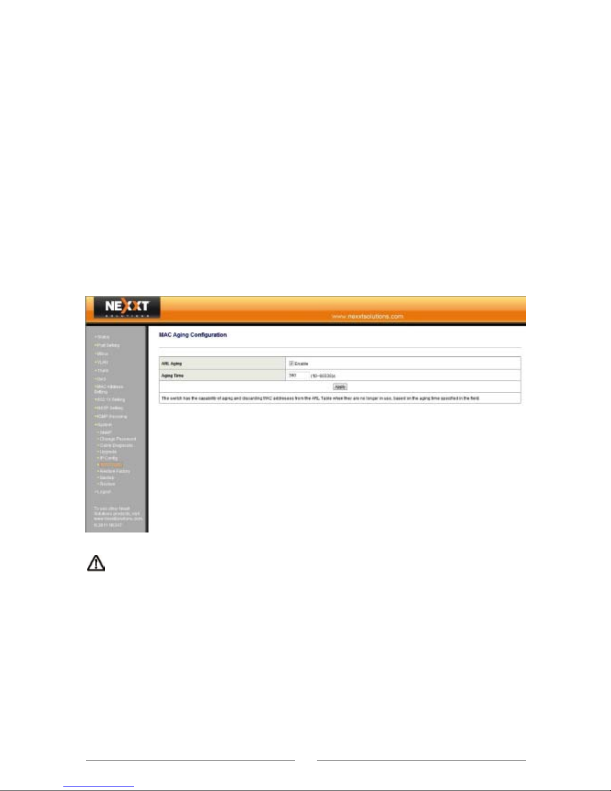
3.12.6 MAC Aging
The default MAC address aging time is 300s. The set
value should be within 10s ~ 65535s to avoid system
errors. If the “ARL Aging” field is not checked, the MAC
address will not be aged.
ARL Aging Configuration:
ARL Aging: Check this option to enable aging.
Aging Time: Defines the MAC address aging time (the
default is 300 seconds).
Caution. If the MAC address aging is disabled, the
switch will stop to renew the new MAC addresses.
Changing the MAC address to static MAC, the MAC
address will not be aged.
45
•
•
Page 47
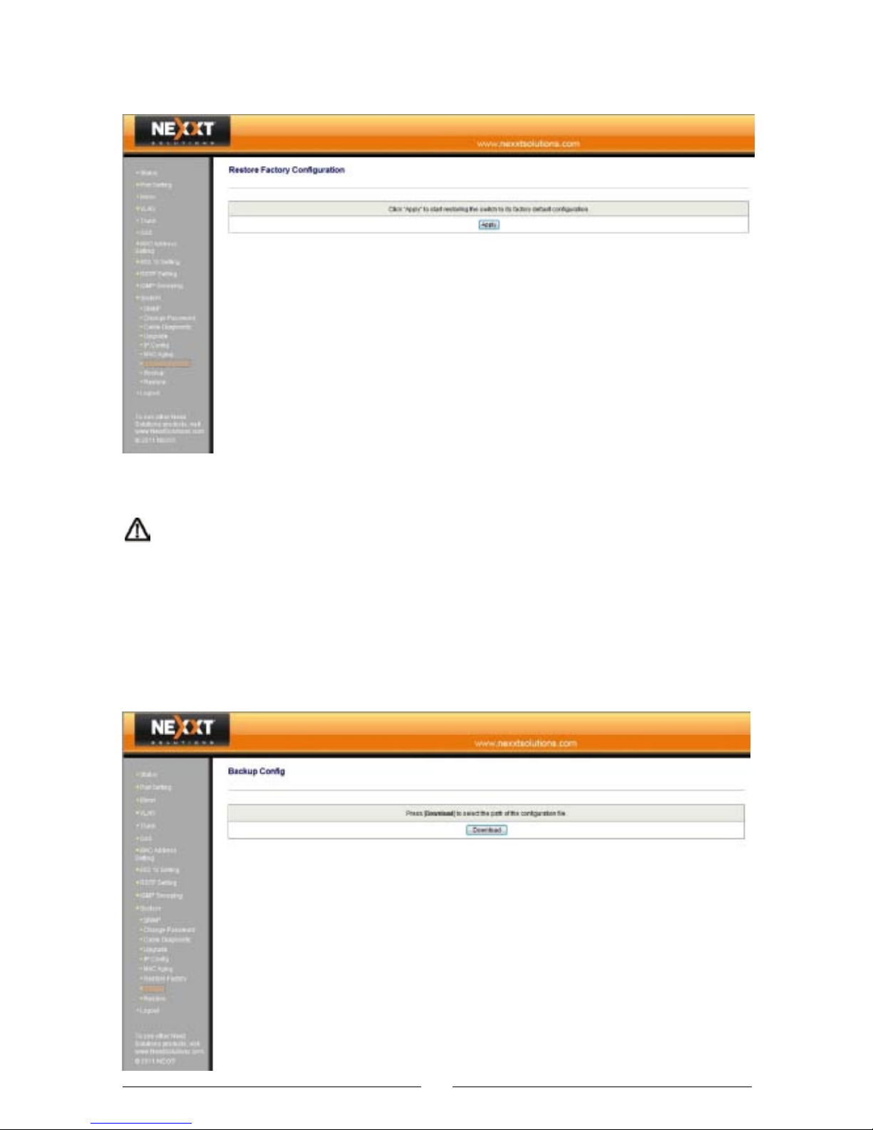
3.12.7 Restore Factory Configuration
Restore Factory Configuration: Click “Apply” to start
restoring the switch to its factory default configuration.
Caution: Log into the switch again after the restoration procedure is finished. If you change the default IP
address before restoring the system, use the default IP
address to re-login (IP address:192.168.0.1, default
username: admin, default password: admin).
3.12.8 Backup
46
Page 48
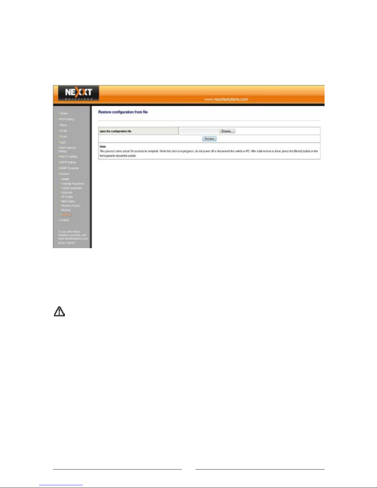
Backup Config: Backs up the current switch configuration. Click “Download” and select the path.
3.12.9 Restore
Restore configuration from file: Restores the backup
switch configuration. Click “Browse” and select the
backup file, then click “Restore”.
:This procedure takes about 30 seconds; do not
power off or disconnect the switch or PC in the middle of
the process. Once restoration is complete, reboot the
switch.
3.12.10 Logout
Logs out from the setting window and leaves the system
at a secure level.
47
Page 49

Appendix 1 Common Commands
48
Common
Commands
cmd
ipconfig
netstat
tracert
net stop
net send
ping
Description
logs into the Windows command mode (available for
Windows2000 or higher version of this Operation
System)
Displays the IP address, such as ipconfig /all
Stops Windows NT network service; e.g.
“net stop dns cache”
Sends messages to another network customer,
computer or communication name. You must run
the messenger service if you want to receive data
messages
Displays detailed information about the current
running network such as network connectivity, the
router table, and network port information. It can
count the quantity of the running network.
Tracert command displays the directory passed
when the packet arrives to its destination; it also
displays the time of arrival to each node. It is similar
to a “ping”, but it can get much more detailed
information than a “ping”. Displays all the passed
directories, node IPs and time spent.
One of the most useful commands in the TCP/IP
protocol: it sends a packet to destination Host and
requires the target host to reply when the packet is
received. In this way, it is possible to evaluate the
network reply time, the connectivity of the original
Host, and the target Host.
Page 50
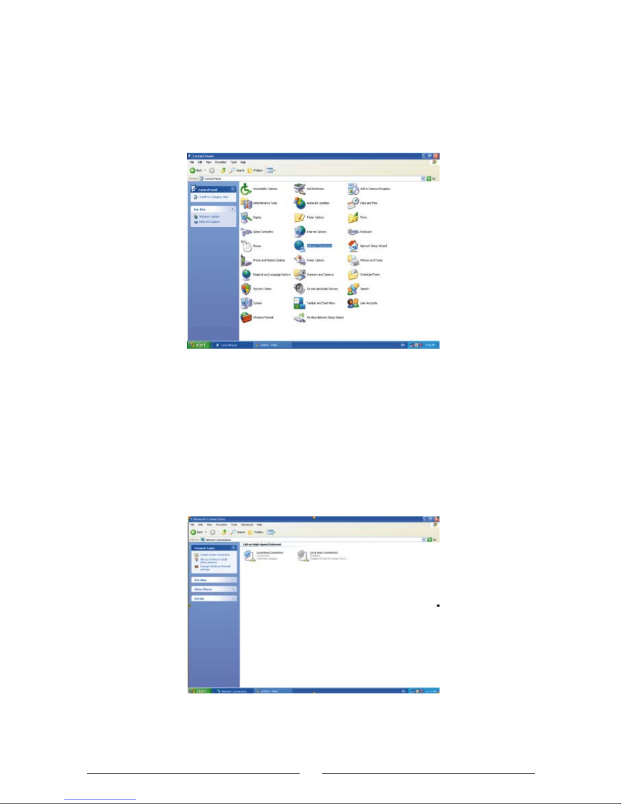
Appendix 2 TCP/IP Example of Address
Setting with Windows XP
Open the “Control Panel”
Figure 1
Click on “Network Connection” to display the “Network
Connections” window (see Figure 2).
Figure 2
49
Page 51
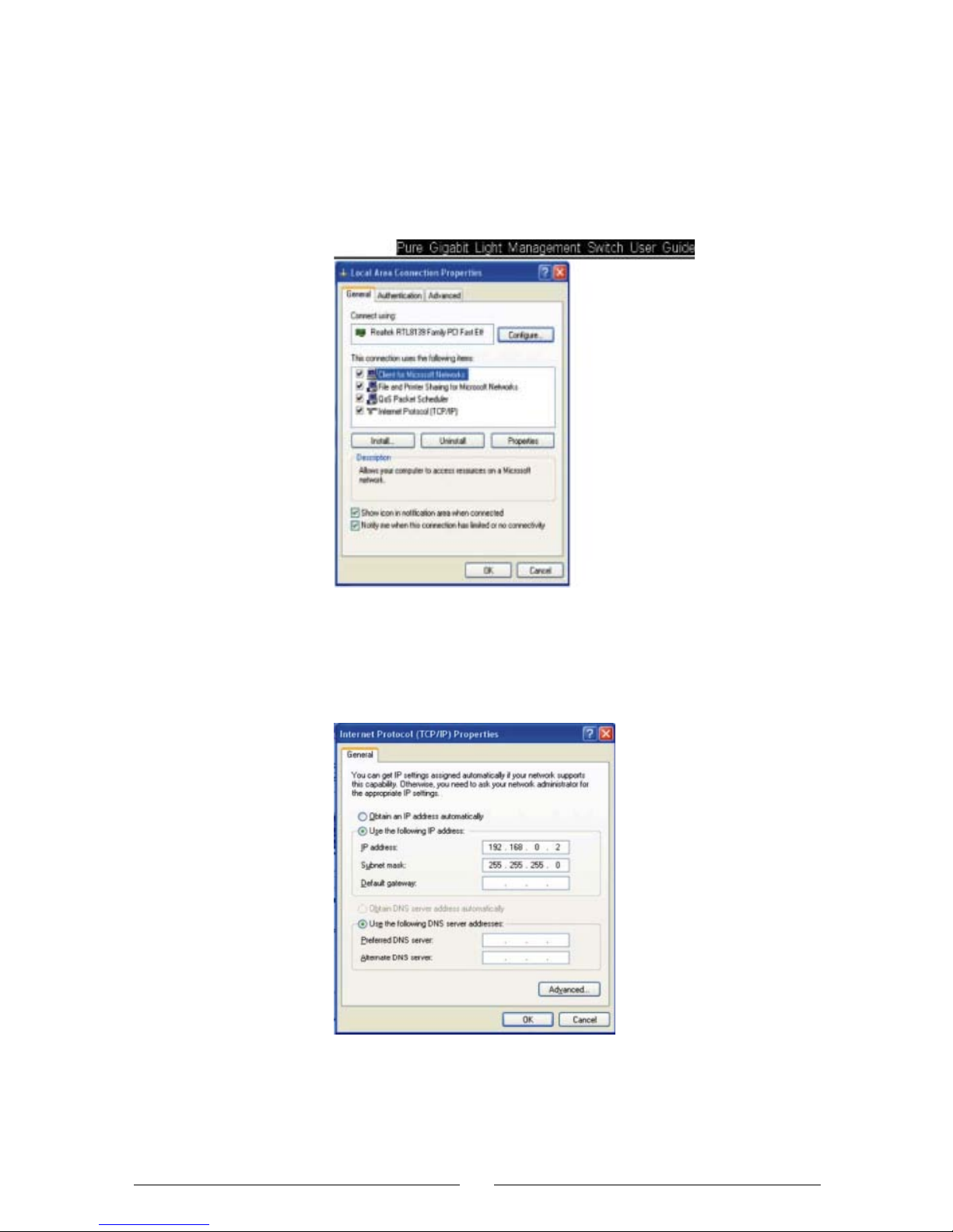
Choose “Local Area Connection”, click the right button of
the mouse to choose “Properties” and activate the “Local
Area Connection Properties” window. Next, choose the
“Internet Protocol (TCP/IP)” item in the “This connection
uses the following items” menu, and click on “Properties”.
Figure 3
Choose “Use the following IP address”, fill in the IP
address as: 192.168.0.xxx. (xxx is the integer between
2~254), subnet mask is: 255.255.255.0.
Figure 4
Click “OK” to return to the “Local Area Connection
Properties” dialog box.
Click “OK” to exit the setting window.
50
Page 52

Appendix 3 Online Technical Support
Should you have any problem during installation, please
visit
http://www.nexxtsolutions.com/dpg/ntContact.aspx.
You may also write to us directly at:
[email protected], for general questions or
support or at [email protected], for
technical support issues and installation help.
51
Page 53

FCC Statement
This equipment has been tested and found to comply with
the limits for a Class B digital device, pursuant to part 15
of the FCC Rules. These limits are designed to provide
reasonable protection against harmful interference in a
residential installation. This equipment generates, uses,
and can radiate radio frequency energy and, if not
installed and used in accordance with the instructions,
may cause harmful interference to radio communications. However, there is no guarantee that interference
will not occur in a particular installation. If this equipment
does cause harmful interference to radio or television
reception, which can be determined by turning the
equipment off and on, the user is encouraged to try to
correct the interference by one or more of the following
measures:
- Reorient or relocate the receiving antenna.
- Increase the separation between the equipment and
receiver.
- Connect the equipment into an outlet on a circuit
different from that to which the receiver is connected.
- Consult the dealer or an experienced radio/TV
technician for help.
 Loading...