

Page 1
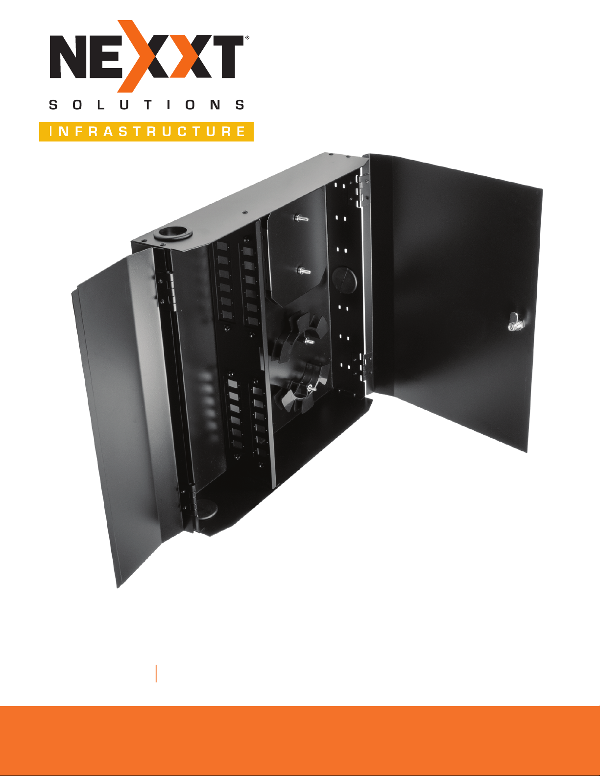
Fiber Distribution Box
24 PORTS UNLOADED WALL MOUNT ENCLOSURE
Model: PCRFIWMUN24BK
Professional Series
Page 2
1. Product overview
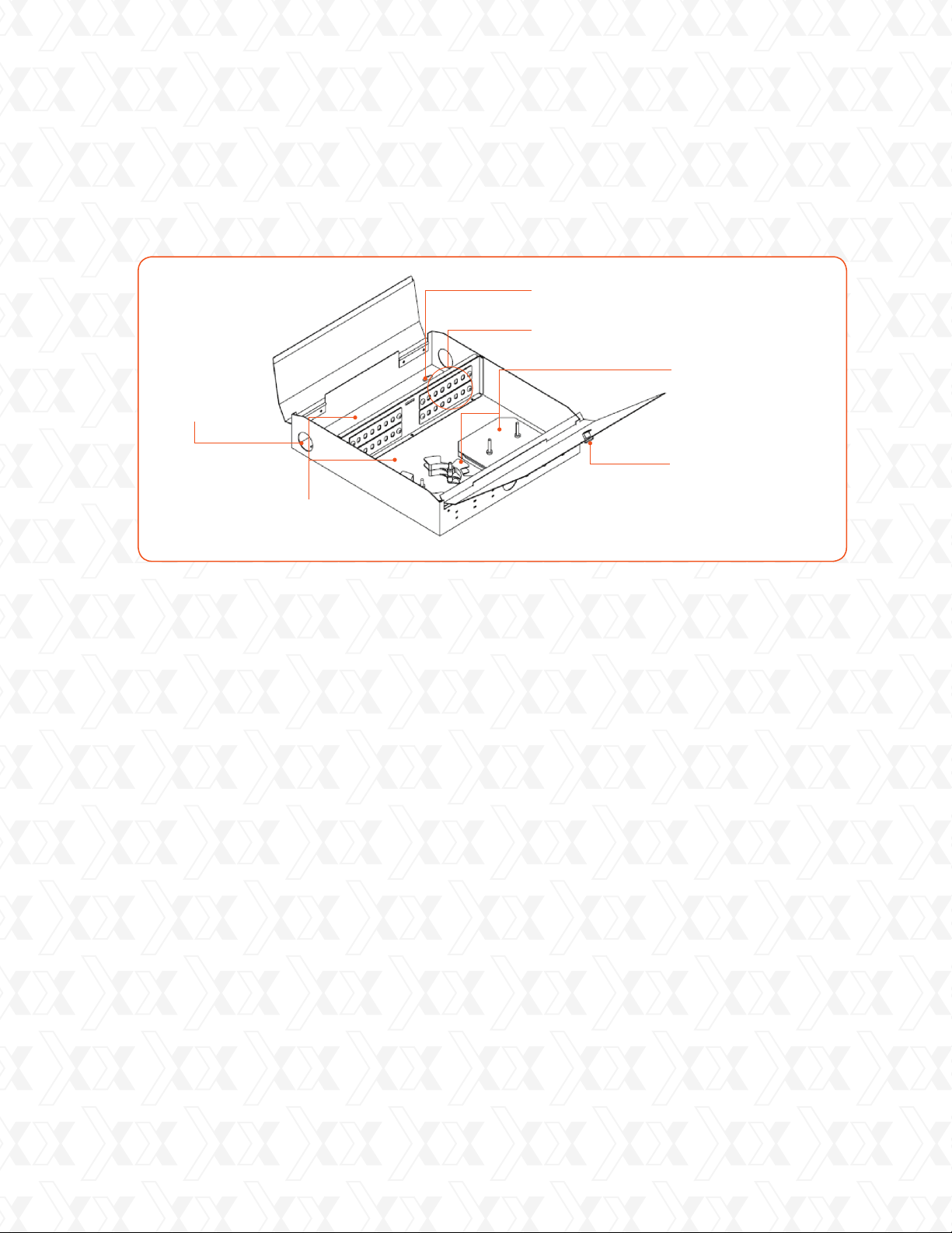
The distribution box is sealed
with grommets for cable
entrance holes to keep out
insects and prevent dust from
setting inside.
The distribution box consists of
two separate compartments.
One for the patch cord and another
one for pigtail splices.
Nexxt Solutions - User guide
Use the appropriate tool to
secure the unit with the supplied
5/32-1 ¼ - inch screws
The adaptor panels are mounted
on the compartment plate of the box.
Each adaptor panel has six outlets.
(Adaptor panel types –SC and LC)
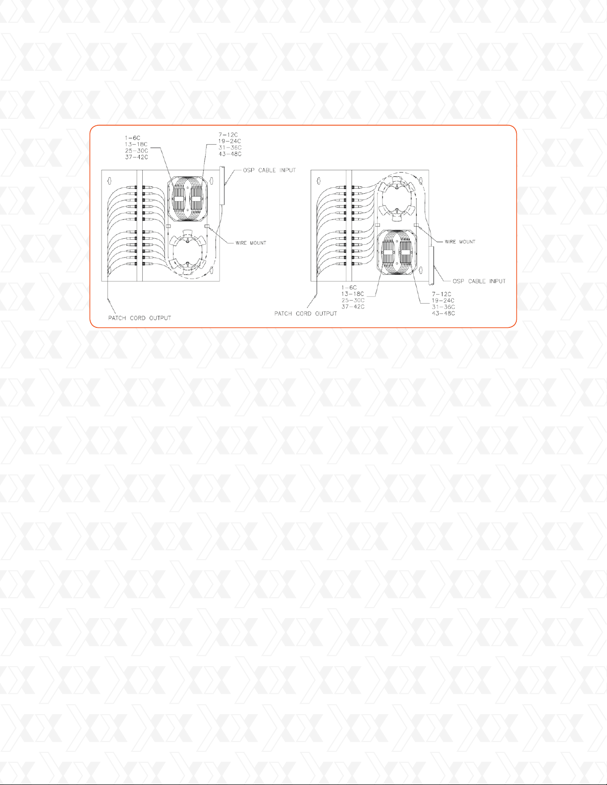
The enclosure is designed for splice tray
and spool cable routing interchangeably
to accommodate outside plant cable
entry in the same compartment from
the top right or bottom right, as shown
in Fig. 2 and 3, respectively.
The two doors are secured
with one cam lock
Fig. 1
The distribution box provides storage space for fiber splices and excess lengths of pigtail
1-1
and patch cords.
The distribution box is made of heavy gauge SPCC, featuring a compact and rugged
1-2
construction. The epoxy-baked paint finish is corrosion-resistant to saline environments.
The distribution box has two splice trays. Each splice tray secures and accommodates up
1-3
to 12 splices provided that they have a minimum bending radius of 37.5mm from
the fibers to be incorporated, which also ensures minimal cable slack by providing
storage space for excess lengths of patch cords.
The distribution box has cable routing spools which provide storage for excess length
1-4
of cables.
2
Page 3
Nexxt Solutions - User guide
Fig. 2 Fig. 3
2. Installation
Place the twist ties at the proper location compartment to maintain a minimum fiber
2-1
routing radius of 37.5mm.
Due to the interchangeability of the mounting location for splice trays and spool cable
2-2
routing, if the outside plant cable enters the box from the top, the installation steps
of fig. 2 should be followed. But if the outside plant cable is routed from the bottom of
the box, then the installation steps shown in fig. 3 should apply.
Note: The outside plant cable can also enter the distribution box from the top left or
bottom left by turning the unit upside down, if needed.
2-3
Unsheathing the optic fiber cable
Cut the outside jacket of the fiber cable to a length of approximately 600mm.
Use the cable ties provided to fasten the optic fiber, as shown in fig 2 and 3.
2-4
Splicing
Pigtail fibers must be spliced to the optic fiber of the outside plant cable. When splicing,
the following steps shall be taken into consideration:
Determine and prepare the appropriate length of the fibers to be spliced according
•
to the splicing machine recommendations.
The bare fibers to be spliced from pigtails and outside plant cable must be equal to
•
the lay length on the splice holder. The splice holder inside the splice tray can be easily
removed for splicing, if required.
Insert heat-shrink splice protector sleeve to either end of the two optic fibers to be
•
spliced before beginning splicing the cables.
3
Page 4

Nexxt Solutions - Installation guide
The splice trays are used to hold and protect the finished splices. After the process of
2-5
splicing is completed, insert the protector sleeve in the splice holder, then the excess
length of the pigtail can be coiled around the cable routing spool.
3. Pigtail and outgoing cable routing
Pigtail cable routing
3-1
When pigtail and outside plant cable have been properly spliced, the pigtails shall be
routed as shown in fig.2 and 3.
Outgoing cable routing
3-2
When patch cords are connected using an adaptor, the excess patch cord length can be
routed and secured using the twist ties.
4. Connecting pigtails and patch cords
Remove the adaptor dust caps and mate the pigtail and patch cord using
4.1
the adaptors.
It is required to number the adaptors.
4.2
Inspect the fiber splice joints, pigtail routing prior to locking the doors.
4.3
5. The pack includes:
Splice protector sleeve
4-inch wire tie
6-inch cable tie
Self-adhesive twist tie
Warning and connectivity label
Screw 5/32 – 1 ¼
Installation Instructions
6. Unit size
24-port enclosure
27
pcs
10
pcs
6
pcs
6
pcs
1
pc
4
pcs
1
pc
350x370x81.5mm
4
 Loading...