

Page 1
WAN 3 2 1
PWR WPS/RST
B.Ethernet Access
Modem
Internet
Internet
Ethernet Cable
A.Telephone Line/FTTH
(Fiber To The Home)/
Cable Acces
O
The defaul name is
Nexxt XXXXXX
The is no defaul WIFI password.
*Images herein are for references only. The actual product may differ.
Ethernet Cable
WAN
Quick installation guide
1 2 3
1
Preliminary steps
Router configuration
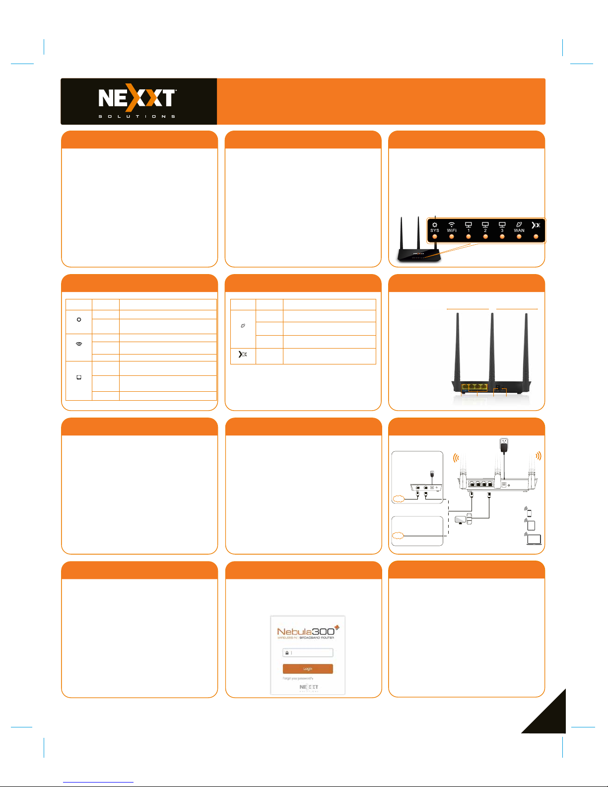
Product layout
This advanced network device works as a router,
wireless AP, and universal repeater. Before setting
up the router, you must verify that you have
high-speed internet access available. The most
widely used connection nowadays is broadband
DSL or cable. The description used in this guide is
based on that type of connection.
1. Antennas: Three high-gain 5dBi omnidirectional
antennas.
2. WAN port: This RJ45 port is where you will connect the
DSL/cable modem, or ethernet line.
3. LAN ports (1/2/3): Connect 10/100Mbps ethernet
devices such as computers, switches, and hubs to any of
these RJ45 ports.
4. Power: Connect the supplied power adapter to this jack.
5.WPS/Reset:
1. Power off your PC, cable/DSL modem and the router.
2. Find the optimum location for the router. The best place is
usually at the center or your wireless network with the
antennas in the upright position.
3. Connect one end of the supplied power adapter to the AC
input jack located on the rear panel of the router, before
plugging the other end to a standard electrical wall outlet.
4. Connect your network devices to the LAN ports of the router.
Then using an ethernet cable, connect your modem to the
WAN port in order to gain internet access.
5. Finally, power on the router, your PC and modem.
Thank you for purchasing the new Nebula 300+
wireless-N router from Nexxt Solutions™. If any of
the following items are mismatched, missing or
damaged, please contact the merchant from
whom you purchased the unit for immediate
replacement.
• Wireless-N router
• 100/240V power adapter
• Network cable
• Quick installation guide
4 5 6
7 8
10 11 12
9
1.Log into the router by accessing the web base
utility. To do so, in the browser’s address field enter
the default address http://192.168.0.1 or
nexxtwifi.com.
Note: To access the router wirelessly, look for the
SSID, Nexxt_XXXXXX (whereby X represents the
last 6 numbers of the MAC address).
2. In this stage, the wireless router web interface will
come up. The system will then prompt you to enter the
default password. Type admin and click Login to
continue.
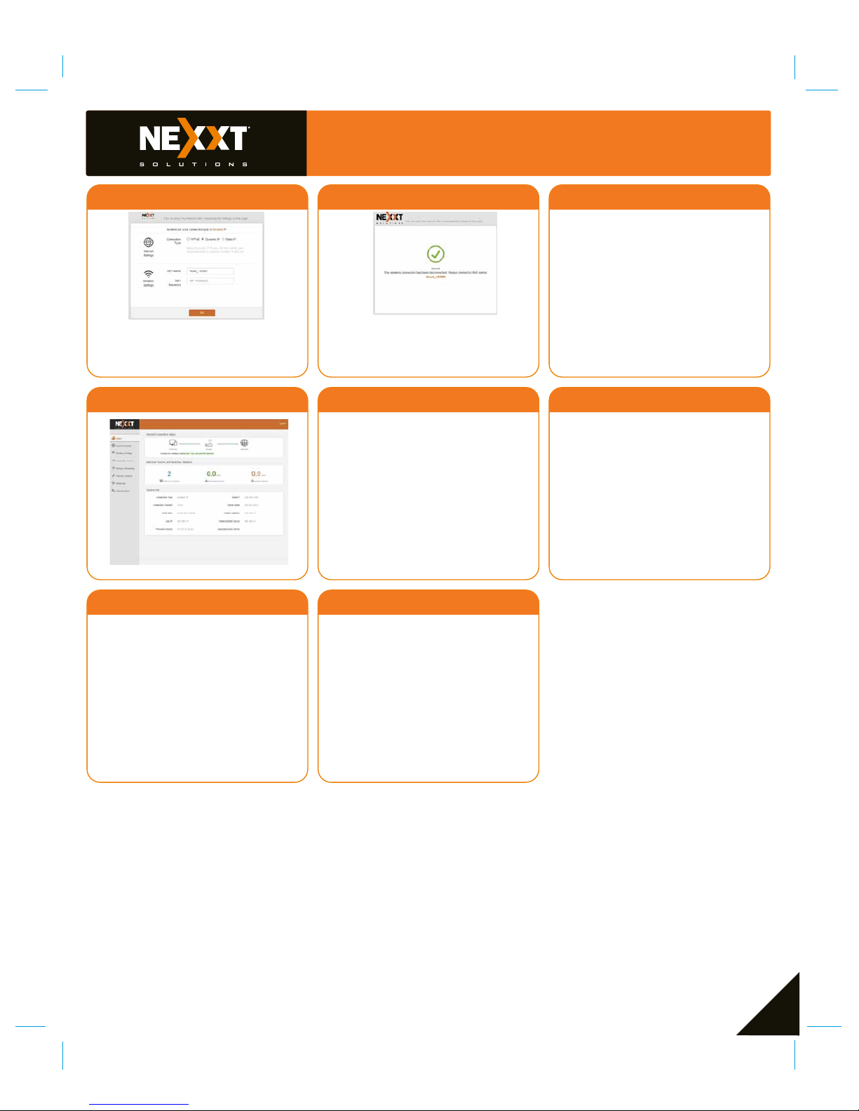
3. Next, the Basic settings page will be displayed. In this
window, you will be prompted to select the Internet
Connection Type, which will depend on the type of
connection offered by your existing Internet Service
Provider (ISP): PPPoE, for dial-up or DHCP for other
broadband connections. You can also set it up to use
a Static IP configuration. By default, the router will
auto-detect the connection type and set it to the
corresponding configuration. You can also setup the
wireless password and SSID under the Wireless
Settings area (by default, this is blank). For security
purposes, we recommend using a security key at this
stage. It must contain at least 8 characters. Click
OK to complete the initial set up of the router.
Front panel
Back panel
The rear panel
provides the physical
connectors for power
and the client network
devices.
2 3 4 5
Hardware installation
N
1
・ Press this button for about one second to enable WPS
encryption. Within two seconds, enable the WPS feature
on the client device to establish a connection.
・ Press this button for about eight seconds to restore the
device to its factory default settings. All LED indicators will
light up.
LED indicators on the front panel provide information
about network activity, the connection and link status of
the ports in real time. They also facilitate activity monitoring and troubleshooting the performance of the device.
LED
indicator
Blinking The system is working properly
No link is detected on that port
Off
Blinking
Off
Solid
Solid
Blinking
Off
No power is being supplied to the router or
the device is malfunctioning
The Wi-Fi radio is enabled
The Wi-Fi radio is disabled
The link between the router and a device
is established through that port
The device is actively sending or
transmitting data over that port
The device is actively sending or
transmitting data using wireless link
Status Description
SYS
WiFi
LAN 1~3
LED
indicator
Solid
Blinking
The link between the router and a device
is established through that port
Off
No ethernet cable is connected to that
port
The device is actively sending or
transmitting packets over that port
There is no function or indication
associated with this LED
Status Description
WAN
N
N
Page 2
Quick installation guide
13 14
2
16 17 18
15
3
2019
This device complies with Part 15 of the FCC Rules.
Operation is subject to the following two conditions: (1)
This device may not cause harmful interference, and (2)
this device must accept any interference received,
including interference that may cause undesired operation.
This equipment has been tested and found to comply with
the limits for a Class B digital device, pursuant to Part 15
of the FCC Rules. These limits are designed to provide
reasonable protection against harmful interference in a
residential installation. This equipment generates, uses
and can radiate radio frequency energy and, if not
installed and used in accordance with the instructions,
may cause harmful interference to radio communications.
However, there is no guarantee that interference will not
occur in a particular installation. If this equipment does
cause harmful interference to radio or television reception, which can be determined by turning the equipment
off and on, the user is encouraged to try to correct the
interference by one of the following:
FCC statement
Reorient or relocate the receiving antenna.
Increase the separation between the equipment and
receiver.
Connect the equipment into an outlet on a circuit
different from that to which the receiver is connected.
Consult the dealer or an experienced radio/TV
technician for help.
•
•
•
•
Any changes or modifications not expressly approved by
the party responsible for compliance could void the user's
authority to operate the equipment.
This transmitter must not be co-located or operated in
conjunction with any other antenna or transmitter.
The manufacturer is not responsible for any radio or TV
interference caused by unauthorized modifications to this
equipment.
Caution!
This equipment complies with FCC radiation exposure
limits set forth for an uncontrolled environment. This
equipment should be installed and operated with
minimum distance 20cm between the radiator & your
body
Radiation exposure statement
FCC ID: X4YNBL300P
4. Once complete, you will get a successful setup
message. If the SSID and password were changed in
the previous step, you will need to access the router
using the newly assigned parameters.
5. If the computer you used to set up the router can
access the internet, it means that you have successfully
configured the device, and that other computers in the
LAN should also be able to do the same. If they don’t,
verify that the Internet Protocol is set to obtain the IP
and DNS settings automatically.
To do so, right click Network > Properties > Change
adapter settings, followed by Local area connections >
Properties. Next, double click on Internet protocol
version (4 or 6 based on your connection) and finish by
selecting Obtain DNS server and IP address automatically. Please note that the path indicated above relates
to Windows 7. Other operating systems may differ, so
make sure to follow the instructions of the operating
system you are using. If you later wish to customize your
wireless router’s configurations, login to the router and
click on the corresponding menu options you desire to
customize.
 Loading...