


PSH150 user manual rev4
Page 1/15
PSH150
10kV Isolation Programmable Power
Supply
User Manual
POWERMASTER

PSH150 user manual rev4
Page 2/15
DISCLAIMER
NEXTYS
reserves the right to make changes without further notice to any products herein.
NEXTYS
makes no warranty, representation or guarantee regarding the suitability of its products for any
particular purpose, nor does
NEXTYS
assume any liability arising out of the application or use of any
product, and specifically disclaims any and all liability, including without limitation consequential or
incidental damages. “Typical" parameters which may be provided in
NEXTYS
data sheets and/or
specifications can and do vary in different applications and actual performance may vary overtime. All
operating parameters, including “Typicals", must be validated for each customer application by
customer's technical experts.
NEXTYS
does not convey any license under its patent rights nor the
rights of others.
NEXTYS
products are not designed, intended, or authorized for use as components in
systems intended for surgical implant into the body, or other applications intended to support or
sustain life, or for any other application in which the failure of the
NEXTYS
product could create a
situation where personal injury or death may occur. Should Buyer purchase or use
NEXTYS
products
for any such unintended or unauthorized application, Buyer shall indemnity and hold
NEXTYS
and its
officers, employees, subsidiaries, affiliates, and distributors harmless against all claims, costs,
damages, and expenses, and reasonable attorney fees arising out of, directly or indirectly, any claim
of personal injury or death associated with such unintended or unauthorized use, even if such claim
alleges that
NEXTYS
was negligent regarding the design or manufacture of the part.
The Customer should ensure that it has the most up to date version of the document by contacting its
local
NEXTYS
office. This document supersedes any earlier documentation relating to the products
referred to herein. The information contained in this document is current at the date of publication. It
may subsequently be updated, revised or withdrawn.
The Customer should ensure that
NEXTYS
product uses the most up to date Software and Firmware
provided on
NEXTYS
website to ensure reliable operation of the system.
All Trade Marks recognized. Specifications and information herein are Subject to change without
notice.

PSH150 user manual rev4
Page 3/15
TABLE OF CONTENTS
1 Product description ........................................................................................................................ 4
2 Features and benefits .................................................................................................................... 5
3 Functional description .................................................................................................................... 6
3.1 Main DC output ..................................................................................................................... 7
3.2 Auxiliary 12V output ............................................................................................................... 8
3.3 INHIBIT input ......................................................................................................................... 8
3.4 Display interface .................................................................................................................... 8
3.4.1 Normal operation ............................................................................................................. 8
3.4.2 Menu navigation .............................................................................................................. 9
3.4.3 Alarm codes ................................................................................................................... 10
3.5 Parallel connection .............................................................................................................. 10
3.6 Modbus Interface ................................................................................................................. 11
4 Installation ................................................................................................................................... 12

PSH150 user manual rev4
Page 4/15
1 Product description
Use latest device Documentation, Software and Firmware to ensure reliable operation of
the system (downloadable from www.nextys.com).
PSH150 is an advanced DIN rail 1-phase input, 150W SMPS (Switched Mode Power Supply) with a
distinctive feature: 10kV isolation between primary and secondary.
This allows it to be used in energy management, telecom, renewable energy and other demanding
applications.
Figure 1: Front panel view
1. AC input: 2 poles are provided for input connection. This must be connected to the AC or
DC line source. Voltage range is 90…277Vac or 110…400Vdc.
2. Modbus over USB: Used to connect a device running POWERMASTER or custom
application. Firmware update is also possible.
3. Modbus over RS-485: Used to connect a device running POWERMASTER or custom
application. Firmware update is also possible.
4. INHIBIT input: A voltage between 5Vdc and 30Vdc applied to this input activates the
inhibit function (§3.3).
5. Auxiliary 12Vdc output: This output provides a regulated 12Vdc output with 100mA
maximum output current. This output is short circuit protected (§3.2).
6. DC-OK dry contact: normally open and normally closed relay contacts are available; the
relay closes when the output voltage is >90% of the programmed output voltage value.
7. DC Output: 4 poles are provided for output connection; it must be connected to the load.
The output voltage is adjustable between 5…55Vdc. (§3.1)
8. Control keys: 3 push buttons are provided to navigate through menus and to select
various functions.
9. Display: 3-digits LED display providing information about the device status (§3.4).
10. Units LEDs: 2 green LEDs are used to indicate the actual measurement indicated on the
display (§3.4.1).
11. Alarm LED: blinking when there is an alarm; the relevant alarm code is indicated on the
display (§3.4.3).

PSH150 user manual rev4
Page 5/15
2 Features and benefits
Class II wiring (PE connection not required)
10kVac primary to secondary isolation (suitable for energy management applications)
Wide output voltage range 5…55Vdc, user settable
Auxiliary 12V/100mA power supply
High efficiency and compact size
Remote ON/OFF or other remote control functions possible through INHIBIT input
Modbus over RS-485 or USB interfaces for control and monitoring
Multiple protections
Can be paralleled for power or redundancy (integrated ORing circuitry)
Up to 50°C operating temperature with no derating
Wall mount fixing possible
Suitable for POWERMASTER software (available for Windows and Android)
Embedded user interface:
3 keys and 3 digits 7-segments LED display
Allows online device configuration
Displays the PSH150 status and alarms
Free PC and Android application POWERMASTER used for:
Connection through Modbus
Remote monitoring and configuration
Firmware upgrade
Same functionalities of the embedded used interface with the ease of the PC benefits

PSH150 user manual rev4
Page 6/15
3 Functional description
PSH150 includes a 1 phase SMPS module with PFC and class II wiring. A converter located on the
secondary side allows the supply of a programmable voltage (5 to 55V), with user settable current
limitation. The output is provided with an active ORing circuit that allows the parallel connection for
redundancy of several units without the need of an external redundancy module.
An auxiliary power supply of 12V/100mA is available.
An external INHIBIT signal can be applied for controlling the output status.
A multifunctional display shows the output parameters and 3 keys can be used for programming the
unit. A dry contact (relay) is related to “DC-OK” status.
RS485 and USB ports are available for remote monitoring and setup.
Power path
Monitoring and control
EMI
f ilter
PFC
Input
Isolation
10kV
DC
DC
DC
DC
I
U
Output voltage
and current
measurement
Digital
fuse
U
Voltage
measurement
Output
Aux
supply
uController
Modbus/RTU
USB
RS485
I/O
Relay
Inhibit
HMI
Digital control
DC/DC
converter
Figure 2: PSH150 simplified block diagram

PSH150 user manual rev4
Page 7/15
3.1 Main DC output
PSH150 provides a DC output programmable from 5Vdc to 55Vdc with up to 12A output current and a
maximum output power of 150W. The maximum output current varies according to the programmed
output voltage and to the ambient temperature; in Figure 3 and Figure 4 the current and power
derating curves are reported.
Current Derating Curve
0
2
4
6
8
10
12
14
-40 -30 -20 -10 0 10 20 30 40 50 60 70 80
Temperature [°C]
Current [A]
5V 12V 24V 48V
Figure 3: PSH150 current derating curves
Power Derating Curve
0
40
80
120
160
-40 -30 -20 -10 0 10 20 30 40 50 60 70 80
Tem perature [°C]
Power [W]
5V 12V 24V and 48V
Figure 4: PSH150 power derating curves
The output is short circuit protected; in case of an output short circuit the output is switched off and an
hiccup cycle is started. A “short circuit” alarm code is reported on the display (§3.4.3).

PSH150 user manual rev4
Page 8/15
3.2 Auxiliary 12V output
PSH150 is provided with an auxiliary regulated 12V output with up to 100mA current capacity. This
output is short circuit protected. The auxiliary output shares the same ground (negative terminal) with
the main DC output.
3.3 INHIBIT input
An opto-isolated input allows switching off the main DC output. The polarity of the input can be
defined using the “inhibit polarity” (POL) field (§3.4.2). The controlling signal must have a voltage
between 5Vdc and 30Vdc. The auxiliary 12V output is always active and can not been switched off.
3.4 Display interface
The PSH150 is provided with a 3-digits 7-segments LED display used to indicate the status and to
navigate through the configuration menus. During normal operation, the output parameters are
reported (§3.4.1). Alarms and error codes are also reported on the display (§3.4.3)
3.4.1 Normal operation
During normal operation the output voltage, current and power are reported on the display. 2 green
LEDs indicate which measurement is currently shown. Every parameter is visible for 3 seconds, then
the next measurement is shown.
V
A
!
W
Output voltage measurement:
The display is indicating 24.0V. Note that the “V”
green LED is on, indicating voltage
measurement.
V
A
!
W
Output current measurement:
The display is indicating 6.0A. Note that the “A”
green LED is on, indicating current
measurement.
V
A
!
W
Output power measurement:
The display is indicating 144W. Note that both
the “V” and “A” green LEDs are on, indicating
power measurement.
.

PSH150 user manual rev4
Page 9/15
3.4.2 Menu navigation
The layout of the menu is shown in Figure 5. The various options are selected with the 3 keys.
2s
2s
Set
Set
(Stor e)
Set
5s 5s
Output
Volta ge
(No st ore)
2s
Set
Set
(Stor e)
Set
5s
Output
Volta ge
Output
measures
Output
voltage
Inhibit
polarity
5s
(No st ore)
2s
Set
Set
(Stor e)
Set
5s
Output
Volta ge
Operating
mode
5s
(No st ore)
2s
Set
Set
(Stor e)
Set
5s
Output
Volta ge
Modbus
addess
5s
(No st ore)
2s
Set
Set
(Stor e)
Set
5s
Output
Volta ge
Modbus
baudrate
5s
(No st ore)
2s
Set
Set
(Stor e)
Set
5s
Output
Volta ge
Modbus
stop bits
5s
2s
Set
Set
(Stor e)
Set
5s
Output
Volta ge
Modbus
parity
5s
(No st ore)
Allowed values: 5..55V
Default value: 5V
Allowed values: Low (LO), High (Hi)
Default value: High
Allowed values: Single (SI), Parallel (PA)
Default value: Single
Allowed values: 1..247
Default value: 1
Allowed values: 4.8, 9.6, 19.2, 38.4Kb/S
Default value: 38.4
Allowed values: 1, 2
Default value: 1
Allowed values: None (No), Even (Ev), Odd (Od)
Default value: Even
Over temperature
Output short circuit Internal error
u
Figure 5: HMI
PSH150 user manual rev4
Page 10/15
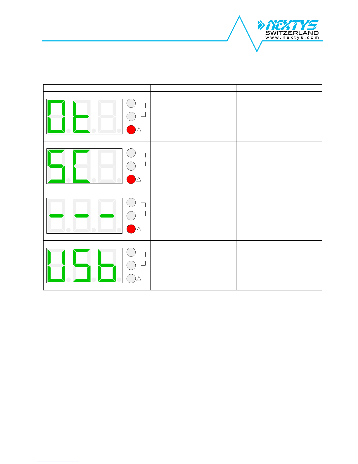
3.4.3 Alarm codes
In case of internal or external faults an error code is reported on the display. When an error code is
reported the “Alarm” red LED blinks at 1Hz rate.
Display code
Description
Behaviour
V
A
!
W
Over-temperature protection
The red LED blinks
The output is switched off
until the internal temperature
decreases to safe values
V
A
!
W
Short circuit protection
The red LED blinks
The output current is limited
at the programmed value for
5 seconds, then the product
switches off for 10 seconds.
The cycle is repeated until
the short circuit is removed
V
A
!
W
Internal error, non
recoverable
The red LED blinks
The output is switched off.
This error is caused by an
unrecoverable internal fault
V
A
!
W
USB power, no mains
available
The product is powered
through USB and the input
mains is not present. The
user can navigate through
the menus. It can be used for
firmware upgrade without the
need of the input mains.
3.5 Parallel connection
Multiple PSH150 can be connected with the output in parallel for power increase and / or redundancy.
In this mode of operation, the field “operating mode” (OP) shall be set to “Parallel” (PA).
The unit integrates an internal ORing circuit allowing paralleling several units for redundancy.
For proper operation the cable length connecting the PSH150 outputs to the load must have the same
length and cross-section. For optimal current sharing it may be necessary to slightly adjust one of the
two devices output voltage until the same current is delivered by the two units. It is recommended to
limit the load power to 80% of the sum of the individual output power of the paralleled units.

PSH150 user manual rev4
Page 11/15
3.6 Modbus Interface
PSH150 supports Modbus RTU over RS-485 line or USB (Virtual com port). The following Modbus
table is implemented:
Name
Address
Hex (dec)
Modbus type
Function
code
Description
Modbus settings (loaded on next startup)
Address
0x1000 (4096)
Hold register
3,4,6,16
Range 1..247
Baudrate
0x1001 (4097)
Hold register
3,4,6,16
1: 4800
2: 9600
3: 19200
4: 38400
Parity
0x1002 (4098)
Hold register
3,4,6,16
1: None
2: Even
3: Odd
Stop bits
0x1003 (4099)
Hold register
3,4,6,16
1: 1 stop bits
2: 2 stop bits
Device settings
Output voltage
0x1010 (4112)
Hold register
3,4,6,16
Inhibit polarity
0x1011 (4113)
Hold register
3,4,6,16
Operating mode
0x1012 (4114)
Hold register
3,4,6,16
Display mode
0x1013 (4115)
Hold register
3,4,6,16
1: Automatic
2: Voltage
3: Current
4: Power
Output enable
0x1014 (4116)
Hold register
3,4,6,16
0: Disabled
1: Enabled
Auxiliary output
enable
0x1015 (4117)
Hold register
3,4,6,16
0: Disabled
1: Enabled
Metering
Output voltage
0x2000 (8192)
Input register
3,4
Measured output voltage
Output current
0x2001 (8193)
Input register
3,4
Measured output current
Output power
0x2002 (8194)
Input register
3,4
Measured output power
Auxiliary voltage
0x2003 (8195)
Input register
3,4
Measured auxiliary voltage
Internal
temperature
0x2004 (8196)
Input register
3,4
Measured internal temperature
State
DC OK
0x4000 (16384)
Discrete input
1,2
Measured output voltage is >90% of the
set point
Output short
circuit
0x4001 (16385)
Discrete input
1,2
A short circuit is present on the output
Auxiliary overload
0x4002 (16386)
Discrete input
1,2
Auxiliary output is overloaded
Inhibit signal
0x4003 (16387)
Discrete input
1,2
Status of the inhibit signal
USB powered
0x4004 (16388)
Discrete input
1,2
Device is powered by USB only
Over temperature
warning
0x4005 (16389)
Discrete input
1,2
Device internal temperature is high
Over temperature
error
0x4006 (16390)
Discrete input
1,2
Device internal temperature is too high,
the output is disabled
Internal error
0x4007 (16391)
Discrete input
1,2
An internal error occurred, the output is
disabled
Output disabled
0x4008 (16392)
Discrete input
1,2
Output is disabled in settings.
Auxiliary output
disabled
0x4009 (16393)
Discrete input
1,2
Auxiliary is disabled in settings.

PSH150 user manual rev4
Page 12/15
4 Installation
READ THIS CAREFULLY BEFORE INSTALLATION!
LEGGERE ATTENTAMENTE PRIMA
DELL’INSTALLAZIONE!
A LIRE ATTENTIVEMENT AVANT L’INSTALLATION!
Before operating, read this document thoroughly and
retain it for future reference.
Non-respect of these instructions may reduce
performances and safety of the devices and cause danger
for people and property.
The products must be installed, operated, serviced and
maintained by qualified personnel in compliance with
applicable standards and regulations.
Don’t open the device, it does not contain replaceable
components, the tripping of the internal fuse (if included) is
caused by an internal failure.
Don’t repair or modify the device, if malfunction or failure
should occur during operation, send unit to the factory for
inspection. No responsibility is assumed by Nextys SA for
any consequences deriving from the use of this material.
Prima dell’installazione, leggere attentamente questo
documento istruzioni e conservarle per future consultazioni.
L’inosservanza delle presenti istruzioni può compromettere le
caratteristiche e la sicurezza dell’apparecchio e causare
pericolo per le persone e le cose.
Il prodotto deve essere installato, utilizzato e riparato da
personale qualificato e nel rispetto delle normative vigenti.
Non aprire il prodotto, esso non contiene componenti
sostituibili, il guasto del fusibile interno (se previsto) è causato
da un guasto interno. Non tentare di riparare o modificare il
prodotto, se durante il funzionamento si verificano guasti o
anomalie, inviarlo al produttore per il controllo.
Nextys SA non si assume nessuna responsabilità per
qualunque conseguenza derivante dall’uso di questo materiale.
Lisez ces instructions avant l'installation, conservez ce
manuel pour référence future.
Défaut de se conformer à ces instructions peut affecter les
caractéristiques et la sécurité du dispositif de danger et de
causer aux personnes ou aux biens.
Les produits doivent être installés, exploité et entretenus par
personnel qualifié et en conformité avec les règlements.
N'ouvrez pas le produit, il ne contient aucune pièce
réparable, le déclenchement du fusible interne (le cas
échéant) est causé par un défaut interne. Ne pas essayer de
réparer ou modifier le produit ; si des défaillances se
produisent pendant le fonctionnement ou les
dysfonctionnements, le retourner au fabricant pour
inspection. Nextys SA n'assume aucune responsabilité des
conséquences éventuelles découlant de l'utilisation des
produits.
CAUTION
ATTENZIONE
AVVERTISSEMENT
RISK OF BURNS, EXPLOSION, FIRE, ELECTRICAL
SHOCK, PERSONAL INJURY.
Never carry out work on live parts! Danger of fatal injury!
The product’s enclosure may be hot, allow time for cooling
product before touching it. Do not allow liquids or foreign
objects to enter into the products.
To avoid sparks, do not connect or disconnect the device
before having previously turned-off input power and wait
for internal capacitors discharge (minimum 1 minute).
RISCHIO USTIONI, ESPLOSIONE, INCENDIO, SCOSSA,
LESIONI GRAVI.
Non effettuare mai operazioni sulle parti sotto tensione!
Pericolo di lesioni letali! Il contenitore può scottare, lasciar
quindi raffreddare il dispositivo prima di toccarlo. Non far
entrare liquidi o oggetti estranei nel dispositivo.
Per evitare scintille, non collegare o scollegare
l'apparecchiatura prima di avere tolto tensione di ingresso e
prima che sia avvenuta la scarica dei condensatori interni (min.
1 minuto).
RISQUE DE BRULURES, EXPLOSION, INCENDIE,
ELECTROCUTION, DOMMAGE AUX PERSONNES.
Ne jamais effectuer des opérations sur les parties sous
tension! Danger de mort! Le récipient peut produire des
brulures, le laisser refroidir avant de toucher l'appareil. Ne
faites pas pénétrer des liquides ou des corps étrangers dans
l'appareil. Pour éviter des étincelles, ne pas connecter ou
déconnecter l'équipement jusqu'à ce que vous avez
supprimé la tension d'entrée et avant qu'elle n'ait lieu de
décharge des condensateurs internes (minimum 1 minute).
Connections
1. AC input
2. USB-B Type
communication port
3. RS-485 communication
port
4. DC output (load)
5. INHIBIT
6. Auxiliary 12Vdc
7. DC OK dry contact
8. UP button menu
9. SET button menu
10. DOWN button menu
11. Display
Input Connection:
Single Phase
L = Line
N = Neutral
Input DC
L = Positive DC
N = Negative DC
Output Connection:
+ = Positive DC
- = Negative DC
Signaling:
INHIBIT
(5…30Vdc)
+ = Positive DC
- = Negative DC
12V AUX
(12Vdc / 100mA)
12V+ = Positive DC
12V- = Negative DC
Dry contact:
COM
NO
NC
RS-485
PIN4 = TX/RX D1
PIN5 = TX/RX D0
PIN8 = GND
USB-B Type
1 = VBUS (+5V)
2 = Data (D-)
3 = Data (D+)
4 = GND
Dimensions
Distances
Dimension
W
D
H
mm
179.5
100.3
64.5
Distance
A
B
mm
20
50
PSH150 user manual rev4
Page 13/15
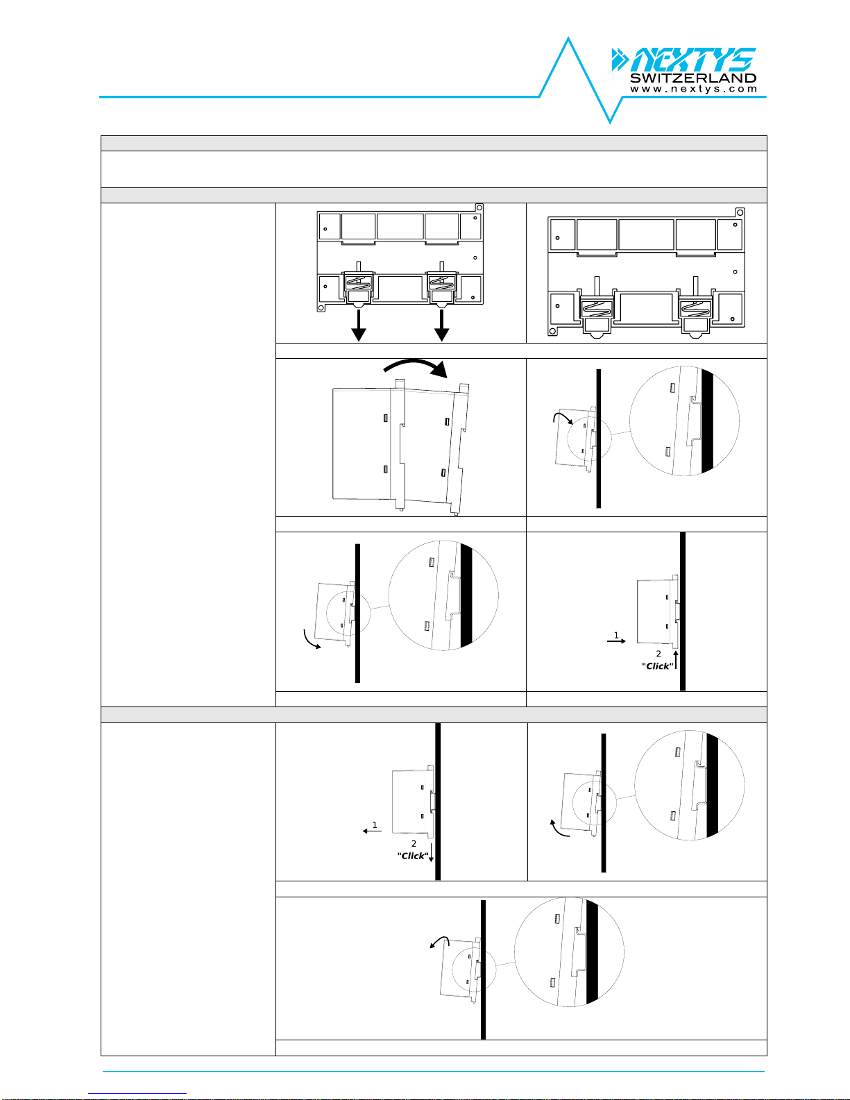
Mounting / Dismounting Instructions
For DIN rail fastening according to IEC 60715 TH35-7.5(-15)
Mounting as shown in figure, with input terminals on lower side, with suitable cooling and maintaining a proper distance between adjacent devices as specified in the I.S.
manual of each family.
DIN rail mounting:
1. Pull down to release and unlock the
slide clamps.
2. Tilt the unit slightly backwards.
3. Fit the unit over the top edge of the rail.
4. Slide it downward until it hits the stop.
5. Press toward top the two slide clamps
for locking
1
2
3
3
4 & 5
DIN rail dismounting:
1. Pull down to release and unlock the
slide clamps.
2. Tilt the unit upward
3. Unhook the unit from the rail
1 & 2
3
PSH150 user manual rev4
Page 14/15
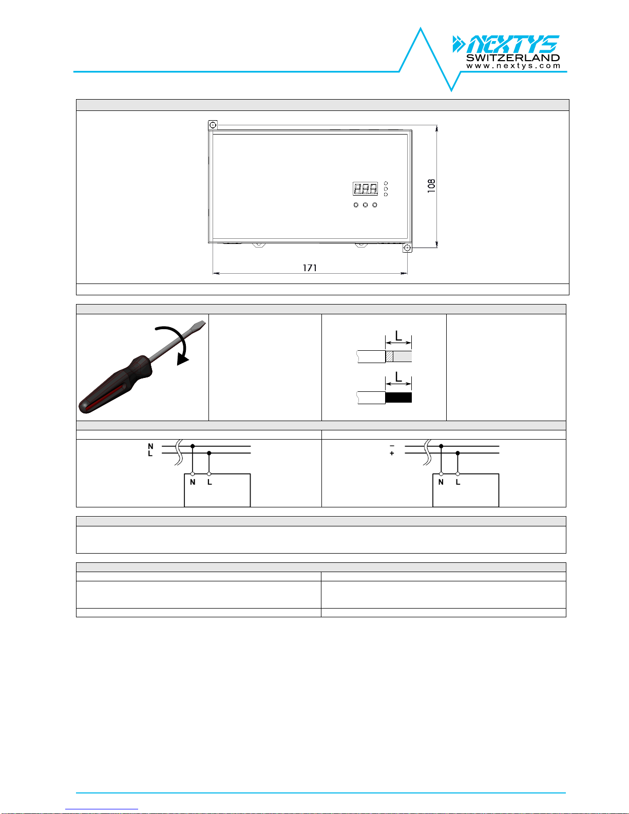
Wall / Panel mounting
It is possible install directly on panel or wall using the appropriate fixing points according the above image.
Recommended connecting cable
Recommended Tightening torque
Input / output connections
0.5-0.6Nm
4.42-5.30 lbf in
Auxiliary connections
Insertion force per pole
Max 3N or 0.674 lbf
Withdrawal force per pole
Min 1.5N or 0.337 lbf
Input / output connections
Solid: 2.5mm² / 12AWG
Stranded:1.5mm² / 12AWG
L: 6.0-7.5mm / 0.24-0.30in
Auxiliary connections
Solid: 0.5mm² / 20AWG
Stranded: 0.5mm² / 20AWG
L: 7.0-8.0mm / 0.27-0.315in
Input connection
AC Line
DC Line
Input protection
Fuses MCB 6A C curve
For USA and Canada, use the fuse type closest to the European equivalent type.
Surge protection: it is strongly recommended to provide external surge arresters (SPD) according to local regulations.
Environment
Operating temperature
Derating
- 40°C…70°C
5…95% r.H. non condensing
Overtemperature protection
See Figure 3 and Figure 4

PSH150 user manual rev4
Page 15/15
DECLARATION OF CONFORMITY
NEXTYS SA.
Via Luserte Sud 6, 6572 Quartino - Switzerland
Phone: +41-(0)91 840 14 46 / 840 14 48; Fax: +41-(0)91 840 14 47
E-mail: info@nextys.com
This Declaration of Conformity is suitable to the European Standard EN45014 "General criteria for supplier’s declaration of conformity".
We declare under our sole responsibility that the device included in this box, has passed all processing inspections and the final test and it is in conformity with the product
requirements, including all reference codes and supply specifications.
ROHS compliance: the product respects the EC requirements related to ROHS substances, according to “Restriction of Hazardous Substances” as per document
2011/65/UE
REACH compliance: the product respects the EC requirements related to REACH SVHC directive (2015)
Note: all the reported information comes from our suppliers, NEXTYS SA. has not run any test to evaluate if the specific elements are present.
All indicated devices are designed according to the latest Reference standards, if not expressly indicated through the official documents or files, they have been tested
through our internal pre-compliance testing. Consult directly on www.nextys.com the reference standards applied to each model.
Code Description
PSH150 10kV Isolation Programmable Power Supply IN 120…240Vac (110…400Vdc) / OUT 5…55Vdc – 12A Max (150W Max)
Certifications and approvals
Reference standards
2014/35/EU (2014) (Low Voltage Directive)
2014/30/EU (2014) (EMC directive)
UL508 (Safety Standards)
EN60255-27 (Safety Standards)
IEC60664-1 (Safety Standards)
EN50178 (Safety Standards)
EN61000-6-2 (Generic immunity standard for industrial environments)
- EN61000-4-2 (Electrostatic discharge immunity test)
- EN61000-4-3 (Radiated, radio-frequency, electromagnetic field immunity test)
- EN61000-4-4 (Electrical fast transient/burst immunity test)
- EN61000-4-5 (Surge immunity test)
- EN61000-4-11 (Voltage dips, short interruptions and voltage immunity test)
EN61000-6-4 (Generic emission standard for industrial environments)
- EN55022 (CISPR22 - EMC)
- EN55011 (CISPR11 - EMC)
- EN61000-3-2 (Limits for harmonics current emissions)
Date: 10.10.2016
Place: Quartino, Switzerland
The product manager
Marius Ciorica
 Loading...