

NUPSxx Series
Instruction Manual
NUPSxx Series V5.0
www.nextys.com
Page 1/5
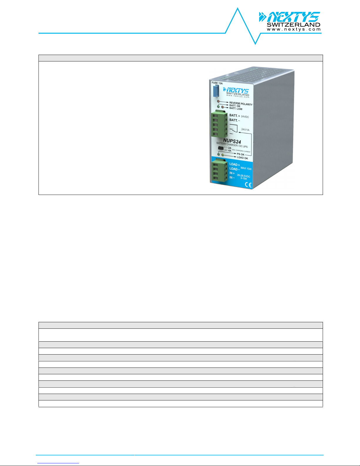
NUPS12 and NUPS24 – Battery Charger and DC UPS module
Main Features:
Accessory for the charging of a 12 or 24 Vdc battery
Suitable for power supplies with adjustable output
To be used with Lead acid batteries ONLY
Allows to feed the load and to charge the battery at once
Built-in battery protection fuse
“Low battery” cut-off system
INDEX
Page
Installation Requirements
2
Declaration of Conformity
2
User Instructions
3
Connections
4
Dimensions
4
Distances
4
Mounting
4
Dismounting
5
Input Connections
5
Environment
5
Accessory Device
5
NUPSxx Series
Instruction Manual
NUPSxx Series V5.0
www.nextys.com
Page 2/5
READ THIS CAREFULLY BEFORE INSTALLATION!
LEGGERE ATTENTAMENTE PRIMA
DELL’INSTALLAZIONE!
A LIRE ATTENTIVEMENT AVANT L’INSTALLATION!
Before operating, read this document thoroughly and retain
it for future reference.
Non-respect of these instructions may reduce
performances and safety of the devices and cause danger
for people and property.
The products must be installed, operated, serviced and
maintained by qualified personnelin compliance with
applicable standards and regulations.
Don’t open the device, it does not contain replaceable
components, the tripping of the internal fuse (if included) is
caused by an internal failure.
Don’t repair or modify the device, if malfunction or failure
should occur during operation, send unit to the factory for
inspection. No responsibility is assumed by Nextys SA for
any consequences deriving from the use of this material.
Prima dell’installazione, leggere attentamente questo
documento istruzioni e conservarle per future consultazioni.
L’inosservanza delle presenti istruzioni può compromettere le
caratteristiche e la sicurezza dell’apparecchio e causare
pericolo per le persone e le cose.
Il prodotto deve essere installato, utilizzato e riparato da
personale qualificato e nel rispetto delle normative vigenti.
Non aprire il prodotto, esso non contiene componenti sostituibili,
il guasto del fusibile interno (se previsto) è causato da un
guasto interno. Non tentare di riparare o modificare il prodotto,
se durante il funzionamento si verificano guasti o anomalie,
inviarlo al produttore per il controllo.
Nextys SA non si assume nessuna responsabilità per
qualunque conseguenza derivante dall’uso di questo materiale.
Lisez ces instructions avant l'installation, conservez ce
manuel pour référence future.
Défaut de se conformer à ces instructions peut affecter les
caractéristiques et la sécurité du dispositif de danger et de
causer aux personnes ou aux biens.
Les produits doivent être installés, exploité et entretenus par
personnel qualifié et en conformité avec les règlements.
N'ouvrez pas le produit, il ne contient aucune pièce réparable,
le déclenchement du fusible interne (le cas échéant) est
causé par un défaut interne. Ne pas essayer de réparer ou
modifier le produit; si des défaillances se produisent pendant
le fonctionnement ou les dysfonctionnements, le retourner au
fabricant pour inspection. Nextys SA n'assume aucune
responsabilité des conséquences éventuelles découlant de
l'utilisation des produits.
CAUTION
ATTENZIONE
AVVERTISSEMENT
RISK OF BURNS, EXPLOSION, FIRE, ELECTRICAL
SHOCK, PERSONAL INJURY.
Never carry out work on live parts! Danger of fatal injury!
The product’s enclosure may be hot, allow time for cooling
product before touching it. Do not allow liquids or foreign
objects to enter into the products.
To avoid sparks, do not connect or disconnect the device
before having previously turned-off input power and wait for
internal capacitors discharge (minimum 1 minute).
RISCHIO USTIONI,ESPLOSIONE, INCENDIO, SCOSSA,
LESIONI GRAVI.
Non effettuare mai operazioni sulle parti sotto tensione! Pericolo
di lesioni letali! Il contenitore può scottare, lasciar quindi
raffreddare il dispositivo prima di toccarlo. Non far entrare liquidi
o oggetti estranei nel dispositivo.
Per evitare scintille, non collegare o scollegare
l'apparecchiatura prima di avere tolto tensione di ingresso e
prima che sia avvenuta la scarica dei condensatori interni (min.
1 minuto).
RISQUE DE BRULURES, EXPLOSION, INCENDIE,
ELECTROCUTION, DOMMAGE AUX PERSONNES.
Ne jamais effectuer des opérations sur les parties sous
tension! Danger de mort! Le récipient peut produire des
brulures, le laisser refroidir avant de toucher l'appareil. Ne
faites pas pénétrer des liquides ou des corps étrangers dans
l'appareil. Pour éviter des étincelles, ne pas connecter ou
déconnecter l'équipement jusqu'à ce que vous avez supprimé
la tension d'entrée et avant qu'elle n'ait lieu de décharge des
condensateurs internes (minimum 1 minute).
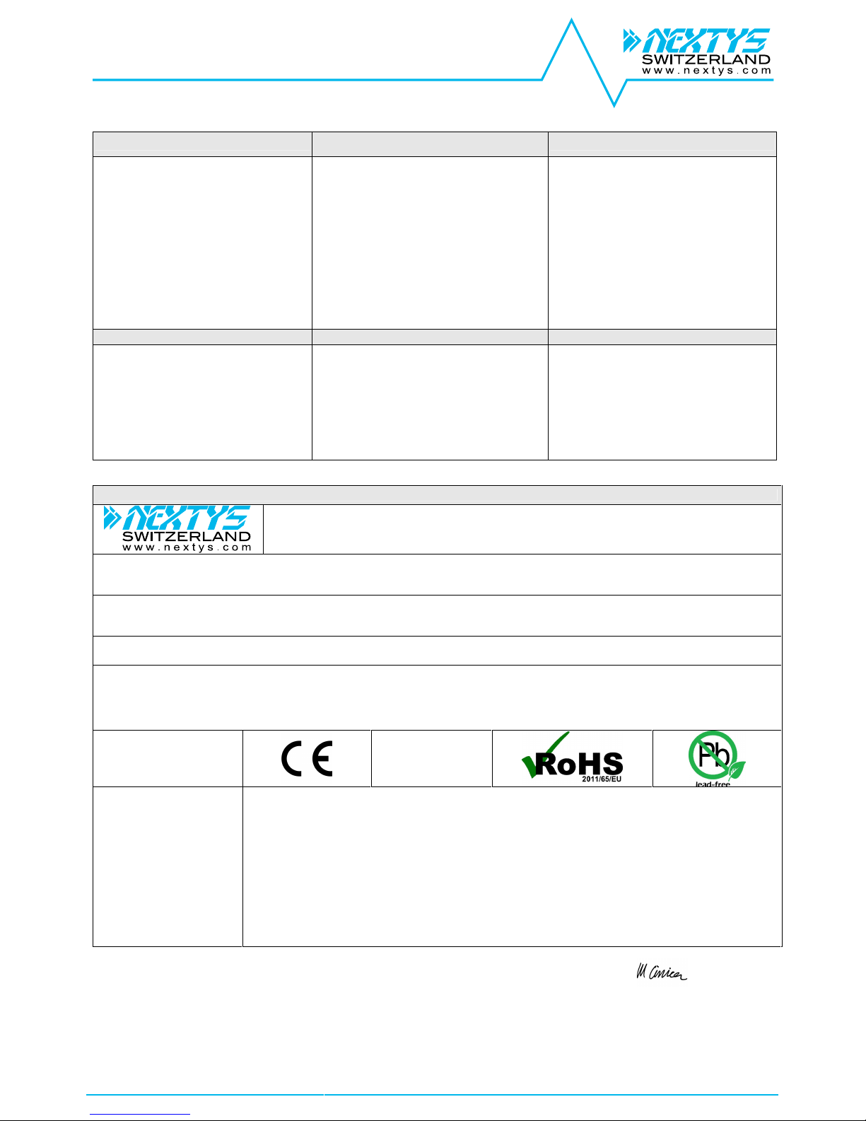
DECLARATION OF CONFORMITY
NEXTYS SA.
Via Luserte Sud 6, 6572 Quartino- Switzerland
Phone: +41-(0)91 840 14 46 / 840 14 48; Fax: +41-(0)91 840 14 47
E-mail: info@nextys.com
This Declaration of Conformity is suitable to the European Standard EN45014 "General criteria for supplier’s declaration of conformity".
We declare under our sole responsibility that the device included in this box, has passed all processing inspections and the final test and it is in conformity with the product
requirements, including all reference codes and supply specifications.
ROHS compliance: the product respects the EC requirements related to ROHS substances, according to “Restriction of Hazardous Substances” as per document 2011/65/UE
REACH compliance: the product respects the EC requirements related to REACH SVHC directive (2015)
Note: all the reported information comes from our suppliers, NEXTYS SA. has not run any test to evaluate if the specific elements are present.
All indicated devices are designed according to the latest Reference standards, if not expressly indicated through the official documents or files, they have been tested through
our internal pre-compliance testing. Consult directly on www.nextys.com the reference standards applied to each model.
Code Description
NUPS12 Battery Charger and DC UPS module IN 13– 15.5Vdc / OUT 10 - 15Vdc 10A
NUPS24 Battery Charger and DC UPS module IN 26– 28.5Vdc / OUT 20 - 28 Vdc 10A
Certifications and approvals
Reference standards
2014/35/EU (2014) (Low Voltage Directive)
2014/30/EU (2014) (EMC directive)
EN60950-1:2006 /A2:2013 (Safety Standards)
UL508 (Safety Standards)
EN61000-6-2:2005 (Generic immunity standard for industrial environments)
- EN61000-4-2:2008 (Electrostatic discharge immunity test)
- EN61000-4-3:2006 /A2:2010 (Radiated, radio-frequency, electromagnetic field immunity test)
- EN61000-4-4:2012 (Electrical fast transient/burst immunity test)
- EN61000-4-5:2014 (Surge immunity test)
- EN61000-4-11:2004 /A1:2010 (Voltage dips, short interruptions and voltage immunity test)
EN61000-6-3:2007 /A1:2011 (Generic emission standard for residential environments)
- EN55022:2010 (CISPR22 - EMC)
- EN55011:2009 /A1:2010 (CISPR11 - EMC)
Date: 25.02.2016
Place: Quartino, Switzerland
The product manager
Marius Ciorica
NUPSxx Series
Instruction Manual
NUPSxx Series V5.0
www.nextys.com
Page 3/5
USER INSTRUCTIONS
1) Description: DIN rail mountable primary switched-mode power supply with 90...264Vac (110…345Vdc) input, suitable for Single phase main line and DC line.
Functions:
Battery +: connection to battery PLUS
Battery –: connection to battery MINUS
PS OK connector: connection to SPDT contact for operating status/failure remote alarm (P.S. OK signal)
Load +/-: connection to load PLUS /MINUS
IN +/-: connection to power supply output PLUS /MINUS
Battery fuse: protects the battery and its cables against dangerous over currents. 15A Mini car Blade Fuse factory supplied is the max. allowed value, it
can be replaced with a lower value fuse for a better protection with small batteries.
Note: if the fuse blows and if the module is fed only by the battery and without any voltage connected to IN+, IN– terminals, all LEDs of the
module are turned off.
Charging circuitry: regulates and controls battery charging current.2A or 4A charging current can be selected (see Fig.7).
It’s recommended to use 2A with batterycapacity up to 20Ah and (if a faster charging time is not required) and 4A current with battery
capacity 20-45Ah max.
PS OK: green LED, when it lights indicates that power supply is OK and that it is feeding the load and keeping battery under charge too.
PS OK off: indicates either that the power supply is turned off for AC mains black-out, or is disconnected form the AC mains, or that its output is
overloaded and thus output isturned off for a short circuit - overload, or that the power supply failed.
LOAD OK: yellow LED, when it lights on indicates that the load receive power, either from the P.S. (PS OK LED On) or frombattery (PS OK LED Off).
BATT. OK: green LED, with the power supply turned off or disconnected indicates that the battery is connected and charged.
Attention: with the power supply connected and active BATT. OK is always turned on even if the battery is not connected.
BATT. LOW: red LED, indicates that the battery is charged, increasing current required by the load and/or increasing the battery discharge.
BATT. LOW LED lights on together with BATT OK, and its light intensity can vary depending on current required by the load, or blink if
loads are switched on / off, due to unavoidable battery voltage variations depending on applied load.When BATT. LOW LED is lit, it is
recommended to safely shut down the load, in order to avoid unexpected power loss.
Failure contact: at 1A/24V SPDT contact switches when the battery starts back-up feed of the load. The remote signal informs that the system is no more
fed by the DC powersupply e.g. for a fuse failure or for a power supply failure, thus giving a warning even if there is not a general and
visible black-out but only a local failure.
NUPSxx restart after a long duration black out with low battery. In such condition the module has disconnected the battery from the load (to prevent total discharge and thus
battery damage). It can be started up only by feeding IN+, IN – with a24Vdc source (e.g. the power supply or a battery). By connecting only the discharged battery to
BATT. +/- terminals the module cannot be restarted. If the module is feeding the load from the back-up battery and if a short circuit makes the battery protection fuse to
blow, the module can be re-started (after fuse replacement) only by first connecting a 24Vdc power source to IN+,IN – terminals.
2) Installation: use DIN-rails according to EN60715. Installation should be made vertically (see Fig.4). For better device stability fix the rail to the wall close to the point where
the device is to be mounted. In order to guarantee sufficient convection, we recommend observing a minimum distance to other modules (see Fig.3).
The device is provided with a thermal protection; a limited air flow can cause the thermal protection tripping. The SMPS automatically restarts after cooling.
To get normal operation reduce the temperature of the air surrounding the power supply, increase the ventilation or reduce the load (see Fig.8)
3) Connections: the device is equipped with pluggable screw terminals. To avoid sparks, do not connect or disconnect the connectors before having previously turned-off input
power and waited for internal capacitors discharge (minimum 1 minute).
In order to comply with UL certification, use appropriate copper cables of indicated cross section, designed for an operating temperatures of:
60°C for ambient up to 45°C
75°C for ambient up to 60°C
90°C for ambient up to 70°C
Strip the connecting ends of the wires according to the indication and ensure that all strands of a stranded wire enter the terminal connection (see Fig.5)
4) Battery protection:protects the battery and its cables against dangerous overcurrents. 15A Mini car Blade Fuse factory supplied is the max. allowed value, it can be
replaced with a lower value fuse for a better protection with small batteries (see Fig.6)
5) DC input connection: connect L terminal to (+) positive pole, N terminal to (-) negative pole and I terminal to GND. Rated voltage 110...345Vdc.
The device is also suitable for photovoltaic or wind turbine applications (see Fig.7).
6) Output connection: Thedevice is suitable for SELV andPELV circuitry.
Check Uout beforeconnecting the NUPSxx to the load. With output voltage set to the max. value, the continuous current must not exceed the nominal current 10A max.
7) Protection: the device is protected against
REVERSE battery connection: a red LED indicates that battery is connected with reversed polarity.
Protection diode: it avoids the voltage and current supplied by the battery to circulate through the power supply output circuitry and prevents failures due to reverse
polarity connection.
Deep discharge battery protection circuit: this circuit disconnects the battery when its voltage drops under DDV voltage, to avoid battery damage.
8) GENERAL INFORMATION ON BATTERIES
Rated voltage: is the voltage that the battery can supply in condition of full charge and rated current. Battery voltage without load is always higherof rated voltage.
Capacity: given in Ah (Ampere / hour) measured at 25°C/ 77°F.(e.g. at 10Ah battery can supply 10A for 1 hour or 1A for 10 hours).
Charging current: is the current to be applied to charge the battery, usually indicated by the manufacturer. A charging current higher than specified can damage the battery or
shorten its life, a too low charging current results in a too long charging time and uncompleted or partial charge, thus reduced Ah capacity.
Charging current of sealed lead batteries would never exceed 20% of capacity of the battery. The battery limits by itself the charging current supplied by the battery charger,
depending on its charge status.Only when the battery is completely discharged it’s possible to apply the maximum charging current.
Note: when choosing the capacity of the battery, consider that real capacity indicated by manufacturers can vary compared with rated capacity depending quality and cost,
capacity is always given for new battery at 25°C/77°F, but during battery life it’s capacity decreases due to ageing, even if the battery is not used, so calculate battery capacity
and duration considering the worst operating conditions.
Discharge voltage: the right charging voltage value is given by the manufacturer; generally thevoltage/current source must be capable to supply a voltage 10-15% higher than
rated voltage of the battery. If charging voltage is lower than +10% of battery rated voltage, charging time increases and produce an uncompleted charge and thus a reduced
capacity. Charging voltages higher than +20% of rated voltage can damage the battery and shortens its life.
Charging time: varies according to charging current/voltage. Consider a minimum charging time of 3-4 hours after a battery discharge.
Discharged battery: a battery is considered discharged when its voltage, measured applying a 50% load, is lower than -10% of rated voltage, or when voltage measured with
no load is lower than rated voltage.
Total discharge: when a battery gives a voltage between 0 - 60% of rated voltage, it’s totally discharged. Total or deep discharge reduces battery life and must be avoided.
Disconnect the battery from the load when voltage is lower than e.g. 18V/9V in at 24V/12V battery.
Operating temperature: for a long duration of the battery operating temperature must be kept within 10°C/+50°F…30°C/+ 86°F. Battery duration decreases outside this
range. At low temperatures the battery might not supply rated Ah, because electrochemical reaction are less efficient.
Overload–short circuit battery protection: battery and its connecting cables must be protected with overcurrent protection devices (fuses, circuit breakers, etc.) able to cutoff dangerous currents.

NUPSxx Series
Instruction Manual
NUPSxx Series V5.0
www.nextys.com
Page 4/5
Fig.1
Connections
Fig.2
Dimensions
Fig.3
Distances
Just for reference
(1) DC input
(2) DC output (load)
(3) Battery connection
(4) Diagnostic Outputdry contact
NC Power Supply OK
(5) Green LED: Power Supply OK
(6) Yellow LED: Load OK
(7) Charging current jumper
(8) Green LED: Battery OK
(9) Red LED: Battery Low
(10) Red LED: Batt. Reverse polarity
Input DC Line:
IN + = + Positive DC
IN -= - Negative DC
Output:
LOAD + = Positive Load
LOAD - = Negative Load
BATT + = Positive DC Battery
BATT - = Negative DC Battery
Dry contact = NC
Dry contact = NO
Dimension
W
D
H
mm (inc)
54.0 (2.16)
110.0 (4.33)
115.0 (4.52)
Distance
A
B
mm (inch)
20 (0.8)
50 (2.0)
Fig.4
Mounting / Dismounting Instructions
For DIN rail fastening according to IEC 60715 TH35-7.5(-15)
Mounting as shown in figure, with input terminals on lower side, with suitable cooling and maintaining a proper distance between adjacent devicesas specified in the I.S.
manual of each family.
Mounting:
1
2
1.Tilt the unit slightly backwards.
2.Fit the unit over the topedge of the rail.
3.Slide it downward until it hits the stop.
4.Press against the bottom for locking.
3
4

NUPSxx Series
Instruction Manual
NUPSxx Series V5.0
www.nextys.com
Page 5/5
Dismounting:
1.Pull down the slide clamp lever
2.Tilt the unit upward
3.Unhook the unit from the rail
1 & 2
3
Fig.5
Recommended connecting cable
Recommended Tightening torque
0.5-0.6 Nm
4.42-5.30 lbf in
Solid: 2.5mm² / 12AWG
Stranded:1.5mm² / 12AWG
L: 6.0-7.5mm / 0.24-0.30 in
Fig.6
Input protection
Use Mini Car blade fuses 15A
Fig.7
Input connections
DC Line
Schematic connection
Fig.8
Environment
Operating temperature
Derating
- 40°C…50°C
5…95% r.H. non condensing
No derating
Note:
Data may change without prior notice in order to improve the product.
Please refer to the latest version of the "Instruction Manual" for each product by visitingwww.nextys.com
See also the products below that can be used in conjunction with NUPSxx units: (accessory device)
OR20 20A Active ORing controller
OR50 50A Active ORing controller
BU150U 150J Buffer Module
NBP30 Sealed Lead acid Battery pack
 Loading...