

Page 1
MASTER
HEA T TRACING CONTROL
TRACE
TM
OPERA TOR’S MANUAL
Page 2

MASTER
TRACE
Contents
1 Overview ..................................................................................................................................... 1.1
1.1 Use of This Manual .............................................................................................................................................. 1.1
1.2 Related Documents ............................................................................................................................................. 1.1
1.3 Conventions ......................................................................................................................................................... 1.1
1.4 Scope ................................................................................................................................................................... 1.1
1.5 Rev.A Enhancements ........................................................................................................................................... 1. 1
1.6 Overall Enhancements ........................................................................................................................................ 1.1
1.7 Shipping Content ................................................................................................................................................. 1.1
1.8 Theory of Operation.............................................................................................................................................. 1.2
2 Getting Started .............................................................................................................. ............. 2.1
2.1 Introduction ........................................................................................................................................................... 2. 1
2.2 Enable Heaters .................................................................................................................................................... 2.1
2.3 Enter Setpoints..................................................................................................................................................... 2 .2
2.4 Test Heater & Alarms ........................................................................................................................................... 2 .4
2.5 Monitor System Status.......................................................................................................................................... 2. 4
3 Product Description ...................................................................................................................3.1
3.1 Introduction ........................................................................................................................................................... 3. 1
3.2 Features and Benefits .......................................................................................................................................... 3.2
3.3 Control Module Specifications ............................................................................................................................. 3.3
3.4 Model Codes for Control Panels ....................................................................................................................... 3.19
4 Installation ...................................................................................................................................4.1
4.1 Control Panel Mounting ....................................................................................................................................... 4.1
4.2 RTD Sensor Wiring .............................................................................................................................................. 4.1
4.3 Ground Fault Protection ....................................................................................................................................... 4.1
4.4 Ground Fault Testing............................................................................................................................................ 4 .1
4.5 Power and Heater Wiring..................................................................................................................................... 4.1
4.6 Ground Connection .............................................................................................................................................. 4.1
4.7 Safety Ground....................................................................................................................................................... 4.2
4.8 Control Power Wiring ........................................................................................................................................... 4.2
4.9 Commissioning ................................................................................................................................................... 4.2
5 Operation .....................................................................................................................................5.1
5.1 Control Modules .................................................................................................................................................. 5 .1
5.2 Interface Modules - ML100 & MR100 .................................................................................................................. 5.6
5.3 Responding to Alarms ........................................................................................................................................ 5.9
5.4 Setpoint Values Menu: Single-Phase Modules ................................................................................................ 5.10
5.5 Setpoint Values Menu: Three-Phase Modules (1- and 5-point only)................................................................. 5 .11
5.6 Measured Values Menu: Single-Phase Modules ............................................................................................ 5.12
5.7 Measured Values Menu: Three-Phase Modules .............................................................................................. 5.13
5.8 Interface Module - MR100 for Windows CE ...................................................................................................... 5.14
6 Programming & Setup ................................................................................................................6.1
6.1 Getting Started...................................................................................................................................................... 6.1
6.2 Program Enable ................................................................................................................................................... 6.1
6.3 Module List/Communication Map ........................................................................................................................ 6.1
6.4 Heater Enable ...................................................................................................................................................... 6.1
6.5 Example: Change the Setpoint for Heater 3-2 to 50°C ....................................................................................... 6.1
7 Networking Modules ..................................................................................................................7.1
7.1 RS-485 Communications in Modbus RTU ......................................................................................................... 7.1
7.2 RS-485 Wiring ...................................................................................................................................................... 7. 1
7.3 Removing a Control Module from the Network ................................................................................................... 7.1
7.4 Adding a Control Module to the Network.............................................................................................................. 7.1
7.5 Communication With Third Party Equipment ..................................................................................................................7.1
7.6 Baud Rate ............................................................................................................................................................ 7.3
7.7 Ethernet Communication in Modbus TCP and MasterTrace Heat Tracing Panel Option “ETH”........................ 7.3
Page 3

TRACE
7.8 Ethernet Communication in EtherNet/IP ............................................................................................................. 7.3
7.9 MC100 for Internet ................................................................................................................................................ 7.4
ContentsMASTER
8 Service & Testing ....................................................................................................................... 8.1
8.1 Troubleshooting Hints ......................................................................................................................................... 8.1
8.2 Field Tests............................................................................................................................................................ 8.1
8.3 Field Repairs ........................................................................................................................................................ 8.2
Appendix A Display Message Details - Setpoints ...................................................................... A.1
Setpoints: Operating Values ...................................................................................................................................... A.1
Setpoints: Heater Setup Menu ................................................................................................................................... A.6
Setpoints: System Setup Menu.................................................................................................................................. A.8
Setpoints: Test Menu................................................................................................................................................ A.17
Appendix B Display Message Detail - Measured ...................................................................... B .1
Measured Values: Operating Values ......................................................................................................................... B.1
Measured Values: Statistics Menu ............................................................................................................................. B.3
Appendix C Summary of Alarms and their Causes .................................................................... C.1
Appendix D T ypical Wiring Diagrams.......................................................................................... D.1
MS-1DXH0 .................................................................................................................................................................. D.1
MS-1DIN2 ...................................................................................................................................................................D.1
MS-1TXH0 .................................................................................................................................................................. D.1
MS-2DXH0 .................................................................................................................................................................. D.2
MS-2DIN2 ...................................................................................................................................................................D.2
MS-5ADXH0................................................................................................................................................................ D.2
MS-5ADIN2 ................................................................................................................................................................. D.3
MS-5A TXH0................................................................................................................................................................. D.3
MS-10ADXH0..............................................................................................................................................................D.4
MS-10ADIN2 ............................................................................................................................................................... D.4
MS-10ADIN2T.............................................................................................................................................................D.5
MS-10ADIN2X ............................................................................................................................................................. D.5
Driving Contactors ...................................................................................................................................................... D.6
Serial Communication 1 ............................................................................................................................................ D. 6
Serial Communication 2 ............................................................................................................................................ D. 7
Appendix E Freeze Protection .................................................................................................... E.1
Appendix F Wireless and Wired RTD ..........................................................................................F.1
Appendix G MR100 for Windows CE........................................................................................... G.1
Warranty .......................................................................................................................... Back Cover
Page 4

MASTERTRACE
1 Overview
1.1 Use of This Manual
Reading a lengthy instruction manual on a new product is
not a task most people enjoy. To speed things up,
Chapter 2, Getting Started, provides a step-by-step
tutorial for a heat trace application. Chapter 4, Installation, discusses important mounting and wiring issues for
reliable operation. Detailed information relating to switch
and output ratings, accuracy and so forth are detailed in
Section 3.3, Specification. The remainder of this manual
should be read and kept for reference to provide the
maximum benefit of the MasterTrace Controls.
Chapter 1 Overview
very important in protecting plant equipment in the event
of a GF which can cause fires . It is required by electrical
code (NEC and CEC) on electric heat trace.
The overall height on external switching models MS5ADXH0, MS-5ATXH0 and MS-10ADXH0 have been
reduced by half from the previous models which will
improve control panel servicing.
Service and replacement of control modules take minutes
instead of hours with the addition of detachable terminals.
All terminals can be unplugged without a screw driver.
1.2 Related Documents
The following documents are attached with this manual
and located inside the control panel.
s Layout Drawing(s)
s Wiring Diagram(s)
1.3 Conventions
The following conventions are used in this manual.
? User Changeable Values
& Retrieved Data
[ ] Key Press
V~ VAC (AC Voltage)
_ _ _ VDC (DC Voltage)
Warning Statement
1.4 Scope
This manual describes control panel installation, startup
information and operation for:
s MasterTrace one and two point control modules
s MasterTrace Rev.A versions of five and ten point
modules. These models are identified by the addition of
the letter A in the model number. (ie: MS-AD,
MS-10ADXH0). These models are not replacement
compatible with previous models.
s MasterTrace local and remote display modules
1.5 Rev.A Enhancements
New enhanced Rev.A models have been introduced for
five and ten point models. These models include MS5ADXH0, MS-5ATXH0, MS-5ADIN2, MS-10ADXH0
and MS-10ADXH0 which replaces the previous models
designated without the A.
A GF test function has been added to verify that GF
monitoring is functional. The user may set the GF testing
period and is notified if a GF test fails. GF monitoring is
1.6 Overall Enhancements
These enhancements pertain to all controller models
described in this manual. These controllers are identified
by the marking REV. D1-xx-xx on the product
nameplate. Previous models identified by the marking
REV. D-xx-xx on the product nameplate do not
contain these enhancements.
Alarm contacts have been changed on all controller
models to one solid-state and one mechanical alarm
contact. Each contact may be configured normally open
or closed by the user. The mechanical contact is dual
rated hazardous and ordinary areas. The alarm light
indicator can be programmed by the user to turn on, off
or flash on alarm.
Communication baud rate is user settable to one of the
following: 600,1200, 2400, 4800 and 9600. Faster baud
rates will provide quicker response times on the remote
display.
The MS-xDXN0 type models which were used for
external contactor drive instead of solid-state relays are
discontinued for new applications. The MS-xDXH0 or
MS-xADXH0 models which are used for external solidstate relays can also be used for driving contacts with the
addition of the SSR/HCC board. More details on driving
contacts with this board is shown in Appendix D, page
D6.
1.7 Shipping Content
Control panels are usually packaged in a wooden crate,
sealed in plastic to minimize possiblity of damage. Check
the crate for damage, or other signs of rough handling or
abuse. If damaged, notify the shipping carrier at once.
Control Panel
Panel Drawings (Located inside the control panel)
Instruction Manual (Located inside the control panel)
Warranty Card (Located inside the control panel)
1.1
Page 5
MASTERTRACE Chapter 1 Overview
1.8 Theory of Operation
Controller functions are controlled by a microprocessor
that measures all analog signals and logic inputs, control
heater outputs and alarm contacts, and reads all user
input including communications and outputs to the
faceplate display and LEDs. The remainder of this chapter
describes the algorithms and operation of some of the
controller functions.
RTD Sensing
An RTD changes its resistance in a precision relationship
to temperature. This resistance is sensed by passing a
constant current through the RTD and measuring the
resulting voltage across the RTD (resistance = voltage/
current). The voltage appearing across RTD terminals also
includes the resistance of the inter-connecting wiring to
the RTD, which varies with wire length, size and ambient
temperature. By using a three-wire sensing scheme and a
lead resistance compensation circuit, the lead resistance
is cancelled out to give a voltage proportional to the true
RTD sensor temperature.
RTDs respond in a known but non-linear fashion to
temperature, which if uncorrected could lead to significant
errors over the temperature range of the controller.
Consequently, some means are needed to convert the
input voltage to a linear and useful range. The CPU
applies gain, offset and non-linearity corrections through
a linearization algorithm.
Current, Ground Fault and Voltage Sensing
Current transformers and high impedance voltage dividers
are used to scale-down the incoming heater current,
ground fault current and voltage. All three signals are
then passed through a full wave rectifier and filter to
obtain a DC signal. The DC signals are then converted to
digital values by a 10 bit A/D converter before finally
being passed on to the CPU for analysis.
Each of the three DC signals are sampled 300 times with
zero cross synchronization so that the sampling covers an
exact span of ten power cycles. This is to ensure that
heater current values are consistently measured when the
heater output cycle is modulated by the powerlimit and
proportional control functions.
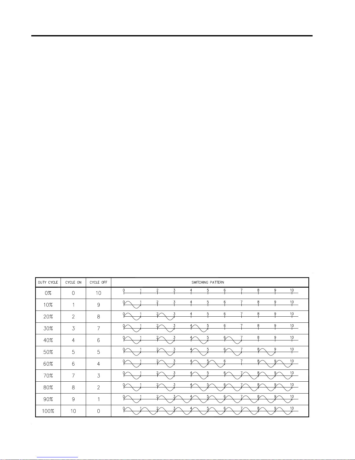
Powerlimit
The powerlimit function allows the heater to operate
below its rated power by cycle modulation. Cycle
modulation is accomplished by controlling the integral
number power cycles into the heater over a periodic time
frame. The MasterTrace control uses a ten cycle time
frame. The integral number of power cycles per time frame
is called a duty cycle. With a ten cycle time frame, there
are ten duty cycles possible. For each duty cycle, there is
a fixed pattern that defines the number of power cycles in
which the heater is on and off. This is shown in figure 1.1.
Figure 1.1 Cycle Modulation - 10 Cycle Frame
1.2
Page 6
MASTERTRACE
secondsin time
£=
t
Cycle modulating the current through the heater has the
effect of turning the heater on and off rapidly and
therefore, power output is reduced in the long run. Since
the switching is zero-cross controlled, the controller
knows exactly when power cycles start and finish. Zerocross switching also helps reduce power harmonics that
generate unnecessary interference.
The heater current (average current) measured by the
controller while cycle modulation is in effect may be
approximated as follows:
Heater Current at 100% x Duty Cycle = Average Current
Chapter 1 Overview
0)(0)(
teiftd
)(
te
)(
td
DB(t)
cycleduty )(Where
=
td
tDB
<<=
tDBteif
³=
)()(1)(
tDBteiftd
°=
Ts
C)( peratureheater tem
T(t)
TTs-T(t)e(t)
°=
C)(
°==
=
(1) )()(0
cycle)C/duty (in factor deadband)(
C)( emperaturesetpoint theater
°=
When powerlimit is enabled, a powerlimit current is set by
the user. This is essentially the desired average current.
The powerlimit control algorithm ensures that the actual
average current will not exceed the powerlimit setting
while optimizing the maximum duty cycle possible. When
the average current exceeds the powerlimit setting, the
duty cycle is reduce by 10%. When the average current is
below the powerlimit setting, the duty cycle is increased
by 10%. Before the algorithm increases or decreases the
duty cycle, the controller waits until the heater current
has reached steady-state at the current duty cycle setting.
If the heater is initially off and the controller calls for heat,
the duty cycle starts at zero and increases by 10%
increments until it reaches a steady-state value. This
ramping up effect provides a current-driven softstart
whenever the controller calls for heat.
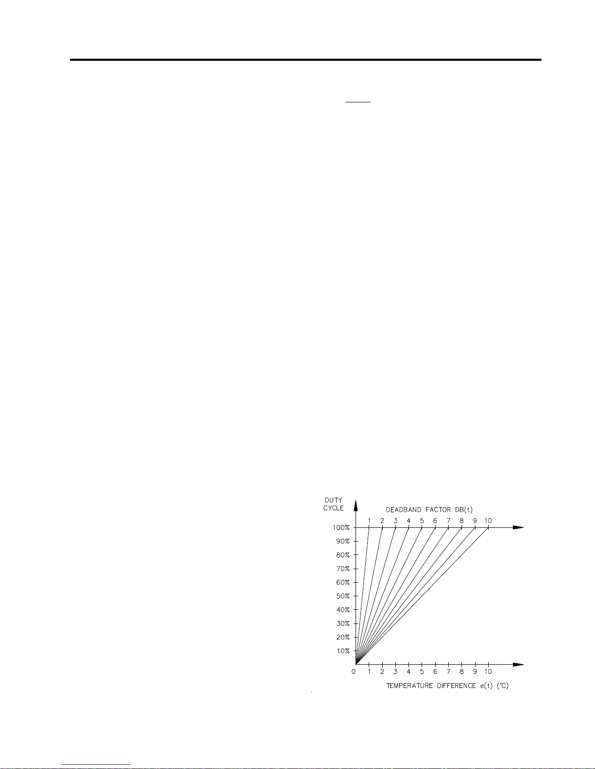
Proportional Control
Unlike on/off control where the heater is fully on or off,
proportional control can partially turn on the heater. The
heater output is proportional to the difference between
actual temperature and heater setpoint. The relationship is
expressed as follows:
setpoint. Every hour after power up, the controller
calculates the absolute values of the temperature
differences e(t) and sums them during the hour. Then the
total absolute temperature difference is divided by the
number of temperature readings taken during the hour.
The result is called the Average Absolute Temperature
Difference (AATD) for the hour. If current AATD is
smaller than the AATD in the previous hour, the
deadband factor will be increased or decreased in the
same direction. If current AATD is larger than the AATD
in the previous hour, the deadband factor will be
increased or decreased in the reversed direction. At
steady state, the deadband factor used will fluctuate
around a optimum value.
Figure 1.2 shows the relationship between the proposed
heater on duty cycle and the temperature difference for
different deadband factors used.
Figure 1.2 Proportional Control
Duty Cycle vs. Temperature Difference
(actual temperature heater setpoint) x k = heater output
where k is the proportional gain
To partially turn on the heater, the proportional control
function uses cycle modulation in the powerlimit function.
By incorporating cycle modulation into the proportional
control equation, the algorithm is expressed using the
Equation 1.
The deadband factor DB(t) is a time constant that
determines the slope of change of the proposed heater on
duty cycle with the temperature difference. It is adjusted
between 1 to 10 each hour to minimize the difference
between the measured temperature and the temperature
1.3
Page 7
MASTERTRACE Chapter 1 Overview
On/Off Control with Deadband
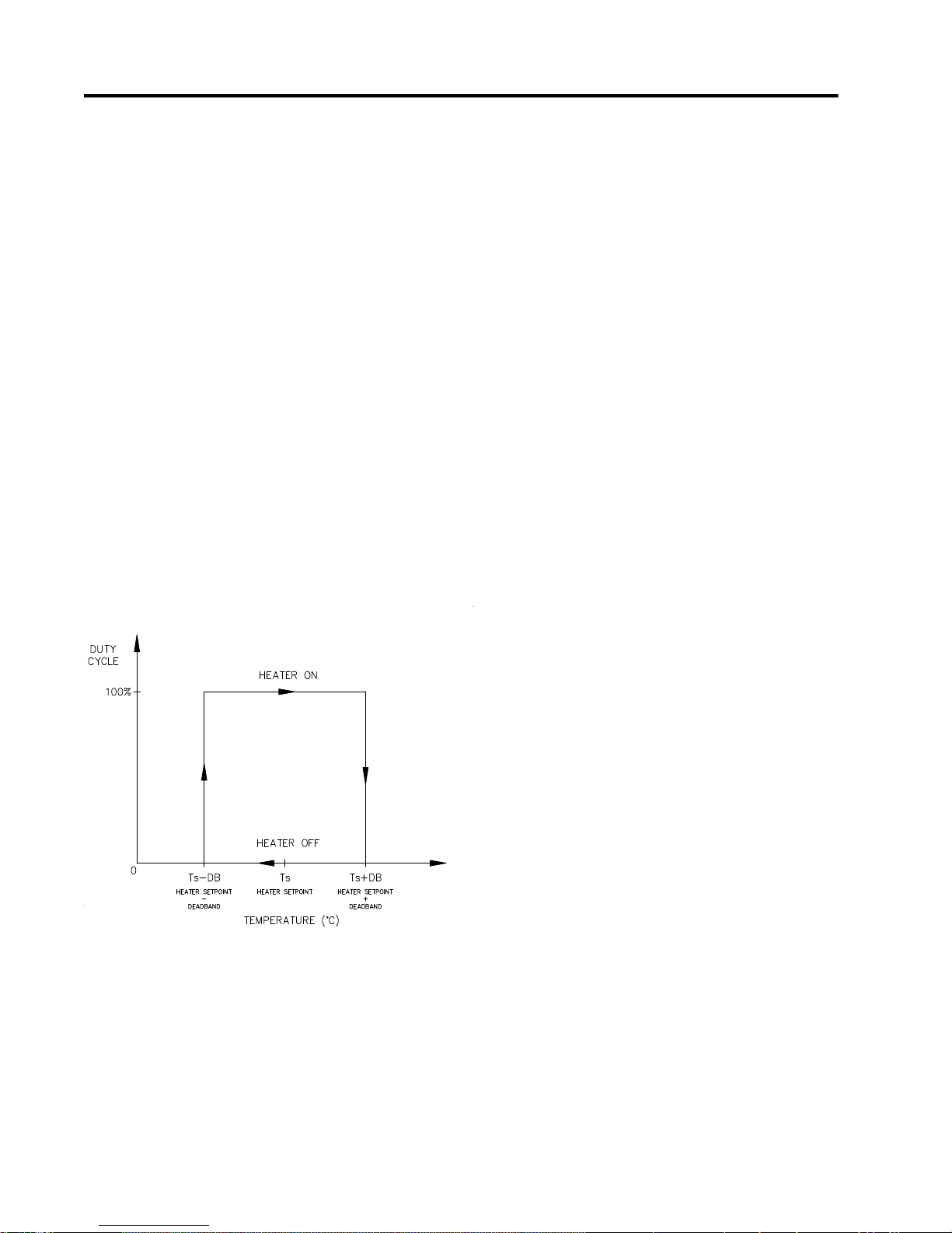
The default control mode of MasterTrace control is
deadband control or simply on/off control with the
proportional control setting turned off. On/off control
without deadband (that is deadband set to 0 C° or 0 F°;
note that these units denote the temperature differential
with ° placed to the right of the unit) means that the
heater turns on when actual temperature is below setpoint
and turns off when above setpoint. However, this causes
oscillations when the actual temperature is very close to
setpoint. To eliminate oscillations, hysterisis is applied to
the on/off control by a deadband value. The on/off
control with deadband operation is described by the
hysterisis curve in figure 1.3. Assume that actual
temperature is well below (setpoint - deadband setting),
the controller calls for heat. As the actual temperature
rises, the controller continues to call for heat until the
actual temperature has reached (setpoint + deadband
setting). The controller no longer calls for heat and the
heater is off. As the actual temperature cools, the
controller does not call for heat until the actual
temperature reaches (setpoint deadband setting). The
hysterisis effect is controlled by the momentum of the
actual temperature rather than the temperature value itself.
Figure 1.3 On/Off Control with Deadband
1.4
Page 8

MASTERTRACE
2 Getting Started
2.1 Introduction
MasterTrace™ has many features which can provide trou-
ble-free operation of heat tracing installations. To realize all
the capabilities of control, it is recommended that all sections of the instruction manual are read.
An example is presented to illustrate how MasterTrace™
se t up a nd o perati on on a spec ific i nstall ation.
MasterTrace™ is easy to program and setting up a unit to
your specific requirements should be straight forward.
In this example an MS-10A control module and ML100/
MR100 front panel display/keyboard module are mounted
in an enclosure for control of 10 heavy oil feed lines. Consult Appendix A and B for further information on a specific
message or instructions.
Important Note:
For the programming of MasterTrace™ panel with an
MS-10A control module and MR100 for Windows CE
Touch Screen remote monitoring module, the same procedure outlined in this example applies. Consult Appendix
G - MR100 for Windows CE for further information.
Setpoint Required Range
Fluid maintain
temperature
50 °C 0-500°C/off
/none
Chapter 2 Getting Started
Example: Each heater will be programmed as:
Configuration:
1) 10 point panel and local display
2) 1 RTD per heater for temperature sensing
3) Mineral insulated (MI) cable is used for the heater.
4) Normally open alarm contact to remote programmable
control
5) Solid state switching 120 Vac@20A
6) Northern climate installation outdoors.
Operating temperatures: -40° to +40 °C
NEMA-4 weatherproof enclosure.
Install and commission the control in the following order:
STEP 1: Enable heaters (Section 2.2)
STEP 2: Program setpoints (Section 2.3)
STEP 3: Test heater and alarm operation (Section 2.4)
STEP 4: Monitor system status (Section 2.5)
2.2 Enable Heaters
After each control has been programmed with it’s unique
address, it is necessary to indicate which units are connected to the system and should be controlled. This is done
by enabling a heater circuit. To enable a heater circuit, the
operator must specify the heater number.
Low temperature
alarm
High temperature
alarm
Nominal heater
current
Nominal heater
voltage
Ground fault trip
current
Ground fault alarm
current
System exercise
time interval
Cost per Kilowatt
hour
Heater name HEAVY OIL
35 °C -50 to 500°C/off
no alarm -50 to 500°C/off
5 amps 0.0 to 100.0A
115 VAC 100 to 600 Vac
30 mA 10 to 1000mA
20 mA 10 to 1000mA
8 hours 1-24/off
$0.06 $0.01-$0.50
LINE
/off
/off
/off
16 characters
Note: When programming controls on a multipoint system
it is important that you always know which heater is being
accessed. Otherwise it is possible to program the wrong
heater control by accident.
Suppose in our example we have a 10-point controller with
heaters; 1-1, 1-2, 1-3 and 1-4 wired and programmed. The
remaining six unused heaters will be disabled and can be
used for easy system expansion at a later date.
The user can determine which heater the display is selected
to by pressing either the [SETPOINTS] key or the [MEASURED] key which will cause this message to be displayed
(the 2nd line and heater number may be different):
SELECT HEATER: 1-1
NONAME
Use the [VALUE ×] or [VALUE Ø] keys to select the appro-
priate heater number then press [STORE] to select a new
heater.
For this example, press [SETPOINT], select heater 1-1 using
[VALUE ×] or [VALUE Ø] keys then press [STORE].
2.1
Page 9

MASTERTRACE Chapter 2 Getting Started
To enable a heater circuit, press the [SETPOINTS] key once
to access the Setpoints Operating Values group of messages. Press [MESSAGE Ø] until a message similar to the
following appears:
HEATER ENABLED?
NO"
Use [VALUE ×] or [VALUE Ø] keys to toggle Heater 1-1
between YES and NO. When YES is displayed, press
[STORE].
Repeat this process, for the remaining heaters. For example,
to enable heater 1-2, select heater 1-2 first, then press the
[MESSAGE Ø] key to display:
HEATER ENABLED?
NO"
Select YES, then press [STORE] to enable heater 1-2.
Now that we have programmed control addresses and told
the master display which heater circuits are enabled, we can
program setpoints for each control. There are two ways to
do this on a multipoint system. Either go through each
control and program every value or choose a parameter like
temperature and program each control with that parameter
before proceeding with the next item.
Now that the MasterTrace™ control is ready for program-
ming, we will enter the setpoints for this example. For further information about the organization of all the messages
or for details on the range and application of each message
see Appendix A. It is not necessary to enter setpoints in
any particular order and any setpoint can be changed later.
2.3.2 Temperature Units °C/°F: Temperature values can be
displayed in degrees Celsius or Fahrenheit. In order to enter values in preferred units this selection will be entered
first.
Press the [SETPOINTS] key 3 times for System Setup mode
and [MESSAGE Ø] until the following message is displayed:
TEMPERATURE
UNITS: Celsius
Press the [VALUE ×] or [VALUE Ø] key to toggle selection
between Celsius and Fahrenheit. When Celsius is displayed
press [STORE]. A brief message appears:
SETPOINT
STORED
Then the message reverts back to the previously entered
value for verification. If instead you get the message:
2.3 Enter Setpoints
2.3.1 Program Enable: Since the heater control display and
keypad are normally accessible to passers-by who may wish
to read measured values, a program disable feature is used
to prevent accidental changes to the setpoints. So before
any setpoints can be entered, the PROGRAM ENABLE dip
switch must be set in the ENABLE position. These dip
switches are located on both the ML100 and MR100 display modules. Refer to figure 5.9 and 5.10 for the location of
the dip switch.
When programming is complete, the PROGRAM ENABLE
dip switch should be returned to the DISABLE position to
prevent accidental changes to the setpoint.
If you try and store a setpoint without the dip switch in the
ENABLE position the setpoint will not be saved and this
message will flash on the screen:
NOT STORED
PROG DISABLED
NOT STORED -
PROG DISABLED
then the PROGRAM ENABLE dip switch has not been set
to the ENABLE position. This must be done to proceed
with setpoint programming.
Assuming the setpoint was stored, all values will be displayed in °C. Temperature values can automatically be converted to °F at any time by selecting Fahrenheit using the
Temperature Units message.
2.3.3 ASSIGN HEATER NAME: To assist operators in troubleshooting, each MasterTrace™ control can be programmed with a heater name. Up to 16 characters can be
assigned to the name of each heater in a system. The same
name can be used with different heaters although a unique
name is preferable for clarity.
Press [SETPOINTS] twice to enter the Heater Setup group
of setpoints. Press the [MESSAGE Ø] key until the heater
name message appears:
2.2
Page 10

MASTERTRACE
Chapter 2 Getting Started
HEATER 1-1 NAME:
NONAME "
Note: The heater default name when MasterTrace™ is
shipped from the factory is “NONAME”.
Each letter can be programmed separately with upper and
lower case characters, numbers, space or the special symbols !@#$%^&*()?.,”’:;}]{[. Uppercase characters are generally more legible.
For this example a name has arbitrarily been chosen as:
Name: HEAVY OIL LINE
The cursor appears under the first letter N. Each time the
[STORE] key is pressed, the current letter displayed is saved
and the cursor advances to the next letter. Hold down the
[VALUE ×] or [VALUE Ø] until the desired letter appears
above the cursor, then press the [STORE] key. The cursor
automatically advances to the next letter while saving the
previous letter.
H: Press the [VALUE ×] or [VALUE Ø] key until H
appears. Press the [STORE] key. The letter H now
appears in the first character position and the cursor is
under the second character.
E: Press the [VALUE Ø] key until E appears. Press the
[STORE] key. The first 2 letters are now HE and the
cursor is under character position 3.
If a character is accidentally entered incorrectly either press
[RESET] to start over or go to the end of the line to save the
displayed message with the error. Now press [MESSAGE
×] or [MESSAGE Ø] to exit and return to the 1st character
position. Then press [STORE] until the cursor is under the
incorrect character. Proceed as before until new letters are
entered Press the [STORE] key to skip over the correct
letters until on the last character position. Now press
[STORE] to save the corrected message.
Setpoint information for system configuration and data for
each heater can now be entered. Message summary and
organization are located in Chapter 5. Detail description of
setpoint messages is located in Appendix A. A few sample
setpoints will be entered.
2.3.4 SETPOINT TEMPERATURE: The desired maintained
temperature for the fluid in the pipe being traced is set by
this heater on/off temperature setpoint. To display this message press the [SETPOINT] key once:
HEATER SETPOINT
50 °C"
Press the [VALUE ×] key once and notice that the displayed temperature increments by 1. Now hold down the
[VALUE ×] key and notice that after a short delay the displayed value increments rapidly. The [VALUE Ø] key works
the same way. If you pass the required value, use [VALUE
Ø] to decrease the number displayed.
HEATER 1-1 NAME:
HENAME"
Continue entering each letter this way until the complete
new name is displayed . With the cursor under the last character position at the right edge of the message screen (blank
character) press the STORE key until the cursor is at the
end of the line. A brief message will flash:
NAME
STORED
followed by the new name that has been stored:
HEATER 1-1 NAME:
HEAVY OIL LINE
The new heater name is now saved in non-volatile memory
and will remain until you change it.
Hold down the [VALUE ×] key until 50 °C is displayed.
Press the [STORE] key to save the new value. When a new
value is successfully stored a brief acknowledgement message will flash on the screen:
SETPOINT
STORED
In this example, the temperature at which the control will
turn on and supply full system voltage to the heater is now
set to 50 °C.
At this point you can continue programming all remaining
setpoints for this heater or you may prefer to program the
setpoint temperature for all heaters and the next setpoint for
all controls. To program the heater setpoint temperature of
the next heater, 1-2, for example, press the [SETPOINT] key
once, wait until the following message is displayed:
SELECT HTR: 1-2
NONAME
2.3
Page 11

MASTERTRACE Chapter 2 Getting Started
Use the [VALUE ×] key to select the next heater 1-2 Now
press [STORE]. All the heater setpoints and measured values displayed will pertain to heater 1-2.
Assuming that each heater will be completely programmed
before moving on to the next heater, press [MESSAGE Ø]
after each setpoint to access the next setpoint. Hold the
[VALUE ×] key down until the word OFF appears to defeat
any setpoint not required. For example, if a high current
alarm is not useful set the alarm setting to off. Information
about how to select each setpoint will be found in Chapter
5: OPERATION. A detailed description of each message is
found in Appendix A. Consult these sections for an explanation of how to use each feature.
Setpoints entered in the groups “operating values” and
“heater setup” apply only to the current heater address
selected. Setpoints entered in the group “system setup”
apply to all heaters controlled by the module. Since each
module saves its setpoints independently, it is possible to
inadvertently program modules with different system information. Ensure that each module is separately programmed
with the same system setup information ( e.g.. Cost per kilowatt hour ) for consistent operation of a system with more
than one control module.
2.4 Test Heater & Alarms
Heater and alarm outputs can be forced on using the test
mode. Like setpoints, this mode requires that the PROGRAM
ENABLE dip switch be set to ENABLE or when you try to
store a test value a message will flash:
NOT STORED -
PROG DISABLED
2.4.1 Heater Test: To test operation of a heater press the
[SETPOINT] key 4 times and [MESSAGE Ø] until the fol-
lowing message is displayed:
MANUAL HEATER
DISABLED"
Use the [VALUE ×] or [VALUE Ø] keys to set the ON time
in hours. The range is DISABLED/1-24 hours/ON-CON-
TINUOUSLY. To turn on the heater for one hour, press
[VALUE ×] to display ‘1 hour’ then press [STORE]. The
heater will be energized no matter what the heater temperature setpoint is unless there is a ground fault trip. After the
selected time period the heater will automatically go off.
While the heater is on, the front panel HEATER ON indica-
tor will be illuminated. To override the test mode, press
[VALUE Ø] until DISABLE appears and then store this
value. Holding the [VALUE ×] key until the word ON CON-
TINUOUSLY appears leaves the heater always energized until the MasterTrace™ control is manually powered
off or until this setpoint is set to DISABLE. Consequently,
selecting a value of ON CONTINUOUSLY should be used
with caution since it overrides normal control operation and
could lead to excessive heating or waste power if accidentally left on. A warning message will appear in the status
mode whenever a heater or alarm is forced on.
With the heater forced on, verify that the expected current
is flowing using the actual current message for that heater
in the measured group. A clamp-on ammeter atteched to one
of the heater wires can be used to compare readings. With
proportional control selected the readings may differ due to
harmonics in the current waveform. Repeat this process for
each heater on the system. As a safeguard, the heater will
automatically timeout after the selected time and go back to
automatic operation.
2.4.3 Alarm Test: The manual alarms setpoint works exactly
like the manual heaters setpoint except that it energizes the
output alarm and indicator. This setpoint is useful for commissioning a new system or checking alarm circuits. Normally this setpoint will be DISABLED.
2.5 Monitor System Status
Now that the MasterTrace™ control has been programmed
for a specific application, system status can be checked. If
no keys are pressed for the time specified in DISPLAY
TIMEOUT in setpoints-system setup group of messages,
the display will automatically go into the default message
mode. In the System Status mode, the display will show any
alarms on the system. If desired this could be changed to a
specific message later by reprogramming the default message.
Measured values are accessed using the [MEASURED
VALUES] key. These are divided into 2 groups. Pressing
[MEASURED VALUES] once accesses the group of messages that show current values of temperature current etc.
Pressing the [MEASURED VALUES] key twice will display
the statistics data such as minimum/maximum temperature,
power consumption, running hours etc. Unlike setpoints,
measured values cannot be changed using the [VALUE ×]
, [VALUE Ø] or [STORE] keys.
Note: A summary of all measured messages is provided in
Appendix B. Press the [MEASURED] key and [MESSAGE
Ø] to view each measured value for the selected heater.
2.4
Page 12

MASTERTRACE
Chapter 2 Getting Started
All measured values displayed would be for heater 1-1. If
you want to look at heater 1-2, press the [VALUE ×] key to
select heater 1-2 then press [STORE]. All measured values
will now be for this heater. Press [MESSAGE Ø] to display
the first measured value. Continue examining each value of
interest by pressing the [MESSAGE Ø] key and referring to
Chapter 5: OPERATION and Appendix B.
2.5.1 Heater Temperature: Press the [MEASURED] key once
to get the first actual value and then [MESSAGE Ø] to display:
SELECT HTR: 1-1
HEAVY OIL LINE
HEATER CONTROL
TEMP: 50 °C
This is the actual temperature measured by the RTD temperature probe connected to the control. It represents the
temperature at only one point on the pipe. The RTD probe
will normally be placed at a location that best represents the
average pipe temperature. However, fluid temperature will
vary somewhat along the pipe. If no RTD sensor is connected or a lead is broken the value “OPEN RTD” will appear. This is an alarm condition.
When the temperature falls below the heater setpoint, 50°C
in our example, MasterTrace™ will switch on to supply
power to the heater. It stays on until the temperature rises
above the heater setpoint (50°C). Once the system has been
running for a few hours the heater temperature should be at,
or above, this setpoint value.
If hot fluid is being pumped through the pipe, the measured
temperature may be much higher than the setpoint temperature. But in this case no power should be supplied to the
heater as indicated by the front panel HEATER ON indicator being off.
If the heater temperature is less than the minimum display
value (-50°C/-58°F) the word “RTD SHORT” appears. If the
temperature is over the maximum value (+ 500°C / 932°F),
the maximum value ( i.e. 500°C ) will be shown. If an abnormal value appears, particularly on a new installation, check
that the correct RTD sensor type has been installed (100
OHM platinum DIN 43760) and that the three RTD wires are
wired to the correct terminals.
2.5.2 Actual Current: Press [MESSAGE Ø] from the heater
temperature message (or the [MEASURED] key then [MESSAGE Ø] several times) to display:
HEATER CURRENT
5.5 A
This value is the actual measured current of the heater.
Resolution is to 0.5 amp over a range of 0.0 to 100.0 amps.
Above 100.0 amps the value displayed reads O.L. (Overload).
With MI (Mineral Insulated) cable used in this example it
will either be 0.0 if the heater is not energized or a fairly
constant current such as 5.0 amps.
2.5.3 Ground Fault Current: A small current will always flow
to ground due to capacitance effects and leakage. Press the
[MESSAGE Ø] key from the heater voltage message (or
[MEASURED] then [MESSAGE Ø] several times) to display:
GROUND FAULT
CURRENT: 15 mA
In this example, any value above 20mA would cause an
alarm and if a ground fault current above 30mA were detected, MasterTrace™ would remove power to the heater.
If the heater is off, the value displayed would be “0”. For
values over 15 mA, check the system for insulation leakage
problems.
All actual values have now been checked.
2.5.4 Statistical Data: In addition to actual values that are
present, such as current and temperature, MasterTrace™
continuously gathers and computes historic information
about the heat tracing system to determine cost of operation, utilization, trends etc. This can be quite useful in spotting potential problems or in designing similar systems for
other applications. Information is stored for the last 24 hours
to give an idea of current usage.
Pressing the [MESSAGE Ø] key from the measured value
messages just displayed will take you to the statistics values group. A short-cut is to press the [MEASURED] key
twice to display the first message in this group. Either way
displays a brief message to indicate the start of the statistics page followed by the first value message:
MEASURED:
STATISTICS
Since this is a new installation any random data should be
cleared. Press [MESSAGE Ø] in this group until the message appears:
2.5
Page 13

MASTERTRACE Chapter 2 Getting Started
RESET
STATISTICS: YES?
Reset statistics for a new measurement interval. Data can be
read or cleared at any time to provide the most useful information. MasterTrace™ will keep track of when the measurement interval started. See Chapter 5: Operation and
Appendix B for a complete description of how data is gathered and application ideas.
Important note:
If you clear statistics using an ML100, the statistics for all
heaters will be cleared. However, if you clear statistics using MR100, only the statistics of the selected heater is
cleared.
This completes setpoint programming and system testing.
Set the PROGRAM ENABLE dip switch to DISABLE to
prevent accidental setpoint changes or tampering. By following this sequence and message explanation it should be
fairly easy to install a similar control application. Refer to
Appendix A and Appendix B for further details.
"
As the system is used, some setpoints may need adjusting.
For example, frequent low temperature alarms might indicate that the setpoint value was set too close to normal
heater temperature swings and needs to be lowered.
2.6
Page 14
MASTER
TRACE
3 Product Description
3.1 Introduction
Electric heat tracing control schemes have generally used
some combination of mechanical thermostats, custom built
control panels or programmable controls to provide the required level of control, monitoring and alarm functions.
Budgetary constraints usually limit the degree of system
fault monitoring to less than optimal levels. This results in
periodic costly process shutdowns due to process or hardware malfunctions. Equipment reliability concerns often
force plant procedures to include annual thermostat performance checks to ensure that the device is still operating
as intended. This can be a tedious, labour intensive job.
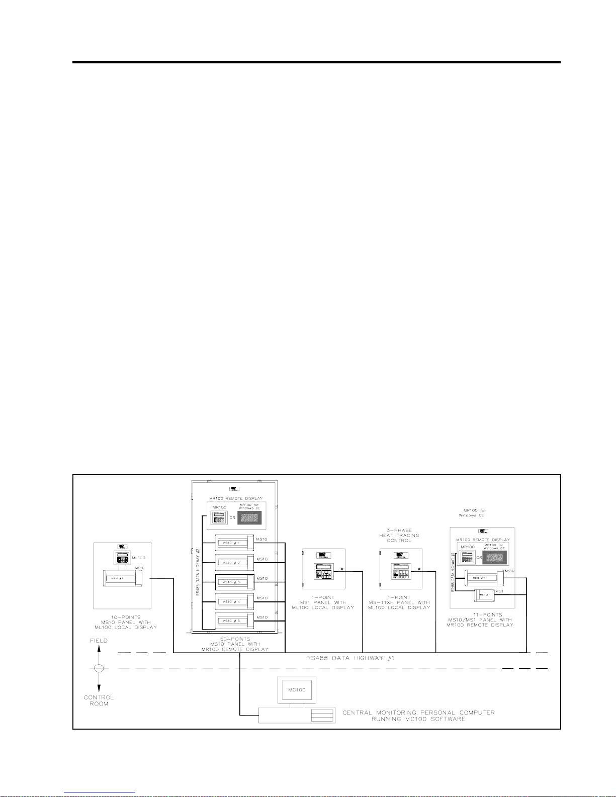
The MasterTrace™ heat tracing system is a compatible family of electronic controls that uses state of the art technology to give complete control and central monitoring of electric heat tracing systems. MasterTrace™ can be used with
MI, self-regulating and constant wattage cable. Individual
smart controls mounted near to the pipe being traced can
communicate with a single master unit to give complete system monitoring and control from a convenient location.
Continuous process and hardware monitoring with alarms
for the complete system at a central point eliminates the
need for annual maintenance checks. Overall system cost is
lower than custom panels that have far less capability due
to the many standard features incorporated into each control.
Each heater point is monitored by a control mounted near
Chapter 3
the pipe being traced. Up to 300 points can be monitored by
a single master conveniently located to allow quick system
monitoring and fault diagnosis. A second RS485 port can be
used for communication between controls and centralized
monitoring. Each local control is completely independent
and will continue to function if the master fails or if the
communication link fails. This ensures maximum reliability
and minimizes vulnerability in the event of a hardware failure. Additional points can be added at any time as easily as
a mechanical thermostat can be installed. Unlike control
schemes using programmable controllers, no software development is required. The complete system is operational
as soon as it is installed.
To ensure that the MasterTrace™ heat tracing system will
continue to meet the needs of plants as they upgrade to
fully automated operation, an additional data highway can
be implemented using the second RS485 port. By connecting controls to a programmable controller that is tied into a
central plant computer, alarms caused by heat tracing malfunctions can immediately be flagged in a central control
location. The complete system can be monitored and problem descriptions can be received for fast fault diagnosis
and repair. In addition, the setpoints of any remote control
can be altered by the master control (MR100 or MR100 for
Windows CE) or a central computer (MC100). Heaters can
be manually forced on and any pipe temperature can be
read.
Product Description
Figure 3.1 MasterTrace™ System Concept
3.1
Page 15

MASTER
TRACE Chapter 3
3.2 Features and Benefits
Product Description
Requirements
Te mperature Control
Syste m Fault Alarms
Me s sage D isplay
MasterTrace Fe ature s
0 to 500°C/32 to 932°F setpoint
Digital temperature selection from ke yboard
100 ohm platinum RTD sensor
3 wire, lead resistance compensation
Proportional control with solid-state model
User definable heater names on alarm display for fast fault location identification
Normally open/normally closed alarm contacts
Process Fault Alarms
Breaker left o ff or tripped
Low c urrent
High current alarm a nd trip
Ground fault alarm a nd trip
High t emper ature
Low temperature
Sensor open/short
System OK and alarm indicators
Hardware failure alarms
Communication errors
Self-test failure
Actual Temperature
Minimum and maximum tempe r atur e
Heater current
Ground fault c urrent
Heater power co nsumption
Operating power cost
Running ho ur s
All s e tp o ints
Earl y Warning
R emot e Moni toring
Verification
Hazardous/Ordinary Area
Mount ing
Relia bility
Low Ins ta lle d Cost
TRAC ECHECK exercises dormant systems for early warning to prevent shutdowns
Alpha-numeric display shows cause of alarm and heater location
English character/graphics display of all values
Local or remote d isplay and p rogramming
RS4 85 co mmunication to r emote monitor
Alarm contacts for PC interface or remote indicator alarm
Measured temperature displayed and easily verified in the field
Heater on indication for setpoint accuracy checking
Precision components. No mechanical parts for calibration drift
Control Modules are CSA NRTL/C approved for ordinary or Class1, Div.II, Groups
A,B,C, D or Class1 Zone 2, Gro up IIC hazardous areas
-40to+60°Coperatingrange
Solid-state relay driver output or 30A/280 VAC internal mechanical relay
Easy retrofit replacement for mechanical thermostats for system upgrading
Ca libration e as y to verify with simple to o ls in the field
Self test...hardware alarm
Self co ntained local controls c ontinue to function if master defective
Competitively priced
Compact, 10 points per MS-10 for large control panels
Add additional points easily at any time
Ground fault heater trip eliminates expensive ground fault circuit breaker
Many standard features for most applications simplifies spare parts stocking
Field programmable values easily changed
3.2
Page 16

MASTER
TRACE
3.3 Control Module Specifications
3.3.1 MS-1DIN2 Control Module
Chapter 3
Product Description
T emperature Input
Range: -50°C to +500°C
Accuracy: ±2°C
Repeatability: ±1°C
Sensor: Two 100 ohm, Platinum, 3-wire RTD
per point
20 ohm maximum lead resistance
Heater Switching
Number of Switches: One dual pole
Switch Rating: 30A @ 280Vac max
Current Measurement: 0.1 to 30A 3%±0.2A
GF Measurement: 10 to 1000mA 5% ±2mA
Voltage Measurement: 0 to 300Vac 3%±2V
Control Power
Power Requirements: 20VA @ 120Vac, 50 or 60Hz
Communications
Communication Ports: (1) Parallel Local Interface connection
(2) Serial network connections
Serial Communications
Type: RS485
Protocol: Modbus® RTU.
Transmission Rate: 600, 1200, 2400, 4800, 9600 baud.
Interconnect: 2-wire, shielded, twisted pair.
Highway Distance: 4,000 feet without repeater.
Modules per Highway: (1) Interface and (30) Control Modules.
Measured Values
Temperature: -50 to 500°C (-58 to 932°F)
Minimum Temperature: -50 to 500°C (-58 to 932°F)
Maximum Temperature: -50 to 500°C (-58 to 932°F)
Heater Current: 0.1 to 100A
Ground Fault Current: 0.01 to 1.0A
Heater Voltage: 0 to 300Vac
Heater Utilization: 0 to 100%
Power Consumption: 0 to 1,000 MWh
Operating Cost: 0 to $1,000,000.00
Environment
Approval: CSA NRTL/C for Ordinary areas
Operating Range: -40°C to +60°C
Conformal Coating: Boards conformal coated for hostile
environments
Alarm
Alarm Output: Programmable for NO or NC contacts
One DC opto-isolated contact
One dry mechanical contact
Alarm Output Rating: DC contact: 30Vdc/0.1A, 500mW max
Dry mech contact: [email protected] max
Alarm Light Output: LED Indicator: 12Vdc/30mA
Alarm Messages
Temperature: High Temperature Alarm
Low Temperature Alarm
Current: Low Current Alarm
High Current Trip
Ground Fault Current: Ground Fault Current Alarm
Ground Fault Current Trip
V oltage: Low Voltage Alarm
Hardware: Self-Check Failure
Switch Shorted
RTD Open
RTD Shorted
User-Settable Options
Heater Status: Enable or Disable
Heater Name or Tag: 16 Character Alphanumeric
Temperature Units: °C or °F
Control Strategy: On or Off
Deadband: 0 to 50C° (0-90F°)
Temperature Setpoint: 0 to 500°C (32 to 932°F)
High Temp Alarm: 0 to 500°C (32 to 932°F)
Low Temp Alarm: -50 to 500°C (-58 to 932°F)
High Current Alarm: 0.5 to 30A
Low Current Alarm: 0.5 to 30A
High Current Trip: 0.5 to 30A
Ground Fault Alarm: 0.01 to 1.0A
Ground Fault Trip: 0.01 to 1.0A
TraceCheck Interval: 1 to 24 hr.
Low Voltage Alarm: 0 to 300Vac
RTD Control Strategy: Single, Backup, Highest, Lowest,
Average or High Temperature Cutout
RTD Fail-safe: Heater On or Heater Off
Master Override Input: On or Off
Alarm Contacts: NO or NC for each contact
Alarm Light: Alarm on, Alarm off, Flash during alarm
then on, Flash during alarm then off
Specifications subject to change without notice.
3.3
Page 17

MASTER
TRACE Chapter 3
3.3.2 MS-1DXH0 Control Module
Product Description
T emperature Input
Range: -50°C to +500°C
Accuracy: ±2°C
Repeatability: ±1°C
Sensor: Two 100 ohm, Platinum, 3-wire RTD
per point
20 ohm maximum lead resistance
Current Input
Range: 0.1A to 100A
Accuracy: 3%±0.2A
Sensor: One current transformer
GF Input
Range: 10mA to 1000mA
Accuracy: 5%±2mA
Sensor: One current transformer
Voltage Input
Range: 0Vac to 300Vac
Accuracy: 3%±2V
Sensor: One voltage transformer
Heater Switching
No. of SSR Outputs: One
SSR Output Rating: 12Vdc@15mA max output for driving
external solid-state relays
600Vac@100A max.
GF CT will allow two conductors of O.D.
0.35” max.
Heater Configuration: Single Phase
Control Power
Power Requirements: 15VA @ 120Vac, 50 or 60Hz
Communications
Communication Ports: (1) Parallel Local Interface connection
(2) Serial network connections
Serial Communications
Type: RS485
Protocol: Modbus® RTU.
Transmission Rate: 1200, 2400, 4800, 9600 baud.
Interconnect: 2-wire, shielded, twisted pair.
Highway Distance: 4,000 feet without repeater.
Modules per Highway: (1) Interface and (30) Control Modules.
Measured Values
Temperature: -50 to 500°C (-58 to 932°F)
Minimum Temperature: -50 to 500°C (-58 to 932°F)
Maximum Temperature: -50 to 500°C (-58 to 932°F)
Heater Current: 0.1 to 100A
Heater Percent Power 0 to 100%
Ground Fault Current: 0.01 to 1.0A
Heater Voltage: 0 to 300Vac
Heater Utilization: 0 to 100%
Power Consumption: 0 to 1,000 MWh
Operating Cost: 0 to $1,000,000.00
Environment
Approval: CSA NRTL/C
Class1, Div.II, Groups A,B,C,D
Class1 Zone 2, Group IIC
Operating Range: -40°C to +60°C
Conformal Coating: Boards conformal coated for hostile
environments
Alarm
Alarm Output: Programmable for NO or NC contacts
One DC opto-isolated contact
One dry mechanical contact
Alarm Output Rating:
Hazardous Areas: DC contact: 30Vdc/0.1A, 500mW max
Dry mech contact: 30Vdc@10mA max
Ordinary Areas: DC contact: 30Vdc/0.1A, 500mW max
Dry mech contact: [email protected] max
Alarm Light Output: LED Indicator: 12Vdc/30mA
Alarm Messages
Temperature: High Temperature Alarm
Low Temperature Alarm
Current: High Current Alarm
Low Current Alarm
High Current Trip
Ground Fault Current: Ground Fault Current Alarm
Ground Fault Current Trip
V oltage: Low Voltage Alarm
Hardware: Self-Check Failure
Switch Shorted
RTD Open
RTD Shorted
User-Settable Options
Heater Status: Enable or Disable
Heater Name or Tag: 16 Character Alphanumeric
Temperature Units: °C or °F
Control Strategy: On-Off or Proportional
Deadband: 0 to 50C° (0-90F°)
PowerLimit: 0.5 to100A
Temperature Setpoint: 0 to 500°C (32 to 932°F)
High Temp Alarm: 0 to 500°C (32 to 932°F)
Low Temp Alarm: -50 to 500°C (-58 to 932°F)
High Current Alarm: 0.5 to 100A
Low Current Alarm: 0.5 to 100A
High Current Trip: 0.5 to 100A
Ground Fault Alarm: 0.01 to 1.0A
Ground Fault Trip: 0.01 to 1.0A
TraceCheck Interval: 1 to 24 hr.
Low Voltage Alarm: 0 to 300Vac
RTD Control Strategy: Single, Backup, Highest, Lowest,
Average or High Temperature Cutout
RTD Fail-safe: Heater On or Heater Off
Master Override Input: On or Off
Alarm Contacts: NO or NC for each contact
Alarm Light: Alarm on, Alarm off, Flash during alarm
then on, Flash during alarm then off
Specifications subject to change without notice.
3.4
Page 18

MASTER
TRACE
3.3.3 MS-1TXH0 Control Module
Chapter 3
Product Description
T emperature Input
Range: -50°C to +500°C
Accuracy: ±2°C
Repeatability: ±1°C
Sensor: Two 100 ohm, Platinum, 3-wire RTD
per point
20 ohm maximum lead resistance
Current Input
Range: 0.1A to 100A
Accuracy: 3%±0.2A
Sensor: Three current transformers
GF Input
Range: 10mA to 1000mA
Accuracy: 5%±2mA
Sensor: One current transformer
Heater Switching
No. of SSR Outputs: One
SSR Output Rating: 12Vdc@15mA max output for driving
external solid-state relays
600Vac@100A max.
GF CT will allow three conductors of
O.D 0.32” max.
Heater Configuration: Three Phase
Control Power
Power Requirements: 15VA @ 120Vac, 50 or 60Hz
Communications
Communication Ports: (1) Parallel Local Interface connection
(2) Serial network connections
Serial Communications
Type: RS485
Protocol: Modbus® RTU.
Transmission Rate: 600, 1200, 2400, 4800, 9600 baud.
Interconnect: 2-wire, shielded, twisted pair.
Highway Distance: 4,000 feet without repeater.
Modules per Highway: (1) Interface and (30) Control Modules.
Measured Values
Temperature: -50 to 500°C (-58 to 932°F)
Minimum Temperature: -50 to 500°C (-58 to 932°F)
Maximum Temperature: -50 to 500°C (-58 to 932°F)
Heater Current: 0.1 to 100A
Heater Percent Power: 0 to 100%
Ground Fault Current: 0.01 to 1.0A
Heater Utilization: 0 to 100%
Power Consumption: 0 to 1,000 MWh
Operating Cost: 0 to $1,000,000.00
Environment
Approval: CSA NRTL/C
Class1, Div.II, Groups A,B,C,D
Class1 Zone 2, Group IIC
Operating Range: -40°C to +60°C
Conformal Coating: Boards conformal coated for hostile
environments
Alarm
Alarm Output: Programmable for NO or NC contacts
One DC opto-isolated contact
One dry mechanical contact
Alarm Output Rating:
Hazardous Areas: DC contact: 30Vdc/0.1A, 500mW max
Dry mech contact: 30Vdc@10mA max
Ordinary Areas: DC contact: 30Vdc/0.1A, 500mW max
Dry mech contact: [email protected] max
Alarm Light Output: LED Indicator: 12Vdc/30mA
Alarm Messages
Temperature: High Temperature Alarm
Low Temperature Alarm
Current: High Current Alarm
Low Current Alarm
High Current Trip
Ground Fault Current: Ground Fault Current Alarm
Ground Fault Current Trip
Hardware: Self-Check Failure
Switch Shorted
RTD Open
RTD Shorted
User-Settable Options
Heater Status: Enable or Disable
Heater Name or Tag: 16 Character Alphanumeric
Temperature Units: °C or °F
Control Strategy: On-Off or Proportional
Deadband: 0 to 50C° (0-90F°)
PowerLimit: 0.5 to 100A
Temperature Setpoint: 0 to 500°C (32 to 932°F)
High Temp Alarm: 0 to 500°C (32 to 932°F)
Low Temp Alarm: -50 to 500°C (-58 to 932°F)
High Current Alarm: 0.5 to 100A
Low Current Alarm: 0.5 to 100A
High Current Trip: 0.5 to 100A
Ground Fault Alarm: 0.01 to 1.0A
Ground Fault Trip: 0.01 to 1.0A
TraceCheck Interval: 1 to 24 hr.
RTD Control Strategy: Single, Backup, Highest, Lowest,
Average or High Temperature Cutout
RTD Fail-safe: Heater On or Heater Off
Master Override Input: On or Off
Alarm Contacts: NO or NC for each contact
Alarm Light: Alarm on, Alarm off, Flash during alarm
then on, Flash during alarm then off
Specifications subject to change without notice.
3.5
Page 19

MASTER
TRACE Chapter 3
3.3.4 MS-2DIN2 Control Module
Product Description
T emperature Input
Range: -50°C to +500°C
Accuracy: ±2°C
Repeatability: ±1°C
Sensor: Two 100 ohm, Platinum, 3-wire RTD;
One per point
20 ohm maximum lead resistance
Heater Switching
Number of Switches: Two dual pole
Switch Rating: 30A @ 280Vac max
Current Measurement: 0.1 to 30A 3%±0.2A
GF Measurement: 10 to 1000mA 5%±5mA
Voltage Measurement: 0 to 300Vac 3%±2V
Control Power
Power Requirements: 15VA @ 120Vac, 50 or 60Hz
Communications
Communication Ports: (1) Parallel Local Interface connection
(2) Serial network connections
Serial Communications
Type: RS485
Protocol: Modbus® RTU.
Transmission Rate: 600, 1200, 2400, 4800, 9600 baud.
Interconnect: 2-wire, shielded, twisted pair.
Highway Distance: 4,000 feet without repeater.
Modules per Highway: (1) Interface and (30) Control Modules.
Measured Values
Temperature: -50 to 500°C (-58 to 932°F)
Minimum Temperature: -50 to 500°C (-58 to 932°F)
Maximum Temperature: -50 to 500°C (-58 to 932°F)
Heater Current: 0.1 to 100A
Ground Fault Current: 0.01 to 1.0A
Heater Voltage: 0 to 300Vac
Heater Utilization: 0 to 100%
Power Consumption: 0 to 1,000 MWh
Operating Cost: 0 to $1,000,000.00
Environment
Approval: CSA NRTL/C for Ordinary areas
Operating Range: -40°C to +60°C
Conformal Coating: Boards conformal coated for hostile
environments
Alarm
Alarm Output: Programmable for NO or NC contacts
One DC opto-isolated contact
One dry mechanical contact
Alarm Output Rating: DC contact: 30Vdc/0.1A, 500mW max
Dry mech contact: [email protected] max
Alarm Light Output: LED Indicator: 12Vdc/30mA
Alarm Messages
Temperature: High Temperature Alarm
Low Temperature Alarm
Current: High Current Alarm
Low Current Alarm
High Current Trip
Ground Fault Current: Ground Fault Current Alarm
Ground Fault Current Trip
V oltage: Low Voltage Alarm
Hardware: Self-Check Failure
Switch Shorted
RTD Open
RTD Shorted
User-Settable Options
Heater Status: Enable or Disable
Heater Name or Tag: 16 Character Alphanumeric
Temperature Units: °C or °F
Control Strategy: On-Off
Deadband: 0 to 50C° (0-90F°)
StaggerStart: On or Off
Temperature Setpoint: 0 to 500°C (32 to 932°F)
High Temp Alarm: 0 to 500°C (32 to 932°F)
Low Temp Alarm: -50 to 500°C (-58 to 932°F)
High Current Alarm: 0.5 to 30A
Low Current Alarm: 0.5 to 30A
High Current Trip: 0.5 to 30A
Ground Fault Alarm: 0.01 to 1.0A
Ground Fault Trip: 0.01 to 1.0A
TraceCheck Interval: 1 to 24 hr.
Low Voltage Alarm: 0 to 300Vac
RTD Fail-safe: Heater On or Heater Off
Master Override Input: On or Off
Alarm Contacts: NO or NC for each contact
Alarm Light: Alarm on, Alarm off, Flash during alarm
then on, Flash during alarm then off
Specifications subject to change without notice.
3.6
Page 20

MASTER
TRACE
3.3.5 MS-2DXH0 Control Module
Chapter 3
Product Description
T emperature Input
Range: -50°C to +500°C
Accuracy: ±2°C
Repeatability: ±1°C
Sensor: Two 100 ohm, Platinum, 3-wire RTD;
one per point
20 ohm maximum lead resistance
Current Input
Range: 0.1A to 100A
Accuracy: 3%±0.2A
Sensor: Two current transformers; one per point
GF Input
Range: 10mA to 1000mA
Accuracy: 5%±2mA
Sensor: Two current transformers; one per point
Voltage Input
Range: 0Vac to 300Vac
Accuracy: 3%±2V
Sensor: Two voltage transformers; one per point
Heater Switching
No. of SSR Outputs: Two
SSR Output Rating: 12Vdc@15mA max output for driving
external solid-state relays
600Vac@100A max.
GF CT will allow two conductors of O.D.
0.35” max.
Heater Configuration: Single Phase
Control Power
Power Requirements: 15VA @ 120Vac, 50 or 60Hz
Communications
Communication Ports: (1) Parallel Local Interface connection
(2) Serial network connections
Serial Communications
Type: RS485
Protocol: Modbus® RTU.
Transmission Rate: 600, 1200, 2400, 4800, 9600 baud.
Interconnect: 2-wire, shielded, twisted pair.
Highway Distance: 4,000 feet without repeater.
Modules per Highway: (1) Interface and (30) Control Modules.
Measured Values
Temperature: -50 to 500°C (-58 to 932°F)
Minimum Temperature: -50 to 500°C (-58 to 932°F)
Maximum Temperature: -50 to 500°C (-58 to 932°F)
Heater Current: 0.1 to 100A
Heater Percent Power: 0 to 100%
Ground Fault Current: 0.01 to 1.0A
Heater Voltage: 0 to 300Vac
Heater Utilization: 0 to 100%
Power Consumption: 0 to 1,000 MWh
Operating Cost: 0 to $1,000,000.00
Environment
Approval: CSA NRTL/C
Class1, Div.II, Groups A,B,C,D
Class1 Zone 2, Group IIC
Operating Range: -40°C to +60°C
Conformal Coating: Boards conformal coated for hostile
environments
Alarm
Alarm Output: Programmable for NO or NC contacts
One DC opto-isolated contact
One dry mechanical contact
Alarm Output Rating:
Hazardous Areas: DC contact: 30Vdc/0.1A, 500mW max
Dry mech contact: 30Vdc@10mA max
Ordinary Areas: DC contact: 30Vdc/0.1A, 500mW max
Dry mech contact: [email protected] max
Alarm Light Output: LED Indicator: 12Vdc/30mA
Alarm Messages
Temperature: High Temperature Alarm
Low Temperature Alarm
Current: High Current Alarm
Low Current Alarm
High Current Trip
Ground Fault Current: Ground Fault Current Alarm
Ground Fault Current Trip
V oltage: Low Voltage Alarm
Hardware: Self-Check Failure
Switch Shorted
RTD Open
RTD Shorted
User-Settable Options
Heater Status: Enable or Disable
Heater Name or Tag: 16 Character Alphanumeric
Temperature Units: °C or °F
Control Strategy: On-Off or Proportional
Deadband: 0 to 50C° (0-90F°)
StaggerStart: On or Off
PowerLimit: 0.5 to 100A
Temperature Setpoint: 0 to 500°C (32 to 932°F)
High Temp Alarm: 0 to 500°C (32 to 932°F)
Low Temp Alarm: -50 to 500°C (-58 to 932°F)
High Current Alarm: 0.5 to 100A
Low Current Alarm: 0.5 to 100A
High Current Trip: 0.5 to 100A
Ground Fault Alarm: 0.01 to 1.0A
Ground Fault Trip: 0.01 to 1.0A
TraceCheck Interval: 1 to 24 hr.
Low Voltage Alarm: 0 to 300Vac
RTD Fail-safe: Heater On or Heater Off
Master Override Input: On or Off
Alarm Contacts: NO or NC for each contact
Alarm Light: Alarm on, Alarm off, Flash during alarm
then on, Flash during alarm then off
Specifications subject to change without notice.
3.7
Page 21

MASTER
TRACE Chapter 3
3.3.6 MS-5ADIN2 Control Module
Product Description
T emperature Input
Range: -50°C to +500°C
Accuracy: ±2°C
Repeatability: ±1°C
Sensor: Ten 100 ohm, Platinum, 3-wire RTD;
two per point
20 ohm maximum lead resistance
Heater Switching
Number of Switches: Five dual pole
Switch Rating: 30A @ 280Vac max
Current Measurement: 0.1 to 30A 3%±0.2A
GF Measurement: 10 to 1000mA 5%±2mA
Ground Fault
Maximum Trip Time: 13.7 seconds
Control Power
Power Requirements: 35VA @ 120Vac, 50 or 60Hz
Communications
Communication Ports: (1) Parallel Local Interface connection
(2) Serial network connections
Serial Communications
Type: RS485
Protocol: Modbus® RTU.
Transmission Rate: 600, 1200, 2400, 4800, 9600 baud.
Interconnect: 2-wire, shielded, twisted pair.
Highway Distance: 4,000 feet without repeater.
Modules per Highway: (1) Interface and (30) Control Modules.
Measured Values
Temperature: -50 to 500°C (-58 to 932°F)
Minimum Temperature: -50 to 500°C (-58 to 932°F)
Maximum Temperature: -50 to 500°C (-58 to 932°F)
Heater Current: 0.1 to 100A
Ground Fault Current: 0.01 to 1.0A
Heater Utilization: 0 to 100%
Power Consumption: 0 to 1,000 MWh
Operating Cost: 0 to $1,000,000.00
Environment
Approval: CSA NRTL/C for Ordinary areas
Operating Range: -40°C to +60°C
Conformal Coating: Boards conformal coated for hostile
environments
Alarm
Alarm Output: Programmable for NO or NC contacts
One DC opto-isolated contact
One dry mechanical contact
Alarm Output Rating: DC contact: 30Vdc/0.1A, 500mW max
Dry mech contact: 120Vac/1.0A max
30Vdc/0.1A max
Alarm Light Output: LED Indicator: 12Vdc/30mA
Alarm Messages
Temperature: High Temperature Alarm
Low Temperature Alarm
Current: High Current Alarm
Low Current Alarm
High Current Trip
Ground Fault Current: Ground Fault Current Alarm
Ground Fault Current Trip
Hardware: Self-Check Failure
Switch Shorted
RTD Open
RTD Shorted
User-Settable Options
Heater Status: Enable or Disable
Heater Name or Tag: 16 Character Alphanumeric
Temperature Units: °C or °F
Control Strategy: On-Off
Deadband: 0 to 50C° (0-90F°)
StaggerStart: On or Off
Temperature Setpoint: 0 to 500°C (32 to 932°F)
High Temp Alarm: 0 to 500°C (32 to 932°F)
Low Temp Alarm: -50 to 500°C (-58 to 932°F)
High Current Alarm: 0.5 to 30A
Low Current Alarm: 0.5 to 30A
High Current Trip: 0.5 to 30A
Ground Fault Alarm: 0.01 to 1.0A
Ground Fault Trip: 0.01 to 1.0A
TraceCheck Interval: 1 to 24 hr.
RTD Control Strategy: Single, Backup, Highest, Lowest,
Average or High Temperature Cutout
RTD Fail-safe: Heater On or Heater Off
Master Override Input: On or Off
Alarm Contacts: NO or NC for each contact
Alarm Light: Alarm on, Alarm off, Flash during alarm
then on, Flash during alarm then off
GF Test: 1 to 24hrs, test now
Specifications subject to change without notice.
3.8
Page 22

MASTER
TRACE
3.3.7 MS-5ADXH0 Control Module
Chapter 3
Product Description
T emperature Input
Range: -50°C to +500°C
Accuracy: ±2°C
Repeatability: ±1°C
Sensor: Ten 100 ohm, Platinum, 3-wire RTD;
two per point
20 ohm maximum lead resistance
Current Input
Range: 0.1A to 100A
Accuracy: 3%±0.2A
Sensor: Five current transformers; one per point
GF Input
Range: 10mA to 1000mA
Accuracy: 5%±2mA
Sensor: Five current transformers; one per point
Maximum Trip Time: 14.1 seconds
Heater Switching
No. of SSR Outputs: Five
SSR Output Rating: 12Vdc@15mA max output for driving
external solid-state relays
600Vac@100A max.
GF CT will allow two conductors of O.D.
0.35” max.
Heater Configuration: Single Phase
Control Power
Power Requirements: 15VA @ 120Vac, 50 or 60Hz
Communications
Communication Ports: (1) Parallel Local Interface connection
(2) Serial network connections
Serial Communications
Type: RS485
Protocol: Modbus® RTU.
Transmission Rate: 600, 1200, 2400, 4800, 9600 baud.
Interconnect: 2-wire, shielded, twisted pair.
Highway Distance: 4,000 feet without repeater.
Modules per Highway: (1) Interface and (30) Control Modules.
Measured Values
Temperature: -50 to 500°C (-58 to 932°F)
Minimum Temperature: -50 to 500°C (-58 to 932°F)
Maximum Temperature: -50 to 500°C (-58 to 932°F)
Heater Current: 0.1 to 100A
Heater Percent Power: 0 to 100%
Ground Fault Current: 0.01 to 1.0A
Heater Utilization: 0 to 100%
Power Consumption: 0 to 1,000 MWh
Operating Cost: 0 to $1,000,000.00
Environment
Approval: CSA NRTL/C
Class1, Div.II, Groups A,B,C,D
Class1 Zone 2, Group IIC
Operating Range: -40°C to +60°C
Conformal Coating: Boards conformal coated for hostile
environments
Alarm
Alarm Output: Programmable for NO or NC contacts
One DC opto-isolated contact
One dry mechanical contact
Alarm Output Rating:
Hazardous Areas: DC contact: 30Vdc/0.1A, 500mW max
Dry mech contact: 30Vdc/10mA max
250Vac/0.5A max
(not subject to a corrosive environment)
Ordinary Areas: DC contact: 30Vdc/0.1A, 500mW max
Dry mech contact: 120Vac/1.0A max
30Vdc/0.1A max
Alarm Light Output: LED Indicator: 12Vdc/30mA
Alarm Messages
Temperature: High Temperature Alarm
Low Temperature Alarm
Current: High Current Alarm
Low Current Alarm
High Current Trip
Ground Fault Current: Ground Fault Current Alarm
Ground Fault Current Trip
Hardware: Self-Check Failure
Switch Shorted
RTD Open
RTD Shorted
User-Settable Options
Heater Status: Enable or Disable
Heater Name or Tag: 16 Character Alphanumeric
Temperature Units: °C or °F
Control Strategy: On-Off or Proportional
Deadband: 0 to 50C° (0-90F°)
StaggerStart: On or Off
PowerLimit: 0.5 to 100A
Temperature Setpoint: 0 to 500°C (32 to 932°F)
High Temp Alarm: 0 to 500°C (32 to 932°F)
Low Temp Alarm: -50 to 500°C (-58 to 932°F)
High Current Alarm: 0.5 to 100A
Low Current Alarm: 0.5 to 100A
High Current Trip: 0.5 to 100A
Ground Fault Alarm: 0.01 to 1.0A
Ground Fault Trip: 0.01 to 1.0A
TraceCheck Interval: 1 to 24 hr.
RTD Control Strategy: Single, Backup, Highest, Lowest,
Average or High Temperature Cutout
RTD Fail-safe: Heater On or Heater Off
Master Override Input: On or Off
Alarm Contacts: NO or NC for each contact
Alarm Light: Alarm on, Alarm off, Flash during alarm
then on, Flash during alarm then off
GF Test: 1 to 24hrs, test now
Specifications subject to change without notice.
3.9
Page 23

MASTER
TRACE Chapter 3
3.3.8 MS-5A TXH0 Control Module
Product Description
T emperature Input
Range: -50°C to +500°C
Accuracy: ±2°C
Repeatability: ±1°C
Sensor: Ten 100 ohm, Platinum, 3-wire RTD;
two per point
20 ohm maximum lead resistance
Current Input
Range: 0.1A to 100A
Accuracy: 3%±0.2A
Sensor: Fifteen current transformers; three per
point
GF Input
Range: 10mA to 1000mA
Accuracy: 5%±2mA
Sensor: Five current transformers; one per point
Maximum Trip Time: 18.2 seconds
Heater Switching
No. of SSR Outputs: Five
SSR Output Rating: 12Vdc@15mA max output for driving
external solid-state relays
600Vac@100A max.
GF CT will allow three conductors of
O.D. 0.32” max.
Heater Configuration: Three Phase
Control Power
Power Requirements: 15VA @ 120Vac, 50 or 60Hz
Communications
Communication Ports: (1) Parallel Local Interface connection
(2) Serial network connections
Serial Communications
Type: RS485
Protocol: Modbus® RTU.
Transmission Rate: 600, 1200, 2400, 4800, 9600 baud.
Interconnect: 2-wire, shielded, twisted pair.
Highway Distance: 4,000 feet without repeater.
Modules per Highway: (1) Interface and (30) Control Modules.
Measured Values
Temperature: -50 to 500°C (-58 to 932°F)
Minimum Temperature: -50 to 500°C (-58 to 932°F)
Maximum Temperature: -50 to 500°C (-58 to 932°F)
Heater Current: 0.1 to 100A
Heater Percent Power: 0 to 100%
Ground Fault Current: 0.01 to 1.0A
Heater Utilization: 0 to 100%
Power Consumption: 0 to 1,000 MWh
Operating Cost: 0 to $1,000,000.00
Environment
Approval: CSA NRTL/C
Class1, Div.II, Groups A,B,C,D
Class1 Zone 2, Group IIC
Operating Range: -40°C to +60°C
Conformal Coating: Boards conformal coated for hostile
environments
Alarm
Alarm Output: Programmable for NO or NC contacts
One DC opto-isolated contact
One dry mechanical contact
Alarm Output Rating:
Hazardous Areas: DC contact: 30Vdc/0.1A, 500mW max
Dry mech contact: 30Vdc/10mA max
250Vac/0.5A max
(not subject to a corrosive environment)
Ordinary Areas: DC contact: 30Vdc/0.1A, 500mW max
Dry mech contact: 120Vac/1.0A max
30Vdc/0.1A max
Alarm Light Output: LED Indicator: 12Vdc/30mA
Alarm Messages
Temperature: High Temperature Alarm
Low Temperature Alarm
Current: High Current Alarm
Low Current Alarm
High Current Trip
Ground Fault Current: Ground Fault Current Alarm
Ground Fault Current Trip
Hardware: Self-Check Failure
Switch Shorted
RTD Open
RTD Shorted
User-Settable Options
Heater Status: Enable or Disable
Heater Name or Tag: 16 Character Alphanumeric
Temperature Units: °C or °F
Control Strategy: On-Off or Proportional
Deadband: 0 to 50C° (0-90F°)
StaggerStart: On or Off
PowerLimit: 0.5 to 100A
Temperature Setpoint: 0 to 500°C (32 to 932°F)
High Temp Alarm: 0 to 500°C (32 to 932°F)
Low Temp Alarm: -50 to 500°C (-58 to 932°F)
High Current Alarm: 0.5 to 100A
Low Current Alarm: 0.5 to 100A
High Current Trip: 0.5 to 100A
Ground Fault Alarm: 0.01 to 1.0A
Ground Fault Trip: 0.01 to 1.0A
TraceCheck Interval: 1 to 24 hr.
RTD Control Strategy: Single, Backup, Highest, Lowest,
Average or High Temperature Cutout
RTD Fail-safe: Heater On or Heater Off
Master Override Input: On or Off
Alarm Contacts: NO or NC for each contact
Alarm Light: Alarm on, Alarm off, Flash during alarm
then on, Flash during alarm then off
GF Test: 1 to 24hrs, test now
Specifications subject to change without notice.
3.10
Page 24

MASTER
TRACE
3.3.9 MS-10ADIN2
Chapter 3
Product Description
T emperature Input
Range: -50°C to +500°C
Accuracy: ±2°C
Repeatability: ±1°C
Sensor: Ten 100 ohm, Platinum, 3-wire RTD;
one per point
20 ohm maximum lead resistance
Heater Switching
Number of Switches: Ten dual pole
Switch Rating: 30A @ 280Vac max
Current Measurement: 0.1 to 30A 3%±0.2A
GF Measurement: 10 to 1000mA 5%±2mA
Control Power
Power Requirements: 50VA @ 120Vac, 50 or 60Hz
Communications
Communication Ports: (1) Parallel Local Interface connection
(2) Serial network connections
Serial Communications
Type: RS485
Protocol: Modbus® RTU.
Transmission Rate: 600, 1200, 2400, 4800, 9600 baud.
Interconnect: 2-wire, shielded, twisted pair.
Highway Distance: 4,000 feet without repeater.
Modules per Highway: (1) Interface and (30) Control Modules.
Measured Values
Temperature: -50 to 500°C (-58 to 932°F)
Minimum Temperature: -50 to 500°C (-58 to 932°F)
Maximum Temperature: -50 to 500°C (-58 to 932°F)
Heater Current: 0.1 to 100A
Ground Fault Current: 0.01 to 1.0A
Power Consumption: 0 to 1,000 MWh
Heater Utilization: 0 to 100%
Operating Cost: 0 to $1,000,000.00
Ground Fault
Maximum Trip Time: 24.5 seconds
Environment
Approval: CSA NRTL/C for Ordinary areas
Operating Range: -40°C to +60°C
Conformal Coating: Boards conformal coated for hostile
environments
Alarm
Alarm Output: Programmable for NO or NC contacts
One DC opto-isolated contact
One dry mechanical contact
Alarm Output Rating: DC contact: 30Vdc/0.1A, 500mW max
Dry mech contact: 120Vac/1.0A max
30Vdc/0.1A max
Alarm Light Output: LED Indicator: 12Vdc/30mA
Alarm Messages
Temperature: High Temperature Alarm
Low Temperature Alarm
Current: High Current Alarm
Low Current Alarm
High Current Trip
Ground Fault Current: Ground Fault Current Alarm
Ground Fault Current Trip
Hardware: Self-Check Failure
Switch Shorted
RTD Open
RTD Shorted
User-Settable Options
Heater Status: Enable or Disable
Heater Name or Tag: 16 Character Alphanumeric
Temperature Units: °C or °F
Control Strategy: On-Off
Deadband: 0 to 50C° (0-90F°)
StaggerStart: On or Off
Temperature Setpoint: 0 to 500°C (32 to 932°F)
High Temp Alarm: 0 to 500°C (32 to 932°F)
Low Temp Alarm: -50 to 500°C (-58 to 932°F)
High Current Alarm: 0.5 to 30A
Low Current Alarm: 0.5 to 30A
High Current Trip: 0.5 to 30A
Ground Fault Alarm: 0.01 to 1.0A
Ground Fault Trip: 0.01 to 1.0A
TraceCheck Interval: 1 to 24 hr.
RTD Fail-safe: Heater On or Heater Off
Master Override Input: On or Off
Alarm Contacts: NO or NC for each contact
Alarm Light: Alarm on, Alarm off, Flash during alarm
then on, Flash during alarm then off
GF Test: 1 to 24hrs, test now
Specifications subject to change without notice.
3.11
Page 25

MASTER
TRACE Chapter 3
Product Description
3.3.10 MS-10ADIN2R
T emperature Input
Range: -50°C to +500°C
Accuracy: ±2°C
Repeatability: ±1°C
Sensor: Twenty 100 ohm, Platinum, 3-wire
RTD; two per point
20 ohm maximum lead resistance
Heater Switching
Number of Switches: Ten dual pole
Switch Rating: 30A @ 280Vac max
Current Measurement: 0.1 to 30A 3%±0.2A
GF Measurement: 10 to 1000mA 5%±2mA
Control Power
Power Requirements: 50VA @ 120Vac, 50 or 60Hz
Communications
Communication Ports: (1) Parallel Local Interface connection
(2) Serial network connections
Serial Communications
Type: RS485
Protocol: Modbus® RTU.
Transmission Rate: 600, 1200, 2400, 4800, 9600 baud.
Interconnect: 2-wire, shielded, twisted pair.
Highway Distance: 4,000 feet without repeater.
Modules per Highway: (1) Interface and (30) Control Modules.
Measured Values
Temperature: -50 to 500°C (-58 to 932°F)
Minimum Temperature: -50 to 500°C (-58 to 932°F)
Maximum Temperature: -50 to 500°C (-58 to 932°F)
Heater Current: 0.1 to 100A
Ground Fault Current: 0.01 to 1.0A
Power Consumption: 0 to 1,000 MWh
Heater Utilization: 0 to 100%
Operating Cost: 0 to $1,000,000.00
Ground Fault
Maximum Trip Time: 24.5 seconds
Environment
Approval: CSA NRTL/C for Ordinary areas
Operating Range: -40°C to +60°C
Conformal Coating: Boards conformal coated for hostile
environments
Alarm
Alarm Output: Programmable for NO or NC contacts
One DC opto-isolated contact
One dry mechanical contact
Alarm Output Rating: DC contact: 30Vdc/0.1A, 500mW max
Dry mech contact: 120Vac/1.0A max
30Vdc/0.1A max
Alarm Light Output: LED Indicator: 12Vdc/30mA
Alarm Messages
Temperature: High Temperature Alarm
Low Temperature Alarm
Current: High Current Alarm
Low Current Alarm
High Current Trip
Ground Fault Current: Ground Fault Current Alarm
Ground Fault Current Trip
Hardware: Self-Check Failure
Switch Shorted
RTD Open
RTD Shorted
User-Settable Options
Heater Status: Enable or Disable
Heater Name or Tag: 16 Character Alphanumeric
Temperature Units: °C or °F
Control Strategy: On-Off
Deadband: 0 to 50C° (0-90F°)
StaggerStart: On or Off
Temperature Setpoint: 0 to 500°C (32 to 932°F)
High Temp Alarm: 0 to 500°C (32 to 932°F)
Low Temp Alarm: -50 to 500°C (-58 to 932°F)
High Current Alarm: 0.5 to 30A
Low Current Alarm: 0.5 to 30A
High Current Trip: 0.5 to 30A
Ground Fault Alarm: 0.01 to 1.0A
Ground Fault Trip: 0.01 to 1.0A
TraceCheck Interval: 1 to 24 hr.
RTD Fail-safe: Heater On or Heater Off
Master Override Input: On or Off
Alarm Contacts: NO or NC for each contact
Alarm Light: Alarm on, Alarm off, Flash during alarm
then on, Flash during alarm then off
GF Test: 1 to 24hrs, test now
Specifications subject to change without notice.
3.12
Page 26

MASTER
TRACE
3.3.11 MS-10ADIN2T
Chapter 3
Product Description
T emperature Input
Range: -50°C to +300°C
Accuracy: ±3°C
Repeatability: ±2°C
Sensor: Thermocouple, Type K, J, T;
one per point
Heater Switching
Number of Switches: Ten dual pole
Switch Rating: 30A @ 280Vac max
Current Measurement: 0.1 to 30A 3%±0.2A
GF Measurement: 10 to 1000mA 5%±2mA
Control Power
Power Requirements: 50VA @ 120Vac, 50 or 60Hz
Communications
Communication Ports: (1) Parallel Local Interface connection
(2) Serial network connections
Serial Communications
Type: RS485
Protocol: Modbus® RTU.
Transmission Rate: 600, 1200, 2400, 4800, 9600 baud.
Interconnect: 2-wire, shielded, twisted pair.
Highway Distance: 4,000 feet without repeater.
Modules per Highway: (1) Interface and (30) Control Modules.
Measured Values
Temperature: -50 to 300°C (-58 to 572°F)
Minimum Temperature: -50 to 300°C (-58 to 572°F)
Maximum Temperature: -50 to 300°C (-58 to 572°F)
Heater Current: 0.1 to 100A
Ground Fault Current: 0.01 to 1.0A
Power Consumption: 0 to 1,000 MWh
Heater Utilization: 0 to 100%
Operating Cost: 0 to $1,000,000.00
Ground Fault
Maximum Trip Time: 24.5 seconds
Environment
Approval: CSA NRTL/C for Ordinary areas
Operating Range: -40°C to +60°C
Conformal Coating: Boards conformal coated for hostile
environments
Alarm
Alarm Output: Programmable for NO or NC contacts
One DC opto-isolated contact
One dry mechanical contact
Alarm Output Rating: DC contact: 30Vdc/0.1A, 500mW max
Dry mech contact: 120Vac/1.0A max
30Vdc/0.1A max
Alarm Light Output: LED Indicator: 12Vdc/30mA
Alarm Messages
Temperature: High Temperature Alarm
Low Temperature Alarm
Current: High Current Alarm
Low Current Alarm
High Current Trip
Ground Fault Current: Ground Fault Current Alarm
Ground Fault Current Trip
Hardware: Self-Check Failure
Switch Shorted
Thermocouple Open
User-Settable Options
Heater Status: Enable or Disable
Heater Name or Tag: 16 Character Alphanumeric
Temperature Units: °C or °F
Control Strategy: On-Off
Deadband: 0 to 50C° (0-90F°)
StaggerStart: On or Off
Temperature Setpoint: 0 to 300°C (32 to 572°F)
High Temp Alarm: 0 to 300°C (32 to 572°F)
Low Temp Alarm: -50 to 300°C (-58 to 572°F)
High Current Alarm: 0.5 to 30A
Low Current Alarm: 0.5 to 30A
High Current Trip: 0.5 to 30A
Ground Fault Alarm: 0.01 to 1.0A
Ground Fault Trip: 0.01 to 1.0A
TraceCheck Interval: 1 to 24 hr.
RTD Fail-safe: Heater On or Heater Off
Master Override Input: On or Off
Alarm Contacts: NO or NC for each contact
Alarm Light: Alarm on, Alarm off, Flash during alarm
then on, Flash during alarm then off
GF Test: 1 to 24hrs, test now
Specifications subject to change without notice.
3.13
Page 27

MASTER
TRACE Chapter 3
3.3.12 MS-10ADIN2X
Product Description
T emperature Input
Range: -50°C to +500°C
Accuracy: ±2.5°C
Repeatability: ±1°C
Sensor: Ten Xmitter Input terminals to be
connected to ten 4-20mA RTD Transmitters, one per point, for temperature
measurement;
Ten 100 ohm, Platinum, 3-wire RTDs to
be locally wired to RTD transmitters,
one per point;
18 AWG wires to connect control
module and RTD Transmitter, up to
7km apart
Heater Switching
Number of Switches: Ten dual pole
Switch Rating: 30A @ 280Vac max
Current Measurement: 0.1 to 30A 3%±0.2A
GF Measurement: 10 to 1000mA 5%±2mA
Control Power
Power Requirements: 50VA @ 120Vac, 50 or 60Hz
Communications
Communication Ports: (1) Parallel Local Interface connection
(2) Serial network connections
Serial Communications
Type: RS485
Protocol: Modbus® RTU.
Transmission Rate: 600, 1200, 2400, 4800, 9600 baud.
Interconnect: 2-wire, shielded, twisted pair.
Highway Distance: 4,000 feet without repeater.
Modules per Highway: (1) Interface and (30) Control Modules.
Measured Values
Temperature: -50 to 500°C (-58 to 932°F)
Minimum Temperature: -50 to 500°C (-58 to 932°F)
Maximum Temperature: -50 to 500°C (-58 to 932°F)
Heater Current: 0.1 to 100A
Ground Fault Current: 0.01 to 1.0A
Power Consumption: 0 to 1,000 MWh
Heater Utilization: 0 to 100%
Operating Cost: 0 to $1,000,000.00
Ground Fault
Maximum Trip Time: 24.5 seconds
Alarm
Alarm Output: Programmable for NO or NC contacts
One DC opto-isolated contact
One dry mechanical contact
Alarm Output Rating: DC contact: 30Vdc/0.1A, 500mW max
Dry mech contact: 120Vac/1.0A max
30Vdc/0.1A max
Alarm Light Output: LED Indicator: 12Vdc/30mA
Alarm Messages
Temperature: High Temperature Alarm
Low Temperature Alarm
Current: High Current Alarm
Low Current Alarm
High Current Trip
Ground Fault Current: Ground Fault Current Alarm
Ground Fault Current Trip
Hardware: Self-Check Failure
Switch Shorted
RTD Open
RTD Shorted
User-Settable Options
Heater Status: Enable or Disable
Heater Name or Tag: 16 Character Alphanumeric
Temperature Units: °C or °F
Control Strategy: On-Off
Deadband: 0 to 50C° (0-90F°)
StaggerStart: On or Off
Temperature Setpoint: 0 to 500°C (32 to 932°F)
High Temp Alarm: 0 to 500°C (32 to 932°F)
Low Temp Alarm: -50 to 500°C (-58 to 932°F)
High Current Alarm: 0.5 to 30A
Low Current Alarm: 0.5 to 30A
High Current Trip: 0.5 to 30A
Ground Fault Alarm: 0.01 to 1.0A
Ground Fault Trip: 0.01 to 1.0A
TraceCheck Interval: 1 to 24 hr.
RTD Fail-safe: Heater On or Heater Off
Master Override Input: On or Off
Alarm Contacts: NO or NC for each contact
Alarm Light: Alarm on, Alarm off, Flash during alarm
then on, Flash during alarm then off
GF Test: 1 to 24hrs, test now
Environment
Approval: CSA NRTL/C for Ordinary areas
Operating Range: -40°C to +60°C
Conformal Coating: Boards conformal coated for hostile
environments
Specifications subject to change without notice.
3.14
Page 28

MASTER
TRACE
3.3.13 MS-10ADXH0 Control Module
Chapter 3
Product Description
T emperature Input
Range: -50°C to +500°C
Accuracy: ±2°C
Repeatability: ±1°C
Sensor: Ten 100 ohm, Platinum, 3-wire RTD;
one per point
20 ohm maximum lead resistance
Current Input
Range: 0.1A to 100A
Accuracy: 3%±0.2A
Sensor: Ten current transformers; one per point
GF Input
Range: 10mA to 1000mA
Accuracy: 5%±2mA
Sensor: Ten current transformers; one per point
Maimum Trip Time: 13.7 seconds
Heater Switching
No. of SSR Outputs: Te n
SSR Output Rating: 12Vdc@15mA max output for driving
external solid-state relays
600Vac@100A max.
GF CT will allow two conductors of O.D.
0.35” max.
Heater Configuration: Single Phase
Control Power
Power Requirements: 15VA @ 120Vac, 50 or 60Hz
Communications
Communication Ports: (1) Parallel Local Interface connection
(2) Serial network connections
Serial Communications
Type: RS485
Protocol: Modbus® RTU.
Transmission Rate: 600, 1200, 2400, 4800, 9600 baud.
Interconnect: 2-wire, shielded, twisted pair.
Highway Distance: 4,000 feet without repeater.
Modules per Highway: (1) Interface and (30) Control Modules.
Measured Values
Temperature: -50 to 500°C (-58 to 932°F)
Minimum Temperature: -50 to 500°C (-58 to 932°F)
Maximum Temperature: -50 to 500°C (-58 to 932°F)
Heater Current: 0.1 to 100A
Heater Percent Power: 0 to 100%
Ground Fault Current: 0.01 to 1.0A
Heater Utilization: 0 to 100%
Power Consumption: 0 to 1,000 MWh
Operating Cost: 0 to $1,000,000.00
Environment
Approval: CSA NRTL/C
Class1, Div.II, Groups A,B,C,D
Class1 Zone 2, Group IIC
Operating Range: -40°C to +60°C
Conformal Coating: Boards conformal coated for hostile
environments
Alarm
Alarm Output: Programmable for NO or NC contacts
One DC opto-isolated contact
One dry mechanical contact
Alarm Output Rating:
Hazardous Areas: DC contact: 30Vdc/0.1A, 500mW max
Dry mech contact: 30Vdc/10mA max
250Vac/0.5A max
(not subject to a corrosive environment)
Ordinary Areas: DC contact: 30Vdc/0.1A, 500mW max
Dry mech contact: 120Vac/1.0A max
30Vdc/0.1A max
Alarm Light Output: LED Indicator: 12Vdc/30mA
Alarm Messages
Temperature: High Temperature Alarm
Low Temperature Alarm
Current: High Current Alarm
Low Current Alarm
High Current Trip
Ground Fault Current: Ground Fault Current Alarm
Ground Fault Current Trip
Hardware: Self-Check Failure
Switch Shorted
RTD Open
RTD Shorted
User-Settable Options
Heater Status: Enable or Disable
Heater Name or Tag: 16 Character Alphanumeric
Temperature Units: °C or °F
Control Strategy: On-Off or Proportional
Deadband: 0 to 50C° (0-90F°)
StaggerStart: On or Off
PowerLimit: 0.5 to 100A
Temperature Setpoint: 0 to 500°C (32 to 932°F)
High Temp Alarm: 0 to 500°C (32 to 932°F)
Low Temp Alarm: -50 to 500°C (-58 to 932°F)
High Current Alarm: 0.5 to 100A
Low Current Alarm: 0.5 to 100A
High Current Trip: 0.5 to 100A
Ground Fault Alarm: 0.01 to 1.0A
Ground Fault Trip: 0.01 to 1.0A
TraceCheck Interval: 1 to 24 hr.
RTD Fail-safe: Heater On or Heater Off
Master Override Input: On or Off
Alarm Contacts: NO or NC for each contact
Alarm Light: Alarm on, Alarm off, Flash during alarm
then on, Flash during alarm then off
GF Test: 1 to 24hrs, test now
Specifications subject to change without notice.
3.15
Page 29

MASTER
TRACE Chapter 3
Product Description
3.3.14 MS-10ADXH0R Control Module
T emperature Input
Range: -50°C to +500°C
Accuracy: ±2°C
Repeatability: ±1°C
Sensor: Twenty 100 ohm, Platinum, 3-wire
RTD; two per point
20 ohm maximum lead resistance
Current Input
Range: 0.1A to 100A
Accuracy: 3%±0.2A
Sensor: Ten current transformers; one per point
GF Input
Range: 10mA to 1000mA
Accuracy: 5%±2mA
Sensor: Ten current transformers; one per point
Maimum Trip Time: 13.7 seconds
Heater Switching
No. of SSR Outputs: Te n
SSR Output Rating: 12Vdc@15mA max output for driving
external solid-state relays
600Vac@100A max.
GF CT will allow two conductors of O.D.
0.35” max.
Heater Configuration: Single Phase
Control Power
Power Requirements: 15VA @ 120Vac, 50 or 60Hz
Communications
Communication Ports: (1) Parallel Local Interface connection
(2) Serial network connections
Serial Communications
Type: RS485
Protocol: Modbus® RTU.
Transmission Rate: 600, 1200, 2400, 4800, 9600 baud.
Interconnect: 2-wire, shielded, twisted pair.
Highway Distance: 4,000 feet without repeater.
Modules per Highway: (1) Interface and (30) Control Modules.
Measured Values
Temperature: -50 to 500°C (-58 to 932°F)
Minimum Temperature: -50 to 500°C (-58 to 932°F)
Maximum Temperature: -50 to 500°C (-58 to 932°F)
Heater Current: 0.1 to 100A
Heater Percent Power: 0 to 100%
Ground Fault Current: 0.01 to 1.0A
Heater Utilization: 0 to 100%
Power Consumption: 0 to 1,000 MWh
Operating Cost: 0 to $1,000,000.00
Environment
Approval: CSA NRTL/C
Class1, Div.II, Groups A,B,C,D
Class1 Zone 2, Group IIC
Operating Range: -40°C to +60°C
Conformal Coating: Boards conformal coated for hostile
environments
Alarm
Alarm Output: Programmable for NO or NC contacts
One DC opto-isolated contact
One dry mechanical contact
Alarm Output Rating:
Hazardous Areas: DC contact: 30Vdc/0.1A, 500mW max
Dry mech contact: 30Vdc/10mA max
250Vac/0.5A max
(not subject to a corrosive environment)
Ordinary Areas: DC contact: 30Vdc/0.1A, 500mW max
Dry mech contact: 120Vac/1.0A max
30Vdc/0.1A max
Alarm Light Output: LED Indicator: 12Vdc/30mA
Alarm Messages
Temperature: High Temperature Alarm
Low Temperature Alarm
Current: High Current Alarm
Low Current Alarm
High Current Trip
Ground Fault Current: Ground Fault Current Alarm
Ground Fault Current Trip
Hardware: Self-Check Failure
Switch Shorted
RTD Open
RTD Shorted
User-Settable Options
Heater Status: Enable or Disable
Heater Name or Tag: 16 Character Alphanumeric
Temperature Units: °C or °F
Control Strategy: On-Off or Proportional
Deadband: 0 to 50C° (0-90F°)
StaggerStart: On or Off
PowerLimit: 0.5 to 100A
Temperature Setpoint: 0 to 500°C (32 to 932°F)
High Temp Alarm: 0 to 500°C (32 to 932°F)
Low Temp Alarm: -50 to 500°C (-58 to 932°F)
High Current Alarm: 0.5 to 100A
Low Current Alarm: 0.5 to 100A
High Current Trip: 0.5 to 100A
Ground Fault Alarm: 0.01 to 1.0A
Ground Fault Trip: 0.01 to 1.0A
TraceCheck Interval: 1 to 24 hr.
RTD Fail-safe: Heater On or Heater Off
Master Override Input: On or Off
Alarm Contacts: NO or NC for each contact
Alarm Light: Alarm on, Alarm off, Flash during alarm
then on, Flash during alarm then off
GF Test: 1 to 24hrs, test now
Specifications subject to change without notice.
3.16
Page 30

MASTER
TRACE
Chapter 3
Product Description
3.3.15 ML100 Dedicated Interface Module
Control Power
Power Requirements: From Control Module ML100 Interface
connector: +5Vdc/0.1A, +8Vdc/0.4A,
-6.5Vdc/1mA
Communications
Port: 1 Dedicated parallel connection
Interconnect: 26-pin IDC ribbon cable
Cable Length: 3 feet maximum
Environment
Approval: CSA NRTL/C
Class 1, Div.II, Groups A,B,C,D
Class 1, Zone-2, Groups IIC
Operating Range: -40°C to +60°C
(LCD Display: -20°C to +60°C)
(VFD Display: -40°C to +60°C)
Conformal Coating: Boards conformal coated for hostile
environments
User Interface
Display: 16-character x 2-line LCD or VFD
Alpha-numeric display
Keypad: 9 tactile keys, polyester faceplate
- Setpoint, measured, status
- Message Up, Message Down
- Value Up, Value Down
- Reset
- Store
Contrast: Adjustable by potentiometer
Panel Indicators: Power on
Current heater display on
Serial communication active
System alarm
Process alarm
Bezel
Material: 304 Stainless steel
Mounting: For mounting on NEMA-12 or NEMA-4
enclosure door. Includes gasketing.
Optional: 304 Stainless steel shroud with plexi-
glass hinged cover to protect keypad
from physical damage.
3.3.16 MR100 Group Interface Module
Control Power
Power Requirements: 12VA @ 120Vac, 50 or 60Hz
Communications
Ports: 1 Serial network connections
Type: RS485
Protocol: Modbus® RTU.
Transmission Rate: 600, 1200, 2400, 4800, 9600 baud.
Interconnect: 2-wire, shielded, twisted pair.
Highway Distance: 4,000 feet without repeater.
Modules per Highway: (1) MR100 and (30) Control Modules.
Environment
Approval: CSA NRTL/C
Class1, Div.II, Groups A,B,C,D
Class1 Zone 2, Group IIC
Operating Range: -40°C to +60°C
(LCD Display: -20°C to +60°C)
(VFD Display: -40°C to +60°C)
Conformal Coating: Boards conformal coated for hostile
environments
Alarm
Alarm Output: Programmable for NO or NC contacts
One DC opto-isolated contact
One dry mechanical contact
Alarm Output Rating:
Hazardous Areas: DC contact: 30Vdc/0.1A, 500mW max
Dry mech contact: 30Vdc/10mA max
250Vac/0.5A max
(not subject to a corrosive environment)
Ordinary Areas: DC contact: 30Vdc/0.1A, 500mW max
Dry mech contact: 120Vac/1.0A max
30Vdc/0.1A max
Alarm Light Output: LED Indicator: 12Vdc/30mA
Alarm Messages: Refer to Control Module Specifications
User Interface
Display: 16-character x 2-line LCD or VFD
Alpha-numeric display
Keypad: 9 tactile keys, polyester faceplate
- Setpoint, measured, status
- Message Up, Message Down
- Value Up, Value Down
- Reset
- Store
Contrast: Adjustable by potentiometer
Panel Indicators: Power on
Current heater display on
Serial communication active
System alarm
Process alarm
Specifications subject to change without notice.
Bezel
Material: 304 Stainless steel
Mounting: For mounting on NEMA-4/4X
enclosure door. Includes gasketing.
Optional: 304 Stainless steel shroud with plexi-
glass hinged cover to protect keypad
from physical damage.
3.17
Page 31

MASTER
TRACE Chapter 3
3.3.17 MR100 for Wondows CE T ouch Screen Group
Interface Module
Control Power
Power Requirements: 10VA @ 120Vac, 50 or 60Hz
Communications
Ports: 1 Serial network connections
Type: RS485
Protocol: Modbus® RTU.
Transmission Rate: 600, 1200, 2400, 4800, 9600 baud.
Interconnect: 2-wire, shielded, twisted pair.
Highway Distance: 4,000 feet without repeater.
Modules per Highway: (1) MR100 for Windows CE and (30)
Control Modules.
Environment
Approval: FCC Part 15, Subpart B, Class A
Operating Range: -30°C to +70°C
(Storage: -40°C to +85°C)
Sealing: Nema-4X, IP66 (front panel only)
CE EN-55022, EN-55024 and EN60950-1
UL 508, CSA-C22.2
Class1, Div.II, Groups A,B,C,D
ISA 12.12.01 (UL1604)
Product Description
Alarm
Alarm Output: One NO dry mechanical contact
Alarm Output Rating:
Hazardous Areas: Dry mech contact: 30Vdc/10mA max
(not subject to a corrosive environment)
Ordinary Areas: Dry mech contact: 120Vac/0.5A max
Alarm Light Output: LED Indicator: 12Vdc/30mA
Alarm Messages: Refer to Control Module Specifications
250Vac/0.25A max
30Vdc/0.1A max
User Interface
Touch Screen: 7” touch screen, 800x480 WVGA, TFT
color LCD, Windows CE on-screen
keyboard
Bezel
Housing Material: Polymer
Mounting: For mounting on NEMA-4/4X
enclosure door. Includes gasketing.
3.18
Page 32

MASTER
TRACE
Chapter 3
Product Description
3.4 Model Codes for Control Panels
MasterTrace™ systems are available in different configurations depending on the application. The product model code
on the MasterTrace™ system identifies the features.
MS - 10 DXH 2 R - E1D1 - RTD
Number of Points
Switch T ype
1-Pole, External Solid State: SXH
2-Pole, Internal Mechanical: DIN
2-Pole, External Solid State: DXH
3-Pole, External Solid State: TXH
Switch Rating
No Switches: 0
30A/240Vac: 2
50A/240Vac: 3
100A/240Vac: 4
30A/600Vac: 5
50A/600Vac: 6
100A/600Vac: 7
RTD
Single RTD per heater: blank
Dual RTD per Heater: R
One RTD per module: O
No RTD: N
Single thermocouple per heater: T
Single RTD Transmitter
connection per heater: X
Single RTD per heater via RTD
Sampler with Modems: S10M
Dual RTD per heater via RTD
Sampler with Modems: S20M
Single RTD per heater via RTD
Sampler with RS485: S10R
Dual RTD per heater via RTD
Sampler with RS485: S20R
Additional Options
A1: Green LED Alarm Indicator
A2: Red LED Alarm Indicator
Bx: Distribution Panel with x Amp Main
RTD: 7ft RTD Sensor
SP: Special Modification
X1: Control Transformer 208VAC Input
X2: Control Transformer 240VAC Input
X3: Control Transformer 277VAC Input
X4: Control Transformer 480VAC Input
X5: Control Transformer 600VAC 2P/
347VAC 1P Input
XP: Non-Classified to Class I, Division 1
YP: Class I, Division 2 to Division 1
ZP: Non-Classified to Class I, Division 2
ETH: Ethernet Modbus TCP to RS485
Modbus RTU Gateway on Serial
Port 2
Enclosure Options
E1: NEMA-4 Steel
E2: NEMA-4X FRP
E3: NEMA-4X Stainless S teel
E4: NEMA-4X Aluminum
D1: Local Interface
D2: Local Interface w/ Shroud
D3: Group Interface
D4: Group Interface w/ Shroud
F1: Floor Stand (not available for all models)
D5: VFD Local Interface
D6: VFD Local Interface w/ Shroud
D7: VFD Group Interface
D8: VFD Group Interface w/ Shroud
D9: Touch Screen Group Interface
For mixed module panel, add controller model suffix as required.
eg. MS-10DXH2-5TXH2R-E1D3-RTD-SP
Assumed: 1 MS-10ADXH0 MODULE
1 MS-5ATXH0 MODULE
3.19
Page 33
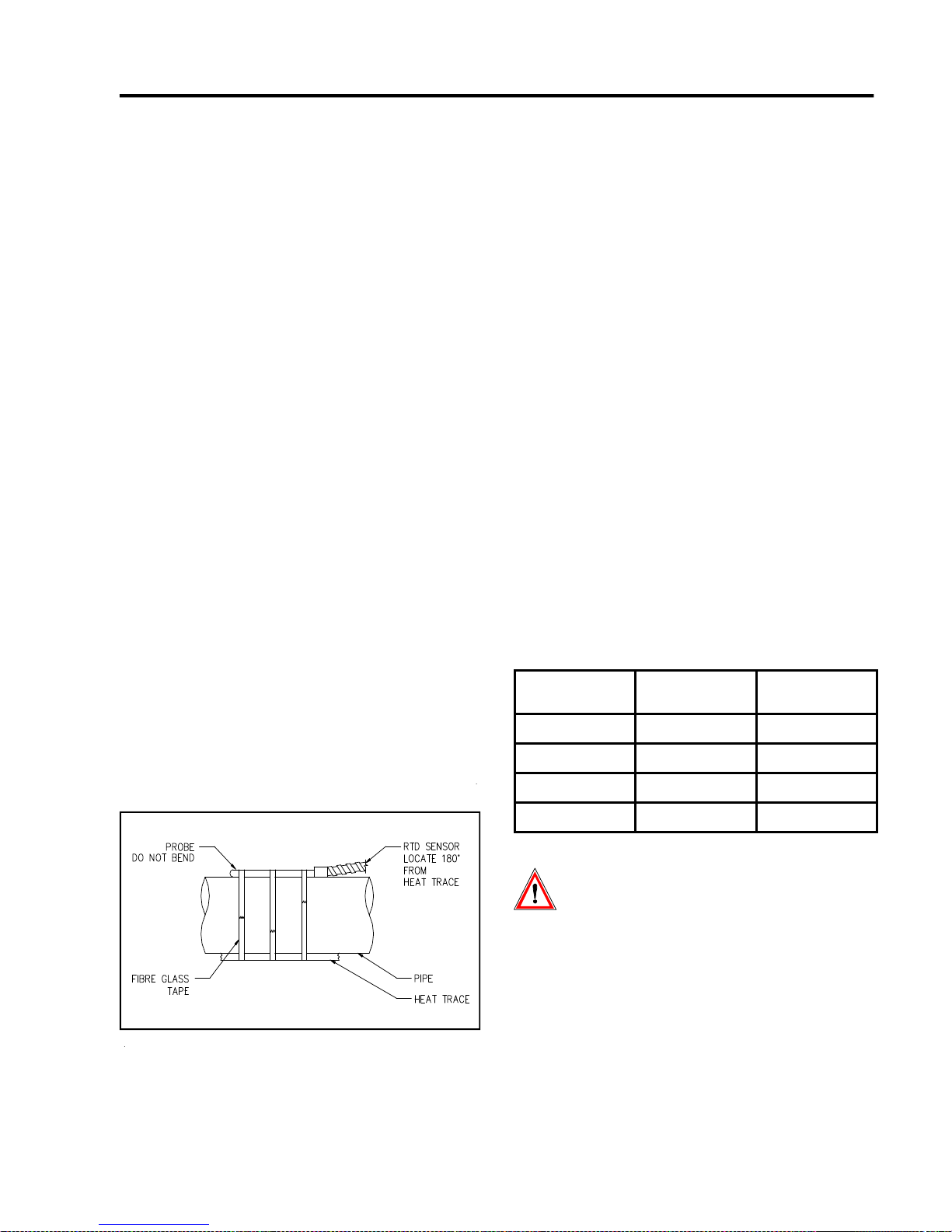
MASTERTRACE
4 Installation
Chapter 4 Installation
4.1 Control Panel Mounting
Mount the control panel at a convenient location, generally with the Interface Module at eye level. Placing the
Interface Module in direct sunlight may make reading the
display difficult.
Cut holes and mount hubs at suitable locations in the
enclosure as required. It is recommended that power
wires are run in separate conduits from RTD and RS-485
signal wires.
4.2 RTD Sensor Wiring
RTD Sensors should be 3-wire, 100 W, platinum to DIN
standard 43760. Mount the RTD element on the pipe,
away from the heat trace and 30° to 45° from the bottom
of the pipe. The total circuit resistance per conductor
from the RTD to the control panel must be less than 10
ohm. Exceeding this resistance will result in non-linear
temperature measurement. Beldon cable 8770 or
equivalent will allow RTDs to be placed up to 1,000 feet
from the control panel. Complete all RTD wiring
according to the Panel Layout Drawings located in the
control panel package.
The RTD sensor must be installed on the pipe surface or
thermal well before the pipe insulation to ensure proper
thermal contact. The RTD position should be 180° from
the electric heat trace cable which is the coldest spot of
the pipe. The RTD sensor may be secured to the pipe by
fiber-glass tape. The RTD probe is delicate and should
not be bent or used as a tool to puncture insulation. If
additional wiring is required for the RTD, shielded 3-lead
wire sized 18 or 20AWG must be used for the RTD
sensor to minimize the effects of noise pickup. A typical
RTD installation is shown in Figure 4.1.
4.3 Ground Fault Protection
In order for the ground fault protection to be effective, a
solid ground path must be provided for the heat trace.
Electrical heat trace with a grounded outer braid or
conductive sheath is recommended. For ground fault
monitoring, each heater circuit ground must be individually returned. Ground fautl protection is for equipment
protection only, not personnel.
4.4 Ground Fault Testing
To test the ground fault monitoring function on 5 and 10
point modules, a ground fault test function is available. A
90mA ac current source is provided on terminals 120 and
121 where a wire loop is inserted through all ground CTs
and terminated at the GF test terminals. The GF test wire
loop is internally wired on internal mechanical switch
models. See Typical Wiring Diagram in Appednix D for
details.
4.5 Power and Heater Wiring
Complete all supply and load wiring for the heater circuits
according to the Typical Wiring Diagram. Note that
voltages may vary by circuit. Power wiring should be
sized appropriately to the breaker size and maximum
ambient operating temperatures. Control panels with
breakers built-in will require a power feed size appropriately to the main breaker size.
Wire Size (AWG) Current Load (A)
6 30 50
8 30 40
Max. Ambient
Temperature (°C)
Figure 4.1 RTD Mounting
10 24 50
12 16 50
Wiring methods should comply with
Canadian Electrical or National Electrical
Code and local codes. Power and signal
wires should not be run in the same conduit
system. Wiring should be rated at least 90
°C. Wiring methods must conform to Class
1, Div.2 or Class 1, Zone 2 requirements.
4.6 Ground Connection
A dedicated ground wire must be connected to the ground
lug or bar on the control panel. This provides a solid
ground path in the event of a fault. The input transient
4.1
Page 34
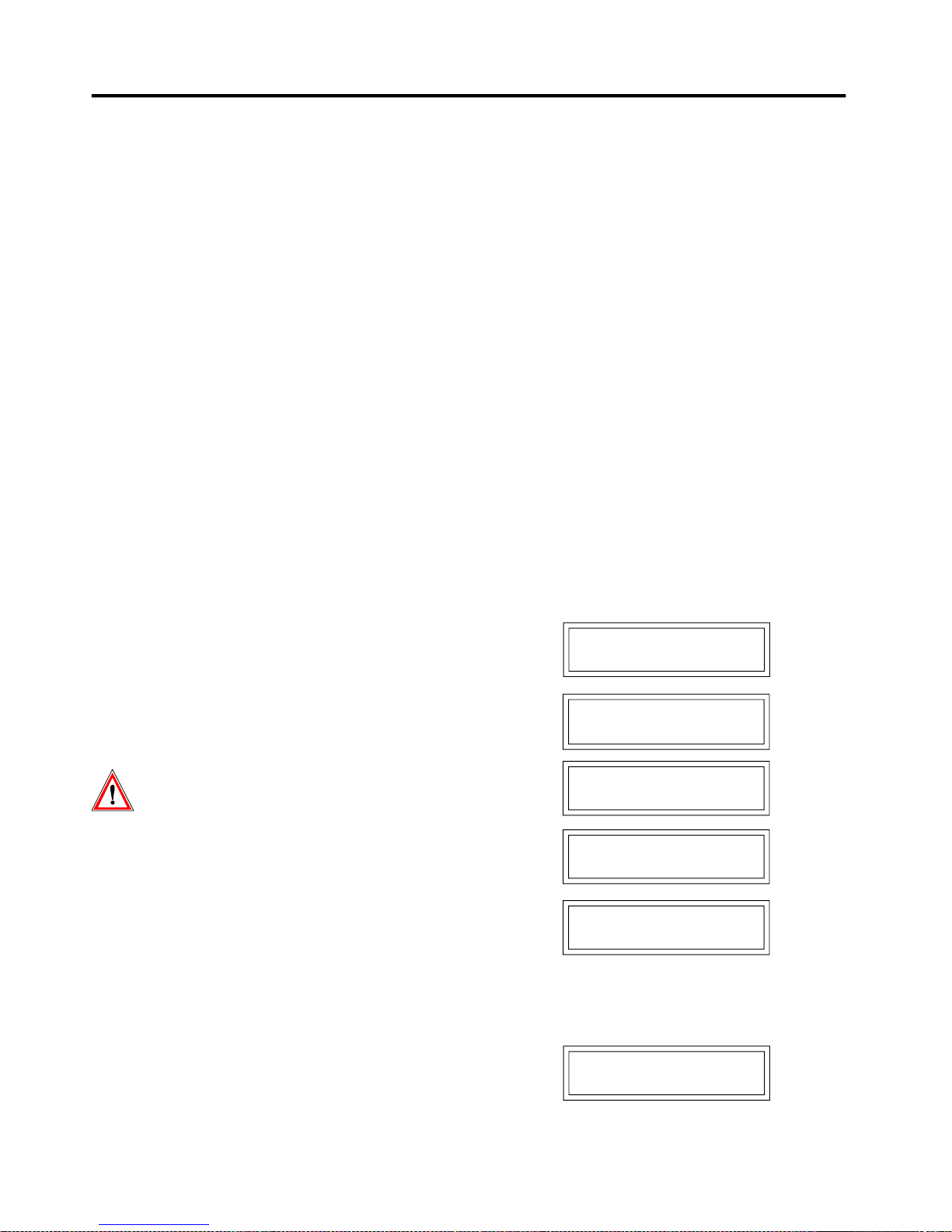
MASTERTRACE Chapter 4 Installation
protectors on the modules can not provide the necessary
protection without a solid ground.
4.7 Safety Ground
Each of the ten RTD inputs are protected by a transient
suppressor network which acts as a barrier against
transient energy pick-up by the RTD probe. In order for
this protection to work effectively, terminals 122 and 123
must be terminated to a solid ground separate from the
enclosure chassis ground. On panels pre-wired at the
factory, transient ground is tied to earth ground so that it
is not left open. It is recommended that transient ground
be disconnected from enclosure ground and moved to a
separate ground.
Note: The transient suppressor network is not an
intrinsically safe barrier and is only available on 5 and
10 point models.
4.8 Control Power Wiring
The control panel requires control power supplied from a
dedicated circuit breaker. The supply voltage for control
power to the MasterTrace modules is 120VAC. If the
supply voltage is incorrect, the modules may be damaged.
Control power must be protected by a circuit breaker no
larger than 15A. If the control panel includes a breaker
panel, control power connection to a branch breaker will
be already done at the factory. Recommended wire size
for control power wiring is 14 AWG at maximum ambient
temperature of 40°C and 12 AWG t maximum ambient
temperature of 50°C.
Wiring methods should comply with
Canadian Electrical or National Electrical
Code and local codes. Power and signal
wires should not be run in the same conduit
system. Wiring should be rated at least 90
°C. Wiring methods must conform to Class
1, Div.2 or Class 1, Zone 2 requirements.
4.9 Alarm Wiring
MR100 for Winsows CE only has one mechnical & NO
alarm contact and a hardware configurable LED alarm
output.
All other MasterTrace controllers have two alarm con-
tacts and one active alarm output for driving a LED alarm
indicator. Both the alarm contacts are software
configurable for normally open or closed. The alarm LED
output is software configurable for alarm on, alarm off or
flash during alarm. Refer to typical wiring diagrams in
Appendix D for alarm output terminals.
The mechanical alarm output is rated 30Vdc/10mA,
250Vac/0.5A in hazardous locations and 120Vac/1A,
30Vdc/0.1A in ordinary areas. The DC alarm output is an
opto-isolated transition output rated 30Vdc/100mA,
500mW max.
The alarm LED output is rated 12Vdc, 30mA. It can be
used to drive a 12Vdc LED indicator. Alarm outputs are
designed for interface to annunciator, panels, PLC or
DCS.
4.9 Commissioning
Commissioning the MasterTrace Control Panel requires
an understanding of its functions including how to display
measured values and, if necessary, to change setpoints or
configuration. Read Chapter 5: Operation and Chapter 6:
Programming & Setup before proceeding if you are not
familiar with the MasterTrace operation.
Once the wiring is complete and in accordance with the
Typical Wiring Diagram in Appendix D, close the circuit
breaker to provide control power to the panel.
For MR100 for Windows CE, a proper function page
appears on the touch screen after power-up. Refer to
Appendix G for the operation of MR100 for Windows CE.
For MR100/ML100 Interface Module, this sequence of
messages displays on power-up:
MASTERTRACE HEAT
TRACING CONTROL
NEXTRON CORP
(403) 735-9555
FIRMWARE VERSION:
REV. D1-05-00
MANUAL VERSION:
1501-0006_1
SELF TEST
PASSED
Refer to Appendix C: Summary of Alarms and Causes, if
the Self Test Failure alarm light turns on or the Interface
Module displays this message:
SELF TEST
FAILURE ALARM
4.2
Page 35
MASTERTRACE
Chapter 4 Installation
4.9.1 Enter Program Changes: Refer to the Programming
Sheet for Control Panel & Modules in the panel drawing if
it is available. If not, Refer to Figure 4.2 for Sample
Programming Worksheet. Ignoring the alarm messages
and lights, enter all required user setup changes. The
Program Enable edit box in MR100 for Windows CE or
Program Enable dip switch on the MR100/ML100 Interface Module must be set to ENABLE to allow programming. Refer to Figure 2 in Appendix G, or Figure 5.9 for
ML100 Dedicated Interface Module, or Figure 5.10 for
MR100 Group Interface Module. It is recommended that
this Program Enable edit box or dip switch be set to
DISABLE to prevent unauthorized entry of program
changes.
4.9.2 Turn On Heater Power: Close the circuit breakers
for all heat trace circuits controlled by the MasterTrace
control panel.
4.9.3 Respond to Alarm Conditions: Examine each alarm
condition and correct problems as required. High Current
and Low Temperature alarms should be ignored during
start-up and until normal operating levels have been
reached. Refer to Appendix C: Summary of Alarms and
Causes for information on potential causes of alarms.
There are no consumable components contained in any of
the models covered in this manual.
There is no cleaning requirements for any of the models
covered in this manual.
4.9.4 Check Actual Readings: Once the system has
reached normal operating temperatures, check the
individual temperature, current and ground fault current
readings against expected values for each circuit. This can
indicate wiring or design errors.
4.9.5 Check the RTD Wiring: Locate and open the
junction box or head of the selected RTD. Either
disconnect the RTD or short the wires. The RTD Short or
RTD Open alarm will be displayed on the Interface
Module showing the Heater Name. Confirm that the
displayed heater matches the heater of the selected RTD.
Warning - Explosion Hazard - Substitution
of components may impair suitablility for
Class 1, Division 2 or Class 1, Zone 2.
Warning - Explosion Hazard - Do not
disconnect equipment unless power has
been switched off or the area is known to be
non-hazardous.
Warning - The ground fault trip function is
intended for equipment protection only and
should not be used in place of ground fault
protection for personnel protection where
this is required.
Caution - Equipments are not evaluated for use
in a corrosive atmosphere.
4.3
Page 36
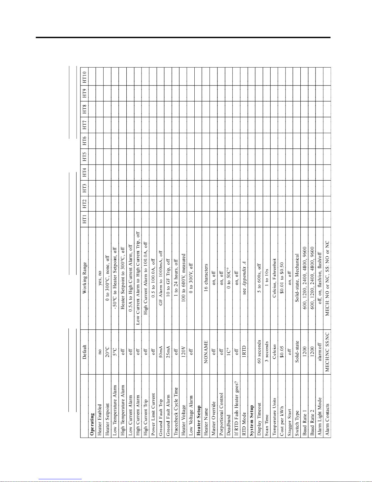
MASTERTRACE Chapter 4 Installation
NEXTRON CORPORATION
Mastertrace Rev.D1 Heat Tracing Controls
Heater Setpoint Programming Worksheet
Customer: Model Type: Date:
Panel No.: Module No.: S/N:
Figure 4.2 Sample Programming Worksheet
4.4
Page 37

MASTER
TRACE
Chapter 5
Operation
5 Operation
This section provides information on how to operate the
MasterTrace™ modules. Refer to the module name plate(s)
and Chapter 3.4, Model Codes, if you are unsure of your
product and its specific features.
5.1 Control Modules
Refer to the following Figures for the appropriate Control
Module(s).
• Figure 5.1: MS-1DIN2 & MS-2DIN2
• Figure5.2: MS-1TXH0
• Figure 5.3: MS-1DXH0 & MS-2DXH0
• Figure 5.4: MS-5ADXH0, MS-5A TXH0 & MS-10ADXH0
• Figure5.5: MS-5ADIN2 & MS-10ADIN2
• Figure5.6: MS-10ADIN2T
• Figure5.7: MS-10ADIN2X
5.1.1 Status Lights:
•L1 Power: Light is on when control power is present.
•L2 Heater: Each heater circuit has a light which is on
when the heater relay or contactor is closed.
•L3 Alarm: Light is on if there are one or more alarms on
any circuits of the Control Module.
•L4 Address: Light is on when Control Module is in
Address Enable Mode. Light must be on to allow the
Module Number to be changed from a master on the
data highway.
•L5 Transmit: Each serial port has a light which flashes
while the Control Module is transmitting information to
the data highway.
•L6 Receive: Each serial port has a light which flashes
while the Control Module is receiving information from
the data highway.
•L7 Override: Light is on when the Override Input termi-
nals are shorted. When light is on, all heaters which are
programmed with Master Override set to ON should be
on if their heater setpoints are set to off/none.
5.1.2 Switches & Jumpers:
•S1 Address Mode: When the switch is set to DISABLE,
the Module Number can’t be changed/read from a master
on the data highway. When set to ENABLE, the Module
Number can be changed/read for the ten minutes after
the module’s power-up from a master on the data highway. During this time the ADDRESS light is on.
•S2 RS485-120: When the jumper is set to IN, the RS-485
line is terminated by a 120 ohm resistor. Only the last
Control Module on the data highway should be set to IN.
5.1.3 Terminals: Refer to T ypical Wiring Diagrams for
Power, heater and R TD field connections.
Note: Not all models are equipped with the following.
•T1 Alarm Contacts: Alarm contact type is the same for
all models. In hazardous areas the opto-isolated dc output
is rated 30Vdc @ 0.1A (terminals 4 & 5) and the dry
mechanical output is rated 30Vdc@10mA, 250V [email protected]
(terminals 6 & 7). In ordinary areas the opto-isolated dc
output is rated the same as hazardous but the dry
mechanical output is rated 120Vac@1A, [email protected].
Contacts are configurable for normally open or closed.
•T2 Alarm Light Output: The output is configurable for
normally open, closed or flash. Output is rated 12 Vdc
@ 30 mA for an LED type lamp (MS-1 & MS-2 terminals
16+ & 17-, MS-5A and MS-10A terminals 13+ & 14-).
•T3 Master Override Input: Only those heaters which are
programmed with Master Override set to ON are affected
by Master Override Input. When the terminals are open,
all Master Override Enabled heaters are forced off. When
the terminals are closed, all Master Override Enabled heaters are controlled by their individual RTDs unless their
Heater Setpoints are set to off/none. In this case, the
heater is turned on. The logic of this input allows either
ambient temperature override or load shedding on all or
selected heaters. (MS-1 & MS-2 terminals 26+ & 27-, MS5A & MS-10A terminals 11+ & 12-).
•T4 RTD Input: 3 wire RTD input. Ground terminal con-
nects to shield or case. Lead resistance compensated.
For MS-1 & MS-2, terminals 8-15 are RTD inputs. For
MS-10A, terminals 60-99 are RTD A inputs, and terminals
160-199 are RTD B inputs. For MS-5A, all its R TD inputs
are in terminals 60-99 (60-63 for RTD 1A, 64-67 for R TD
1B, 68-71 for RTD 2A, 72-75 for R TD 2B, ..., 92-95 for R TD
5A, 96-99 for R TD 5B.).
•T5 Control Power Input:120Vac input, 2A fused (termi-
nals 2 & 3), earth ground (terminal 1).
•T6 CT’ s: Heater Current & Ground Fault monitoring trans-
formers (MS-1 & MS-2 terminals 28-35, MS-5A & MS10A terminals 20-59). Solid-state models only .
•T7 SSR’s: 12Vdc, 15mA max for driving digital input of
solid state relays (MS-1 & MS-2 terminals 40-43, MS-5A
& MS-10A terminals 100-1 19). Solid-state models only .
•T8 Voltage: Connect to heater input for voltage monitor-
ing. 300V ac max. (MS-1 & MS-2 terminals 36-39). One &
two-point single-phase solid-state models only.
•T9 Safety Ground: Terminate to solid ground separate
from panel ground for transient protection circuit on RTD
inputs. (MS-5A & MS-10A terminals 122 & 123). Five &
ten-point models only.
• T10 GF Test: Wire loop is passed through GF CTs &
terminated at the GF test terminals. An ac test current is
applied through wire loop during GF testing. (MS-5A &
MS-10A terminals 120 & 121). 5 & 10-point models only .
5.1
Page 38
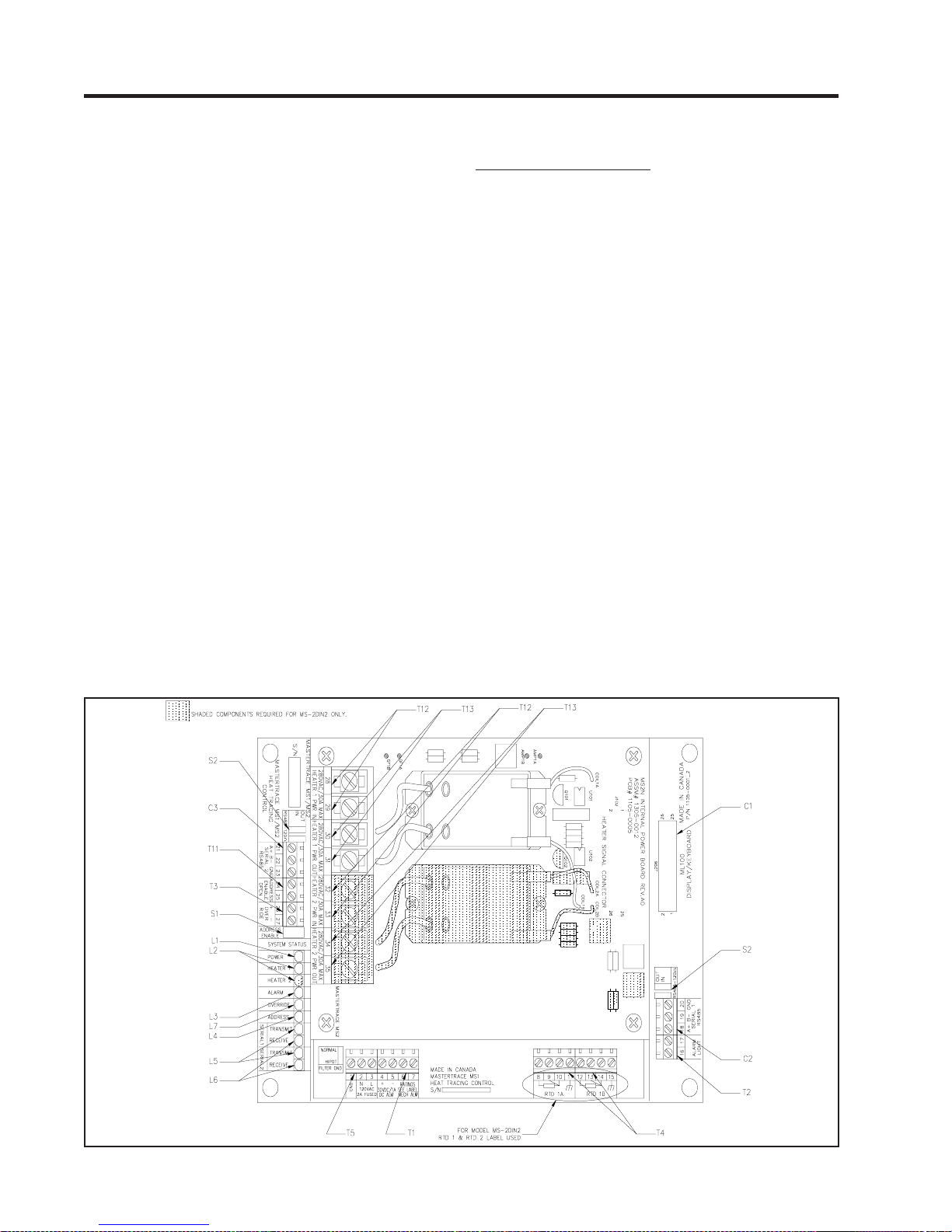
MASTER
TRACE Chapter 5
Operation
•T11 Address Enable Open: When the terminals are
shorted, the Module Number cannot be changed from a
master on the data highway . (MS-1 & MS-2 terminals 24
and 25). 1 & 2-point models only.
• T12 Heater Power Input: 280V ac max input voltage. (MS-
1 & MS-2 terminals 28, 29, 32 and 33, MS-5A & MS-10A
terminals 20-39). Mechanical models only .
• T13 Heater Power Output: 280Vac/30A max continuous
(MS-1A & MS-2A terminals 30, 31, 34 and 35, MS-5A &
MS-10A terminals 40-59). Mechanical models only .
• T14 +15Vdc Power Output: 15Vdc/0.2A. (MS-5A & MS-
10A T erminals 15 & 16). 5 & 10-point models only .
• T15 TC Input: Thermocouple input. There are 10 TC in-
puts, one per heater (T erminals 60 & 61 for TC1, 64 & 65
for TC2, ..., 96 & 97 for TC10). Connect TC’ s positive wire
to terminal marked as (+), and negative wire to terminal
marked as (-). Model MS-10ADIN2T only .
• T16 Xmitter Input: RTD Transmitter input. There are 10
Xmitter inputs, one per heater (Terminals 60 & 61 for
Xmitter1, 64 & 65 for Xmitter2, ..., 96 & 97 for Xmitter10).
T o connect with an R TD T ransmitter, use 18 AWG wires
to connect the terminal marked as + to the I(+) terminal on
R TD Transmitter , and the terminal marked as - to the I(-)
terminal on RTD Transmitter . The actual R TD sensor is to
be locally wired to the RTD Transmitter and the transmitter can be located up to 7km away from the control module. Model MS-10ADIN2X only.
Figure 5.1 MS-1DIN2 & MS-2DIN2 Control Module
• T17 +15Vdc Power Output: Model MS-10ADIN2X only.
5.1.4.Communications Ports:
•C1 ML100 Interface: Standard connection to a Dedi-
cated Interface Module via a ribbon cable.Maximum cable length is 4 feet.
•C2 Serial Port 1: Standard connection to an RS-485 data
highway via a 2-conductor, shielded, twisted pair cable.
Maximum Cable length with 30 Control Modules without
repeater is 4,000 feet. (MS-1 & MS-2 terminals 18+, 19-, 20
SHD, MS-5A & MS-10A terminals 8+, 9-, 10 SHD)
•C3 Serial Port 2: Standard connection to an RS-485 data
highway via a 2-conductor, shielded, twisted pair cable.
Maximum Cable length with 30 Control Modules without
repeater is 4,000 feet. (MS-1 & MS-2 terminals 21+, 22-, 23
SHD, MS-5A & MS-10A terminals 17+, 18-, 19 SHD)
•C4 Serial Port 3: Standard connection to an RS-485 data
highway via a 2-conductor, shielded, twisted pair cable.
Maximum Cable length with 30 Control Modules without
repeater is 4,000 feet. (MS-5A & MS-10A terminals 20+,
21-, 22 SHD). 5 & 10-point models only.
This port is specifically designed for the communication between the control module and the RTD Sampler. If
communication is conducted via wireless RF Modem, the
RS485 cable should be wired to the RF Modem mounted
on control module nearby. If communication is conducted
via RS485 cable, the RS485 cable should be connected to
the RTD Sampler’ s communicaiton port directly .
5.2
Page 39
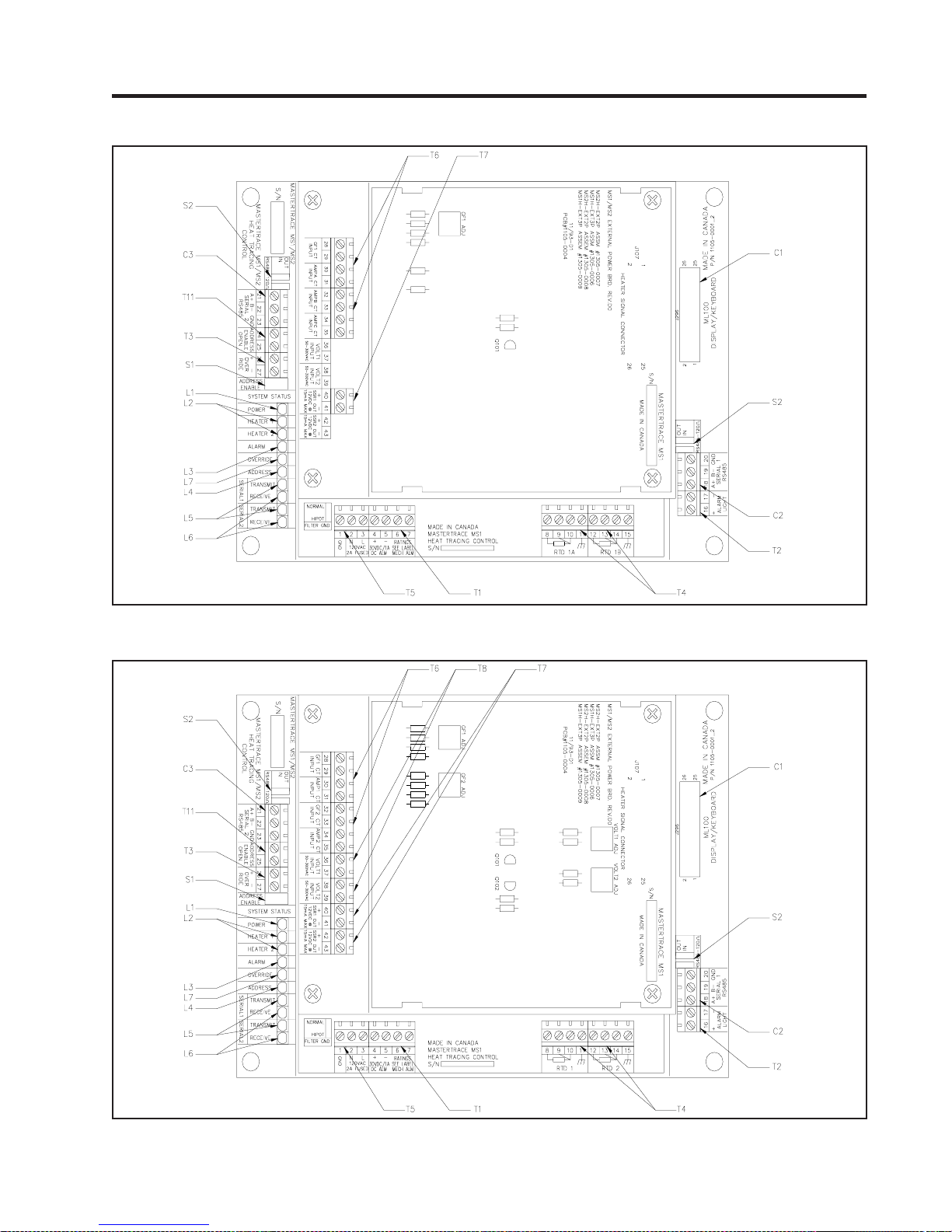
MASTER
Figure 5.2 MS-1TXH0 Control Module
TRACE
Chapter 5
Operation
Figure 5.3 MS-1DXH0 & MS-2DXH0 Control Modules
5.3
Page 40
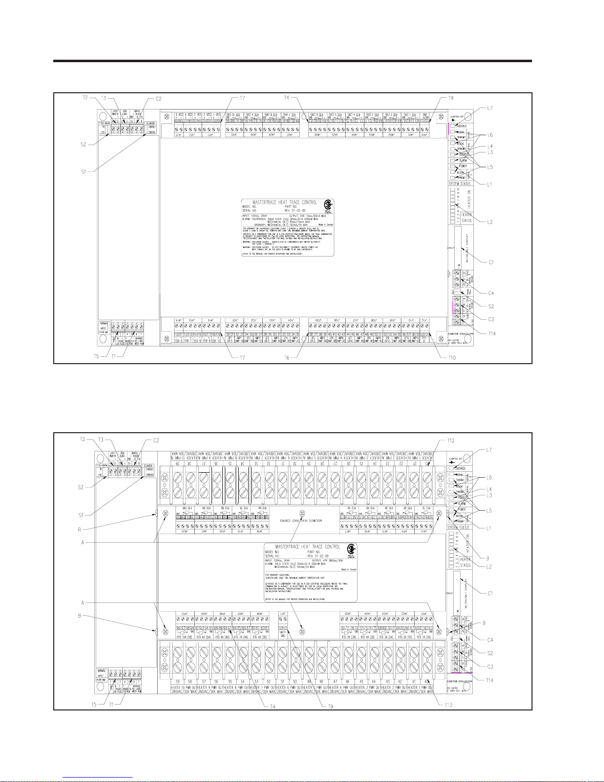
MASTER
Figure 5.4 MS-5ADXH0, MS-5ATXH0 & MS-10ADXH0 Control Modules
TRACE Chapter 5
Operation
Figure 5.5 MS-5ADIN2 & MS-10ADIN2 Control Modules
5.4
Page 41
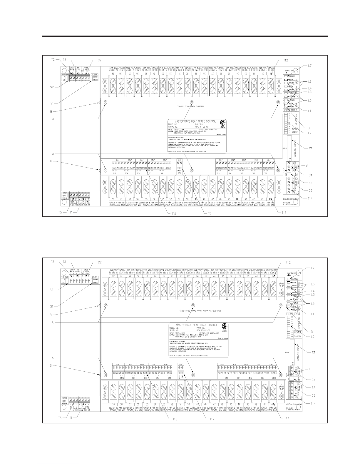
MASTER
Figure 5.6 MS-10ADIN2T Control Module
TRACE
Chapter 5
Operation
Figure 5.7 MS-10ADIN2X Control Module
5.5
Page 42

MASTER
5.2 Interface Modules - ML100 & MR100
The ML100 Dedicated Interface Module is capable of programming and monitoring one Control Module such as the
MS-10A. It is a “Dedicated” interface because it connects
to only one Control Module. It is designed to be doormounted in a NEMA-4 enclosure in an industrial environment. Operator interface is through the Status Indicators,
LCD Display and the Keypad. Refer to Figure 5.8 and Fig-
ure 5.9.
The MR100 Group Interface Module is capable of programming and monitoring from one to thirty Control Modules. It
is a “Group” interface because it connects, via a serial cable
to several Control Modules. It is designed to be doormounted in a NEMA-4 enclosure in an industrial environment. Operator interface is through the Status Indicators,
LCD Display and the Keypad. Refer to Figure 5.8 and Fig-
ure 5.10.
5.2.1 Status Lights Located on Circuit Board :
•L8 Transmit: LED flashes when the Interface Module is
transmitting information to the data highway. MR100 only .
•L9 Receive: LED flashes when the Interface Module is
receiving information from the data highway. MR100 only .
5.2.2 Switches and Jumpers:
•S3 Program Enable: When the Program Enable dip switch
is set to DISABLE, programming is disabled and setpoints
and configuration cannot be changed. Otherwise, programming is allowed.
5.2.3 Terminals: Refer to the Typical Wiring Diagrams
for power field connections.
• T14 Alarm Contacts: In hazardous areas the dc output
is rated 30Vdc @ 0.1A (terminals 906 and 907) and the dry
mechanical output is rated 30Vdc @ 10mA, 250Vac @
0.5A (terminals 904 and 905). In ordinary areas the dc
output is rated the same as hazardous but the dry mechanical output is rated 120Vac @ 1A, 30Vdc @ 0.1A.
Contacts are configurable for normally open or closed.
MR100 only.
• T15 Alarm Light Output: The output is configurable or
normally open, closed or flash. Output is rated 12 Vdc @
30 mA for an LED type lamp (terminals 909+ and 908-).
MR100 only.
• T16 Control Power Input:120V ac input (terminals 902 and
903), earth ground (terminal 901). MR100 only.
• T17 Power OUT/IN terminals: T erminals 913 (POUT) &
914 (PIN) are designed to interface with 3rd party 4-20mA
RTD Transmitter for temperature measurement. 913 (+15V)
is dc current source terminal and 914 is dc current return
terminal. To connect with an RTD Transmitter, use 18
A WG wires to connect terminal 913 to the I(+) terminal on
TRACE Chapter 5
Operation
RTD Transmitter , and terminal 914 to the I(-) terminal on
R TD Transmitter . The actual R TD sensor is to be locally
wired to the RTD T ransmitter and the transmitter can be
located up to 7km away from MR100. Refer to Appendix E
for the operation detail of RTD Transmitter . MR100 only .
5.2.4 Communications Port:
•C4 Parallel Port: Standard connection to a single Control
Module via a ribbon cable. Maximum cable length is five
feet. ML100 only.
•C5 Serial Port : Standard connection to an RS-485 data
highway via a 2-conductor, shielded, twisted pair cable.
Maximum Cable length with 30 Control Modules without
repeater is 4,000 feet. (terminals 912+, 911-, 910 SHD).
MR100 only.
5.2.5 Trim Potentiometers:
•P1 LCD display: Adjusts the contrast according to the
viewing angle.
5.2.6 Status Lights Located on Faceplate :
• L10 Power: The green Power light should be on at all
times indicating that control power is applied to the Interface Module. If the light is off either there is no voltage across terminals 902 and 903 or the Interface Module
has a malfunction and requires servicing.
•L11 Heater: The green Heater light is on if the selected
heater is energized.
• L12 Communicate: Random flashing of the green Com-
municate light indicates that serial communications are
active on the Control Module to which it is connected.
• L13 System Fail: The red System Fail light should be off,
indicating that the system check was successful. On the
Dedicated Interface Module, if the light is on, the Control
Module has failed its self-test and requires servicing. On
the Group Interface Module, if the light is on, the Group
Interface Module has failed its self-test and requires servicing.
• L14 Alarm: The red alarm light is off when there are no
alarms. The light will flash if any alarm conditions are
present. Press [ST ATUS] to view alarms.
5.2.7 Alphanumeric Display:
•D1 Display: T wo lines with sixteen alphanumeric charac-
ters per line. It is backlit for viewing in low-light conditions.
5.2.8 Keypad:
•K1 Interface Module Keypad: Consists of nine keys
which, when used in connection with the Alphanumeric
Display , allow complete control of programming and monitoring of any Control Module connected to the Interface
Module.
5.6
Page 43

MASTER
TRACE
Chapter 5
Operation
The [SETPOINT] key provides entry to the Setpoint Menu
which allows the user to program and test all connected
Control Modules.
The Setpoint Menu is arranged in four columns. Quickly
pressing [SETPOINT] twice accesses the top of the second
column; pressing three times accesses the top of the third
column, and so on.
The [MEASURED] key provides entry to the Measured
V alues Menu which allows the user to display the measured
values for all connected Control Modules. The Measured
Values Menu is arranged in three columns. Quickly pressing [MEASURED] twice accesses the top of the second
column; pressing three times accesses the top of the third
column.
The [STATUS] key provides immediate access to the System Status Menu which displays the alarm status for all
connected Control Modules and allows access to individual
alarm details.
The [MESSAGE ñ] key allows the user to move up through
the selected menu.
The [MESSAGE ò] key allows the user to move down
through the selected menu.
The [V ALUE ñ] key allows the user to increase the value of
the displayed selected item.
The [V ALUE ò] key allows the user to decrease the value of
the displayed selected item.
The [STORE] key allows the user to save the changed value
of the selected item.
The [RESET] key allows the user to clear alarms that are no
longer active.
5.2.9 Heater Numbering: Each heater is identified by a number
of the form “M-H”, where “M” is the Module Number and
“H” is the local heater number. Ten-point Control Modules
have local heater numbers from “1” through “10”. Each
Control Module on the same data highway must have a
unique Module Number.
5.2.10 Example: Display the Heater Control T emperature for
Heater 3-2
Press [MEASURED] to enter the Measured Values Menu
as shown:
MEASURED
OPERATING VALUES
SELECT HT: 3-2?
NONAME
Press [V ALUE ñ] or [V ALUE ñ] to select Heater 3-2. Press
[STORE].
Press [MESSAGE ò] until the desired value is displayed as
shown:
HEA TER CONTROL
TEMP: 55°C
&
&
Figure 5.8 ML100 & MR100 Interface Modules, Front V iew
5.7
Page 44
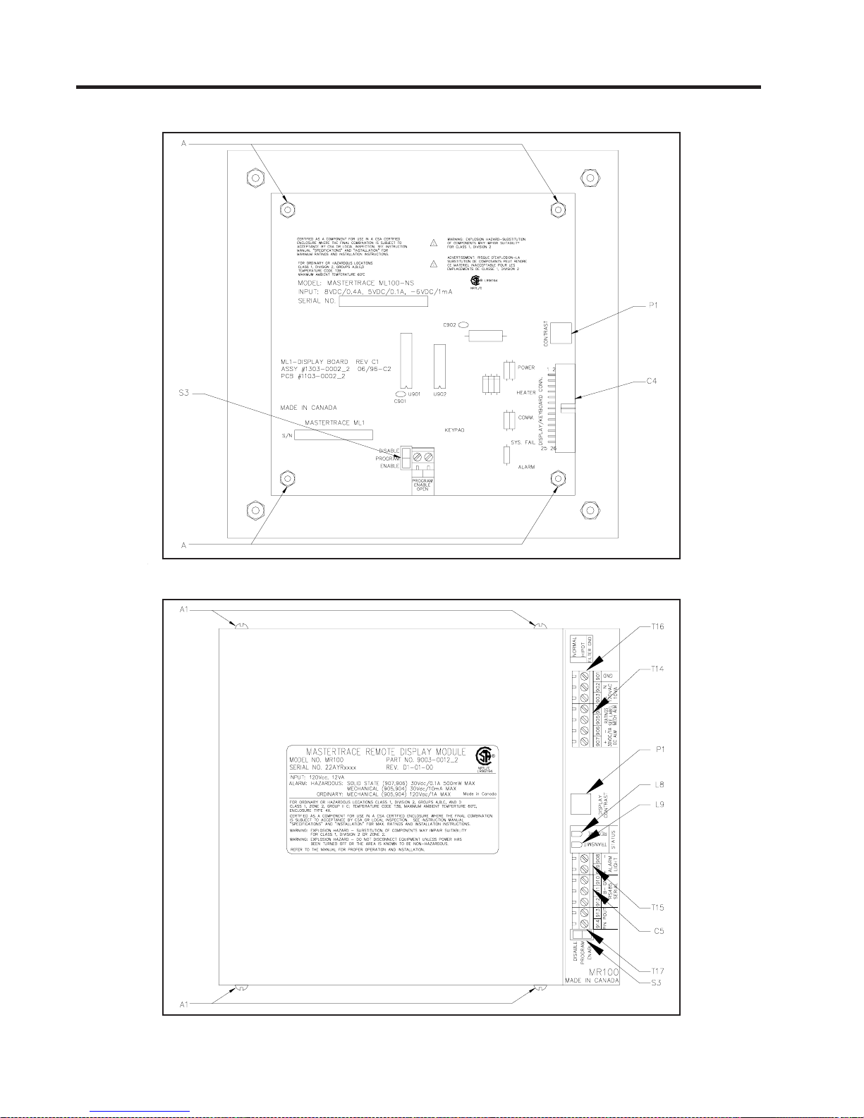
MASTER
Figure 5.9 ML100 Dedicated Interface Module, Rear V iew
TRACE Chapter 5
Operation
Figure 5.10 MR100 Group Interface Module, Rear V iew
5.8
Page 45
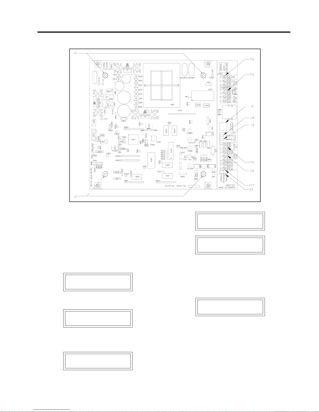
MASTER
Figure 5.11 MR100 Group Interface Module, Cover Removed
TRACE
Chapter 5
Operation
5.3 Responding to Alarms
The [STATUS] key provides immediate access to the System Status Menu which displays the alarm status for all
connected Control Modules. If the Default Display is programmed to System Status, the System Status Menu will
automatically be displayed after a period of time equal to
the Display Timeout has expired from last key press.
If there are no alarms, this message is displayed:
SYSTEM OK
NO ALARMS
If there are one or more alarms, this message is displayed:
** 2 ALARMS**
PRESS MSSG DOWN
Pressing [MESSAGE ò] displays the alarm detail screens
for each alarm as shown:
LOW TEMPERA TURE
ALARM
HEA TER 2-1
NONAME
ACTUAL: 3°C
SETPOINT: 5°C
The first screen shows what the alarm is, the second shows
where the alarm is and the third screen shows why there is
an alarm. The Scan Time determines the rate at which these
screens are displayed.
If there no more alarms, this message is displayed:
NO MORE ALARMS
Refer to Appendix C: Summary of Alarms and Causes for
information on reasons for the alarms. After the cause of
each alarm has been corrected, any non-latching alarm will
clear. Latching alarms (All Trip and TraceCheck™ alarms)
must be reset to clear the alarm. To reset the alarm, first
display the alarm detail screens and then press [RESET].
&
5.9
Page 46
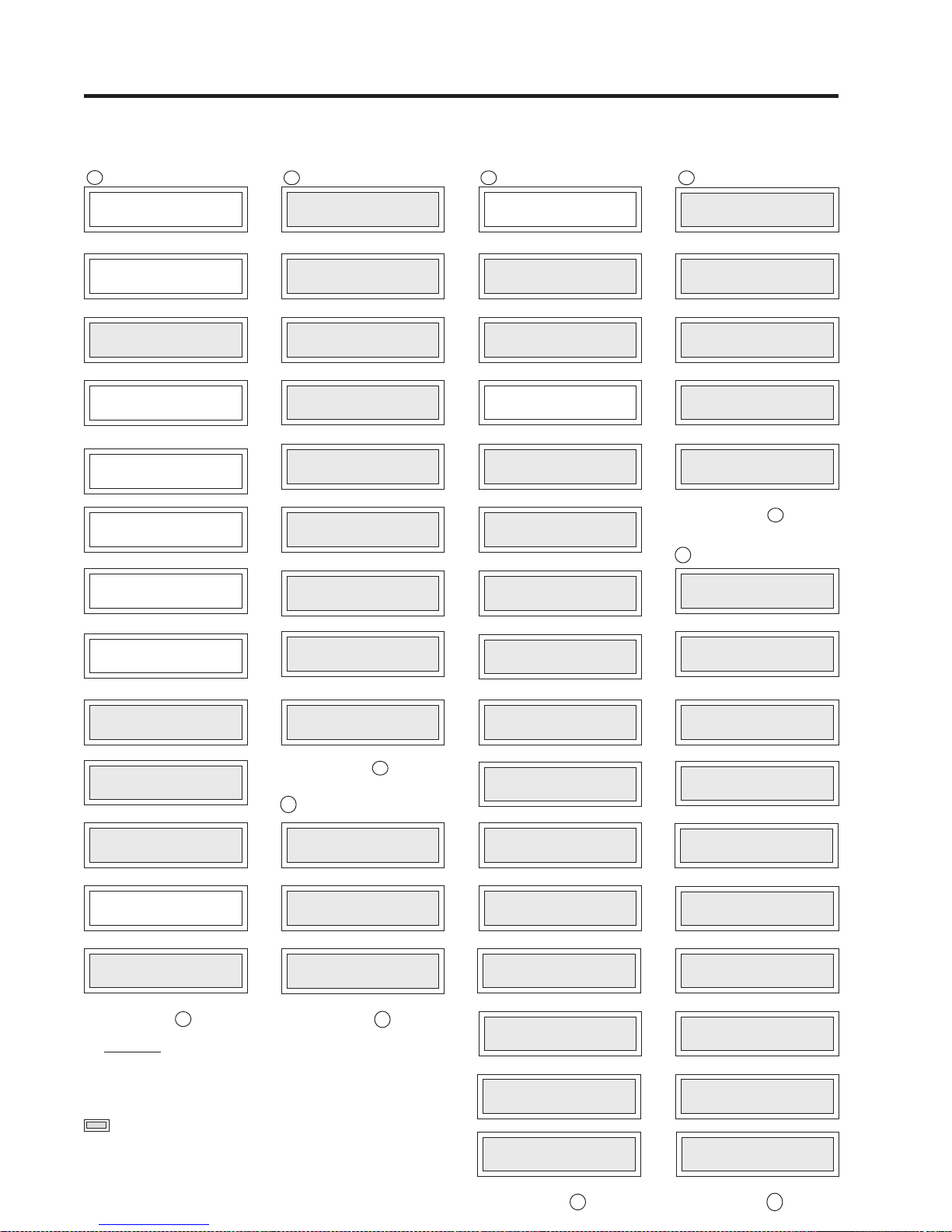
MASTER
TRACE Chapter 5
5.4 Setpoint Values Menu: Single-Phase Modules
Operation
[SETPOINT]
1
OPERA TING V ALUES
HEA TER ENABLED?
HEA TER SETPOINT:
LOW TEMPERA TURE
HIGH TEMPERA TURE
TRACECHECK CYCLE
Restrictions
1 1- & 2-point Modules
2 5- & 10-point Modules
3 Dual RTD Modules
4 Solid-State Switch Modules
5 MR100 Interface Module
Advanced User Mode
ò
SETPOINTS:
[MESSAGEô ]
SELECT HT:1-1?
NONAME &
[MESSAGEô ]
?
yes
[MESSAGEô ]
?
5°C
[MESSAGEô ]
ALARM: 2°C
[MESSAGEô ]
ALARM: off
[MESSAGEô ]
LOW CURRENT
ALARM: off
[MESSAGEô ]
HIGH CURRENT
ALARM: off
[MESSAGEô ]
HIGH CURRENT
TRIP: off
[MESSAGEô ]
POWER LIMIT
CURRENT: off
[MESSAGEô ]
GROUND FAULT
TRIP: 30mA
[MESSAGEô ]
GROUND FAULT
ALARM: 20mA
[MESSAGEô ]
TIME: off
[MESSAGEô ]
?
?
go to 2
?
?
?
?
?
?
?
ðð
3 4
HEA TER SETUP
SELECT HT: 1-1?
HTR 1-1 NAME:
MASTER OVERRIDE:
PROPORTIONAL
CONTROL: off
HEATER GOES: off
COPY TO OTHER
HEATERS: no
4
2
TRACECHECK HTR ON
TIME: 0.5 MIN ?
HEA TER VOL T AGE:
LOW VOL T AGE:
[SETPOINT]
ò
SETPOINTS:
[MESSAGEô ]
NONAME &
[MESSAGEô ]
?
off
?
2 C°
go to 4
?
120V
go to 3
?
?
NONAME
[MESSAGEô ]
[MESSAGEô ]
[MESSAGEô ]
DEADBAND
[MESSAGEô ]
IF RTD F AILS
[MESSAGEô ]
RTD MODE
2 RTDs, lowest
[MESSAGEô ]
[MESSAGEô ]
[MESSAGEô ]
[MESSAGEô ]
ALARM: off
[MESSAGEô ]
[SETPOINT]
ò
SETPOINTS:
SYSTEM SETUP
[MESSAGEô ]
MODULE LIST:
MOD: 1? SEL:yes?
[MESSAGEô ]
MODULE RANGE:
DISPLA Y MODE:
?
4
DEFAUL T DISPLA Y :
system status
DISPLA Y TIMEOUT :
?
3
?
2
2
1
5.10
TEMPERATURE
UNITS: celcius
COST PER kWh:
ST AGGER ST AR T :
NUM OF AMB SENSE
AMBIENT SENSING
HEATER: None
AMBIENT RTD
TEMP: 5°C
BAUD RATE MR100:
BAUD RATE 1:
?
1-30
[MESSAGEô ]
?
?
off
?
?
go to 5
?
?
?
?
&
?
normal user
[MESSAGEô ]
[MESSAGEô ]
60 seconds
[MESSAGEô ]
SCAN TIME:
3 seconds
[MESSAGEô ]
[MESSAGEô ]
$0.05
[MESSAGEô ]
[MESSAGEô ]
HTRS: 0
[MESSAGEô ]
[MESSAGEô ]
[MESSAGEô ]
RTD BOARD:
On Board
[MESSAGEô ]
1200
[MESSAGEô ]
1200
[MESSAGEô ]
?
?
?
ð
6
5
5
5
5
5
2
5
[SETPOINT]
ò
SETPOINTS:
SETPOINTS TEST
[MESSAGEô ]
MANUAL HEATER:
disabled ?
[MESSAGEô ]
MANUAL ALARM:
[MESSAGEô ]
MANUAL SYSTEM:
ALARM: disabled
[MESSAGEô ]
[MESSAGEô ]
disabled
GF TEST:
test now
go to 1
?
?
?
ò
BAUD RATE 2:
[MESSAGEô ]
ALARM LIGHT MODE:
ALARM CONTACTS:
MECH: NC
RESET CONTROL
MODULE? no
NUMBER: no
READ MODULE
RESET MR100:
FIRMW ARE VERSION:
MANUAL VERSION:
FOR ASSIST ANCE:
?
1200
?
?
no
D1-02-01
go to 6
?
SS: NC
?
alarm off
[MESSAGEô ]
[MESSAGEô ]
[MESSAGEô ]
SET MODULE
[MESSAGEô ]
NUMBER: 1
[MESSAGEô ]
[MESSAGEô ]
[MESSAGEô ]
1501-0006_1
[MESSAGEô ]
(403) 735-9555
[MESSAGEô ]
?
?
?
5
2
5
5
5
Page 47
MASTER
TRACE
5.5 Setpoint Values Menu: Three-Phase Modules (1- and 5-point only)
[SETPOINT]
1
OPERA TING V ALUES
HEA TER ENABLED?
HEA TER SETPOINT:
LOW TEMPERA TURE
HIGH TEMPERA TURE
A: HIGH CURRENT
B: HIGH CURRENT
C: HIGH CURRENT
C: HIGH CURRENT
Restrictions
1 5- & 10-point Modules
2 MR100 Interface Module
Advanced User Mode
ò
SETPOINTS:
[MESSAGEô ]
SELECT HT:1-1?
NONAME &
[MESSAGEô ]
?
yes
[MESSAGEô ]
?
5°C
[MESSAGEô ]
ALARM: 2°C
[MESSAGEô ]
ALARM: off
[MESSAGEô ]
A: LOW CURRENT
ALARM: off
[MESSAGEô ]
B: LOW CURRENT
ALARM: off
[MESSAGEô ]
C: LOW CURRENT
ALARM: off
[MESSAGEô ]
ALARM: off
[MESSAGEô ]
ALARM: off
[MESSAGEô ]
ALARM: off
[MESSAGEô ]
A: HIGH CURRENT
TRIP: off
[MESSAGEô ]
B: HIGH CURRENT
TRIP: off
[MESSAGEô ]
TRIP: off
[MESSAGEô ]
go to 2
?
?
?
?
?
?
?
?
?
?
?
ððð
3
2
TRACECHECK HTR ON
[SETPOINT]
ò
SETPOINTS:
HEA TER SETUP
[MESSAGEô ]
SELECT HT: 1-1?
NONAME &
[MESSAGEô ]
HTR 1-1 NAME:
NONAME
[MESSAGEô ]
MASTER OVERRIDE:
[MESSAGEô ]
PROPORTIONAL
CONTROL: off
[MESSAGEô ]
DEADBAND
[MESSAGEô ]
IF RTD F AILS
HEATER GOES: off
[MESSAGEô ]
RTD MODE:
2 RTDs, lowest
[MESSAGEô ]
COPY TO OTHER
HEATERS: no
[MESSAGEô ]
POWER LIMIT
CURRENT: off
[MESSAGEô ]
GROUND F AUL T
TRIP: 30mA
[MESSAGEô ]
GROUND FAULT
ALARM: 20mA
[MESSAGEô ]
TRACECHECK CYCLE
TIME: off
[MESSAGEô ]
TIME: 0.5 MIN
[MESSAGEô ]
HEA TER VOL T AGE:
[MESSAGEô ]
?
off
2 C°
go to 4
120V
go to 3
?
?
?
?
?
?
?
?
?
?
?
?
1
1
5.11
[SETPOINT]
4
MOD: 1? SEL:yes?
DEFAUL T DISPLA Y :
DISPLA Y TIMEOUT :
NUM OF AMB SENSE
AMBIENT SENSING
MR100 BAUD RATE:
ò
SETPOINTS:
SYSTEM SETUP
[MESSAGEô ]
MODULE LIST:
[MESSAGEô ]
MODULE RANGE:
DISPLA Y MODE:
TEMPERATURE
UNITS: celcius
COST PER kWh:
ST AGGER ST AR T :
HEATER: None
AMBIENT RTD
TEMP: 5°C
BAUD RATE 1:
?
1-30
[MESSAGEô ]
normal user
[MESSAGEô ]
system status
[MESSAGEô ]
60 seconds
[MESSAGEô ]
SCAN TIME:
3 seconds
[MESSAGEô ]
[MESSAGEô ]
$0.05
[MESSAGEô ]
?
off
[MESSAGEô ]
HTRS: 0
[MESSAGEô ]
[MESSAGEô ]
[MESSAGEô ]
RTD BOARD:
On Board
[MESSAGEô ]
1200
[MESSAGEô ]
1200
[MESSAGEô ]
go to 5
Chapter 5
6
2
2
?
?
Operation
[SETPOINT]
ò
SETPOINTS:
SETPOINTS TEST
[MESSAGEô ]
MANUAL HEATER:
disabled ?
[MESSAGEô ]
MANUAL ALARM:
[MESSAGEô ]
MANUAL SYSTEM:
ALARM: disabled
[MESSAGEô ]
[MESSAGEô ]
disabled
GF TEST:
test now
go to 1
?
?
?
2
1
?
5
?
?
?
?
2
?
2
&
?
?
1
2
?
BAUD RATE 2:
[MESSAGEô ]
ALARM LIGHT MODE:
[MESSAGEô ]
ALARM CONT ACTS:
MECH: NC
[MESSAGEô ]
RESET CONTROL
MODULE? no
[MESSAGEô ]
SET MODULE
NUMBER: no
[MESSAGEô ]
READ MODULE
NUMBER: 1
[MESSAGEô ]
RESET MR100:
[MESSAGEô ]
FIRMW ARE VERSION:
[MESSAGEô ]
MANUAL VERSION:
[MESSAGEô ]
FOR ASSIST ANCE:
(403) 735-9555
[MESSAGEô ]
?
1200
alarm off
?
SS: NC
?
no
D1-02-01
1501-0006_1
go to 6
?
?
?
?
?
2
2
2
Page 48
MASTER
TRACE Chapter 5
5.6 Measured Values Menu: Single-Phase Modules
Operation
[MEASURED]
1
OPERA TING V ALUES
HEA TER CONTROL
HEA TER AT 100%
HEA TER CURRENT :
HEA TER VOL T AGE:
CURRENT: 5mA
ò
MEASURED
[MESSAGEô ]
SELECT HT:1-1?
NONAME &
[MESSAGEô ]
HEA TER IS ON
& NO ALARMS
[MESSAGEô ]
TEMP: 6°C
[MESSAGEô ]
RTD-A ACTUAL
TEMP: 6°C
[MESSAGEô ]
RTD-B ACTUAL
TEMP: 6°C
[MESSAGEô ]
POWER
[MESSAGEô ]
4.6A
[MESSAGEô ]
120V
[MESSAGEô ]
GROUND FAULT
[MESSAGEô ]
go to 2
&
&
&
&
&
&
&
&
ð
2
2
[MEASURED]
2 3
MIN TEMPERA TURE:
MAX TEMPERA TURE:
CURRENT: 4.7A
MAX GROUND FAULT
CURRENT: 6mA
ò
MEASURED
STATISTICS
[MESSAGEô ]
SELECT HT: 1-1?
NONAME &
[MESSAGEô ]
3°C
&
[MESSAGEô ]
25°C
&
[MESSAGEô ]
MAX HEA TER
[MESSAGEô ]
[MESSAGEô ]
go to 3
&
&
1
ENERGY USED LAST
DAY: 2.1 kWh &
[MESSAGEô ]
TOT AL ENERGY
USED: 42.2 kWh &
[MESSAGEô ]
ENERGY COST
LAST DAY: $1.70 &
[MESSAGEô ]
TOT AL ENERGY
COST: $33.92 &
[MESSAGEô ]
TIME SINCE RESET
48 hrs &
[MESSAGEô ]
HEA TER ON TIME:
80 hrs &
[MESSAGEô ]
HEA TER IS ON
& 17% OF THE TIME
[MESSAGEô ]
TOT AL RUN TIME:
20966 hrs &
[MESSAGEô ]
RESET ST ATISTICS?
no &
[MESSAGEô ]
go to 1
Restrictions
1 1- & 2-point Modules
2 Dual RTD Modules
Advanced User Mode
5.12
Page 49
MASTER
TRACE
5.7 Measured Values Menu: Three-Phase Modules
Chapter 5
Operation
[MEASURED]
1
OPERA TING V ALUES
HEA TER CONTROL
HEA TER AT 100%
A:HEA TER CURRENT :
B:HEA TER CURRENT :
C:HEA TER CURRENT :
ò
MEASURED
[MESSAGEô ]
SELECT HT:1-1?
NONAME &
[MESSAGEô ]
HEA TER IS ON
& NO ALARMS
[MESSAGEô ]
TEMP: 6°C
[MESSAGEô ]
RTD-A ACTUAL
TEMP: 6°C
[MESSAGEô ]
RTD-B ACTUAL
TEMP: 6°C
[MESSAGEô ]
POWER
[MESSAGEô ]
4.6A
&
[MESSAGEô ]
4.6A
&
[MESSAGEô ]
4.6A
&
[MESSAGEô ]
&
&
&
&
&
ð
[MEASURED]
2 3
MIN TEMPERA TURE:
MAX TEMPERA TURE:
CURRENT: 4.7A
CURRENT: 4.7A
CURRENT: 4.7A
MAX GROUND FAULT
CURRENT: 6mA
ò
MEASURED
STATISTICS
[MESSAGEô ]
SELECT HT: 1-1?
NONAME &
[MESSAGEô ]
3°C
&
[MESSAGEô ]
25°C
&
[MESSAGEô ]
A:MAX HEA TER
[MESSAGEô ]
B:MAX HEA TER
[MESSAGEô ]
C:MAX HEA TER
[MESSAGEô ]
[MESSAGEô ]
go to 3
&
&
&
&
ENERGY USED LAST
DAY: 2.1 kWh &
[MESSAGEô ]
TOT AL ENERGY
USED: 42.2 kWh &
[MESSAGEô ]
ENERGY COST
LAST DAY: $1.70 &
[MESSAGEô ]
TOT AL ENERGY
COST: $33.92 &
[MESSAGEô ]
TIME SINCE RESET
48 hrs &
[MESSAGEô ]
HEA TER ON TIME:
80 hrs &
[MESSAGEô ]
HEA TER IS ON
& 17% OF THE TIME
[MESSAGEô ]
TOT AL RUN TIME:
20966 hrs &
[MESSAGEô ]
RESET ST ATISTICS?
no &
[MESSAGEô ]
go to 1
GROUND FAULT
CURRENT: 5mA
[MESSAGEô ]
go to 2
&
Restrictions
Advanced User Mode
5.13
Page 50
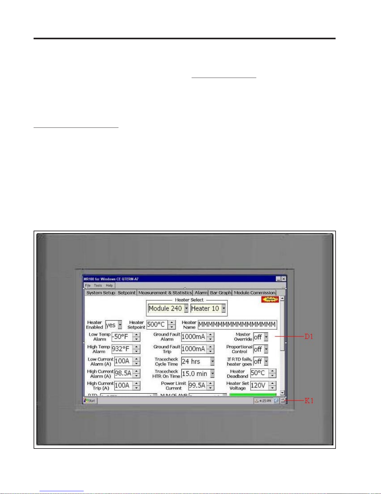
MASTER
5.8 Interface Module - MR100 for Windows CE
The MR100 for Windows CE Group Interface Module is
capable of programming and monitoring from one to thirty
Control Modules. It is a “Group” interface because it connects, via a serial cable to several Control Modules. It is
designed to be door-mounted in a NEMA-4/4X enclosure
in an industrial environment. Operator interface is through
the 7” touch screen and the on-screen keyboard. Refer to
Figure 5.12 and Figure 5.13.
5.8.1 Touch Screen and Keyboard:
•D1 Touch Screen: The 7” touch screen is the primary
working area of MR100 for Windows CE. It dislays all
kinds of information which MR100 for WIndows CE gathers from each heat-tracing controller in the network. Refer to Appdendix G - MR100 for Windows CE for the
detailed operation of the touch screen.
•K1 Keyboard: The on-screen keyboard can be activated
or hidden through a simple click on the iCon located atthe
bottom. Quite often in the operation of MR100 for W indows CE, keyboard is needed to input the digital values
TRACE Chapter 5
Operation
for heater setpoints and text characters for heater names.
5.8.2 Terminals & Jumper: Refer to the T ypical W iring
Diagrams for power field connections.
•T1 Alarm Contact (terminals A1 and A2): In hazardous
areas, the dry mechanical output is rated 30Vdc @ 10mA,
250V ac @ 0.25A. In ordinary areas, it is rated 120Vac @
0.5A, 30Vdc @ 0.1A.
•T2 Serial Port (terminals A+ and B-): Standard connec-
tion to an RS-485 data highway via a 2-conductor twisted
pair cable. Maximum cable length with 30 Control Modules without repeater is 4,000 feet.
•T3 Power Input (terminal +15V and GND): 12Vdc @ 850mA
power input.
•T4 Alarm Light Output (terminals C+ and C-): The output
is rated 12Vdc @ 30mA for an LED type lamp.
•J1Alarm Light LED Selection Jumper: For green LED,
place the jumper cap close to “G” mark. For red LED,
place the jumper cap away from “G” mark.
Figure 5.12 MR100 for Windows CE Group Interface Module, Front V iew
5.14
Page 51
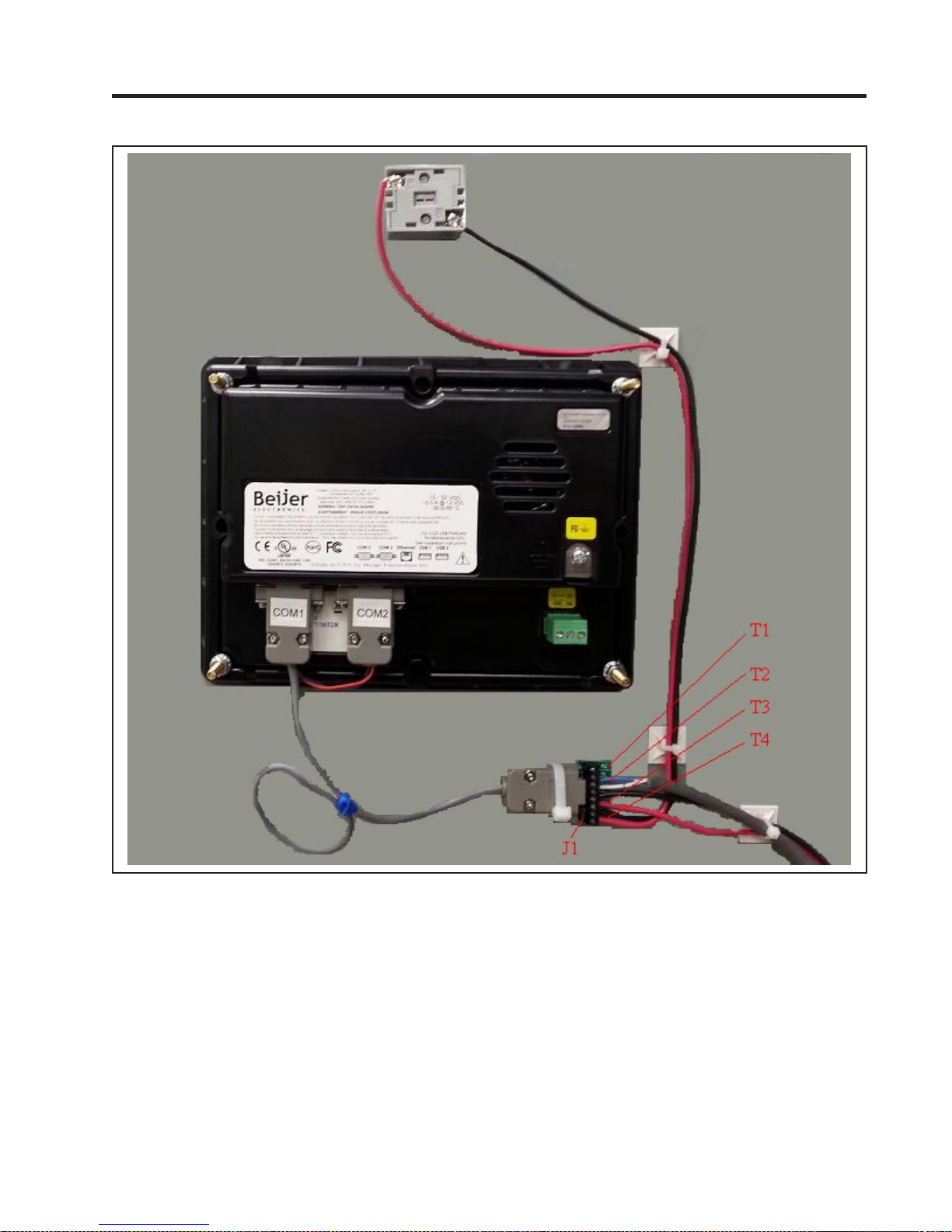
MASTER
Figure 5.13 MR100 for Windows CE Group Interface Module, Rear V iew
TRACE
Chapter 5
Operation
5.15
Page 52

MASTER
TRACE
6 Programming & Setup
Chapter 6
Programming & Setup
6.1 Getting Started
Refer to the Programming Sheet for Control Panel & Modules in the panel drawing if it is available. If not, see Figure
4.2 Sample Programming Worksheet. It shows the options
available for your Control Modules and the values entered
at the factory. Enter all changes to the factory setup under
“Factory Setup” prior to entering the changes through the
Interface Module.
For ML100/MR100 interface module, increase the value in
the DISPLA Y TIMEOUT function (msg. S3-06) so that programming is not disrupted by the display switching to the
default. Chapters 5.4 and 5.5 show the Setpoint Values
Menu. A detailed description of messages is shown in Ap-
pendix A.
For MR100 for W indows CE interface module, all setpoint
values are displayed in various edit boxes & command buttons on the Setpoint Function Page. Refer to Appendix G
for the detail operation of these boxes & buttons.
6.2 Program Enable
Each Interface Module is provided with a programming interlock to prevent tampering with setpoints. Programming
must be enabled for any values to be stored. Refer to Chap-
ter 2.3.1 for ML100/MR100, and Section 6 of Appendix G
for MR100 for W indows CE.
If the programming is disabled and [STORE]/[ENTER] is
pressed, this message is displayed:
NOT STORED
PROG DISABLED
6.3 Module List/Communication Map
For MR100 interface module, the MODULE LIST function
(msg. S3-02) identifies all the Control Modules that the
MR100 Interface Module polls or communicates with. Each
Control Module must be “Selected” for the MR100 to communicate with it. Any Control Module not selected will be
skipped by the SELECT HT functions (msg. M1-02, M2-02,
S1-02 & S2-02).
For MR100 for W indows CE interface module, the Communication Map panel selects all the Control Modules for communication. T o select a Control Module for communication,
simply check the check-box beside the module number.
cation would generate No Response alarm on Interface
Module if it does not exist in the network or powered down.
6.4 Heater Enable
The HEA TER ENABLED function (msg. S1-03) in ML100/
MR100 or drop-down box in MR100 for Windows CE identifies which heater circuits to control and monitor. Any heater
circuit that is “Disabled” will not have any control or monitoring and will be skipped by the SELECT HEATER function.
6.5 Example: Change the Setpoint for Heater 3-2
to 50 °C
6.5.1 Use ML100/MR100 interface module:
Press [SETPOINT] to enter the Setpoint Menu. This mes-
sage is displayed:
SEPOINTS:
OPERATING VALUES
SELECT HT: 3-2 ?
NONAME &
Press [V ALUE ñ ] or [VALUE ò ] to select heater 3-2. Press
[STORE].
Press [MESSAGE ò ] until the desired message is displayed
as shown:
HEATER SETPOINT:
55°C
&
Press [V ALUE ñ ] or [V ALUE ò ] until desired temperature is
displayed (50°C). Press [STORE].
If the value was successfully stored in the Control Module,
this message is displayed:
SETPOINT:
STORED
6.5.2 Use MR100 for Windows CE interface module:
Note: A Control Module not selected can still be fully functional without communicating with an Interface Module.
On the other hand, a Control Module selected for communi-
T ab into Setpoint Function Page. Select Module 3 & Heater
2. Use the on-screen keyboard or the increment/decrement
buttons to change the Heater Setpoint to 50°C.
6.1
Page 53

MASTERTRACE Chapter 7 Networking Modules
7 Networking Modules
7.1 RS-485 Communications in Modbus RTU
The MasterTrace™ System uses RS-485 for all serial
communications. RS-485 provides for one master
(MR100 Group or Computer Interface) and several slaves
(Control Modules) on one data highway. The
MasterTrace™ Control Modules expand this limitation by
the use of two serial ports. This allows a Control Module
to connect to two different data highways and therefore to
two masters. The Central Computer Interface has one port
per data highway, allowing communication to an
unlimited number of Control Modules. Refer to the
MasterTrace™ MC100 Operator’s Manual. Figure 7.1
indicates how the Control Modules and Interface Modules
can be networked.
7.2 RS-485 Wiring
Beldon cable 9841 or equivalent is recommended for the
RS-485 connection. It is a 2-wire, shielded, twisted pair.
From the serial port of the Interface Module, the cable is
connected to a serial port on each Control Module in
daisy-chain fashion. The total length of this daisy-chain
should not exceed 4,000 feet. A repeater can be used to
exceed this length or to create a “T” connection. The last
Control Module on the daisy-chain must be terminated.
Set the RS485-120 Jumpers to the IN position to terminate
the serial port. The RS-485 communications circuitry is
opto-isolated from the control circuitry. Do not externally
ground the shield. Refer to the figure for the appropriate
Module.
7.3 Removing a Control Module from the
Network
7.3.1 Remove from the Module List/Communication map:
From the MR100 Group Interface on the data highway,
access the MODULE LIST function (msg. S3-02), find
the Module Number to be removed and change the select
setting to NO.
From the Central Computer or MR100 for Windows CE
Group Interface on the data highway, access the
Communication Map, find the Module Number to be
removed and clear the check-box.
7.3.2 Disconnect from the Data Highway: Remove the
RS-485 cable from the serial port of the Control Module.
If the Control Module was at the end of the data highway,
change the RS485-120 jumpers setting on the new
end-of-line Control Module to the IN position.
7.4 Adding a Control Module to the Network
7.4.1 Connect to the Data Highway: Connect the Control
Module to the existing data highway by daisy-chaining
RS-485 cable to the serial port. Note that only the last
Control Module on the data highway should have its
RS485-120 jumpers set to IN.
7.4.2 Check the Module Number: Check the Programming
Sheet for Control Panel or Modules that came with the
new Control Module for the Module Number. It must be a
unique number for the data highways to which the Control
Module connects. If the Module Number is unique then
proceed to Enabling the Module. Otherwise, change the
Module Number as follows.
7.4.3 Change the Module Number: Choose a unique
Module Number for the Control Module. From the
MR100 Group Interface, use the SET MODULE
NUMBER function (msg. S3-20) to give the Control
Module a new, unique number. Note that the new Control
Module, and no other, must be in the Address Enable
Mode. The Address Enable light is on when the Control
Module is in Address Enable Mode. Refer to Chapter
5.1.2.
For the Central Computer or MR100 for Windows CE
Group Interface, tap into the Module Commissioning
/Addressing Function Page and use the Set Module
Number option to give the Control Module a new, unique
number.
7.4.4 Add to the Module List/Communication map: From
the MR100 Group Interface, access the MODULE LIST
function (msg. S3-02), find the Module Number of the
Control Module to be added and change the select setting
to YES.
From the Central Computer or MR100 for Windows CE
Group Interface, access the Communication Map, find the
Module Number to be added and check the check-box.
7.4.5 Program the Module: Set the HEATER ENABLE
setting to YES for each circuit that is used on the Control
Module, and then enter the setpoints and configuration as
required.
7.5 Communication with Third Party Equipment
As indicated in Figure 7.1, any third party equipment,
such as PLC or automation system, can join MasterTrace
communication network through its Modbus RTU
supported RS485 serial port/link and acts as a master to
gather data from MasterTrace™ control modules. The
popular PLCs such as Micro820 from Allen-Bradley and
M221 from Modicon have been proved to be successful
masters. For a third party equipment to act as a master in
MasterTrace communication network, MasterTrace
Modbus registers must be programmed into the equipment.
The MasterTrace Modbus Communication Protocol,
which details the Modbus registers map and data
structures in MasterTrace Modbus communication, is
7.1
Page 54
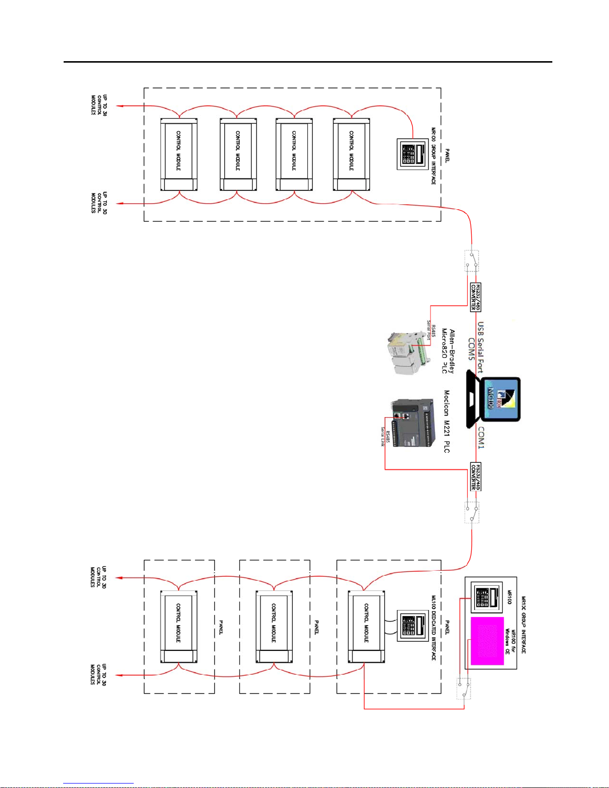
MASTERTRACE Chapter 7 Networking Modules
Figure 7.1 MASTERTRACE System Network
7.2
Page 55
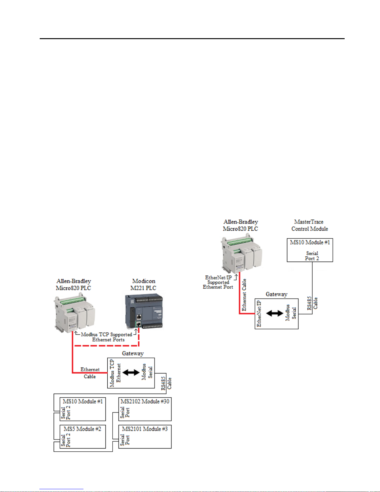
MASTERTRACE Chapter 7 Networking Modules
available from the factory upon request. Programming the
Modbus registers and software to extract data from the
registers should be done by someone familiar with the
third party equipment.
7.6 Baud Rate
The communication baud rate determines how fast data is
sent along the data highway. Baud rates available are 600,
1200, 2400, 4800 and 9600 bits per second. The default
baud rate is 1200. Each device on the network must be set
at the same baud rate in order to communicate. The user
may increase the baud rate but noise immunity, with long
cable lengths, is reduced. When changing baud rate
through an MR100 or MR100 for Windows CE Group
Intreface, change the baud rate of each control module
connected to the data highway first and the Group
Intreface last. Be sure to select the correct serial port on
the control module.
7.7 Ethernet Communication in Modbus TCP and
MasterTrace Heat Tracing Panel Option “ETH”
In Figure 7.2, Ethernet communication in Modbus TCP is
added to MasterTrace heat tracing panel by Modbus TCP
Ethernet to Modbus Serial gateway. The gateway (ex.
GC-NET485-MB from Grid Connect) is a Modbus RS485
serial to Modbus TCP Ethernet converter. The RS485 side
can connect to the serial port 2 of MasterTrace control
modules over long distances (up to 4000 feet). The
Figure 7.2 Modbus TCP Ethernet Communication
Ethernet side converts the serial Modbus data stream to
Modbus TCP Ethernet packets.
Connect a PLC or Automation system to the gateway
through its Ethernet port and use it as the Master in the
network. You can program the Master according to
MasterTrace Modbus Communication Protocol to
write/read data to/from MasterTrace control modules over
Ethernet from anywhere in the plant as long as the
Ethernet port on the PLC or Automation system is
Modbus TCP supported and is assigned to an IP address
that is different to the IP addresses of the gateway and
other devices in the Ethernet network. Most of PLCs and
Automation systems such as Micro820 from
Allen-Bradley and M221 from Modicon do have this kind
of Ethernet port as built-in.
ETH, an additional option, has been added to the
MasterTrace heat tracing panel model codes to allow
customers to purchase Nextron panels with Ethernet
communication capability. Refer to Chapter 3 .4 for Model
Codes for Control Panels.
Figure 7.3 EtherNet/IP Communication
7.8 Ethernet Communication in EtherNet/IP
In Figure 7.3, Ethernet communication in EtherNet/IP is
added to MasterTrace heat tracing control module by
EtherNet/IP to Modbus Serial gateway. The gateway (ex.
GC-NET485-EIP-MB from Grid Connect) has 2 sides.
The Modbus Serial side connects to a single MasterTrace
control module through RS485 cable and acts as a master
in the Modbus RTU communication network. The
EtherNet/IP side connects to a PLC’s EtherNet/IP
supported Ethernet port via Ethernet cable and functions
as a server in the EtherNet/IP communication network.
With Modbus master and EtherNet/IP slave software
built-in, the gateway regularly polls Modbus registers’
data from the MasterTrace control module once it is
configured by any EtherNet/IP configuration tool. The
polled Modbus data is then translated into EtherNet/IP
assembly data which can be read in standard EtherNet/IP
7.3
Page 56
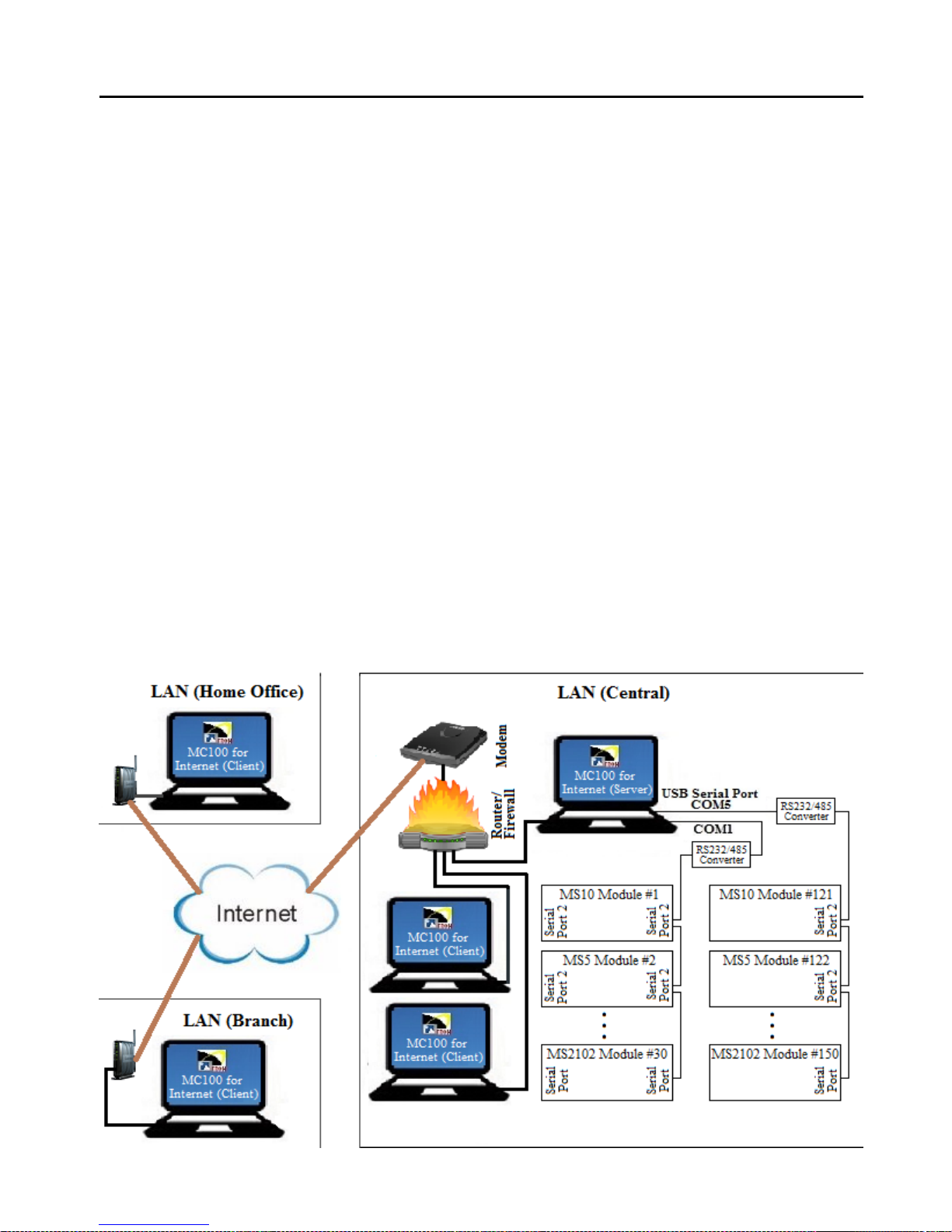
MASTERTRACE Chapter 7 Networking Modules
explicit messaging by a PLC (ex. Micro820 from
Allen-Bradley) acting as a client in the EtherNet/IP
communication network.
There is a limitation in this type of Ethernet
communication. A PLC or Automation system can only
communicate to one Modbus slave. In other words, it adds
Ethernet communication capability to a MasterTrace
control module, not to a MasterTrace heat tracing panel.
7.9 MC100 for Internet
MC100 for Internet is designed for plant wide monitoring
and programming of MasterTrace control modules using a
standard PC running in Windows operating system. It
communicates to control modules through RS485 serial
link with facilities for bringing data on any part of
network to the desk top and controlling the operation of
heat tracing controllers remotely. With its server/client
Internet communication capability, cross continent control
and maintenance of heat tracing systems are realities.
Figure 7.4 shows the overall network connections of
MC100 for Internet.
MC100 internet communication network consists of one
server (MC100 server) and one or more clients (MC100
client).
A MC100 server is a MC100 for Internet software
configured as the server in the MC100 internet
communication network. It must be installed on the PC
Figure 7.4 MC100 for Internet Network Connections
that is the master in the RS485 communication network.
Its functionalities are two-folded. First, it has the physical
links with all heat tracing controllers and uses these links
to query data from the controllers in the RS485 network.
Secondly, it is the server in the internet communication
network, and upon request, it will pass all information
obtained from the RS485 network to its clients over the
world.
A MC100 client is a MC100 for Internet software
installed on a PC and configured as a client in the MC100
internet communication network. Even though it has no
physical links with any heat-tracing controllers, it can
monitor and control the operation of any controllers
through the MC100 server.
For a MC100 client to communicate to the server, the
Server IP address in its Internet Setup panel must be set
correctly. (1) If the MC100 server and client are located in
the same LAN (Local Area Network), the Server IP is the
LAN IP Address of the MC100 server computer. (2) If
the MC100 server and client are located in separated
LANs, the Server IP is the WAN IP Address of the
LAN which the MC100 server PC belongs to. In this case,
since the MC100 server computer is connecting to the
client computer through a router or firewall, users of the
server computer must ask their network administrator to
configure the Port Forwarding (to the MC100 server
computer) function on Port 5000 of the router.
7.4
Page 57
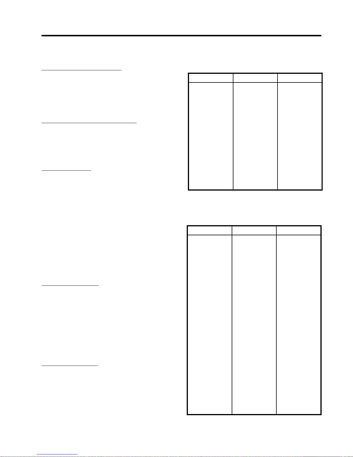
MASTER
TRACE
8 Service & Testing
Chapter 8
Service & Testing
8.1 Troubleshooting Hint s
8.1.1 Disable Advanced Functions: When you are trying to
determine the problem on a heater circuit it can be helpful to
turn off the advanced functions for the heater circuit or
control module being checked. These include PROPORTIONAL CONTROL (msg. S2-05), POWER LIMIT CURRENT (msg. S1-19), TRACECHECK™ CYCLE (msg. S1-22)
and ST AGGER ST ART (msg. S3-10).
8.1.2 Use MANUAL HEATER Function: It may be necessary to force the heater circuit on to take measurements.
The MANUAL HEATER function (msg. S4-02) is provided
for this purpose and eliminates the need to change the heater
setpoint to force the heater circuit on.
8.2 Field T ests
8.2.1 RTD Input Test: The R TD input can be tested by connecting a known resistance of sufficient accuracy . A decade
Resistance Box or RTD Simulator is recommended. Disconnect the RTD(s) from the control module ensuring that the
leads are adequately labeled. Connect the Resistance Box
as shown in Figure 8.3. If the module has dual R TD inputs,
set the RTD MODE function (msg. S2-08) to “2 R TDs, averaged” and connect the second RTD input in parallel with
the first as shown. Select a temperature from Figure 8.1 or
Figure 8.2 that is close to the maintain temperature and set
the Resistance Box to the equivalent resistance. The displayed HEA TER CONTROL TEMPERATURE (msg. M1-04)
should equal the selected temperature within the accuracy
of the devices used. If there is a significant discrepancy,
return the Control Module to the factory for repair. When
testing is complete, reconnect the RTD(s).
8.2.2 Current Input Test: The current inputs can be tested
by using an ammeter. A clamp-on CT is recommended to
eliminate the need to disconnect the heater leads. T o measure phase current, place the clamp-on CT around a single
heater phase wire. For three-phase loads, this means around
three phase conductors and a neutral (for 4-wire systems).
Using the Interface Module, display the current being measured. The displayed current should equal the measured current within the accuracy of the devices used. If there is a
significant discrepancy, return the Control Module to the
factory for calibration.
8.2.3 Alarm Output Test: If an external alarm signal is integral to the system operation, the alarm output should be
tested regularly. The alarm output on each control module
is tested using the MANUAL ALARM function (msg. S4-
03). The alarm output on the MR100 Interface Module is
tested using the MANUAL SYSTEM ALARM function
(msg. S4-04). There is no MANUAL SYSTEM ALARM function on MR100 for W indows CE Interface Module. Its alarm
Figure 8.1 Resistance versus Temperature in °C
(DIN 43760 RTD)
C°)smho(RC°)smho(RC°)smho(R
04-72.480898.03100248.571
03-22.880907.43101215.971
02-61.2900105.83102271.381
01-90.6901192.24103228.681
000.00102160.64104264.091
0109.30103128.94105280.491
0297.70104185.35106296.791
0376.11105123.75107203.102
0446.51106140.16108288.402
0593.91107167.46109264.802
0642.32108174.86100330.212
0770.72109161.271
Figure 8.2 Resistance versus Temperature in °F
(DIN 43760 RTD)
F°)smho(RF°)smho(RF°)smho(R
04-72.4806105.72106392.961
03-74.6807126.92107343.171
02-66.8808147.13108393.371
01-58.0909168.33109334.571
030.3900279.53100484.771
0122.5901280.83101415.971
0293.7902281.04102455.181
0375.9903292.24103485.381
0447.10104283.44104416.581
0509.30105284.64105436.781
0660.60106275.84106456.981
0722.80107266.05107476.191
0883.01108247.25108486.391
0935.21109228.45109496.591
00186.41100309.65100596.791
01138.61101379.851
02179.81102340.161
03101.12103311.361
04142.32104371.561
05173.52105332.761
8.1
Page 58
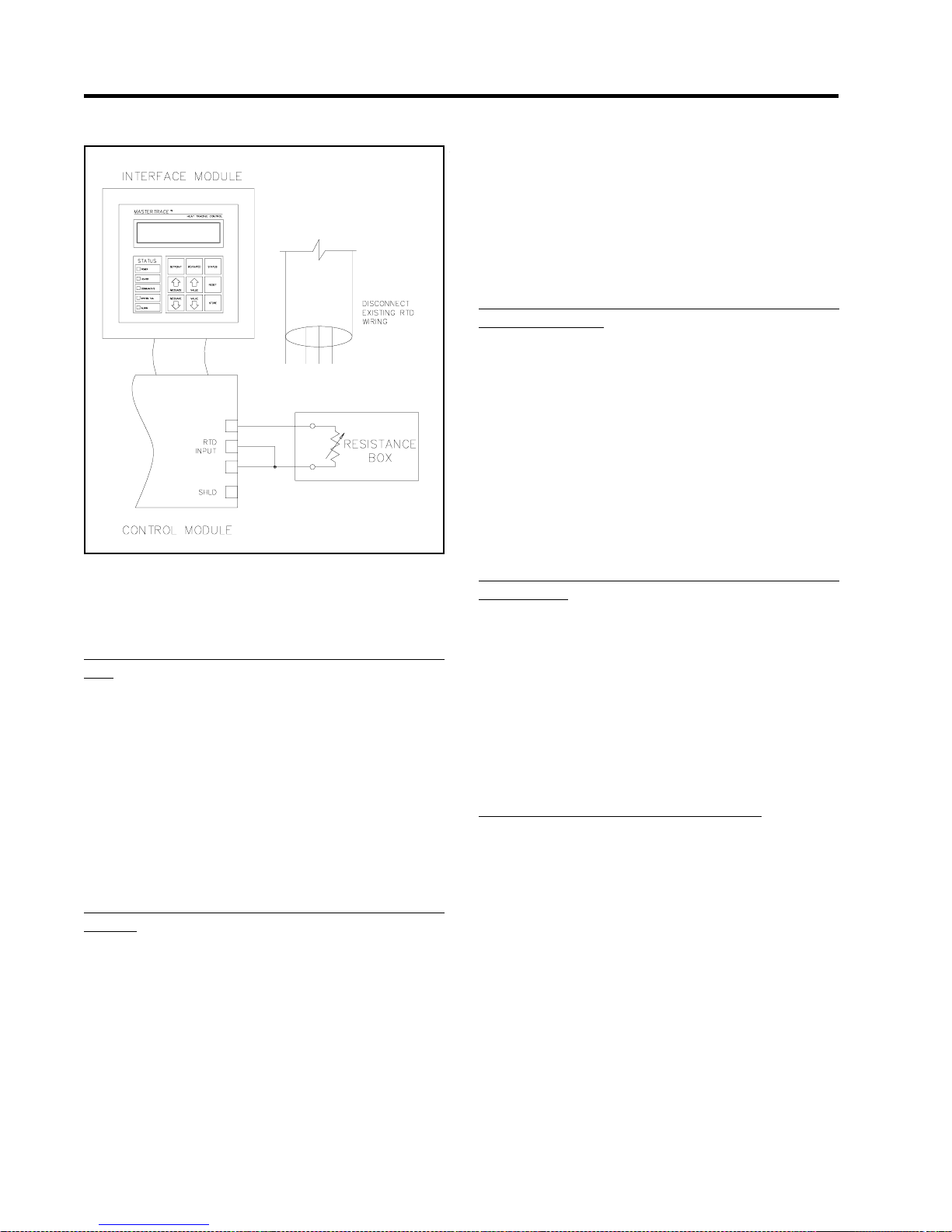
MASTER
TRACE Chapter 8
Service & Testing
Figure 8.3 RTD Input Test
output can be tested by generating a real alarm in the Control Module.
8.3 Field Repairs
8.3.1 Replacing a Switch on MS-1DIN2 & MS-2DIN2 Modules: These modules use mechanical relays mounted inside
the Control Module. Refer to Figure 5.1 in completing the
following steps.
Turn off power to the Control Module and all affected heater
circuits.
• Locate the failed relay and remove the six quick disconnects.
• Remove the two #6-32 screws that secure the relay and
remove the failed relay.
• Use Nextron part number 0403-0002 (Potter &
Brumfield # T92S7A22-120) for replacement relay .
• Repeat above steps in reverse order to assemble.
8.3.2 Replacing a Switch on MS-5ADIN2 & MS-10ADIN2
Module: These modules use mechanical relays mounted
inside the Control Module. Refer to Figure 5.5 in completing the following steps.
• Turn off power to the Control Module and all affected
heater circuits.
• Remove the six #6-32 machine screws (labeled “A”)
from the RTD board.
• Lift off the RTD board and disconnect the ribbon cable
from the RTD board. The RTD connections do not need
to be removed.
• Remove the four #6-32 machine screws (labeled “B”) that
hold the Power Board housing and remove the housing.
• Locate the failed relay and remove the six quick disconnects.
• Remove the top #6-32 screw and Nylock nut that secure
the relay and remove the failed relay.
• Use Nextron part number 0403-0002 (Potter & Brumfield
# T92S7A22-120) for replacement relay .
• Repeat above steps in reverse order to assemble.
8.3.3 Replacing a Switch on a Module with SXH, DXH or
TXH Switch Types: These modules use solid-state relays
mounted external to the Control Module. Complete the following steps.
• Turn off power to the affected heater circuits.
• Locate the failed relay and disconnect the wires (ensure
that all wires are adequately labeled).
• Remove the two #6-32 screws that secure the relay, remove the failed relay and discard the thermal conductive
pad.
• Use Nextron part number 1007-0003 (Berquist # Q2-101)
for replacement thermal conductive pad. Use Nextron part
number from the panel drawing for replacement relay .
• Repeat above steps in reverse order to assemble.
8.3.4 Replacing a Switch on a Module with DXN or TXN
Switch Types: These modules use mechanical contactors
mounted external to the Control Module. Complete the following steps.
• Turn off power to the affected heater circuits.
• Locate the failed contactor and disconnect the wires (ensure that all wires are adequately labeled).
• Remove the four screws that secure the contactor and
remove the failed contactor.
• Use Nextron part number from the panel drawing for replacement contactor.
• Repeat above steps in reverse order to assemble.
8.3.5 Replacing a DIN Switch Type Module: Before pro-
ceeding, check that all wires connected to the module are
correctly labeled. Check that the Programming Sheet for
Control Panel or Modules correctly reflects the configuration of the module. The replacement Control Module can be
programmed before it is placed in the control panel by connecting a 120 Vac supply to its power input terminals and
following the steps in Chapter 6. Complete the following
steps.
• Turn off power to the Control Module and all affected
heater circuits.
• Disconnect all wires to the Control Module. Refer to Fig-
ure 5.1or Figure 5.5/5.6/5.7 as appropriate.
• Remove the four Nylock nuts that secure the Control
Module to the back plate and remove the module.
• Repeat the above steps in reverse order to install the new
module.
8.2
Page 59

MASTER
TRACE
Chapter 8
Service & Testing
• If the new module has not been programmed according
to the Programming Sheet for Control Panel or
Modules, then complete at this time following the steps
in Chapter 6.
8.3.6 Replacing an MS-1 or MS-2 External Switching Mod-
ule: Before proceeding, check that all wires connected to
the module are correctly labeled. Check that the Programming Sheet for Control Panel or Modules correctly reflects
the configuration of the module. The replacement control
module can be programmed before it is placed in the control
panel by connecting a 120 Vac supply to its power input
terminals and following the steps in Chapter 6. Complete
the following steps.
• Turn off power to the Control Module and all affected
heater circuits.
• Disconnect all wires to the Control Module. Refer to Fig-
ure5.2 or Figure 5.3.
• Remove the four Nylock nuts that secure the Control
Module to the back plate and remove the module.
• Repeat the above steps in reverse order to install the new
module.
• If the new module has not been programmed according
to the Programming Sheet for Control Panel or Modules,
then complete at this time following the steps in Chapter
6.
8.3.7 Replacing an MS-5 or MS-10 Module with External
Switching: Before proceeding, check that all wires connected
to the module are correctly labeled. Check that the Programming Sheet for Control Panel or Modules correctly reflects
the configuration of the module. The replacement control
module can be programmed before it is placed in the control
panel by connecting a 120 Vac supply to its power input
terminals and following the steps in Chapter 6.
Complete the following steps.
• Turn off power to the Control Module and all affected
heater circuits.
• Disconnect all wires from the Control Module. Refer to
Figure 5.4.
• Remove the four Nylock nuts that secure the Control
Module to the back plate and remove the module.
• Repeat the above steps in reverse order to install the new
module.
• If the new module has not been programmed according
to the Programming Sheet for Control Panel or Modules,
then complete at this time following the steps in Chapter
6.
8.3.8 Replacing the ML100 Dedicated Interface Circuit Board
Assembly or Keypad: Before proceeding, check that all wires
connected to the module are correctly labeled. Complete
the following steps.
• Turn off power to the Control Module which is connected
to the ML100.
• Disconnect the ribbon cable from the Interface Module.
• Remove the four Nylock nuts, labeled “A” in Figure 5.9
that secure the Interface Circuit Board Assembly.
• Disconnect the ribbon cable connector to the Keypad
and remove the Interface Circuit Board Assembly .
• Replace the ML100 Dedicated Interface Circuit Board
Assembly with Nextron part number 1303-0002_2.
• T o replace the Interface Keypad, insert a small blade screwdriver between the bezel and a corner of the keypad as
shown in Figure 5.8. Pry the Keypad up and pull off.
Clean any residual adhesive with a solvent. Replace with
Nextron part number 1002-0001_1. Remove the adhesive
backing from the Keypad, insert the ribbon cable through
the slot and press the Keypad into place.
• Repeat the above steps in reverse order to complete the
installation.
8.3.9 Replacing an MR100 Group Interface Circuit Board
Assembly or Keypad: Before proceeding, check that all wires
connected to the module are correctly labeled. Check that
the Programming Sheet for Control Panel or Modules correctly reflects the selected modules. Complete the following
steps.
• Turn off power to the Interface Module.
• Disconnect all wires from the Interface Module.
• Remove the four #6-32 machine screws, labeled “A1” in
Figure 5.10 that secure the Interface Module housing
and remove the housing.
• Remove the four Nylock nuts, labeled “A1” in Figure
5.11 that secure the Interface Circuit Board Assembly.
• Disconnect the ribbon cable connector to the Keypad
and remove the Interface Circuit Board Assembly .
• To replace the MR100 Group Interface Circuit Board Assembly use Nextron part number 1304-0001_5.
• T o replace the Interface Keypad, insert a small blade screwdriver between the bezel and a corner of the keypad as
shown in Figure 5.8. Pry the Keypad up and pull off.
Clean any residual adhesive with a solvent. Replace with
Nextron part number 1002-0001_1. Remove the backing
from the Keypad, insert the ribbon cable through the slot
and press the Keypad into place.
• Repeat the above steps in reverse order to complete the
installation.
• Program the selected Control Modules for communications.
8.3.10 Replacing an MR100 for Windows CE Group Inter-
face Module: As shown in Figure 5.13 in Chapter 5 &
Figure Serial Communication 2 in Appendix D, a complete
MR100 for W indows CE Group Interface Module consists
of these three components: (1) Programmed QTERM-A7
touch screen terminal (Nextron part number 9003-0062_1);
(2) Cable for QTERM-A7 (Nextron part number 9003-0063);
(3) 12Vdc power supply (Nextron part number 0507-0002).
8.3
Page 60

MASTER
Before proceeding, check that all wires connected to the
module are correctly labeled. Check that the Programming
Sheet for Control Panel or Modules correctly reflects the
selected modules. Complete the following steps.
• Turn off power to the Interface Module.
• Disconnect power wires to the 12Vdc power supply.
• To replace the Programmed QTERM-A7 touch screen
terminal, remove the terminal from the panel enclosure,
then replaced with Nextron part number 9003-0062_1.
• To replace the Cable for QTERM-A7, remove the cable
by disconnecting all its wire connections, then replaced
with Nextron part number 9003-0063.
• To replace the 12Vdc power supply, remove the power
supply by disconnecting all its wire connections, then
replaced with Nextron part number 0507-0002.
TRACE Chapter 8
Service & Testing
8.4
Page 61

MASTER
TRACE
Appendix A Display Message Details - Setpoints
Setpoints: Operating V alues
Appendix A
Details - Setpoints
Display Message
SETPOINTS:
OPERATING VALUES
SELECT HT: 1-1 ?
NONAME &
HEATER ENABLED?
yes ?
MESSAGE NO: S1-01 APPLIES TO: Interface Module
DEF AULT VALUE: N/A VALUE RANGE: N/A
DISPLA Y MODE: All RESTRICTIONS: None
This message displays the name of the sub-menu when entered.
MESSAGE NO: S1-02 APPLIES TO: Interface Module
DEF AULT VALUE:Selected Htr VALUE RANGE: Set by MODULE RANGE
function
DISPLA Y MODE: All RESTRICTIONS: None
This function selects the heater circuit. Each heater circuit has a unique two-part
Heater Number. The first part is the Module Number and the second part is the
heater circuit within the Control Module. Press [V ALUE ñ] or [VALUE ò] and then
press [STORE] to select a heater circuit. For convenience, and to reduce human
error, the Heater Name is also displayed.
MESSAGE NO: S1-03 APPLIES TO: Selected Heater
DEF AULT VALUE: no V ALUE RANGE: yes, no
DISPLA Y MODE: Advanced RESTRICTIONS: None
This function enables control and monitoring for the heater circuit. Setpoints and
measured value messages cannot be accessed unless the heater is enabled. Select
“no” if the circuit is not used.
HEATER SETPOINT:
150°C ?
LOW TEMPERA TURE
ALARM: 120°C?
MESSAGE NO: S1-04 APPLIES TO: Selected Heater
DEF AULT V ALUE: 20 °C V ALUE RANGE: 0 to 500 °C, none, off
68 °F 32 to 932 °F , none, off
DISPLA Y MODE: All RESTRICTIONS: None
This function sets the maintain temperature. For on-off control, the circuit is
energised if the Heater Control Temperature is less than the Heater Setpoint minus
the DEADBAND. The circuit is de-energised if the Heater Control T emperature is
greater than the Heater Setpoint plus the DEADBAND. Both PROPOR TIONAL
CONTROL and POWER LIMIT affect heater switching. If the Heater Setpoint is set
to “none”, the heater circuit will have temperature monitoring with no temperature
control. If the Heater Setpoint is set to “off”, the heater circuit will have no temperature monitoring or control.
MESSAGE NO: S1-05 APPLIES TO: Selected Heater
DEF AULT V ALUE: 5°C V ALUE RANGE: -50 to 500 °C, off
41°F -58 to 932 °F , off
DISPLA Y MODE: All RESTRICTIONS: None
This function sets the Low Temperature Alarm setpoint. It must be less than the
Heater Setpoint. To disable this alarm set the value to “off”. When the Heater
Control Temperature is less than or equal to this setpoint, the Low T emperature
Alarm is activated and a “LOW TEMPERATURE ALARM” message is added to
the System Status messages. The alarm deactivates when the temperature rises
above this alarm setpoint.
A.1
Page 62

MASTER
HIGH TEMPERA TURE
ALARM: 130°C ?
TRACE
Appendix A
Display Message
Details - Setpoints
MESSAGE NO: S1-06 APPLIES TO: Selected Heater
DEF AULT V ALUE: off V ALUE RANGE: -50 to 500 °C, off
-58 to 932 °F , off
DISPLA Y MODE: All RESTRICTIONS: None
This function sets the High Temperature Alarm setpoint. It must be gr eater than
the Heater Setpoint. To disable this alarm set the value to “off”. When the Heater
Control Temperature is greater than or equal to this setpoint, the High Temperature
Alarm is activated and a “HIGH TEMPERATURE ALARM” message is added to
the System Status messages. The alarm deactivates when the temperature falls
below this alarm setpoint.
LOW CURRENT
ALARM: 10.5A ?
A: LOW CURRENT
ALARM: 10.5A ?
MESSAGE NO: S1-07 APPLIES TO: Selected Heater
DEFAULT VALUE: off VALUE RANGE: 0.5 to 100.0 A, off
DISPLA Y MODE: All RESTRICTIONS: Single-Phase Modules
This function sets the Low Current Alarm setpoint. It must be less than the High
Current Alarm setpoint. To disable this alarm set the value to “off”. When the
Heater Current is less than or equal to this setpoint, the Low Current Alarm is
activated and a “LOW CURRENT ALARM” message is added to the System
Status messages. The alarm deactivates when the Heater Current rises above this
alarm setpoint. The value range is in 0.5 A increments. The maximum value for
internal switching Control Modules is 30 A.
Note: This setpoint is based on the heater at 100% power . If Proportional Control
or Power Limit is enabled, all current measurements will be converted to 100%
power, based on a constant resistive load, before being compared to the alarm
setpoint.
MESSAGE NO: S1-08 APPLIES TO: Selected Heater
DEF AULT V ALUE: off V ALUE RANGE: 0.5 to 100.0 A, off
DISPLA Y MODE: All RESTRICTIONS: Three-Phase Modules
This function sets the phase “A” Low Current Alarm setpoint. It must be less than
the phase “A” High Current Alarm setpoint. To disable this alarm set the value to
“off”. When the Heater Current-A is less than or equal to this setpoint, the Low
Current-A Alarm is activated and a “LOW CURRENT-A ALARM” message is
added to the System Status messages. The alarm deactivates when the Heater
Current-A rises above this alarm setpoint. The value range is in 0.5 A increments.
Note: This setpoint is based on the heater at 100% power . If Proportional Control
or Power Limit is enabled, all current measurements will be converted to 100%
power, based on a constant resistive load, before being compared to the alarm
setpoint.
B: LOW CURRENT
ALARM: 10.5A ?
MESSAGE NO: S1-09 APPLIES TO: Selected Heater
DEFAULT VALUE: off VALUE RANGE: 0.5 to 100.0 A, off
DISPLA Y MODE: All RESTRICTIONS: Three-Phase Modules
This function sets the phase “B” Low Current Alarm setpoint. It must be less than
the phase “B” High Current Alarm setpoint. To disable this alarm set the value to
“off”. When the Heater Current-B is less than or equal to this setpoint, the Low
Current-B Alarm is activated and a “LOW CURRENT-B ALARM” message is
added to the System Status messages. The alarm deactivates when the Heater
Current-B rises above this alarm setpoint. The value range is in 0.5 A increments.
Note: This setpoint is based on the heater at 100% power. If Proportional Control
or Power Limit is enabled, all current measurements will be converted to 100%
power, based on a constant resistive load, before being compared to the alarm
setpoint.
A.2
Page 63

MASTER
TRACE
Appendix A
Details - Setpoints
Display Message
C: LOW CURRENT
ALARM: 10.5A ?
HIGH CURRENT
ALARM: 15.0A ?
MESSAGE NO: S1-10 APPLIES TO: Selected Heater
DEFAULT VALUE: off VALUE RANGE: 0.5 to 100.0 A, off
DISPLA Y MODE: All RESTRICTIONS: Three-Phase Modules
This function sets the phase “C” Low Current Alarm setpoint. It must be less than
the phase “C” High Current Alarm setpoint. To disable this alarm set the value to
“off”. When the Heater Current-C is less than or equal to this setpoint, the Low
Current-C Alarm is activated and a “LOW CURRENT-C ALARM” message is
added to the System Status messages. The alarm deactivates when the Heater
Current-C rises above this alarm setpoint. The value range is in 0.5 A increments.
Note: This setpoint is based on the heater at 100% power . If Proportional Control
or Power Limit is enabled, all current measurements will be converted to 100%
power, based on a constant resistive load, before being compared to the alarm
setpoint.
MESSAGE NO: S1-11 APPLIES TO: Selected Heater
DEFAULT VALUE: off VALUE RANGE: 0.5 to 100.0 A, off
DISPLA Y MODE: All RESTRICTIONS: Single-Phase Modules
This function sets the High Current Alarm setpoint. It must be greater than the
Low Current Alarm setpoint. To disable this alarm set the value to “off”. When the
Heater Current is greater than or equal to this setpoint, the High Current Alarm is
activated and a “HIGH CURRENT ALARM” message is added to the System
Status messages. The alarm deactivates when the Heater Current falls below this
alarm setpoint. The value range is in 0.5 A increments. The maximum value for
internal switching Control Modules is 30 A.
A: HIGH CURRENT
ALARM: 15.0A ?
B: HIGH CURRENT
ALARM: 15.0A ?
C: HIGH CURRENT
ALARM: 15.0A ?
MESSAGE NO: S1-12 APPLIES TO: Selected Heater
DEFAULT VALUE: off VALUE RANGE: 0.5 to 100.0 A, off
DISPLA Y MODE: All RESTRICTIONS: Three-Phase Modules
This function sets the phase “A” High Current Alarm setpoint. It must be greater
than the Low Current-A Alarm setpoint. To disable this alarm set the value to
“off”. When the Heater Current-A is greater than or equal to this setpoint, the High
Current-A Alarm is activated and a “HIGH CURRENT-A ALARM” message is
added to the System Status messages. The alarm deactivates when the Heater
Current-A falls below this alarm setpoint. The value range is in 0.5 A increments.
MESSAGE NO: S1-13 APPLIES TO: Selected Heater
DEFAULT VALUE: off VALUE RANGE: 0.5 to 100.0 A, off
DISPLA Y MODE: All RESTRICTIONS: Three-Phase Modules
This function sets the phase “B” High Current Alarm setpoint. It must be greater
than the Low Current-B Alarm setpoint. To disable this alarm set the value to
“off”. When the Heater Current-B is greater than or equal to this setpoint, the High
Current-B Alarm is activated and a “HIGH CURRENT-B ALARM” message is
added to the System Status messages. The alarm deactivates when the Heater
Current-B falls below this alarm setpoint. The value range is in 0.5 A increments.
MESSAGE NO: S1-14 APPLIES TO: Selected Heater
DEF AULT V ALUE: off V ALUE RANGE: 0.5 to 100.0 A, off
DISPLA Y MODE: All RESTRICTIONS: Three-Phase Modules
This function sets the phase “C” High Current Alarm setpoint. It must be greater
than the Low Current-C Alarm setpoint. To disable this alarm set the value to
“off”. When the Heater Current-C is greater than or equal to this setpoint, the High
Current-C Alarm is activated and a “HIGH CURRENT-C ALARM” message is
added to the System Status messages. The alarm deactivates when the Heater
Current-C falls below this alarm setpoint. The value range is in 0.5 A increments.
A.3
Page 64

MASTER
HIGH CURRENT
TRIP: off ?
A: HIGH CURRENT
TRIP: off ?
TRACE
Appendix A
Display Message
Details - Setpoints
MESSAGE NO: S1-15 APPLIES TO: Selected Heater
DEFAULT VALUE: off VALUE RANGE: 0.5 to 100.0 A, off
DISPLA Y MODE: Advanced RESTRICTIONS: Single-Phase Modules
This function sets the High Current Trip setpoint. It must be greater than the Low
Current Alarm and the High Current Alarm setpoints. To disable this trip function
set the value to “off”. When the Heater Current is greater than or equal to this
setpoint, the heater circuit is opened, a High Current Trip Alarm is activated and a
“HIGH CURRENT TRIP” message is added to the System Status messages. This
is a latching alarm. When the cause of the alarm has been corrected, locate the
alarm message in the Status Menu and press [RESET]. The value range is in 0.5 A
increments. The maximum value for internal switching Control Modules is 30 A.
MESSAGE NO: S1-16 APPLIES TO: Selected Heater
DEF AULT V ALUE: off V ALUE RANGE: 0.5 to 100.0 A, off
DISPLA Y MODE: Advanced RESTRICTIONS: Three-Phase Modules
This function sets the phase “A” High Current Trip setpoint. It must be greater
than the Low Current-A Alarm and the High Current-A Alarm setpoints. To
disable this trip function set the value to “off”. When the Heater Current-A is
greater than or equal to this setpoint, the heater circuit is opened, a High Current-A
Trip Alarm is activated and a “HIGH CURRENT -A TRIP” message is added to the
System Status messages. This is a latching alarm. When the cause of the alarm has
been corrected, locate the alarm message in the Status Menu and press [RESET].
The value range is in 0.5 A increments.
B: HIGH CURRENT
TRIP: off ?
C: HIGH CURRENT
TRIP: off ?
MESSAGE NO: S1-17 APPLIES TO: Selected Heater
DEF AULT V ALUE: off V ALUE RANGE: 0.5 to 100.0 A, off
DISPLA Y MODE: Advanced RESTRICTIONS: Three-Phase Modules
This function sets the phase “B” High Current Trip setpoint. It must be greater
than the Low Current-B Alarm and the High Current-B Alarm setpoints. To
disable this trip function set the value to “off”. When the Heater Current-B is
greater than or equal to this setpoint, the heater circuit is opened, a High Current-B
Trip Alarm is activated and a “HIGH CURRENT -B TRIP” message is added to the
System Status messages. This is a latching alarm. When the cause of the alarm has
been corrected, locate the alarm message in the Status Menu and press [RESET].
The value range is in 0.5 A increments.
MESSAGE NO: S1-18 APPLIES TO: Selected Heater
DEFAULT VALUE: off VALUE RANGE: 0.5 to 100.0 A, off
DISPLA Y MODE: Advanced RESTRICTIONS: Three-Phase Modules Only
This function sets the phase “C” High Current Trip setpoint. It must be greater
than the Low Current-C Alarm and the High Current-C Alarm setpoints. To
disable this trip function set the value to “off”. When the Heater Current-C is
greater than or equal to this setpoint, the heater circuit is opened, a High Current-C
Trip Alarm is activated and a “HIGH CURRENT-C TRIP” message is added to the
System Status messages. This is a latching alarm. When the cause of the alarm has
been corrected, locate the alarm message in the Status Menu and press
[RESET].The value range is in 0.5 A increments.
A.4
Page 65

MASTER
TRACE
Appendix A
Details - Setpoints
Display Message
POWER LIMIT CURRENT:
20.5A ?
GROUND FAUL T
TRIP: 100mA ?
MESSAGE NO: S1-19 APPLIES TO: Selected Heater
DEFAULT VALUE: off VALUE RANGE: 0.5 to 100.0 A, off
DISPLA Y MODE: Advanced RESTRICTIONS: Solid-State Modules Only
This function sets the maximum average current that flows in the heater circuit. It
is useful for limiting the inrush current of self regulating cable or to reducing the
power output of constant wattage heaters. Set the value below the breaker rating or
to the maximum power desired (W attage = Heater Voltage x Power Limit value).
The value range is in 0.5 A increments.
MESSAGE NO: S1-20 APPLIES TO: Selected Heater
DEFAULT VALUE: 50 mA VALUE RANGE: 10 to 1000 mA, off
DISPLA Y MODE: Advanced RESTRICTIONS: None
This function sets the Ground Fault Trip setpoint. It must be greater than the
Ground Fault Alarm setpoint. To disable this trip alarm set the value to “of f”.
When the Ground Fault Current is greater than or equal to this setpoint, the heater
circuit is opened, the Ground Fault Trip Alarm is activated and a “GROUND
FAULT TRIP” message is added to the System Status messages. This is a latching
alarm. When the cause of the alarm has been corrected, locate the alarm message in
the Status Menu and press [RESET]. The value range is in 5 mA increments.
GROUND FAUL T
ALARM: 20mA ?
TRACECHECK CYCLE
TIME: 4 hours ?
MESSAGE NO: S1-21 APPLIES TO: Selected Heater
DEFAULT VALUE: 25 mA VALUE RANGE: 10 to 1000 mA, off
DISPLA Y MODE: All RESTRICTIONS: None
This function sets the Ground Fault Alarm setpoint. It must be less than the
Ground Fault Trip setpoint. To disable this alarm set the value to “off”. When the
Ground Fault Current is greater than or equal to this setpoint, the Ground Fault
Alarm is activated and a “GROUND FAULT ALARM” message is added to the
System Status messages. The alarm deactivates when the Ground Fault Current
falls below this alarm setpoint. The value range is in 5 mA increments.
MESSAGE NO: S1-22 APPLIES TO: Selected Heater
DEF AULT V ALUE: off V ALUE RANGE: 1 to 24 hours, off
DISPLA Y MODE: Advanced RESTRICTIONS: None
This function sets the frequency at which TraceCheck™ is activated.
TraceCheck™ is a feature that exercises the system by automatically applying
power to the heater for a period defined by TRACECHECK HTR ON TIME. If an
alarm condition is detected during this period, then the TraceCheck™ Alarm is
activated and a “ALARM DURING TRACECHECK” message is added to the
System Status messages If a ground fault is detected, the heater circuit is opened.
This is a latching alarm. T o clear the alarm, locate the alarm message in the S tatus
Menu and press [RESET]. To disable this feature set the value to “off”.
TraceCheck™ decreases maintenance by providing an early warning of problems
that would otherwise go undetected until the heater was needed.
A.5
Page 66

MASTER
TRACE
Appendix A
Details - Setpoints
Display Message
TRACECHECK HTR ON
TIME: 0.5 min ?
HEATER VOL TAGE:
120 V ?
LOW VOLT AGE
ALARM: 100 V ?
MESSAGE NO: S1-23 APPLIES TO: Selected Heater
DEF AULT V ALUE: 0.5 min V ALUE RANGE: 0.5 to 15 min
DISPLA Y MODE: Advanced RESTRICTIONS: none
This functions sets the heater on time period (in minute) when tracecheck is
activated.
MESSAGE NO: S1-24 APPLIES TO: Selected Heater
DEF AULT V ALUE: 120V V ALUE RANGE: 100 to 600 V , (measured)
DISPLA Y MODE: Advanced RESTRICTIONS: none
This functions sets the Heater Voltage. For 1-point and 2-point Control Modules
with circuits at 300 V or less, set to “measured”. Otherwise, set to the heater
supply voltage. This value is used to compute Energy Used and Energy Cost.
MESSAGE NO: S1-25 APPLIES TO: Selected Heater
DEF AULT V ALUE:off V ALUE RANGE: 0 to 300 V , off
DISPLAY MODE: Advanced RESTRICTIONS: Single Phase, 1 and 2 point
modules
This function sets the Low Voltage Alarm setpoint. To disable this alarm set the
value to “off”. When the Heater Voltage is less than or equal to this setpoint, the
Low Voltage Alarm is activated and a “LOW VOLTAGE ALARM” message is
added to the System Status messages. The alarm deactivates when the Heater
Voltage rises above this alarm setpoint.
Setpoints: Heater Setup Menu
SETPOINTS:
HEATER SETUP
SELECT HT: 1-1?
NONAME &
MESSAGE NO: S2-01 APPLIES TO: Interface Module
DEF AULT VALUE: N/A VALUE RANGE: N/A
DISPLA Y MODE: Advanced RESTRICTIONS: None
This message displays the name of the sub-menu when entered.
MESSAGE NO: S2-02 APPLIES TO: Interface Module
DEF AULT VALUE:Selected Htr VALUE RANGE: Set by MODULE RANGE
function
DISPLA Y MODE: Advanced RESTRICTIONS: None
This function selects the heater circuit. Each heater circuit has a unique two-part
Heater Number. The first part is the Module Number and the second part is the
heater circuit within the Control Module. Press [VALUE ñ] or [VALUE ò] and
then press [STORE] to select a heater circuit. For convenience and to reduce
human error, the Heater Name is also displayed.
A.6
Page 67

MASTER
TRACE
Appendix A
Details - Setpoints
Display Message
HEATER NAME:
NONAME?
MASTER OVERRIDE:
off ?
MESSAGE NO: S2-03 APPLIES TO: Selected Heater
DEF AULT V ALUE:NONAME V ALUE RANGE: 16 Alphanumeric Characters
DISPLA Y MODE: Advanced RESTRICTIONS: None
This functions sets the Heater Name. It provides a unique, identifiable tag or label
for each heater circuit. The Heater Name consists of 16 alphanumeric characters
which are entered one at a time from left to right. The cursor indicates which
character is being selected. Press [VALUEñ] or [V ALUE ò] to change the
character. Move to the next character by pressing [ST ORE]. Continue in this
fashion until all 16 characters are entered. Press [STORE] in the last character
position to save the Heater Name.
MESSAGE NO: S2-04 APPLIES TO: Selected Heater
DEF AULT VALUE: off V ALUE RANGE: on, off
DISPLA Y MODE: Advanced RESTRICTIONS: None
This feature sets the response of the heater circuit to the Control Modules Master
Override input. The Master Override input responds to a contact closure. If the
Master Override is set to “off” or the Master Override inputs are shorted, then
control of the heater circuit operates normally based on the Heater Control
T emperature and the Heater Setpoint. If the Master Override is set to “on” and the
Master Override inputs are open, then the heater circuit is opened regardless of the
Heater Control Temperature. This feature allows selected circuits to be turned off
for load shedding or for an ambient temperature override. If the Heater Setpoint is
set to “off” or “none” and the Master Override is set to “on”, then the Master
Override input will have full control over the heater circuit. It means that the heater
will be turned on if the inputs are shorted and off if the inputs are open.
PROPORTIONAL
CONTROL: off ?
DEADBAND
1C° ?
IF RTD FAILS
HEATER GOES: off ?
MESSAGE NO: S2-05 APPLIES TO: Selected Heater
DEF AULT VALUE: off V ALUE RANGE: on, off
DISPLA Y MODE: Advanced RESTRICTIONS: Solid-State Modules
This functions minimizes temperature overshoot and undershoot for tighter
temperature control. For critical temperature maintenance applications more
accurate control can be obtained by using this feature. However, the time to reach
Heater Setpoint may be longer. With Proportional Control set to “on”, as the
Heater Control Temperature approaches the Heater Setpoint, the percent duty
cycle of the heater is reduced. W ith Proportional Control set to “off”, on-off
control is used.
MESSAGE NO: S2-06 APPLIES TO: Selected Heater
DEFAULT VALUE: 1 C° VALUE RANGE: 0 to 50 C°
DISPLA Y MODE: Advanced RESTRICTIONS: Proportional Control must
be “off”
This feature sets the size of the DEADBAND for on-off control. Decreasing the
DEADBAND increases the temperature control accuracy but also increases the
heater switching frequency and wear on mechanical contacts.
MESSAGE NO: S2-07 APPLIES TO: Selected Heater
DEF AULT V ALUE: off V ALUE RANGE: on, off
DISPLA Y MODE: Advanced RESTRICTIONS: None
This function sets the heater fail-safe state. The Control Module detects if the
temperature sensor has failed. In this case it will use only the second RTD input, if
available, or it will set the heater to its fail-safe state. For freeze protection where
there is no hazard from over heating, set to “on” to prevent freeze up. Where there
is a potential hazard from over heating, set to “off”.
A.7
Page 68

MASTER
TRACE
Appendix A
Details - Setpoints
Display Message
RTD MODE:
1 RTD ?
COPY TO OTHER
HEA TERS: no ?
MESSAGE NO: S2-08 APPLIES TO: Selected Control Module
DEF AULT V ALUE: 1 RTD, V ALUE RANGE: See list below
(2RTD, backup
for MS5)
DISPLA Y MODE: Advanced RESTRICTIONS: Dual RTD Modules
This function sets how the Heater Control Temperature is derived from dual RTD
inputs as follows.
Value Heater Control Temperature
1 RTD RTD-A
RTD B HT cutoff RTD-A but less than RTD-B
2 RTDs, lowest Minimum of RTD-A & RTD-B
2 RTDs, highest Maximum of RTD-A & RTD-B
2 RTDs, averaged A verage of RTD-A & RTD-B
2 RTDs, backup RTD-A if okay, else RTD-B
When RTD B HT cutoff is selected, RTD_B temperature is compared with the
high temperature alarm. When RTD-B temperature is equal to or greater than the
high tempertaure alarm setting the heater is turned off regardless if R TD-A
temperature is less than the heater setpoint.
Note: This message applies to all heaters on the selected control module. Customer
can use “jumpering RTD A & B” method to achieve 1 RTD configuration on individual heaters even though the selected module is set to 2 RTDs mode.
MESSAGE NO: S2-09 APPLIES TO: Selected Heater
DEF AULT V ALUE: no V ALUE RANGE: yes, no
DISPLA Y MODE: Advanced RESTRICTIONS: None
This function copies all the setpoints of the selected heater to all the other heaters
in the system. The copied setpoints are: heater enabled, heater setpoint, low &
high temperature alarm, low & high current alarm, high current trip, power limit,
ground fault trip, ground fault alarm, tracecheck cycle time, tracecheck htr on time,
heater voltage, heater name, master override, proportional control, deadband,
heater fail-safe state, and manual heater.
Setpoints: System Setup Menu
SETPOINTS:
SYSTEM SETUP
MODULE LIST
MOD:1? SEL:yes ?
MESSAGE NO: S3-01 APPLIES TO: Interface Module
DEF AULT VALUE: N/A VALUE RANGE: N/A
DISPLA Y MODE: All RESTRICTIONS: None
This message displays the name of the sub-menu when entered.
MESSAGE NO: S3-02 APPLIES TO: Interface Module
DEF AULT VALUE: MOD: 1 VALUE RANGE: MOD: Set by MODULE
SEL: no RANGE
SEL: yes, no
DISPLA Y MODE: Advanced RESTRICTIONS: MR100 Interface
This function selects which Control Modules are monitored. All Control Modules
that are to be monitored from the Interface Module must have SEL set to “yes”. All
Control Modules that are not physically connected to the Interface Module must
have SEL set to “no”. With the cursor to the right of MOD choose the Module
Number by pressing [VALUE ñ] or [V ALUE ò] and then [STORE]. With the
cursor to the right of SEL select “yes” to select or “no” to deselect the Control
Module for monitoring by pressing [VALUE ñ] or [VALUE ò] and then
[STORE].
A.8
Page 69

MASTER
TRACE
Appendix A
Details - Setpoints
Display Message
MODULE RANGE
1-30 ?
DISPLA Y MODE:
advanced user ?
DEF AULT DISPLAY:
System Status ?
MESSAGE NO: S3-03 APPLIES TO: Interface Module
DEFAULT VALUE: 1-30 VALUE RANGE: 1-30, 31-60, … , 211-240,
241-254
DISPLA Y MODE: Advanced RESTRICTIONS: MR100 Interface
This function selects the range of Control Module numbers connected to this
Interface Module. All Control Modules connected to this Interface Module must
be within this range.
MESSAGE NO: S3-04 APPLIES TO: Interface Module
DEF AULT VALUE: advanced user VALUE RANGE: advanced user, normal user
DISPLA Y MODE: All RESTRICTIONS: None
This function determines what messages are displayed. If set to “advanced user”,
all messages are displayed. If set to “normal user”, only the basic messages are
displayed. Each message listed in this appendix shows the Display Mode required
to see the message. “Advanced” indicates that the display mode must be set to
“advanced user” to view the message.
MESSAGE NO: S3-05 APPLIES TO: Interface Module
DEF AULT VALUE: System status VALUE RANGE: See values below
DISPLA Y MODE: Advanced RESTRICTIONS: None
This function specifies the information that will be displayed when no key has
been pressed for the Display Timeout interval as described below.
VALUE INFORMATION DISPLAYED
System status Alarm status of all the heaters
Heater status Heater status of selected heater
Heater temp T emperature of the selected heater
Scan heater All measured values of the selected heater
Scan temps T emperatures of all enabled heaters
Scan currents Phase currents of all enabled heaters
Scan gnd faults Ground fault currents of all enabled heaters
Scan all heaters All measured values of all enabled heaters
DISPLAY TIMEOUT :
60 seconds ?
SCAN TIME:
2 seconds ?
TEMPERATURE UNITS:
Celcius ?
MESSAGE NO: S3-06 APPLIES TO: Interface Module
DEFAULT VALUE: 60 seconds VALUE RANGE: 5 to 600 s, off
DISPLA Y MODE: Advanced RESTRICTIONS: None
This function sets the length of time, from the last key press, to automatically
return to the Default Display information. To disables this function set the value to
“off”.
MESSAGE NO: S3-07 APPLIES TO: Interface Module
DEFAULT VALUE: 3 seconds VALUE RANGE: 1 to 10 seconds
DISPLA Y MODE: Advanced RESTRICTIONS: None
This function sets the length of time between the display of successive messages.
Select a value that is comfortable for the reading speed of the operator.
MESSAGE NO: S3-08 APPLIES TO: Interface Module
DEF AULT V ALUE: Celsius VALUE RANGE: Celsius, Fahrenheit
DISPLA Y MODE: Advanced RESTRICTIONS: None
This function sets the units of measure for temperature. All temperatures are
displayed in the selected units of either Celsius degrees (C°) or Fahrenheit
degrees (F°).
A.9
Page 70

MASTER
TRACE
Appendix A
Details - Setpoints
Display Message
COST PER kWh:
$0.05 ?
STAGGER START:
on ?
NUM OF AMB SENSE
HTRS: 0 ?
MESSAGE NO: S3-09 APPLIES TO: Selected Control Module
DEFAULT VALUE: $0.05 VALUE RANGE: $0.01 to $0.50
DISPLA Y MODE: Advanced RESTRICTIONS: None
This function sets the COST PER kWh. This value is used to calculate Energy
Cost.
MESSAGE NO: S3-10 APPLIES T O : Selected Control Module
DEF AULT VALUE: off V ALUE RANGE: on, off
DISPLA Y MODE: Advanced RESTRICTIONS: None
This feature staggers the power up of heater circuits to eliminate tripping of the
main breaker. For all Control Modules with this value set to “on” the following
sequence occurs at power up based on a minimum of 10 circuits. About 10% of the
heaters circuits are turned on, there is a one minute delay and then the next 10%
are turned on until all circuits are energized.
Note: Stagger Start is a module setpoint, if this setpoint is set to “on”, Stagger
Start will only be applied to the selected module. Stagger Start will not be applied
to the whole system.
MESSAGE NO: S3-11 APPLIES TO: Selected Control Module
DEF AULT V ALUE: 0 V ALUE RANGE: 0 to 10, Master 1 to 10,
Remote 1 to 10
DISPLA Y MODE: Advanced RESTRICTIONS: None
This function sets the number of ambient sense heaters for the selected control
module. Refer to Appendix E for the operation details of this message.
AMBIENT SENSING
HEA TER: None ?
AMBIENT R TD
TEMP: 5°C &
RTD BOARD:
On Board ?
MESSAGE NO: S3-12 APPLIES TO: Interface Module
DEF AULT V ALUE: None VALUE RANGE: None, HT 1-1, HT 2-1 to
HT 30-1, MR100
DISPLA Y MODE: Advanced RESTRICTIONS: MR100 Interface Module
This function sets the global ambient RTD for the heaters selected for freeze
protection applications. Refer to Appendix E for the operation details of this
message.
MESSAGE NO: S3-13 APPLIES TO: Interface Module
DEF AULT V ALUE: N/A V ALUE RANGE: -50°C to 500°C
-58°F to 932°F
DISPLA Y MODE: Advanced RESTRICTIONS: MR100 Interface Module
This read-only message appears only when the AMBIENT SENSING HEATER
(msg. S3-12) is not selected as None. The displayed value is the actual measured
temperature of the global ambient RTD sensor. If the temperature is outside the
value range, “RTD OPEN” or “R TD SHOR T” is displayed. Refer to Appendix E for
the operation details of this message.
MESSAGE NO: S3-14 APPLIES TO: Interface Module
DEF AULT V ALUE: On Board VALUE RANGE: RTD Sampler 0 to 15, On
Board, RTD Transmitter
DISPLA Y MODE: Advanced RESTRICTIONS: ML100 Interface Module
This function sets the type of RTD board used for the control module.
When the option “On Board” is selected, the control module uses the RTD board
directly mounted on itself to measure heater temperatures.
If the option “RTD Sampler x” is chosen, the control module uses the temperature
measurements from “RTD Sampler x” to control heaters. Here, x is the address of
the RTD Sampler . The R TD Sampler is an independent temperature-measurement
device and is usually located far away from the control module. The temperature
A.10
Page 71

MASTER
TRACE
Appendix A
Display Message
Details - Setpoints
measurement from the RTD Sampler is transmitted to the control module via either
RS485 cable or RF Modem.
If the option “RTD Transmitter” is selected, the control module uses the temperature
measurement signal transmitted from the RTD T ransmitters to control heaters. The
R TD Transmitter is another independent temperature-measurement device. The actual RTD sensor is to be locally wired to the RTD Transmitter . Since the transmitter
uses just two 18A WG wires to transmit its temperature measurement to the control
module in a form of 4-20mA dc current, it can be located up to 7km away from the
control module. This creates a great deal of flexibility to the RTD wiring process.
Each control point requires a dedicated RTD Transmitter for its temperature measurement. Refer to Appendix F for the operation details of RTD Sampler and RTD
Transmitter.
BAUD RATE MR100:
1200 ?
BAUD RATE 1:
1200 ?
BAUD RATE 2:
1200 ?
ALARM LIGHT MODE:
alarm: off ?
MESSAGE NO: S3-15 APPLIES TO: Interface Module
DEF AULT V ALUE: 1200 V ALUE RANGE: 600,1200,2400,4800,9600
DISPLA Y MODE: Advanced RESTRICTIONS: MR100 Interface Module
This function sets the communication baud rate for the MR100 serial port .
MESSAGE NO: S3-16 APPLIES TO: Interface Module
DEF AULT V ALUE: 1200 V ALUE RANGE: 600,1200,2400,4800,9600
DISPLA Y MODE: Advanced RESTRICTIONS: None
This function sets the communication baud rate for serial port #1 of the controller.
If the display interface is an ML100, the baud rate applies to the control module it
is connected to. If the display interface is an MR100, the baud rate applies to
serial port #1 of the module selected.
MESSAGE NO: S3-17 APPLIES TO: Interface Module
DEF AULT V ALUE: 1200 V ALUE RANGE: 600,1200,2400,4800,9600
DISPLA Y MODE: Advanced RESTRICTIONS: None
This function sets the communication baud rate for serial port #2 of the control
module that the ML100 display is connected to. If the display interface is an
MR100, the baud rate applies to serial port #2 of the module selected.
MESSAGE NO: S3-18 APPLIES TO: Interface Module
DEF AULT VALUE: alarm:off VALUE RANGE: alarm:off, alarm:on
flash/on, flash/off
DISPLA Y MODE: Advanced RESTRICTIONS: None
This function determines the response of the alarm light output to an alarm. The
alarm light output is design to drive a 12Vdc LED. If the value is set to “alarm
off”, the alarm light is on in a no alarm condition and turns off when alarms are
present. The “alarm off” setting works best with a green LED for fail-safe mode
where loss of power or a burnt out LED generates an alarm condition. Value
“alarm on”, turns the alarm light off in a no alarm condition and turns on when
alarms are present. Value “alarm flash/on” flashes the alarm light when alarms are
present and turns on the alarm light when there are no alarms. Value “alarm flash/
off” flashes the alarm light when alarms are present and turns off the alarm light
when there are no alarms.
ALARM CONT ACTS:
MECH:NC ? SS:NC ?
MESSAGE NO: S3-19 APPLIES TO: Interface Module
DEF AULT VALUE: MECH:NC V ALUE RANGE: MECH:NO SS:NO
SS:NC MECH:NO SS:NC
MECH:NC SS:NO
MECH:NC SS:NC
DISPLA Y MODE: Advanced RESTRICTIONS: None
A.11
Page 72
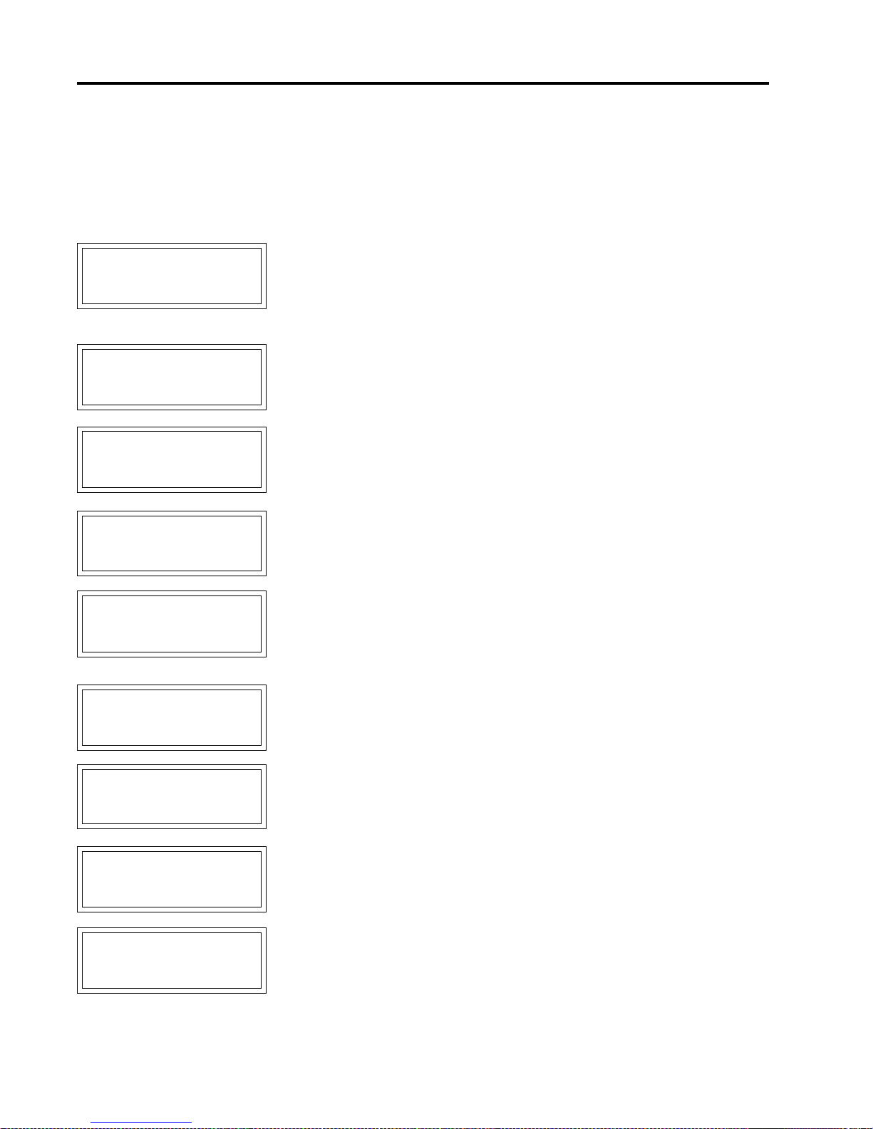
MASTER
SET MODULE
NUMBER: 1 ?
TRACE
Appendix A
Display Message
Details - Setpoints
Configures the alarm contacts for normally open (NO) or normally closed (NC).
MECH refers to the mechanical alarm contacts on terminals 6 and 7of the Control
Module and terminals 904 and 905 of the MR100 Interface Module. SS refers to
the solid-state dc alarm contacts on terminals 4 and 5 of the Control Module and
terminals 906 and 907 of the MR100 Interface Module. In NO mode, contact
closes during alarm condition. In NC mode, contacts open during alarm
condition.
MESSAGE NO: S3-20 APPLIES TO: Interface Module
DEF AULT VALUE: 1 VALUE RANGE: 1-254
DISPLAY MODE: Advanced RESTRICTIONS: ML100 Interface Module
This function changes the Module Number of the Control Module connected to
the ML100 Interface.
RESET CONTROL
MODULE? no ?
yes [STORE]
ARE YOU SURE?
no ?
yes [STORE]
SET ADDR ENABLE
ADDRESS LED ON
ô
CONT - MSSG DOWN
ABORT - RESET
ABOUT TO RESET
MODULE
ô
CONT - MSSG DOWN
ABORT - RESET
MESSAGE NO: S3-21 APPLIES TO: Address Enabled Control
Module
DEF AULT VALUE: no VALUE RANGE:yes, no
DISPLA Y MODE: Advanced RESTRICTIONS: MR100 Interface Module
This function resets all values of the Control Module which has been placed in
Address Enabled mode. Select “yes” to proceed. Select “yes” again to confirm.
This message asks you to confirm that the Control Module Address is “enabled”.
The Control Module Address light must be on. Press [MSSG ò ] to proceed. Refer
Chapter 5.1.2.
MESSAGE NO: S3-21a APPLIES TO: Address Enabled Control
Module
DEF AULT V ALUE: None VALUE RANGE: None
DISPLA Y MODE: Advanced RESTRICTIONS: MR100 Interface Module
This message provides a last chance to confirm the Reset Module function. Press
[MSSG ò ] to continue.
[
MSSGò
MODULE RESET
PRESS MSSG DOWN
TO CONTINUE
[
MSSGò
]
ô
]
A.12
Page 73

MASTER
SET ADDR DISABLE
ADDRESS LED OFF
PRESS MSSG DOWN
ADDRESS LED OFF?
PRESS MSSG DOWN
TRACE
ô
TO CONTINUE
NO RESPONSE
ô
TO CONTINUE
Appendix A
Display Message
Details - Setpoints
This message asks you to disable Address Mode and check that the Control
Module Address LED is of f. Press [MSSG ò] to continue. Refer to Chapter 5.1.2.
MESSAGE NO: S3-21b APPLIES TO : Address Enabled Control
Module
DEF AULT V ALUE: None VALUE RANGE: None
DISPLA Y MODE: Advanced RESTRICTIONS: MR100 Interface Module
If you receive the message “NO RESPONSE …”, check that the Control Module
Address is “enabled” or refer to Appendix C: Summary of Alarms and their Causes,
NO RESPONSE ALARM. Press [MSSG ò] to proceed.
SET MODULE
NUMBER? no ?
yes [STORE]
ARE YOU SURE?
no ?
yes [STORE]
ENTER MODULE #:
1 ?
[STORE]
SET ADDR ENABLE
ADDRESS LED ON
ô
CONT - MSSG DOWN
ABORT - RESET
MESSAGE NO: S3-22 APPLIES TO: Address Enabled Control
Module
DEF AULT VALUE: no VALUE RANGE: yes, no
DISPLA Y MODE: Advanced RESTRICTIONS: MR100 Interface Module
This function changes the Module Number of a connected Control Module which
has been placed in Address Enabled mode. Select “yes” to proceed. Select “yes”
again to confirm.
Enter the new Module Number. The Module Number of each Control Module on a
data highway or connected to a MR100 Interface Module must be unique. Select
the Module Number by pressing [V ALUE ñ] or [VALUE ò] and then [STORE].
This message asks you to confirm that the Control Module Address is “enabled”.
The Control Module Address light must be on. Press [MSSG ò] to proceed. Refer
to Chapter 5.1.2.
NO RESPONSE
ADDRESS LED OFF?
ô
PRESS MSSG DOWN
TO CONTINUE
MESSAGE NO: S3-22a APPLIES TO: Address Enabled Control
Module
DEF AULT VALUE: None V ALUE RANGE: None
DISPLA Y MODE: Advanced RESTRICTIONS: MR100 Interface Module
If you receive the message “NO RESPONSE …”, check that the Control Module
Address is “enabled” or refer to Appendix C: Summary of Alarms and their
Causes, NO RESPONSE ALARM. Press [MSSG ò] to proceed.
A.13
Page 74

MASTER
CHECKING MODULE
ALREADY EXISTS
PRESS MSSG DOWN
CONT - MSSG DOWN
TRACE
NUMBER: 1 &
ô
MODULE #1 &
ô
TO CONTINUE
ABOUT TO SET
NEW NUMBER
ô
ABORT - RESET
Appendix A
Display Message
Details - Setpoints
MESSAGE NO: S3-22b APPLIES TO: Address Enabled Control
Module
DEF AULT V ALUE: None VALUE RANGE: Module Range
DISPLA Y MODE: Advanced RESTRICTIONS: MR100 Interface Module
The message “CHECKING MODULE NUMBER: n” is displayed while the
system looks for a module that already has this number. If it finds a module with
this number, the message “MODULE # 1 ALREADY EXISTS” is displayed.
Press [MSSG ò] to continue. A different Module Number must be selected.
If the Checking Module Number function is successful, message number S3-19c is
displayed.
MESSAGE NO: S3-22c APPLIES TO: Address Enabled Control
Module
DEF AULT VALUE: None V ALUE RANGE: None
DISPLA Y MODE: Advanced RESTRICTIONS: MR100 Interface Module
This message provides a last chance to confirm the Module Number Change.
Press [MSSG ò] to proceed.
ô
MODULE NUMBER
ASSIGNED
ô
PRESS MSSG DOWN
TO CONTINUE
ô
SET ADDR DISABLE
ADDRESS LED OFF
ô
PRESS MSSG DOWN
TO CONTINUE
This message indicates that the SET MODULE Number function was successful.
Press [MSSG ò] to continue.
This message asks you to disable Address Mode and check that the Control
Module Address LED is of f. Press [MSSG ò] to continue. Refer to Chapter 5.1.2.
A.14
Page 75

MASTER
TRACE
Appendix A
Details - Setpoints
Display Message
READ MODULE
NUMBER? no ?
yes
ò
ARE YOU SURE?
no ?
yes
ò
SET ADDR ENABLE
ADDRESS LED ON
ô
CONT - MSSG DOWN
ABORT - RESET
NO RESPONSE
ADDRESS LED OFF?
ô
PRESS MSSG DOWN
TO CONTINUE
MESSAGE NO: S3-23 APPLIES TO: Address Enabled Control
Module
DEF AULT V ALUE: no V ALUE RANGE: yes, no
DISPLA Y MODE: Advanced RESTRICTIONS: MR100 Interface Module
This function reads the Module Number of a Control Module with Address
Enabled. The Module Number of each Control Module on a data highway or
connected to a MR100 Interface Module is unique. Select “yes” to proceed. Select
“yes” again to confirm.
This message asks you to confirm that the Control Module Address is “enabled”.
The Control Module Address light must be on. Press [MSSG ò] to proceed. Refer
to Chapter 5.1.2.
MESSAGE NO: S3-23a APPLIES TO: Address Enabled Control
Module
DEF AULT V ALUE: None VALUE RANGE: None
DISPLA Y MODE: Advanced RESTRICTIONS: MR100 Interface Module
If you receive the message “NO RESPONSE …”, check that the Control Module
Address is “enabled” or refer to Appendix C: Summary of Alarms and their
Causes, NO RESPONSE ALARM. Press [MSSG ò] to proceed.
MODULE NUMBER
1 &
ô
PRESS MSSG DOWN
TO CONTINUE
[
MSSGò
SET ADDR DISABLE
ADDRESS LED OFF
PRESS MSSG DOWN
TO CONTINUE
]
ô
MESSAGE NO: S3-23b APPLIES TO: Address Enabled Control
Module
DEF AULT V ALUE:None V ALUE RANGE: Module Range
DISPLA Y MODE: Advanced RESTRICTIONS: MR100 Interface Module
This message displays the Module Number and indicates that the READ MODULE function was successful. Press [MSSG ò] to proceed.
This message asks you to disable Address Mode and check that the Control
Module Address LED is of f. Press [MSSG ò] to continue. Refer to Chapter 5.1.2.
A.15
Page 76

MASTER
TRACE
Appendix A
Details - Setpoints
Display Message
RESET MR100?
no ?
yes [STORE]
ARE YOU SURE?
no ?
yes [STORE]
MR100
CLEARED
FIRMWARE VERSION
D1-02-01
MESSAGE NO: S3-24 APPLIES TO: MR100 Interface Module
DEF AULT V ALUE: no V ALUE RANGE: yes, no
DISPLA Y MODE: Advanced RESTRICTIONS: MR100 Interface Module
This function resets all values of the MR100 Interface Module to the default
values. Select “yes” to proceed. Select “yes” again to confirm.
This message confirms that the MR100 Interface Module was reset.
MESSAGE NO: S3-25 APPLIES TO: Interface Module
DEF AULT V ALUE: N/A V ALUE RANGE: N/A
DISPLA Y MODE: Advanced RESTRICTIONS: None
This message displays the firmware version number.
MANUAL VERSION:
1501-0006_1
FOR ASSIST ANCE:
(403)735-9555
MESSAGE NO: S3-26 APPLIES TO: Interface Module
DEF AULT V ALUE: N/A V ALUE RANGE: N/A
DISPLA Y MODE: Advanced RESTRICTIONS: None
This message displays the operation manual version or reorder number.
MESSAGE NO: S3-27 APPLIES TO: Interface Module
DEF AULT VALUE: N/A VALUE RANGE: N/A
DISPLA Y MODE: Advanced RESTRICTIONS: None
This message displays the factory telephone number.
A.16
Page 77

MASTER
Setpoints: Test Menu
MANUAL HEATER
MANUAL ALARM:
TRACE
SETPOINTS
TEST
disabled ?
disabled ?
Appendix A
Display Message
Details - Setpoints
MESSAGE NO: S4-01 APPLIES TO: Interface Module
DEF AULT VALUE: N/A VALUE RANGE: N/A
DISPLA Y MODE: All RESTRICTIONS: None
This message displays the name of the sub-menu when entered.
MESSAGE NO: S4-02 APPLIES T O : Selected Control Module
DEFAULT VALUE: disabled VALUE RANGE: 1 to 24 hrs, disabled,
on continuously
DISPLA Y MODE: Advanced RESTRICTIONS: None
This function manually overrides heater control for maintenance purposes. For
normal operation set to “disable”. If a period of time is selected, the heater is
forced on for the selected interval. If “on continuously” is selected, the heater is
forced on until “disabled” is selected.
MESSAGE NO: S4-03 APPLIES T O : Selected Control Module
DEFAULT VALUE: disabled VALUE RANGE: 1 to 24 hrs, disabled,
on continuously
DISPLA Y MODE: Advanced RESTRICTIONS: None
This function manually controls of the alarm output for maintenance purposes. For
normal operation set to “disable”. If a period of time is selected, the alarm output
is forced on for the selected interval. If “on continuously” is selected, the alarm
output is forced on until “disabled” is selected.
MANUAL SYSTEM
ALARM: disabled ?
GF TEST
test now ?
MESSAGE NO: S4-04 APPLIES TO: Interface Module
DEF AULT V ALUE:disabled VALUE RANGE: enabled, disabled
DISPLA Y MODE: All RESTRICTIONS: MR100 Interface Module
This function manually controls of the alarm output for maintenance purposes. For
normal operation set to “disabled”. If “enabled” is selected, the alarm output is
forced on until “disabled” is selected.
MESSAGE NO: S4-05 APPLIES T O : Selected Control Module
DEF AULT VALUE: test now VALUE RANGE: 1 to 24 hrs, test now, disable
DISPLAY MODE: Advanced RESTRICTIONS: 5 and 10 Point Modules
This function will test the ground fault CTs on the controller to ensure they are
sensing ground fault. The ground fault test wire is looped through all the ground
fault CT s. On the mechanical switching modules, the wire is looped internally.
When ground fault test is turned on, the controller applies an ac current above
50mA and checks the measured ground fault current. If the controller measures a
test current below 50mA the GF Test Alarm is activated and a “GF CT” message is
added to the system status messages. This is a latching alarm. When the cause of
the alarm has been corrected, locate the alarm message in the Status Menu and
press [RESET]. If all GF CT s pass the GF test, no alarm is displayed.
A.17
Page 78

MASTER
TRACE
Appendix B Display Message Detail - Measured
Measured Values: Operating Values
MESSAGE NO: M1-01 APPLIES TO: Interface Module
MEASURED V ALUES:
OPERATING VALUES
DEF AULT VALUE: N/A VALUE RANGE: N/A
DISPLA Y MODE: All RESTRICTIONS: None
This message displays the name of the sub-menu when entered.
Appendix B
Details - Measured
Display Message
SELECT HT: 1-1 ?
NONAME &
HEATER IS on &
& no ALARMS
HEATER CONTROL
TEMP: 6°C &
MESSAGE NO: M1-02 APPLIES TO: Interface Module
DEF AULT VALUE:Selected Htr VALUE RANGE: Set by MODULE RANGE
function
DISPLA Y MODE: All RESTRICTIONS: None
This function selects the heater circuit. Each heater circuit has a unique two-part
Heater Number. The first part is the Module Number and the second part is the
heater circuit within the Control Module. Press [VALUE ñ] or [VALUE ò] and
then press [STORE] to select a heater circuit. For convenience and to reduce
human error, the Heater Name is also displayed.
MESSAGE NO: M1-03 APPLIES TO: Selected Heater
DEF AULT VALUE: N/A VALUE RANGE: on, off, man on,
no: 1 to 9 alarms
DISPLA Y MODE: All RESTRICTIONS: None
The displayed value is the status of the selected heater. It indicates whether the
heater circuit is on or off and the number of alarm messages associated with the
circuit. The heater circuit is in manual override if “man on”is displayed. See
MANUAL HEATER function.
MESSAGE NO: M1-04 APPLIES TO: Selected Heater
DEF AULT V ALUE: N/A V ALUE RANGE: -50 to 500 °C
-58 to 932 °F
DISPLA Y MODE: All RESTRICTIONS: None
For single-RTD modules, the displayed value is the actual measured temperature
of the RTD sensor for this heater circuit. For dual-RTD modules, the displayed
value is calculated from the actual measured temperatures of both RTD sensors
based on the RTD MODE function. The heater circuit is controlled by comparing
the Heater Control Temperature to the Heater Setpoint. If the temperature is
outside the value range then “RTD OPEN” or “RTD SHORT” is displayed.
RTD-A ACTUAL
TEMP: 6°C &
MESSAGE NO: M1-05 APPLIES TO: Selected Heater
DEF AULT V ALUE: N/A V ALUE RANGE: -50 to 500 °C
-58 to 932 °F
DISPLA Y MODE: All RESTRICTIONS: Dual R TD Modules Only
The displayed value is the actual measured temperature of RTD-A sensor for this
heater circuit. It is used to calculate the Heater Control Temperature based on the
R TD MODE function. If the temperature is outside the value range then “RTD
OPEN” or “RTD SHORT” is displayed.
B.1
Page 79

MASTER
RTD-B ACTUAL
TEMP: 6°C &
HEA TER AT 100% &
POWER
HEATER CURRENT
4.6A &
TRACE
Appendix B
Display Message
Details - Measured
MESSAGE NO: M1-06 APPLIES TO: Selected Heater
DEF AULT V ALUE: N/A V ALUE RANGE: -50 to 500 °C
-58 to 932 °F
DISPLA Y MODE: All RESTRICTIONS: Dual RTD Modules
The displayed value is the actual measured temperature of RTD-B sensor for this
heater circuit. It is used to calculate the Heater Control Temperature based on the
R TD MODE function. If the temperature is outside the value range then “RTD
OPEN” or “RTD SHORT” is displayed.
MESSAGE NO: M1-07 APPLIES TO: Selected Heater
DEFAULT VALUE: N/A VALUE RANGE: 0 to 100%
DISPLA Y MODE: Advanced RESTRICTIONS: None
The displayed value is the percentage duty cycle of the heater circuit. For example,
a percentage duty cycle of 30% means that the circuit is energised for 3 out of 10
supply cycles.
MESSAGE NO: M1-08 APPLIES TO: Selected Heater
DEF AULT VALUE: N/A VALUE RANGE: 0 to 100.0 A
DISPLA Y MODE: All RESTRICTIONS: Single-Phase Modules
The displayed value is the actual single-phase current of the heater circuit. If the
heater is off, this value will be zero. The maximum value range for internal
switching modules is 30.0 A. If the current exceeds the value range then “O.L.” is
displayed. The use of PROPORTIONAL CONTROL or POWER LIMIT functions
can reduce the phase current by reducing the circuit voltage.
A:HEATER CURRENT
4.6A &
B:HEATER CURRENT
4.6A &
C:HEATER CURRENT
4.6A &
MESSAGE NO: M1-09 APPLIES TO: Selected Heater
DEF AULT VALUE: N/A VALUE RANGE: 0 to 100.0 A
DISPLA Y MODE: All RESTRICTIONS: Three-Phase Modules
The displayed value is the actual phase-A current of the heater circuit. If the heater
is off, this value will be zero. If the current exceeds the value range then “O.L.” is
displayed. The use of PROPORTIONAL CONTROL or POWER LIMIT functions
can reduce the phase current by reducing the circuit voltage.
MESSAGE NO: M1-10 APPLIES TO: Selected Heater
DEF AULT VALUE: N/A VALUE RANGE: 0 to 100.0 A
DISPLA Y MODE: All RESTRICTIONS: Three-Phase Modules
The displayed value is the actual phase-B current of the heater circuit. If the heater
is off, this value will be zero. If the current exceeds the value range then “O.L.” is
displayed. The use of PROPORTIONAL CONTROL or POWER LIMIT functions
can reduce the phase current by reducing the circuit voltage.
MESSAGE NO: M1-11 APPLIES TO: Selected Heater
DEF AULT VALUE: N/A VALUE RANGE: 0 to 100.0 A
DISPLA Y MODE: All RESTRICTIONS: Three-Phase Modules
The displayed value is the actual phase-C current of the heater circuit. If the heater
is off, this value will be zero. If the current exceeds the value range then “O.L.” is
displayed. The use of PROPORTIONAL CONTROL or POWER LIMIT functions
can reduce the phase current by reducing the circuit voltage.
B.2
Page 80

MASTER
HEATER VOLTAGE
CURRENT: 5mA &
Measured Values: St atistics Menu
MEASURED V ALUES:
TRACE
120V &
GROUND F AULT
ST A TISTICS &
Appendix B
Display Message
Details - Measured
MESSAGE NO: M1-12 APPLIES TO: Selected Heater
DEFAULT VALUE: N/A VALUE RANGE: 0 to 300 V
DISPLAY MODE: All RESTRICTIONS: Single-pole 1 and 2 point
modules
The displayed value is the measured supply voltage.
MESSAGE NO: M1-13 APPLIES TO: Selected Heater
DEF AULT VALUE: N/A V ALUE RANGE: 0 to 1000 mA
DISPLA Y MODE: All RESTRICTIONS: None
The displayed value is the ground leakage or ground fault current. If the current
exceeds the value range then “O.L.” is displayed.
MESSAGE NO: M2-01 APPLIES TO: Interface Module
DEF AULT VALUE: N/A VALUE RANGE: N/A
DISPLA Y MODE: Advanced RESTRICTIONS: None
This message displays the name of the sub-menu when entered.
SELECT HT: 1-1 ?
NONAME &
MIN TEMPERATURE:
3°C &
MAX TEMPERATURE:
25°C &
MESSAGE NO: M2-02 APPLIES TO: Interface Module
DEF AULT VALUE:Selected Htr VALUE RANGE: Set by MODULE RANGE
function
DISPLA Y MODE: Advanced RESTRICTIONS: None
This function selects the heater circuit. Each heater circuit has a unique two-part
Heater Number. The first part is the Module Number and the second part is the
heater circuit within the Control Module. Press [VALUE ñ] or [VALUE ò] and
then press [STORE] to select a heater circuit. For convenience and to reduce
human error, the Heater Name is also displayed.
MESSAGE NO: M2-03 APPLIES TO: Selected Heater
DEF AULT V ALUE: N/A V ALUE RANGE: -50 to 500 °C
-58 to 932 °F
DISPLA Y MODE: Advanced RESTRICTIONS: None
The displayed value is the lowest Heater Control Temperature since the last reset.
If the displayed value is “RTD SHORT”, a value less than the minimum range was
recorded. To reset the displayed value press [RESET]. To reset with all statistics
use RESET STATISTICS function.
MESSAGE NO: M2-04 APPLIES TO: Selected Heater
DEF AULT V ALUE: N/A V ALUE RANGE: -50 to 500 °C
-58 to 932 °F
DISPLA Y MODE: Advanced RESTRICTIONS: None
The displayed value is the highest Heater Control Temperature since the last reset.
If the displayed value is “RTD OPEN”, a value greater than the maximum range
was recorded. To reset the displayed value press [RESET]. T o reset with all
statistics use RESET STATISTICS function.
B.3
Page 81

MASTER
MAX HEATER CURRENT
A: MAX HEATER CURRENT
TRACE
4.7A &
4.7A &
Appendix B
Display Message
Details - Measured
MESSAGE NO: M2-05 APPLIES TO: Selected Heater
DEFAULT VALUE: N/A VALUE RANGE: 0 to 100.0 A
DISPLA Y MODE: Advanced RESTRICTIONS: Single-Phase Modules
The displayed value is the highest Heater Current since the last reset. The
maximum value range for internal switching modules is 30.0 A. If the displayed
value is “O.L.”, a value greater than the maximum range was recorded. T o reset the
displayed value press [RESET]. To reset with all statistics use RESET
ST ATISTICS function.
MESSAGE NO: M2-06 APPLIES TO: Selected Heater
DEFAULT VALUE: N/A VALUE RANGE: 0 to 100.0 A
DISPLA Y MODE: Advanced RESTRICTIONS: Three-Phase Modules
The displayed value is the highest Heater Current-A since the last reset. If the
displayed value is “O.L.”, a value greater than the maximum range was recorded.
T o reset the displayed value press [RESET]. To reset with all statistics use RESET
ST ATISTICS function.
B: MAX HEATER CURRENT
4.7A &
C: MAX HEATER CURRENT
4.6A &
MAX GROUND F AULT
CURRENT: 6mA &
MESSAGE NO: M2-07 APPLIES TO: Selected Heater
DEFAULT VALUE: N/A VALUE RANGE: 0 to 100.0 A
DISPLA Y MODE: Advanced RESTRICTIONS: Three-Phase Modules
The displayed value is the highest Heater Current-B since the last reset. If the
displayed value is “O.L.”, a value greater than the maximum range was recorded.
T o reset the displayed value press [RESET]. To reset with all statistics use RESET
ST ATISTICS function.
MESSAGE NO: M2-08 APPLIES TO: Selected Heater
DEFAULT VALUE: N/A VALUE RANGE: 0 to 100.0 A
DISPLA Y MODE: Advanced RESTRICTIONS: Three-Phase Modules
The displayed value is the highest Heater Current-C since the last reset. If the
displayed value is “O.L.”, a value greater than the maximum range was recorded.
T o reset the displayed value press [RESET]. To reset with all statistics use RESET
ST ATISTICS function.
MESSAGE NO: M2-09 APPLIES TO: Selected Heater
DEFAULT VALUE: N/A VALUE RANGE: 0 to 1000 mA
DISPLA Y MODE: Advanced RESTRICTIONS: None
The displayed value is the highest Ground Fault Current since the last reset. If the
displayed value is “O.L.”, a value greater than the maximum range was recorded.
T o reset the displayed value press [RESET]. To reset with all statistics use RESET
ST ATISTICS function.
ENERGY USED LAST
DAY : 2.1kWh &
MESSAGE NO: M2-10 APPLIES TO: Selected Heater
DEFAULT VALUE: N/A VALUE RANGE: 0 to 1000 MWh
DISPLA Y MODE: Advanced RESTRICTIONS: None
The displayed value is the energy used in the last day. Energy is calculated from
the Heater Current times the Heater Voltage integrated over time. This value is
automatically updated once every 24 hours. It cannot be reset.
B.4
Page 82

MASTER
USED: 42.2kWh &
ENERGY COST LAST
TRACE
TOTAL ENERGY
DAY: $1.70 &
TOTAL ENERGY
COST: $33.92 &
Appendix B
Display Message
Details - Measured
MESSAGE NO: M2-11 APPLIES TO: Selected Heater
DEFAULT VALUE: N/A VALUE RANGE: 0 to 1000 MWh
DISPLA Y MODE: Advanced RESTRICTIONS: None
The displayed value is the energy used since the last reset. Energy is calculated
from the Heater Current times the Heater Voltage integrated over time. To reset use
RESET STATISTICS function.
MESSAGE NO: M2-12 APPLIES TO: Selected Heater
DEFAULT VALUE: N/A VALUE RANGE: $0 to $1,000,000.00
DISPLA Y MODE: Advanced RESTRICTIONS: None
The displayed value is the energy cost in the last day. Energy cost is calculated
from the Energy Used times the COST PER kWh. This value is automatically
updated once every 24 hours. It cannot be reset.
MESSAGE NO: M2-13 APPLIES TO: Selected Heater
DEFAULT VALUE: N/A VALUE RANGE: $0 to $1,000,000.00
DISPLA Y MODE: Advanced RESTRICTIONS: None
The displayed value is the energy cost since the last reset. Energy cost is calculated
from the Energy Used times the COST PER kWh. To reset use RESET
ST ATISTICS function.
TIME SINCE RESET
48 hrs &
HEATER ON TIME
80 hrs &
HEATER IS ON
& 17% OF THE TIME
MESSAGE NO: M2-14 APPLIES TO: Selected Heater
DEFAULT VALUE: N/A VALUE RANGE: 0 to 1,000,000 hours
DISPLA Y MODE: Advanced RESTRICTIONS: None
The displayed value is the elapsed time since last reset. To reset use RESET
ST ATISTICS function.
MESSAGE NO: M2-15 APPLIES TO: Selected Heater
DEFAULT VALUE: N/A VALUE RANGE: 0 to 999,999 hours
DISPLA Y MODE: Advanced RESTRICTIONS: None
The displayed value is the accumulated time that the heater circuit has been on
since the last reset. It indicates how active the heater circuit is and can be useful
for maintenance. To reset use RESET STATISTICS function.
MESSAGE NO: M2-16 APPLIES TO: Selected Heater
DEFAULT VALUE: N/A VALUE RANGE: 0 to 100%
DISPLA Y MODE: Advanced RESTRICTIONS: None
The displayed value is the percentage of time that the heater circuit has been on
since the last reset. PERCENT ON TIME = HEATER ON TIME ÷ TIME SINCE
RESET x 100%. It indicates how active the heater circuit is and can be useful for
maintenance. Interpretation of this value will depend on the process but large
changes could be an indication of degradation of the heater or the insulation. To
reset use RESET STATISTICS function.
B.5
Page 83

MASTER
TOTAL RUN TIME:
20966 hrs &
TRACE
Appendix B
Display Message
Details - Measured
MESSAGE NO: M2-17 APPLIES TO: Selected Control Module
DEFAULT VALUE: N/A VALUE RANGE: 0 to 1,000,000 hours
DISPLA Y MODE: Advanced RESTRICTIONS: None
The displayed value is the total time since power was first applied to the Interface
Module. It is useful for maintenance purposes. It cannot be reset.
RESET STATISTICS?
no ?
ARE YOU SURE?
no ?
MESSAGE NO: M2-18 APPLIES T O: Selected Control Module
DEF AULT V ALUE:N/A VALUE RANGE: yes, no
DISPLA Y MODE: Advanced RESTRICTIONS: None
This function resets all the statistical values except Total Run Time, Energy Used
Last Day and Energy Cost Last Day. Select “yes” and then press [STORE]. You
are asked to confirm your request. Again, select “yes” and then press [ST ORE].
The statistical values are now cleared. If the display interface is an ML100, this
function resets the statistical values of all the Control Module heaters. If the
display interface is an MR100, this function resets the statistical values of the
selected heater.
B.6
Page 84

MASTER
TRACE
Appendix C Summary of Alarms and their Causes
The Heater Control T emperature is less than or equal to the Low T emperature Alarm
LOW TEMPERATURE
ALARM
HIGH TEMPERATURE
ALARM
LOW CURRENT
ALARM
setpoint. For dual RTD Control Modules, the R TD Mode determines how the Heater
Control T emperature is derived.
ü Check that the alarm setpoint is correct.
ü Test for correct R TD operation.
ü Check for damaged insulation or cladding.
ü Check for damaged heat trace.
ü Check the heat trace design.
The Heater Control Temperature is greater than or equal to the High Temperature
Alarm setpoint. For dual RTD Control Modules, the R TD Mode determines how the
Heater Control T emperature is derived.
ü Check that the alarm setpoint is correct.
ü Test for correct R TD operation.
ü Check the heat trace design.
The measured Heater Current, when the heater circuit is on, is less than or equal to
the Low Current Alarm setpoint. For three-phase Control Modules, the individual
phase (A, B or C) is identified.
ü Check that the alarm setpoint is correct.
ü For self-regulating heating cable, the current varies substantially with tempera-
ture. Check that the alarm setpoint accounts for this variation.
ü Test for correct current measurement.
ü For parallel resistance heating cable, check for broken cable or failed splice or
tee connection.
ü For zone-type heating cable, check for failed zones.
Appendix C
Summary of Alarms
and their Causes
HIGH CURRENT
ALARM
HIGH CURRENT
TRIP
GROUND F AULT
ALARM
The measured Heater Current, when the heater circuit is on, is greater than or equal
to the High Current Alarm setpoint or, the Heater Current is greater than the maximum value range. For three-phase Control Modules, the individual phase (A, B or C)
is identified.
ü Check that the alarm setpoint is correct.
ü For self-regulating heating cable, the current varies substantially with tempera-
ture. Check that the alarm setpoint accounts for this variation.
ü Test for correct current measurement.
The measured Heater Current, when the heater circuit is on, is greater than or equal
to the High Current Trip setpoint. For three-phase Control Modules, the individual
phase (A, B or C) is identified.
ü Check that the alarm setpoint is correct
ü For self-regulating heating cable, the current varies substantially with tempera-
ture. Check that the alarm setpoint accounts for this variation.
ü Test for current transformer failure by measuring Heater Current.
The measured ground fault current is greater than or equal to the Ground Fault
Alarm setpoint or, the ground fault current is greater than the maximum value range.
ü Check that the setpoint is appropriate for the length and type of cable.
ü Check for wet or damaged heating cable, power connections, spices or tees.
ü Test for correct ground fault measurement.
C.1
Page 85
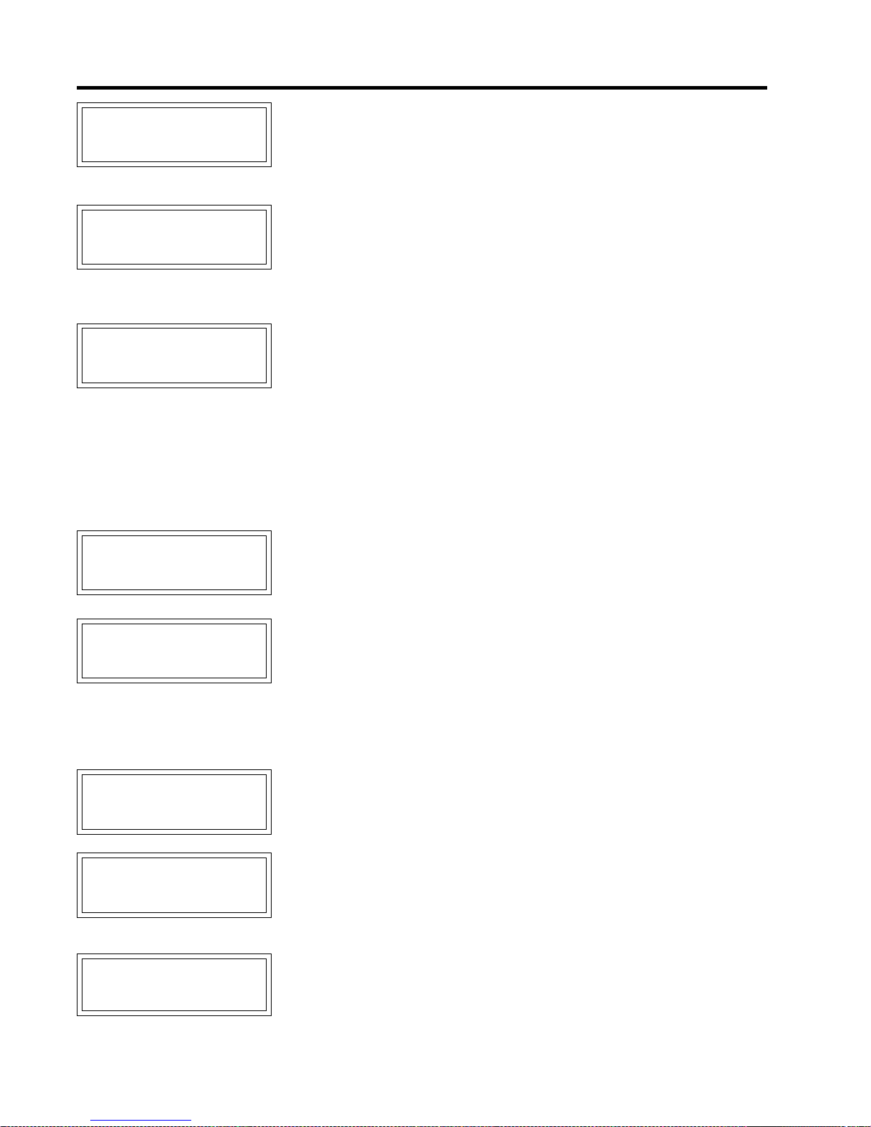
MASTER
GROUND FAUL T
LOW VOL TAGE
RTD F AILURE
TRACE
TRIP
ALARM
ALARM
Appendix C
Summary of Alarms
and their Causes
The measured ground fault current is greater than or equal to the Ground Fault Trip
setpoint.
ü Check that the setpoint is appropriate for the length and type of cable.
ü Check for wet or damaged heating cable, power connections, splices or tees.
ü Test for correct ground fault measurement.
For single and dual-point Control Modules, the measured circuit voltage is less than
or equal to the Low Voltage Alarm setpoint.
ü Check for voltage input failure by measuring the voltage at the input. On internal
switching modules, check the Heater Power In terminals; on external switching modules, check the Heater Voltage terminals.
ü Check for breaker trip.
The temperature derived from the RTD resistance is outside the range of values for
Heater Control T emperature.
ü Check for damaged RTD board mounted on the module, cable or connection if
the RTD BOARD function (msg. S3-14) is set to “On Boar d ”.
ü Check for damaged RTD Sampler, Sampler’ s address, communication over wireless RF Modem/RS485 cable if the RTD BOARD function is set to “RTD Sampler x ”.
ü Check for damaged RTD Transmitter board mounted on the module, cable or
connection if the RTD BOARD function (msg. S3-14) is set to “RTD T ransmitter”.
ü Test the R TD input.
ü RTD Short Alarm can indicate RTD Board/R TD Sampler/R TD T ransmitter failure.
ü RTD Open Alarm can indicate that a spare heater circuit is enabled.
SWITCH FAILURE
ALARM
ALARM DURING
TRACECHECK
NO RESPONSE
ALARM
SELF TEST
F AILURE ALARM
The phase current is greater than or equal to 0.1 A when the heater circuit is off.
ü Check for switch failure.
ü Test the switch input or coil voltage. When the heater circuit is off, the input or
coil voltage should be 0 Vdc. Otherwise the Module needs repair .
One of the following alarms occurred during the TraceCheck™ cycle. Refer to the
alarm details above for the individual alarm.
ü LOW CURRENT ALARM
ü HIGH CURRENT ALARM
ü HIGH CURRENT TRIP
ü GROUND FAUL T ALARM
ü GROUND FAUL T TRIP
ü SWITCH FAILURE ALARM
For the Group Interface Module, indicates that a Control Module does not respond.
ü If module does not exist on the data highway remove from the Module List.
ü Check for damaged RS-485 cable.
ü Check for Failed Control Module.
A memory or CPU failure has occurred.
ü If the alarm message occurs on the ML100 Dedicated Interface Module, the
Control Module needs repair.
ü If the alarm occurs on the MR100 Group Interface Module, the Group Interface
Module needs repair.
GF TEST
ALARM
Ground fault monitoring function did not detect the GF test current.
ü Check ground fault current transformer wiring to terminals.
ü Ground fault current transformer may be faulty.
C.2
Page 86
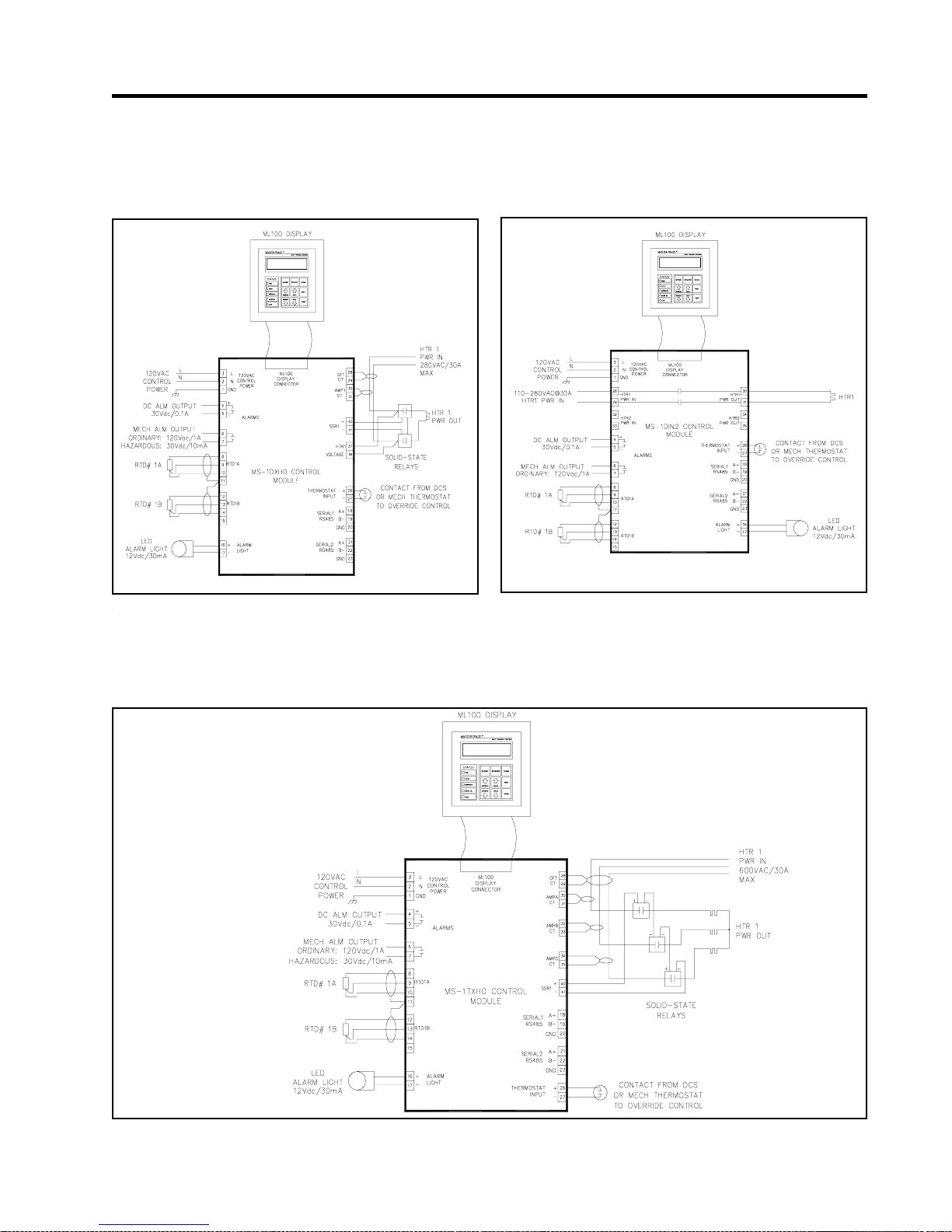
MASTER
Appendix D Typical Wiring Diagrams
MS-1DXH0 MS-1DIN2
TRACE
Appendix D
Typical Wiring Diagrams
MS-1TXH0
D.1
Page 87
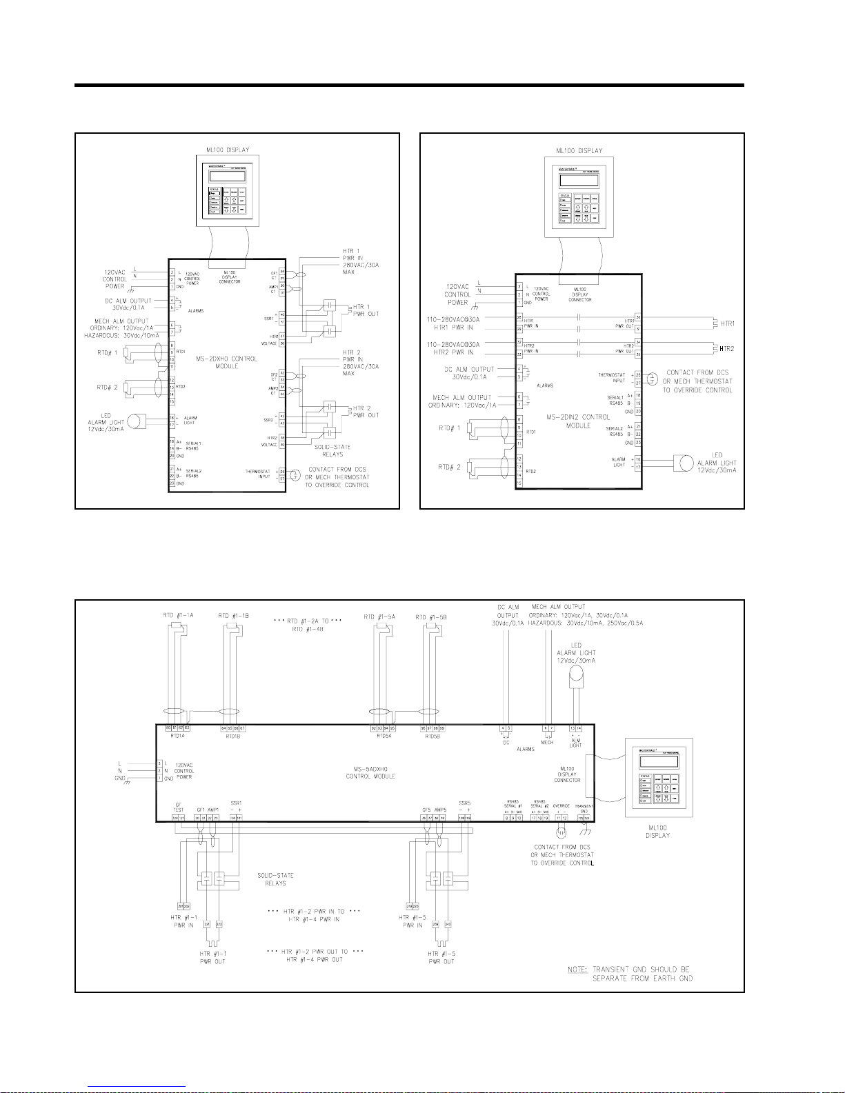
MASTER
MS-2DXH0 MS-2DIN2
TRACE Appendix D
Typical Wiring Diagrams
MS-5ADXH0
D.2
Page 88
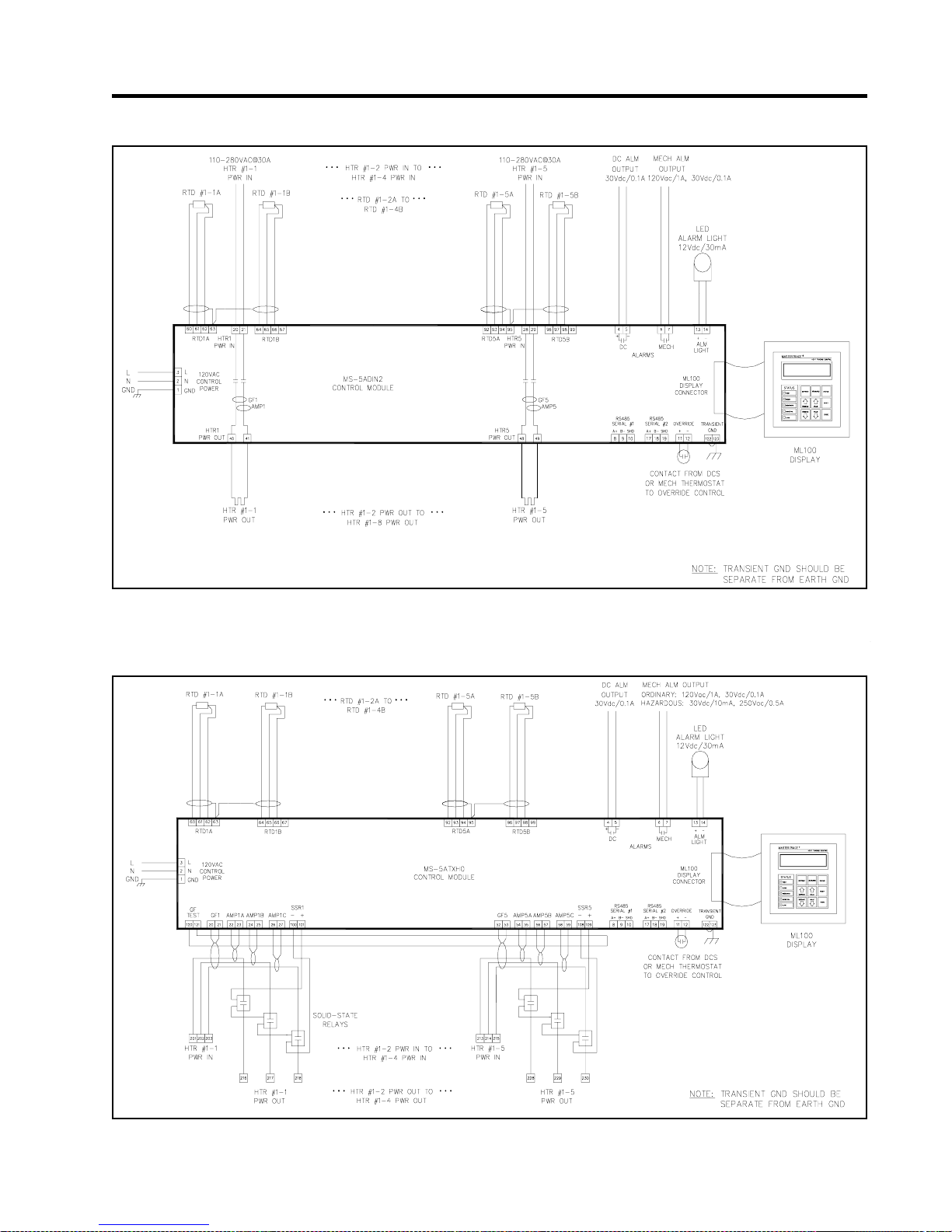
MASTER
MS-5ADIN2
TRACE
Appendix D
Typical Wiring Diagrams
MS-5ATXH0
D.3
Page 89
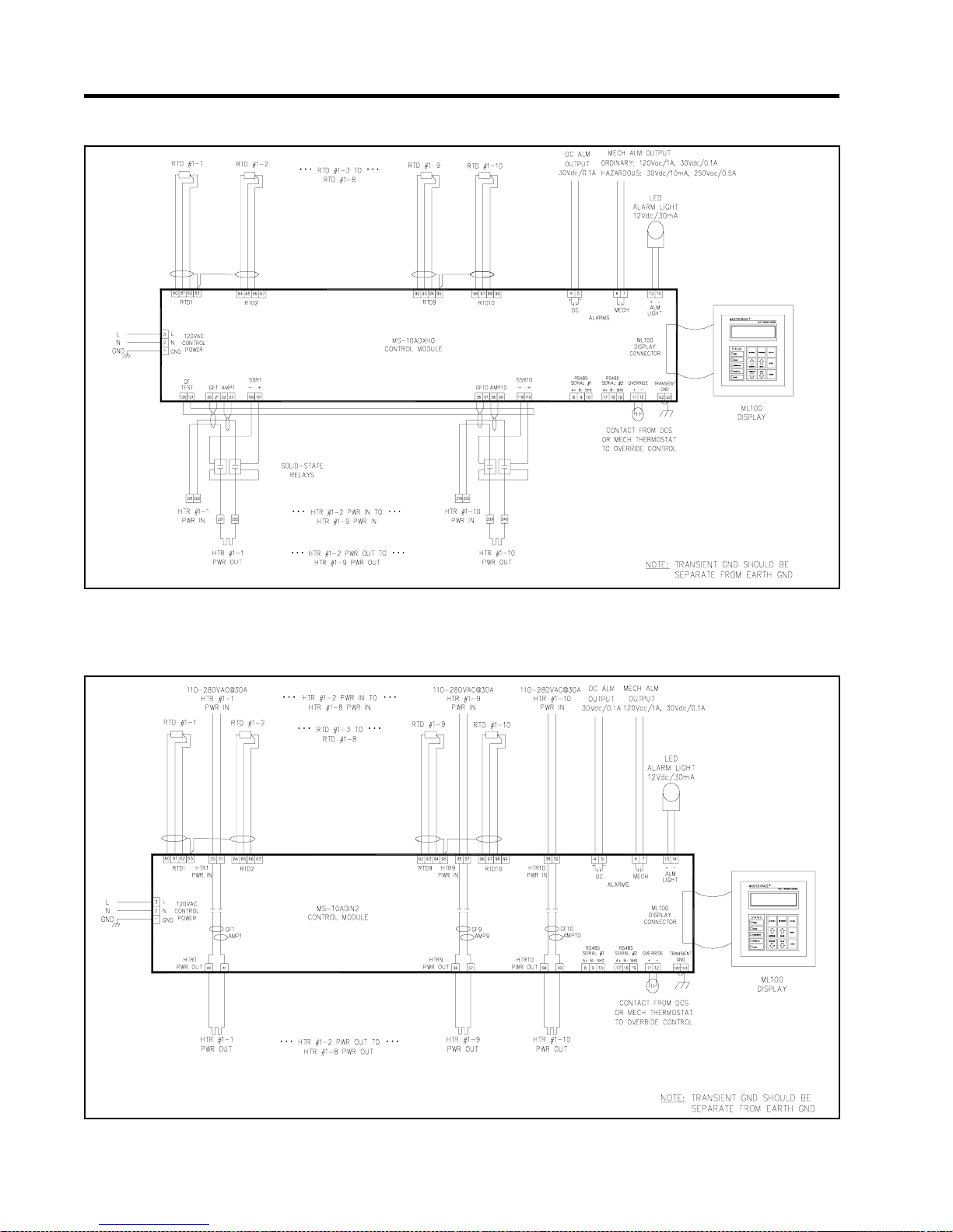
MASTER
MS-10ADXH0
TRACE Appendix D
Typical Wiring Diagrams
MS-10ADIN2
D.4
Page 90
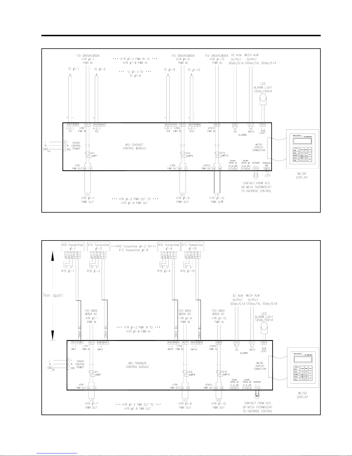
MASTER
MS-10ADIN2T
TRACE
Appendix D
Typical Wiring Diagrams
MS-10ADIN2X
D.5
Page 91
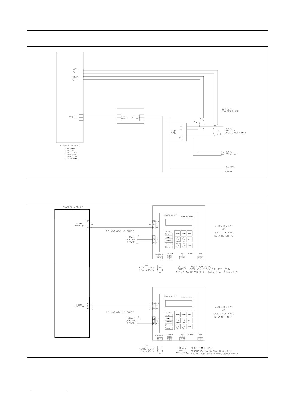
MASTER
Driving Contactors
TRACE Appendix D
Typical Wiring Diagrams
Serial Communication 1
D.6
Page 92
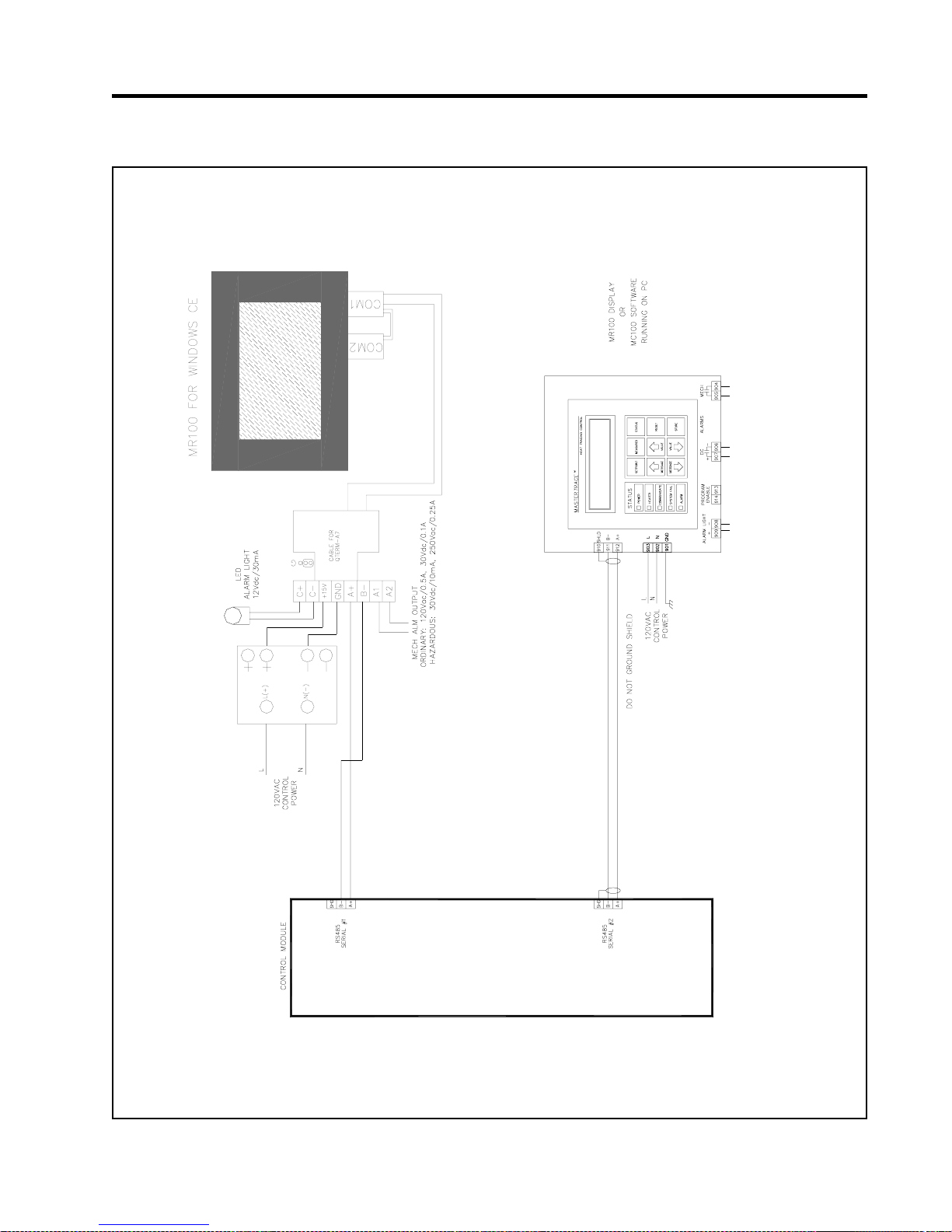
MASTER
Serial Communication 2
TRACE
Appendix D
Typical Wiring Diagrams
D.7
Page 93

MASTERTRACE
Appendix E
Freeze Protection
Introduction
Freeze protection and process control are the two most
commonly used applications of MasterTraceTM heat-tracing
controllers. In process control, the control of each heattracing point requires its own temperature measurement.
While in freeze protection, one temperature measurement
at a particular spot, called ambient temperature, is used to
control all heat-tracing control points.
Special software in MS10/MR100 has been developed
to meet customers’ various application needs. It provides
MS10/5, Nextron’s multi-point heat tracing controller, the
capability of being used in either freeze protection, or process control, or freeze protection/process control mixed application.
Additional Setpoint/Measured Messages
Two setpoint messages and one measured message are
created to give customers the flexibilty to program their
desired applications. They are:
(1) NUM OF AMB SENSE HTRS (msg. S3-11)
This message appears on both ML100 and MR100. Its
selectable choices are: 0, 1, 2, 3, 4, 5, 6, 7, 8, 9, 10, Master
1, Master 2, Master 3, Master 4, Master 5, Master 6,
Master 7, Master 8, Master 9, Master 10, Remote 1,
Remote 2, Remote 3, Remote 4, Remote 5, Remote 6,
Remote 7, Remote 8, Remote 9, Remote 10.
If NUM OF AMB SENSE HTRS = 0, the MS10 module
will be a standard MS10. All 10 heaters on the module use
their respective RTD sensors for temperature measurements.
This is a typical process control application.
If NUM OF AMB SENSE HTRS = 1, RTD1 on the
MS10 will be the local ambient R TD. Heater 1 on the MS10
will use the local ambient RTD as its temperature sensor.
Heater 2~Heater 10 will use RTD2~RTD10 as their
respective temperature sensors.
If NUM OF AMB SENSE HTRS = 2, RTD1 on the
MS10 will be the local ambient RTD. Heater 1 and Heater
2 will use the local ambient RTD’ s temperature measurement
as their temperature measurements. Heater 3~Heater 10 will
use RTD3~RTD10 as their respective temperature sensors.
This is a freeze protection/process control mixed application.
......
If NUM OF AMB SENSE HTRS = 9, RTD1 on the
MS10 will be the local ambient R TD. Heater 1~Heater 9 on
the MS10 will use the local ambient RTD’s temperature
measurement as their temperature measurements. Heater 10
will use RTD10 as its temperature sensor.
If NUM OF AMB SENSE HTRS = 10, RTD1 on the
MS10 will be the local ambient RTD. Heater 1~Heater 10
on the MS10 will use the local ambient RTD’s temperature
measurement as their temperature measurements. This is a
freeze protection application.
If NUM OF AMB SENSE HTRS = Master 1, RTD1
on the MS10 will be the global ambient RTD. Heater 1 on
the MS10 will use the ambient RTD as its temperature sensor .
Heater 2~Heater 10 will use RTD2~RTD10 as their
respective temperature sensors. Also, the MS10 will
broadcast the global ambient RTD temperature measurement
every 5 seconds through serial port 2.
If NUM OF AMB SENSE HTRS = Master 2, RTD1
on the MS10 will be the global ambient RTD. Heater 1 and
Heater 2 on the MS10 will use the global ambient RTD’s
temperature measurement as their temperature
measurements. Heater 3~Heater 10 will use RTD3~R TD10
as their respective temperature sensors. Also, the MS10 will
broadcast the global ambient RTD temperature measurement
every 5 seconds through serial port 2.
......
If NUM OF AMB SENSE HTRS = Master 9, RTD1
on the MS10 will be the global ambient RTD. Heater 1~
Heater 9 on the MS10 will use the global ambient RTD’s
temperature measurement as their temperature
measurements. Heater 10 will use RTD10 as its temperature
sensor. Also, the MS10 will broadcast the global ambient
RTD temperature measurement every 5 seconds through
serial port 2.
If NUM OF AMB SENSE HTRS = Master 10, RTD1
on the MS10 will be the global ambient RTD. Heater
1~Heater 10 will use the global ambient R TD’s temperature
measurement as their temperature measurements. Also, the
MS10 will broadcast the global ambient RTD temperature
measurement every 5 seconds through serial port 2.
If NUM OF AMB SENSE HTRS = Remote 1, Heater
1 on the MS10 will use the global ambient RTD temperature
measurement received from MS10 or MR100 as its
temperature measurement. Heater 2~Heater10 will use
R TD2~RTD10 as their respective temperature sensors.
If NUM OF AMB SENSE HTRS = Remote 2, Heater
1 and Heater 2 on the MS10 will use the global ambient
RTD temperature measurement received from MS10 or
MR100 as their temperature measurements. Heater 3~Heater
10 will use RTD3~RTD10 as their respective temperature
sensors.
......
If NUM OF AMB SENSE HTRS = Remote 9, Heater
1~Heater 9 on the MS10 will use the global ambient RTD
temperature measurement received from MS10 or MR100
as their temperature measurements. Heater 10 will use
R TD10 as its temperature sensor.
If NUM OF AMB SENSE HTRS = Remote 10, Heater
1~Heater 10 on the MS10 will use the global ambient RTD
temperature measurement received from MS10 or MR100
as their temperature measurements.
E.1
Page 94

MASTERTRACE
Appendix E
Freeze Protection
(2) AMBIENT SENSING HEATER (msg. S3-12)
This message appears on MR100 only. Its selectable
choices are: None, HT 1-1, HT 2-1, HT 3-1, ..., HT 30-1,
and MR100.
If AMBIENT SENSING HEA TER = None, the MR100
will be a standard MR100.
If AMBIENT SENSING HEATER = HT 1-1, Heater
1-1’s RTD is selected as the global ambient RTD. MR100
will read the global ambient RTD’s temperature
measurement from Heater 1-1 and broadcast this
measurement every 5 seconds.
If AMBIENT SENSING HEATER = HT 2-1, Heater
2-1’s RTD is selected as the global ambient RTD. MR100
will read the global ambient RTD’s temperature
measurement from Heater 2-1 and broadcast this
measurement every 5 seconds.
......
If AMBIENT SENSING HEATER = HT 30-1, Heater
30-1’s RTD is selected as the global ambient RTD. MR100
will read the global ambient RTD’s temperature
measurement from Heater 30-1 and broadcast this
measurement every 5 seconds.
If AMBIENT SENSING HEATER = MR100, MR100
will take the RTD connected to a 3rd party RTD transmitter as the global ambient RTD. Terminal 913 & 914 on
MR100 are the connection points between MR100 and RTD
transmitter. The actual RTD is to be locally wired to RTD
transmitter as shown in Figure E.3. Since the RTD transmitter is connected to MR100 via two 18 AWG wires, the
global ambient RTD can be located up to 7 km away from
the heat tracing panel. MR100 will read the global ambient RTD’s temperature measurement from the RTD transmitter and broadcast this measurement every 5 seconds.
(3) AMBIENT RTD TEMP (msg. S3-13)
This measured message appears on MR100 only if the
AMBIENT SENSING HEATER is not selected as None.
It displays the global ambient RTD temperature measurement from either HT 1-1, or HT2-1, ..., or HT30-1, or the
3rd party RTD transmitter connected to MR100.
Building Heat-Tracing Panel for Freeze Protection/
Process Control Mixed Application
Suppose a 20-point heat-tracing panel is to be built. The
module numbers of the two MS10 are assigned to 1 and 2 ,
respectively. The application requires that Heater 1-1, Heater
1-2, ..., Heater 1-10, Heater 2-1, ..., and Heater 2-8 are for
freeze protection application and Heater 1-1’s R TD or R TD
connected to RTD transmitter is the global ambient RTD.
Heater 2-9 and Heater 2-10 are for process control application, which means they will use their own RTD sensors.
Using the special MS10/MR100 software, this panel can
be built in the following three configurations:
(1) Configuration 1 - Panel without MR100 & AMBI-
ENT SENSING HEATER = HT 1-1
This configuration is illustrated in Figure E.1. In this
configuration, two MS10 modules are linked togather
through a RS485 cable to form a network. Three R TDs are
equiped for temperature measurement. RTD1-1 is the global ambient RTD for those 18 freeze protection heaters,
i.e., Heater 1-1, Heater 1-2, ..., Heater 1-10, Heater 2-1, ...,
and Heater 2-8. RTD2-9 and RTD2-10 are the sensors for
those 2 process control heaters, i.e, Heater 2-9 and Heater
2-10. This is a low cost panel configuration since there is
no MR100 mounted on the panel.
To meet the application requirements stated above, the
values of NUM OF AMB SENSE HTRS on the two MS10
modules have to be programmed by the hand-held ML100
like this: For module #1, set the value of NUM OF AMB
SENSE HTRS to Master 10. For module #2, set the value
of NUM OF AMB SENSE HTRS to Remote 8.
(2) Configuration 2 - Panel with MR100 & AMBIENT
SENSING HEATER = HT 1-1
This configuration is illustrated in Figure E.2. It differs
to the 1st configuration by the existence of MR100. User
can use the MR100 to program the two MS10 modules
and MR100 to meet the same application requirements as
the first configuration. Specifically, the values of NUM
OF AMB SENSE HTRS for the two MS10 modules and
the value of AMBIENT SENSING HEATER for MR100
have to be programmed like this: For module #1, set the
value of NUM OF AMB SENSE HTRS to 10. For mod-
ule #2, set the value of NUM OF AMB SENSE HTRS to
Remote 8. For MR100, set the value of AMBIENT SENSING HEATER to HT 1-1.
(3) Configuration 3 - Panel with MR100 & AMBIENT
SENSING HEATER = MR100
This configuration is illustrated in Figure E.3. It differs
to the 2nd configuration by the existence of the 3rd party
RTD transmitter. User can should use MR100 to program
the two MS10 modules and MR100 to meet the application requirements. Specifically, the values of NUM OF
AMB SENSE HTRS for the two MS10 modules and the
value of AMBIENT SENSING HEA TER for MR100 have
to be programmed like this: For module #1, set the value
of NUM OF AMB SENSE HTRS to Remote 10. For mod-
ule #2, set the value of NUM OF AMB SENSE HTRS to
Remote 8. For MR100, set the value of AMBIENT SENSING HEATER to MR100.
Important note:
For a freeze protection application, every module’s first
heater within the panel must be enabled in order for the
ambient temperature to be successfully transmitted and
received.
E.2
Page 95
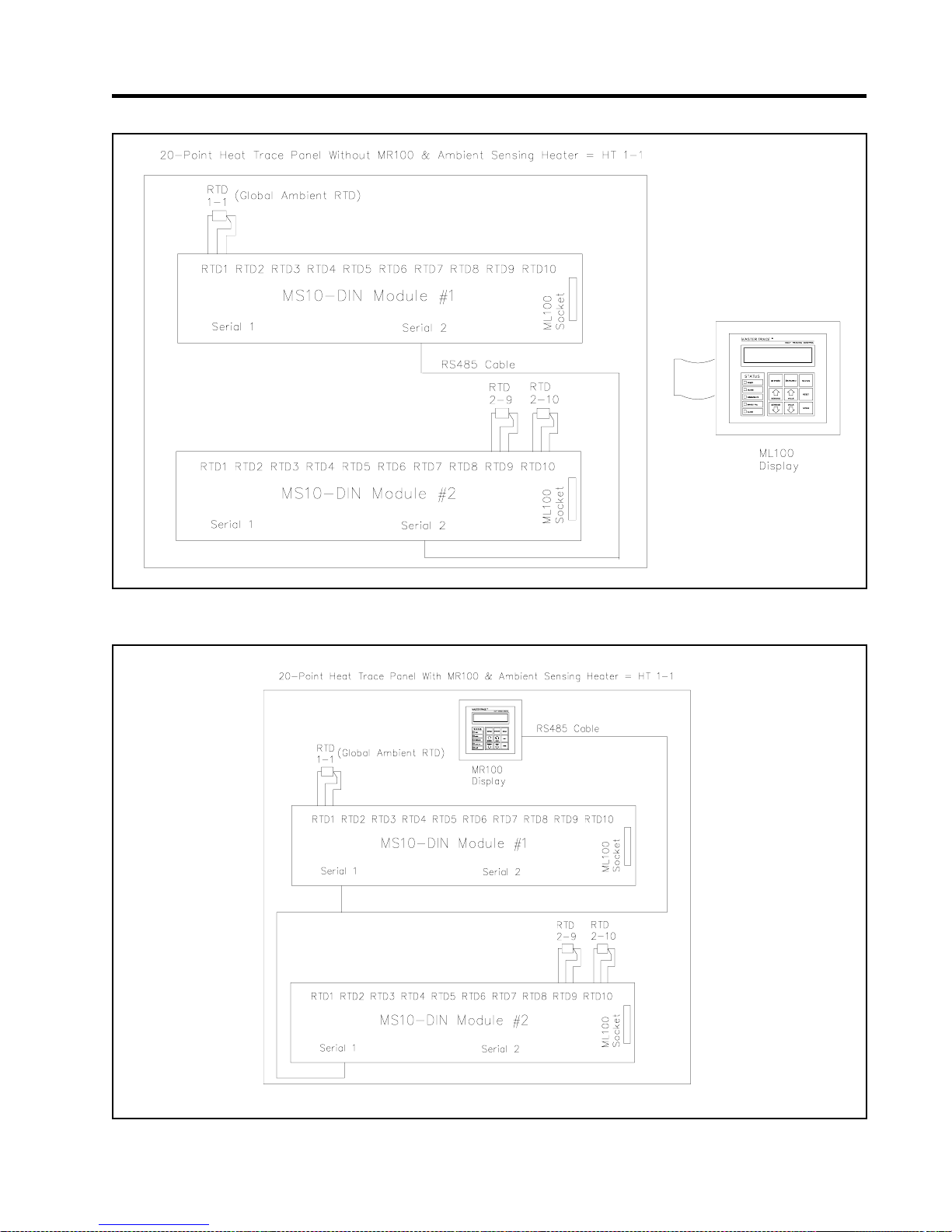
MASTERTRACE
Figure E.1 Heat-Tracing Panel Configuration 1 - Panel without MR100 & AMBIENT SENSING HEATER = HT 1-1
Appendix E
Freeze Protection
Figure E.2 Heat-Tracing Panel Configuration 2 - Panel with MR100 & AMBIENT SENSING HEATER = HT 1-1
E.3
Page 96
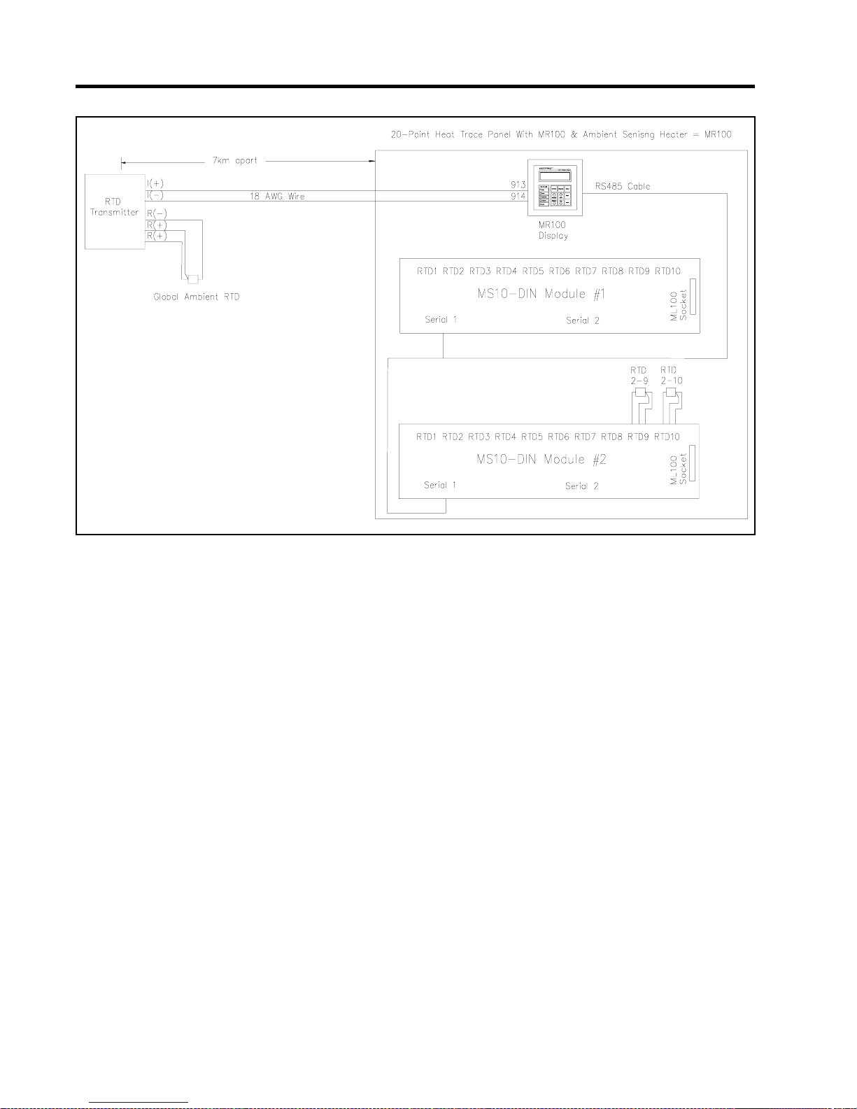
MASTERTRACE
Figure E.3 Heat-Tracing Panel Configuration 3 - Panel with MR100 & AMBIENT SENSING HEATER = MR100
Appendix E
Freeze Protection
E.4
Page 97

MASTERTRACE
Appendix F
Wireless and Wired RTD
RTD is the main temperature sensor in MasterTrace
heat-tracing controllers. Each heater in a MasterTrace
heat-tracing control module has at least one RTD input.
For RTD wiring, the conventional way is to mount one
end of the RTD, the probe, on the pipe and connect the
other end of the RTD, 3 wires, to the RTD input terminals
on the controller. If the distance between the pipe and the
controller is longer than the RTD wire, extension wires
must be added. This could be very costly. In order to reduce the wire resistance, a special RTD wire such as Beldon
cable 8770 must be used as the extension wire. Also, to
meet the industrial standard, the RTD wire must go through
aluminium conduit. For every foot of RTD extension wires,
at least $22 is added to the installation cost.
To reduce the installation cost and add more convenience and flexibility to the RTD wiring process, 4 RTD
wiring configurations, as shown in Figure F .1-F.4, are created for MasterTraceTM heat-tracing controllers. They are:
(1) On-Board RTD Wiring; (2) Transmit RTD Measurement via RS485 Cable; (3) Transmit RTD Measurement
via Wireless RF-Modem; (4) Transmit RTD Measurement
via 18 AWG wire.
The RTD BOARD function (msg. S3-14) is created to
give customers the flexibility to choose their desired RTD
wiring configuration. Its selectable choices are: RTD Sam-
pler 0, ..., RTD Sampler 15, On Board, and R TD T ransmitter.
(a) If the option “On Board” is selected, the control
module uses the RTD board directly mounted on itself to
measure heater temperatures.
(b) If the option “RTD Sampler x” is chosen, the control module uses the temperature measurements from “RTD
Sampler x” to control heaters. Here, x is the address of the
RTD Sampler.
TM
TM
The RTD Sampler is an independent temperature-measurement device and is usually located far away from the
control module. The address of an RTD Sampler can be
set to a value between 0 to 15 by positions of the dip
switches on board. An RTD Sampler can measure either
10 or 20 RTD temperatures depending on the setup. The
temperature measurement from the RTD Sampler is transmitted to the control module via either RS485 cable or RF
Modem. The communication from the RTD Sampler to
the control module is in a manner of continuous broadcast
transmission. The communication message includes not
only the temperature measurement but also the address of
the RTD Sampler. This means that any numbers of control
modules can use the same RTD Sampler as long as their
designated RTD Sampler addresses match.
(c) If the option RTD Transmitter is selected, the con-
trol module uses the temperature measurement signal received from the RTD Transmitters to control heaters.
The RTD Transmitter is another independent temperature-measurement device. The actual RTD sensor is to be
locally wired to the RTD Transmitter. The RTD transmitter is connected to the Xmitter terminals on RTD Transmitter board on the control module through two 18 AWG
wires. Refer to Figure 5.7 in Chapter 5 and Figure MS-
10ADIN2X in Appendix D for the wiring details between
the RTD Transmitter and control module. Each control
point requires a dedicated RTD Transmitter for its temperature measurement. Since the RTD Transmitter only
uses two 18 AWG wires to transmit its temperature measurement to the control module in a form of 4-20mA dc
current, the actual RTD sensor can be located up to 7km
away from the control module. This creates a great deal of
flexibility to the RTD wiring process.
F.1
Page 98
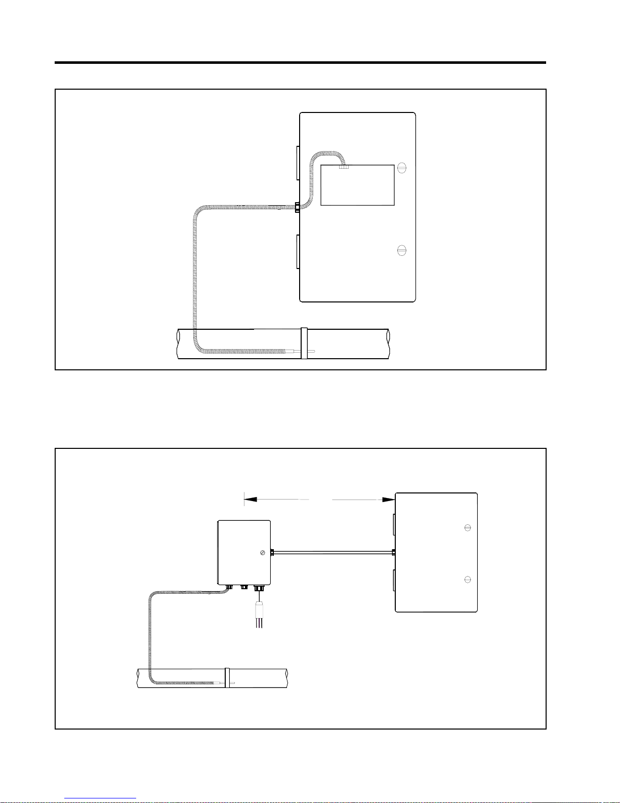
MASTERTRACE
Figure F.1 On-Board RTD Wiring
Appendix F
FWireless and Wired RTD
HEAT TRACINGPANEL
CONTROL
MODULE
Figure F.2 Transmit RTD Measurement via RS485 Cable
RTD SAMPLER
120VAC
RTD
4000 ft
RS485 CABLE
HEAT TRACINGPANEL
RTD
F.2
Page 99
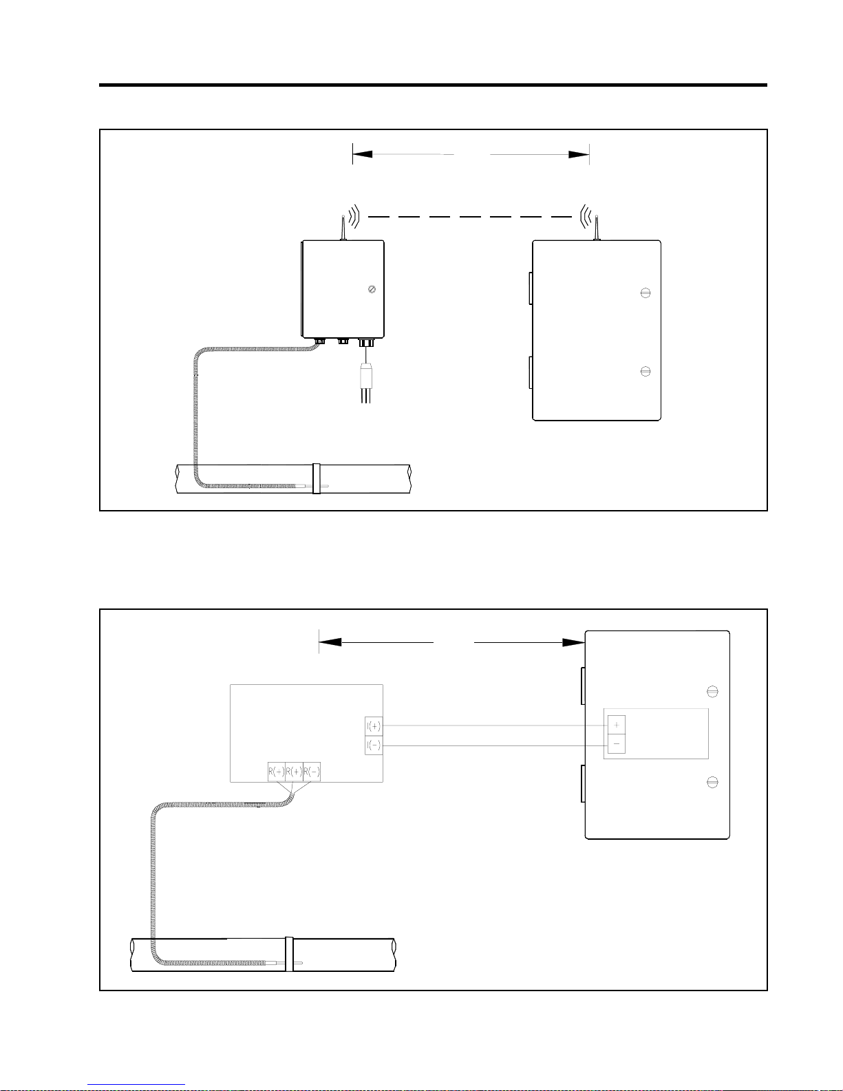
MASTERTRACE
Figure F.3 Transmit RTD Measurement via RF Modem
Appendix F
300 m
Wireless and Wired RTD
RTD SAMPLER
120VAC
RTD
Figure F.4 Transmit RTD Measurement via 18 AWG Wire
7km
HEAT TRACING PANEL
HEAT TRACING PANEL
RTD TRANSMITTER
RTD
18 AWG WIRE
F.3
CONTROL
MODULE
Page 100
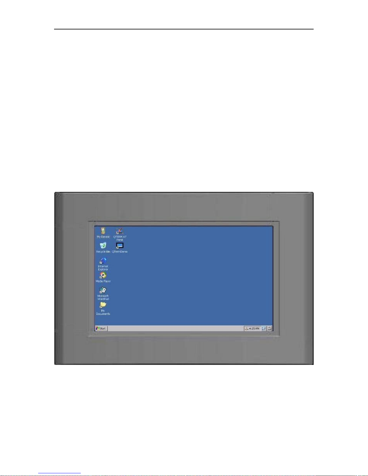
MASTERTRACE Appendix G MR100 for Windows CE
MR100 for Windows CE
1. What is MR100 for Windows CE?
MR100 for Windows CE is designed for panel-wide monitoring and programming of MasterTrace
heat tracing controllers using QTERM-A7. Th e QTERM-A7 mobile data terminal is a rugged graphic
human-machine interface terminal designed to run the Windows Embedded CE 6.0 operating system. It
communicates with Nextron’s MasterTrace control modules through RS485 serial link with facilities for
bringing data on any part of network to the QTERM-A7 screen and controlling the operation of heat tracing
circuits remotely. It provides a graphical user interface to allow the operator to easilyand quickly interpret
the data collected from the field and program the controllers as required.
2. QTERM-A7 Touch Screen
All human-machine interface activities are through the 7” touch screen. Figure G.1 is the typical
desktop screen of QTERM-A7. There are two iCons of critical importance to the operation of MR100 for
Windows CE.
(1) My Device iCon – This is the iCon to help user navigate all folders in QTERM-A7. The
executable file of MR100 for Windows CE, MR100_for_Windows_CE*.exe,isstoredat
HardDisk\MR100_for_Windows_CE* folder.
(2) On-Screen keyboard iCon – This iCon is located at the bottom right on the touch screen.
Depending on the need, the keyboard can be activated or hidden by a simple click on this iCon. Quite often
Figure G.1 – QTERM-A7 Desktop Screen
G.1
 Loading...