

Page 1
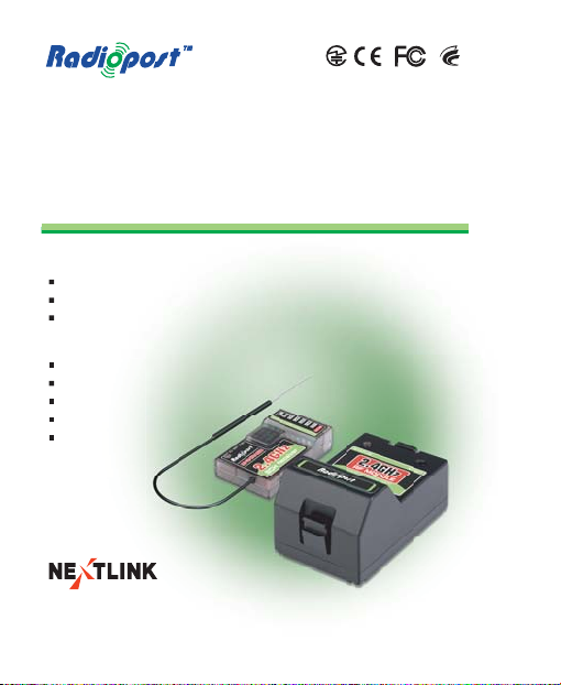
User's Manual
Handbuch
RF䊝䉳䊠䊷䊦䊶䊧䉲䊷䊋䊷ขᛒ⺑ᦠ
RF ϐʨ / Ύչд ӡٝ ԋύԅ
Tx 2.4GHz Radio Control
RP24TD9
RP24TD9J
RP24TD9M
Receiver
RP24RA4D
RP24RA5D
RP24RA6D
RP24RA8D
RP24RA9D
www.rcenjoy.com
*This user guide is subject to change without notice.
Ver.2.0
Page 2
&OHMJTI
ڋڌ
Introduction
The existing 2.4GHz Radio Control and receivers cause inconvenience
to RC users because of restricted frequency use, which comes
from FM radio technology.
Utilizing digital spectrum technology within the 2.4 GHz ISM band,
the Radiopost RF System provides secure radio link, high
transmission speed and superb resolution allowing the device
to respond quickly and accurately without interference. The
Radiopost Tx 2.4GHz Radio Control and receivers offer a significant advantage
of eliminating the possibility of interference.
Each Tx 2.4GHz Radio Control is programmed with a unique identification code
to communicate with its specified receiver. Once the receiver is
paired with the Tx 2.4GHz Radio Control (called ID Setting), the receiver will only
take data from this specific radio controller where the Tx 2.4GHz Radio Control
is equipped, ignoring signals from other sources.
The Radiopost Tx 2.4GHz Radio Control and receivers scan and select the
superior channels that are not being used to avoid collision in
channels and data loss between the Tx 2.4GHz Radio Control and the receiver.
FCC Information
This device complies with part 15 of the FCC rules.
Operation is subject to the following two conditions:
(1) this device may not cause harmful interference, and
(2) this device must accept any interference received,
including interference that may cause undesired operation.
Page 3
4BGFUZ
$BVUJPO
Precautions
Read this manual before installation or use.
Do not disassemble the Tx 2.4GHz Radio Control and the receiver
because it may cause severe damage or problems.
Install the Tx 2.4GHz Radio Control and the receiver after cutting off the
power of the radio controller and RC models such as model
aircrafts or helicopters or cars.
The receiver should be turned on after the radio controller
is switched on. When turning on the radio controller, be sure
to put the throttle to the stop position.
When switching off, make sure the engine or the motor
of the RC models should be stopped. First, switch off the
receiver then the radio controller. If this is not done in
this order, it may cause temporary malfunctions.
Prior to actual use and control of RC models, perform
operation tests between the Tx 2.4GHz Radio Control and the receiver.
If these tests fail, do not operate RC models.
When installing the receiver in RC models, use impact
protection materials to avoid damage to the receiver, which
may be caused by the vibration of RC models or the impact
from the outside.
Do not alter length of antenna arbitrarily.
The antenna should not be hidden by the RC model's main
body or cover, coated with metallic paint or carbon fiber.
Do not use Radiopost Tx 2.4GHz Radio Control and receivers together
with Tx 2.4GHz Radio Control and receivers produced by other
manufacturers.
Do not operate the Tx module with two or more receivers.
The receiver antenna shall be installed not to get affected
by the magnetic field of power cables.
* Nextlink will not be responsible for damage caused by use
which is prohibited.
&OHMJTI
ڋڍ
Page 4

Name of Each Part
www.rcenjoy.com
2.4GHz
www.rcenjoy.com
ID SET STATUS
2.4GHz
ID SETSTATUS
RP24TD9
RP24RA6D
2.4GHz
ID SET
www.rcenjo y.com
RP24RA8D
2.4GHz
ID SETF/S
5
Channel
Receiver
2.4GHz
RP24RA5D
2.4GHz
RP24RA4D
4
Channel
[For Futaba and
&OHMJTI
Hitec radio controllers]
Tx 2.4GHz Radio Control
ID Setting
Status
Button
LED
2.4GHz
RF MODULE
www.rcenjoy.com
RP24TD9
Antenna
Receiver
RP24RA4D RP24RA8D RP24RA9DRP24RA6DRP24RA5D
ID Setting
Button
Status LED
Channel
2.4GHz
4
RP24RA4D
ID SET
Antenna
ڋڎ
Antenna
[For JR radio controllers] [For Sanwa radio controllers]
RP24TD9JRP24TD9
Antenna Antenna
2.4GHz
Spread Spectrum
RF MODULE
RP24TD9J
RP24TD9M
ID Setting
Button
Antenna
Status
LED
ID Setting
Button
Status LED
ՙ՞Շ
ՙ՞Ո
ՙ՞Չ
ՙ՞Պ
ՙ՞Ջ
Յՙ՞Ռ
6CH Receiver
2.4GHz
RP24RA6D
Status LED
ID Setting Button
Failsafe Button
ՙ՞Շ
ՙ՞Ո
ՙ՞Չ
www.rcenjoy.com
Antenna
ՙ՞Պ
ՙ՞Ջ
ՙ՞Ռ
ՙ՞Ս
2.4GHz
RP24RA8D
Յՙ՞Վ
8CH Receiver
Status LED
ID Setting
Button
ՙՈՙՉՙՊ
ՙՇ
2.4GHz
ՅՙՋ
www.rcenjoy.com
5
RP24RA5D
Status
LED
ID Setting
Button
ID Setting
Button
Status LED
Failsafe Button
Antenna
Page 5
Features
High stability is guaranteed by using 2.4 GHz ISM bandwidth.
Crystal is not necessary due to automatic channel selection.
ID Setting is checked by beeping sounds.
Binding speed is superior.
&OHMJTI
Tx
Module
Receiver
The embedded Tx 2.4GHz Radio Control antenna provides convenience
for users when the stand is attached to the radio controller.
Radiopost Tx 2.4GHz Radio Control can be paired with any Radiopost
receivers.
It provides a wide range and high durability.
It is a highly sensitive receiver which is less affected by
intermodulation
It is a universal type which can be used for model
aircrafts, helicopters and cars.
It is free from "NO CONTROL" after ID Setting.
The Failsafe Function (only applied to RP24RA8D/
RP24RA9D)
minimizes damage to RC models caused by accident.
ڋڏ
Page 6
&OHMJTI
Tx
Module
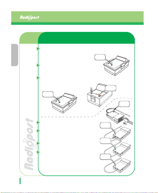
LED Status by Function
When powered on for the first
time, the green LED blinks
turning into the receiver searching
status.
When ID Setting button is
pressed, it turns into ID-Setting
mode and the red LED blinks.
When ID Setting is done, the
LED turns green and the green
color remains still.
Green color
remains still
Green LED
blinks.
Red LED
blinks
White LED
blinks
Receiver
ڋڐ
When powered on for the first
time, the white LED blinks.
When ID Setting button is
pressed, the white LED blinks
faster than previously.
When ID Setting is done, the
LED turns green and remains still.
The white LED blinks slowly if
there is no data transferred from
theTx 2.4GHz Radio Control
White LED
blinks faster
LED turns
green
White LED
blinks slowly
Power
Page 7

Installation Instructions
Choose a Tx 2.4GHz Radio Control which is suitable for the radio
controller and connect it to the controller after checking
location of the connector pins.
&OHMJTI
Mount the receiver on the proper
position after checking the servo
White LED
blinks
and the polarization of the batteries.
TheTx module will beep for three
times and the green LED will blink
when users turn on the radio controller.
Power
Connect the power to the receiver.The white LED will
begin to blink.
Press the ID Setting button of the Tx module for 1 second.
The red LED will start to blink.
Press the ID setting button of the receiver for 1 second.
The white LED will start to blink.
When the ID setting is done, the LEDs of the Tx module
and the receiver will turn green and the Tx module beeps
twice.
Check the movement of the servos by operating the lever
of the radio controller.
ڋڑ
Page 8
&OHMJTI
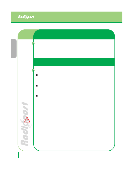
"QQMJFEUP.PEFM3'3"%
3'3"%POMZ
$BVUJPO
ڋڒ
Failsafe Function
The Failsafe Function is used to redirect the servos to
the designated location set by users in advance when
there is a connection failure or data loss for 2 seconds during
the flying session.
Failsafe Function Setup
Turning on the Failsafe Function
Turn on the Tx 2.4GHz Radio Control first and then the receiver.
Check the paring by moving the lever of the radio
controller.
By using the lever of the radio controller, set the positions
of each servo to be redirected when the Failsafe mode
gets started.
Press the Failsafe Function button for 3 seconds. The
LED will blink in red once, which means the Failsafe
Function is activated.
* When users set the Failsafe Function with the recei ver
installed in the RC models, be sure to put the engine
power channel of the radio controller in hold mode or
cut off the engine power.
*When you buy the Tx 2.4GHz Radio Control and receivers, the
Failsafe function is not activated. If wish to set the
Failsafe function, please follow instructions described
in the user guide.
Page 9
Warranty
&OHMJTI
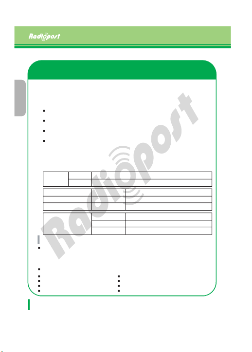
1. The warranty period for this product is 12 months from the date of retail
purchase.The warranty covers any defects in materials and workmanship
under normal use.
2. Limitations: Even within the warranty period, service charges may be
required for the followings:
The damage caused by accident, abuse, misuse, flood, earthquake or
other external causes.
The damage caused by the service performed by anyone who is not
a representative of Radiopost or a Radiopost authorized service provider.
The products or parts that have been modified to alter functionality
or capability without approval of Radiopost.
In case the seal on the module is defected or detached.
3. This warranty covers repairs of defected hardware at no charge, exchange of
it for the product which is new or equivalent to new in performance and reliability
and a refund of the purchase price.
4. If there are any product defects that arise, please contact the retail store or
the contact information below.
ڋڔ
Tx
Name of
Products
Date of purchase
Dealer or store
Tel.
Customer
Repair Service
If any difficulties are encountered while setting up or operating the modules,
please consult this instruction manual first. For further assistance you may
also refer to your hobby dealer, or contact Radiopost Service Center at the web
site or call or fax us at the numbers below;
Web site: www.rcenjoy.com
Europe, Asia Pacific
Tel.: +82-31-737-6060
Fax: +82-31-737-6263
Email: [email protected]
RP24TD9 / RP24TD9J / RP24TD9M
Receiver
RP24RA4D / RP24RA5D / RP24RA6D / RP24RA8D / RP24RA9D
Name
Address
Tel.
Warranty period: 12 months from date of retail purchase
Price:
Remarks:
North America, Latin America
Tel.: +1-949-273-8282
Fax: +1-949-273-8285
Eamil:[email protected]
Page 10

Federal Communication Commission Interference Statement
This equipment has been tested and found to comply with the limits for a Class B digital device,
pursuant to Part 15 of the FCC Rules. These limits are designed to provide reasonable
protection against harmful interference in a residential installation. This equipment generates,
uses and can radiate radio frequency energy and, if not installed and used in accordance with
the instructions, may cause harmful interference to radio communications. However, there is no
guarantee that interference will not occur in a particular installation. If this equipment does
cause harmful interference to radio or television reception, which can be determined by turning
the equipment off and on, the user is encouraged to try to correct the interference by one of the
following measures:
• Reorient or relocate the receiving antenna.
• Increase the separation between the equipment and receiver.
• Connect the equipment into an outlet on a circuit different from that to which the receiver is
con-nected.
• Consult the dealer or an experienced radio/TV technician for help.
FCC Caution: To assure continued compliance, (example - use only shielded interface cables
when connecting to computer or peripheral devices). Any changes or modifications not
expressly approved by the party responsible for compliance could void the user’s authority to
operate this equipment.This device complies with Part 15 of the FCC Rules. Operation is
subject to the following two conditions: (1) This device may not cause harmful interference, and
(2) this device must accept any interference received, including interference that may cause
undesired operation
including interference that may cause undesired operation
IMPORTANT NOTE:
FCC RF Radiation Exposure Statement:
This equipment complies with FCC RF radiation exposure limits set forth for an uncontrolled
environment. This equipment should be installed and operated with a minimum distance of 20
centimeters between the radiator and your body.This transmitter must not be co-located or
operating in conjunction with any other antenna or transmitter.
NOTE: THE MANUFACTURER IS NOT RESPONSIBLE FOR ANY RADIO OR TV
INTERFERENCE CAUSED BY UNAUTHORIZED MODIFICATIONS TO THIS EQUIPMENT.
SUCH MODIFICATIONS COULD VOIDTHE USERS AUTHORITY TO OPERATE THE
EQUIPMENT.
Page 11

IMPORTANT Safety Instruction:
1) Read these instructions.
2) Keep these instructions.
3) Heed all warnings.
4) Follow all instructions.
5) Do not use this equipment near water.
6) Do not using near any heat sources such as radiators, heat resisters, stove, or other
equipment that produce heat.
 Loading...