

Page 1
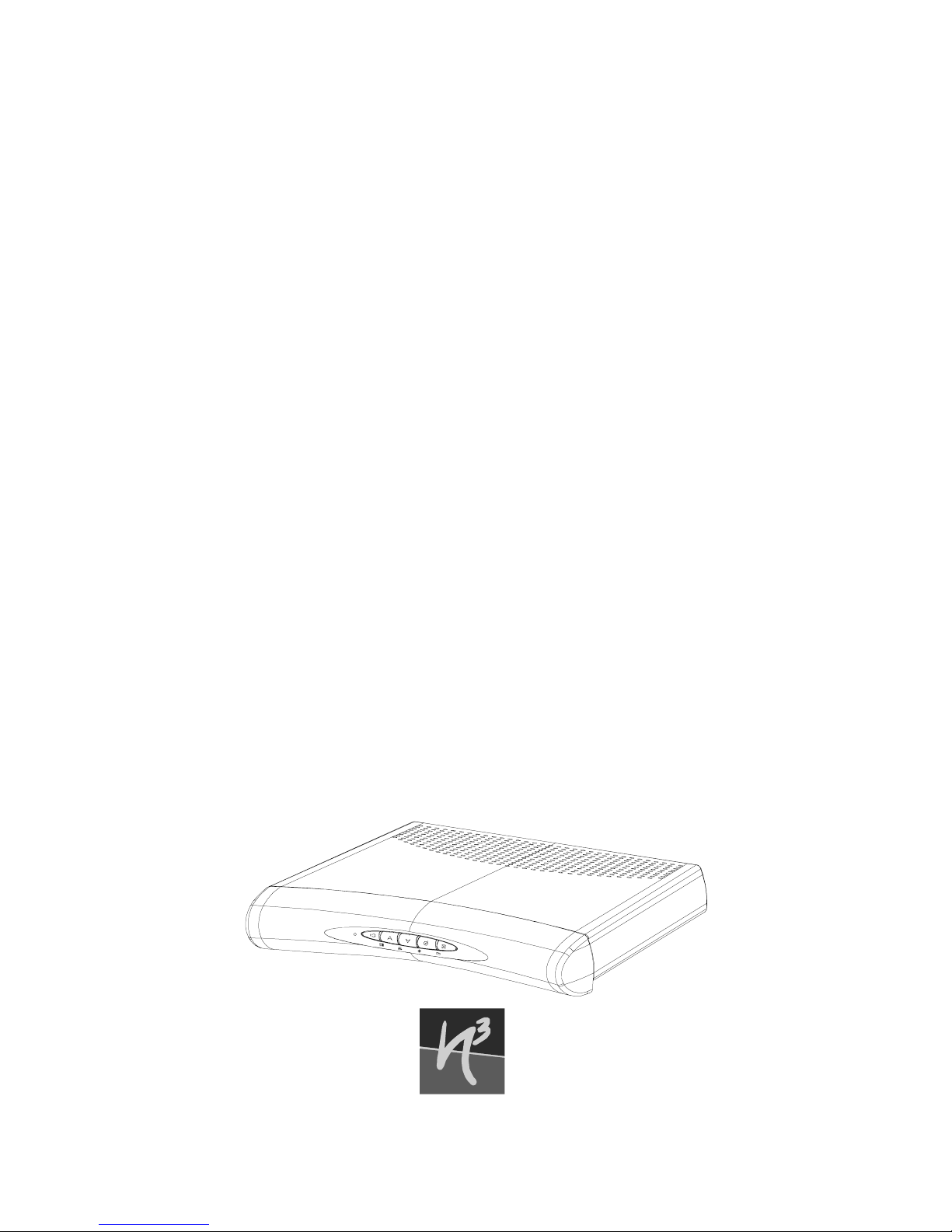
N3 Residential Gateway
User’s Guide (RG2200)
Next Level Communications
6085 State Farm Drive • Rohnert Park, CA 94928
®
Page 2

NLevel3, NLevel3 -- The Unified Access Platform, the NLC logo and N3 Residential Gateway are trademarks
of Next Level Communications in the United States and other countries.
Other trademarks are the property of their respective owners. All other products or company names are used
for identification purposes only and may be tra dem arks of their respective owners.
The following Next Level Communications product is/products are listed below with its/their proper
trademark symbol and appropriate noun, but will be referred to by product name only throughout the rest of
this document:
•N
3
Residential Gateway™ device or N3 Residential Gateway™ 2200 device
Copyright © 2002 by Next Level Communications. All rights reserved. Computer programs referred to in this
documentation contain confidential and proprietary information of Next Level Communications.
Information contained in this document is subject to change without notice. Next Level Communications
assumes no responsibility for any errors that may appear in this document, nor liability for any damages arising
out of the us e of this document. No part of t hi s document ma y b e r ep r oduced in an y fo r m by electron ic or
mechanical means (including photoco pying, recording, or information storage and retrieval) without
permission in writing from Next Level Communications.
Document Number 600-00244 B01. Date November 2002
This guide is written to Release 3.6.12 capabilities
Page 3

3
TABLE OF CONTENTS
IMPORTANT SAFEGUARDS.................. ...... ....... ...... ....... ...... ....... ...... ................ 5
Safety ...........................................................................................................8
Repairs .........................................................................................................8
INTRODUCTION ..................... ...... ....... ...... ....... ...... ....... ...... ............................. 9
About This Manual .....................................................................................10
What Your Network Service Provider Does ................................................11
About VHF Channels .................................................................................12
Write Your Remote Control and Other IDs Here ........................................13
GETTING STARTED ....................................................................................... 15
Using Your RG2200 ...................................................................................16
Using Your Remote Control ........................................................................19
Caller ID/Message Waiting .........................................................................24
Using Pay-Per-View ...................................................................................27
Access Parental Control .............................................................................27
Recording Your Favorite Programs ............................................................29
Cancelling Your Recording .........................................................................30
Programming Your VCR Code ...................................................................31
Replacing Remote Control Batteries ..........................................................32
ADVANCED USE............................................................................................ 33
Changing or Programming Settings ...........................................................33
Determining the Gateway ID ......................................................................34
Setting the Gateway ID ..............................................................................38
Page 4

4
Determining the Remote Control ID ...........................................................39
Setting the Remote Control ID ...................................................................40
Programming the TV Code .........................................................................42
Programming the Remote Using Code Search Method .............................43
Verifying the TV Codes ...............................................................................43
Verifying and Setting Other Features .........................................................44
Accessing the TV Setup Menu ...................................................................44
Verifying the TV (RF) Setting ......................................................................46
Secondary Audio: Specifying A Preferred Language .................................48
Display Language .......................................................................................49
Closed Captioning ......................................................................................50
Teletext .......................................................................................................51
EADS (Emergency Alert Device Support) ..................................................51
CONNECTING YOUR PC TO THE INTERNET ..................................................... 55
Ethernet Connections .................................................................................55
CONFIGURATION EXAMPLES........................................................................... 59
TV/VCR/Audio Connections .......................................................................61
TROUBLESHOOTING....................................................................................... 71
C
ONTACTING YOUR NETWORK SERVICE PROVIDER FOR HELP ........................ 76
TV
AND VCR CODES .................................................................................... 77
TV Codes .................................................. ..... ........................................ ....77
VCR Codes ................................................................................................80
SPECIFICATIONS............................................................................................ 83
Certifications ...............................................................................................84
FCC Statement of Compliance ...................................................................85
INDEX ........................................................................................................... 87
Page 5

5
IMPORTANT SAFEGUARDS
READ INSTRUCTIONS – All the safety and operating instructions should be read before
the product is operated.
R
ETAIN INSTRUCTIONS – The safety and operating instructions should be retained for
future reference.
H
EED WARNINGS – All warnings on the product and in the operating instructions should
be adhered to.
C
LEANING – Do not use liquid or aerosol cleaners to dust this product. Use a cloth
lightly dampened with water for cleaning.
A
TTACHMENTS – Do not use attachments that are not recommended as they may
cause a hazard.
W
ATER AND MOISTURE – Do not use this product near water; for example, near a bath
tub, wash bowl, kitchen sink, or laundry tub, in a wet basement, or near a swimming
pool.
A
CCESSORIES – Do not place this product on an unstable cart, stand, tripod, or table.
The product may fall causing damage to the product.
Page 6

6
VENTILATION – Slots and openings in the product housing are provided for ventilation,
to ensure reliable operation of the product, and to protect it from overheating the following should be observed:
• Openings should never be blocked by placing the product on a bed, sofa, rug, or
similar surfa ce .
• Do not stack other equipment on top of the RG2200.
• Maintain at least 2 inches of free space above the RG2200.
• Equipment should never be placed near or over a radiator or heat register, or in a
built-in installation such as a bookcase or rack unless proper ventilation is provided.
P
OWER SOURCES – This product should be operated only from the type of power
source indicated on the marking label. If you are not sure of the type of power supplied
to your home, consult your local power company. For equipment intended to operate
from battery power or other sources, refer to the operating instructions.
G
ROUND OR POLARIZATION – This product may be equipped with a polarized alternat-
ing current line plug (a plug having one blade larger than the other). This plug will fit
into the power outlet in only one way. This is a safety feature. If you are unable to
insert the plug fully into the outlet, try reversing the plug. If the plug should still fail to fit
into the outlet, contact an electrician to replace your obsolete outlet.
P
OWER CORD PROTECTION – Power cords should be routed so they are not likely to be
walked on or pinched by items placed upon or against them, paying particular atten-
Page 7

7
tion to cords at plugs, convenience receptacles, and the point where the plugs exit
from the product.
P
OWER SOCKET OUTLET – Use a power socket outlet located near the equipment that
is easily accessible.
L
IGHTNING – For added protection for this product during a lightning storm, or when it
is left unattended, unplug it from the wall outlet. This will prevent damage to the video
product due to lightning and power line surges.
O
VERLOADING – Do not overload wall outlets and extension cords, as this can result in
a risk of fire or electrical shock.
O
BJECT AND LIQUID ENTRY – Never push objects of any kind into this product through
openings as they may touch dangerous voltage points or short-out parts that could
result in a fire or electrical shock. Never spill liquid of any kind on the product.
S
ERVICING – Do not attempt to service this equipment yourself as opening or removing
covers may expose you to dangerous voltage or other hazards. Refer all servicing to
qualified service personnel.
D
AMAGE REQUIRING SERVICE – Unplug this product from the wall outlet and refer ser-
vicing to qualified service personnel under the following conditions:
• When the power supply cord or plug is damaged
• If liquid has been spilled or objects have fallen into the equipment
Page 8

8
• If the product does not operate normally by following the operating instructions
• If the product has been dropped or the housing has been damaged
• When the product exhibits a distinct change in performance
S
AFETY CHECK – Upon completion of any service or repairs to the product, ask the ser-
vice technician to perform safety checks to determine that the product is operating
properly.
SAFETY
This section reviews important safety concepts for working with the optical and electrical equipment covered in this guide.
SAFETY ADVISORIES AND LABELS
Important warning notices, if any , are located on the back of the RG2200 about safety
to people and equipment. Failure to observe these rules and similar danger, caution,
or warning notices can result in serious personal injury, service interruption, and
equipment damage.
REPAIRS
If you find the unit in need of repair, contact your network service provider for repair or
replacement. WARNING! Disconnect unit before servicing.
Page 9
9
INTRODUCTION
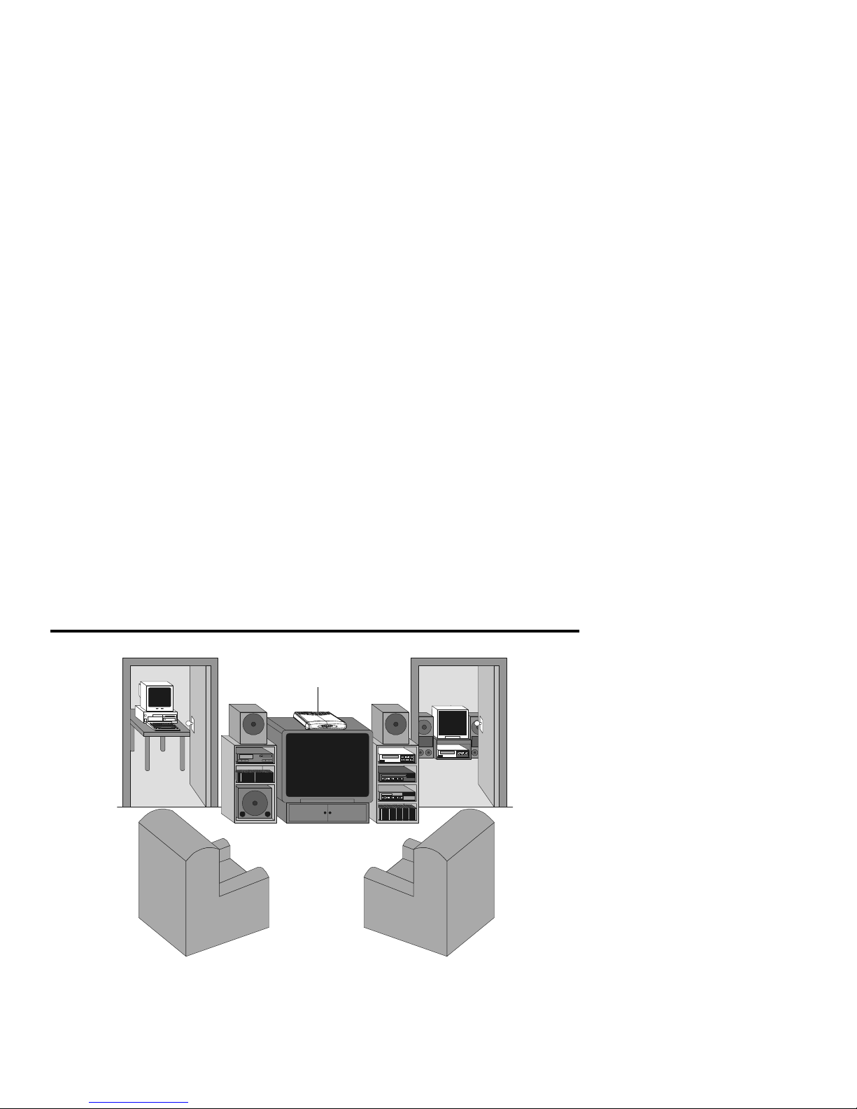
Beneath the compact and stylish exterior of the RG2200 is a powerful media delivery
system. The RG2200 is different from other video boxes that you may have encountered. Some competitor boxes are designed to deliver one video/audio channel to a
RG2200
Page 10

10
single TV and/or VCR device. In contrast, the compact RG2200 delivers the functionality of two or three high-quality digital video boxes in a single package. Depending on
the model you have, the RG2200 can deliver separate xDSL video services to up to
three TVs at the same time. It also provides a high-speed xDSL modem for Internet
access and telephony capabilities, such as Caller ID and Message Waiting display.
ABOUT THIS MANUAL
The information in this manual is applicable to ADSL or VDSL versions of the Resi-
dential Gateway RG2200. The term xDSL is a generic term, used in this manual, to
refer to both ADSL and VDSL technologies.
G
ETTING STARTED on page 15 contains the information you use most frequently and
helps you understand how the RG2200 works after your NSP (network service provider) has connected and programmed its functions. It also describes how to use the
RG2200 remote control to access and control the basic features of the RG2200.
A
DVANCED USE on page 33 provides more technical information about the RG2200
and gives instructions about how to set up and program your system.
C
ONFIGURATION EXAMPLES on page 59 illustrates possible component wiring configu-
rations of the RG in your system to aid you if you want to move your equipment or
connect additional equipment such as an entertainment center or a new VCR.
Page 11

11
CONNECTING YOUR PC TO THE INTERNET on page 55 briefly explains co nnec ting your
PC to the Internet using an optional Ethernet card or HPNA card. Illustrations show
configurations for setting up a LAN (local area network) in your home.
T
ROUBLESHOOTING on page 71 provides help for problem resolution.
WHAT YOUR NETWORK SERVICE PROVIDER DOES
The NSP (network service provider) is the company that installs your telephone and
data services, as well as possibly providing Internet service. Some telephone companies, however, use an ISP (Internet service provider) company to offer Internet service
to their customers.
During the initial installation your NSP does the following:
• Installs the RG2200 and connects it to your home entertainment system.
• Sets all features and services to which you have subscribed including:
• Wiring additional rooms with coaxial cable for secondary TVs.
• Connecting secondary TVs (TV2 and TV3) to the network and to any splitters
and RAP(s) (remote antenna package) that are required.
• Connects and configures your PC(s) to access the Internet.
• Ensures that all the remote controls in your home used with your RG2200 are the
correct model.
• Installs the batteries in your remote control.
• Programs your remote cont rol(s) to operate a specific TV.
Page 12
12
• Provides labels for your remote controls to let you label one remote for each TV.
• Writes the remote control IDs in the space provided (see form below).
ABOUT VHF CHANNELS
Your NSP sets your TV to operate on a specific VHF (very high frequency) channel.
This setting allows you to receive video and audio broadcast services.
Programming the TV to a VHF channel is similar to setting a TV to a specific channel,
such as channel 3, in order to view movies played on your VCR. After the RF channel
has been set, it is recommended that you do not change it, as you will no longer be
able to receive programming unless you retune your TV to a new VHF channel.
Once your TV is tuned to the specified VHF channel, the RG2100 and your remote
allow you to surf through the channel line-up and tune to any program from any TV
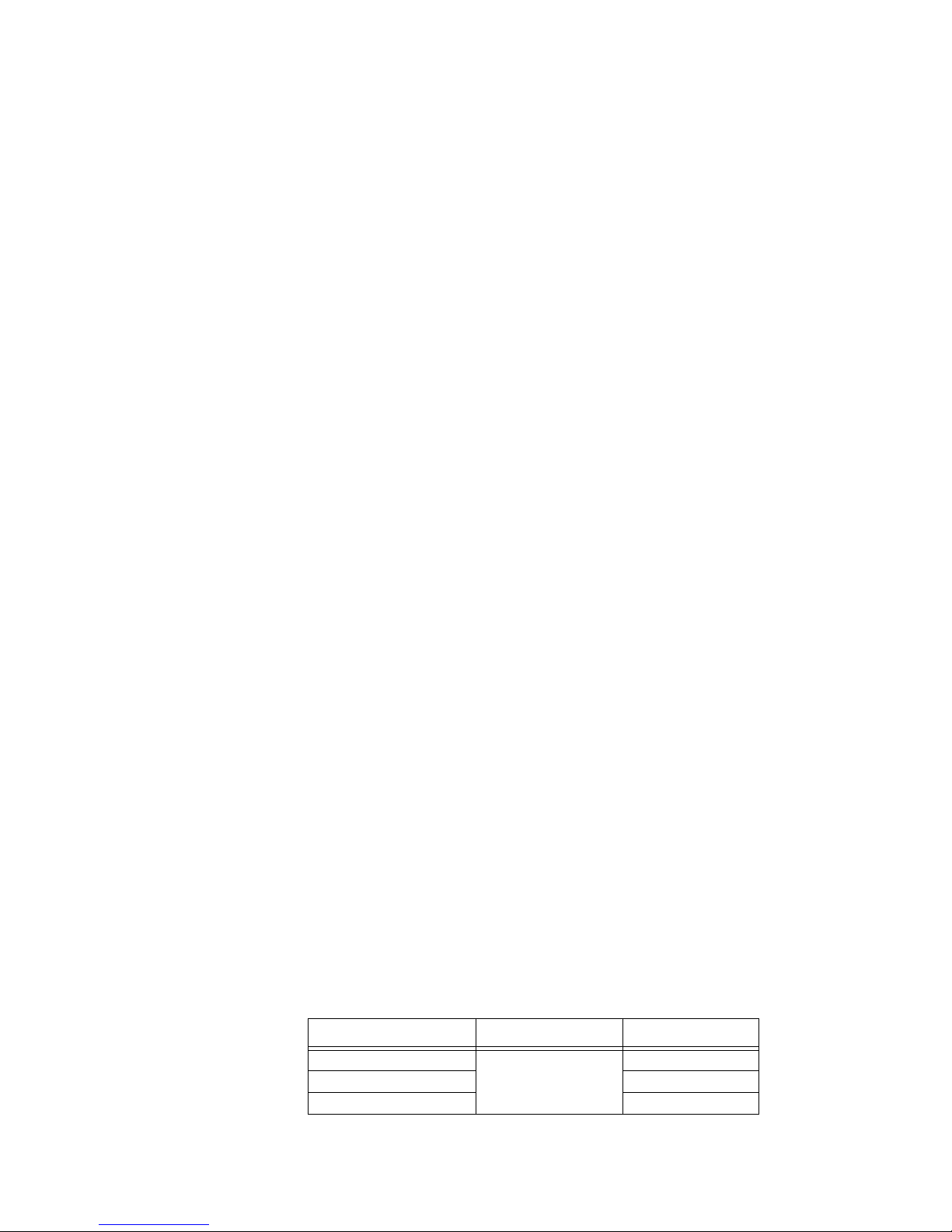
viewing location. The table below demonstrates how the TV outputs and the VHF
channels work together to deliver video and audio programming.
TV OUTPUT Ports
VHF Channel
1
TV1 NETWORK IN/T V OUT
and/or
TV OUT
3, 4, 5, or 6
TV2 7, 8, 9 or 10
TV3 (VDSL only) 11, 12 or 13
1. The VHF channels are a list only. Actual VHF channels used will vary
according to location and will be determined by your NSP.
Page 13

13
WRITE YOUR REMOTE CONTROL AND OTHER IDS HERE
You may wish to label each of your remote controls so you can easily identify which
TV they have each been programmed to control. Ask your service provider for labels if
they have not already been provided for you.
Write your remote control ID here:
TV1 _____ TV2 _____ TV3 _____
Write your TV code here:
TV1 _____ TV2 _____ TV3 _____
Write your Gateway ID here:
____ ____ ____
Page 14

14
Page 15

15
GETTING STARTED
This section contains basic information needed to get you started using your new
NLevel
3
Residential GatewayTM 2200 right away. This information is covered in the
following subsections:
• “Using Your RG2200” on page 16
• “Using Your Remote Control” on page 19
• “Changing Channels” on page 21
• “Controlling TV Volume” on page 21
• “Setting Up Channel Order and Your Favorite Channel List” on page 22
• “Caller ID/Message Waiting” on page 24
• “Using Pay-Per-View” on page 27
• “Access Parental Control” on page 27
• ”Recording Your Favorite Programs” on page 29
• ”Cancelling Your Recording” on page 30
• ”Programming Your VCR Code” on page 31
• “Replacing Remote Control Batteries” on page 32
Page 16
16
USING YOUR RG2200
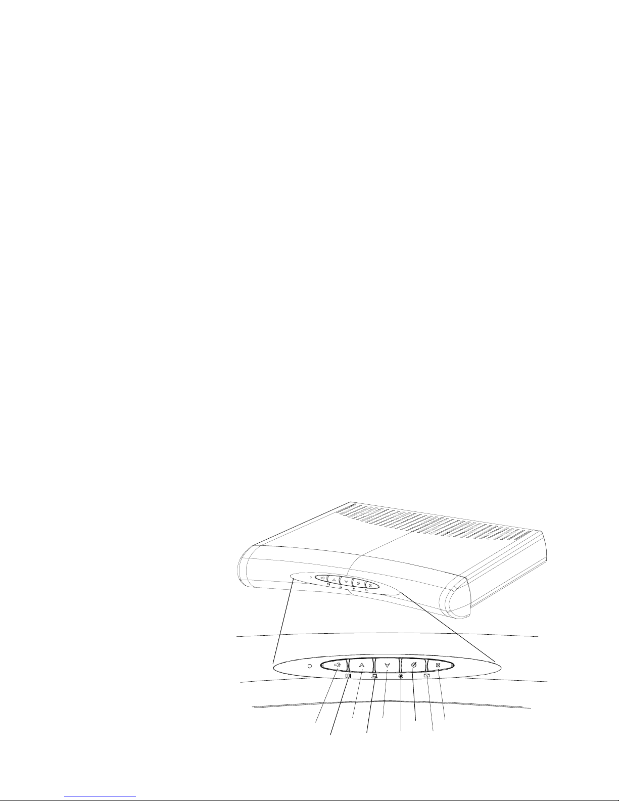
The illustration below shows the controls you need to be familiar with when using the
RG2200. Go to the tables on the next page for description of their function.
14325
8769
Page 17
17
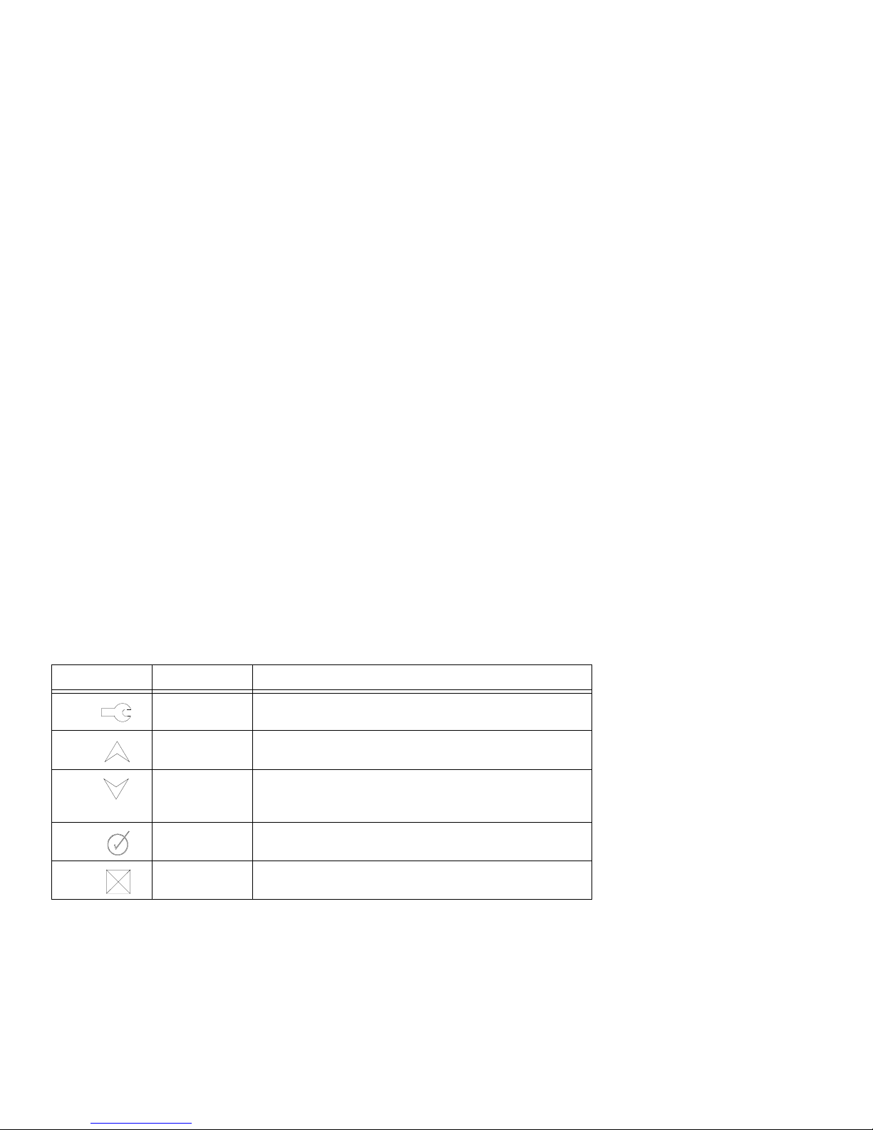
The following table describes the buttons on the front of the RG2100. These buttons
operate at the primary viewing location, which is TV1.
Symbol Name If you press the button, this happens.
1. SETUP Displays the Gateway Menu.
2. UP arrow Increases the channel number. When you are using the
on-screen program guide or menu, moves the cursor up.
3. DOWN
arrow
Decreases the channel number. When you are using the
on-screen program guide or menu, moves the cursor
down.
4. SELECT While in the program guide or menu, selects the
highlighted choice.
5. EXIT Exits the current menu . Reb oots (restarts) the RG 22 00 i f
pressed and held for 5 seconds or more.
Page 18
18
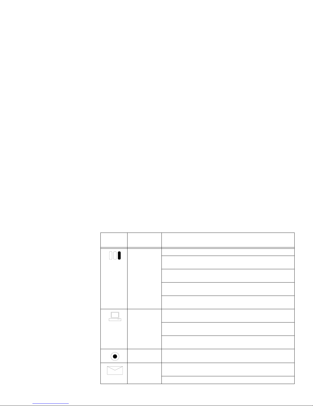
LED symbols and descriptions.
LED
Symbol
RG2200
LEDs
What the lights mean
6. STATUS If the LED is off, there is no power to the RG2200.
A blinking red LED indicates the RG2200 is attempting to
communicate with the network .
A blinking amber LED indicate s the RG2200 is commu nicating
with the network.
A solid green LED indicates the RG2200 is communicating
with the network and is ready to use.
A blinking green LED indicates the RG2200 is not ready to
use.
7. ONLINE No light, or off, indicates ther e is no active PC detected on the
data port.
An amber light indicates the RG2200 has detected an active
PC on the data port, but the RG22 is not yet ready for use.
A solid green LED indicates the RG2200 has detected an
active Ethernet PC or hub on the Ethe rnet and is rea dy for us e.
8. RECORD A red LED indicates a program is being recorded.
9. MESSAGE A green LED indicates one or more voice mail messages are
present.
When the LED is off there are no voice mail messages.
Page 19

19
USING YOUR REMOTE CONTROL
The remote control allows you to control TV viewing from anywhere in your home.
Your NSP (or yourself) can program it to operate your TV as well as your RG2200.
The remote control operates by sending either IR (infrared) or UHF (ultra-high frequency) signals to the RG2200. Y our Network Service Provider programs your remote
to operate in the most appropriate mode for your home.
If your remote control is programmed for IR mode, it requires a direct line-of-sight in
order to function. In other words, you need to point an IR remote directly to the television or the RG2200. You can only use an IR remote to operate a TV that is located in
the same room as the RG2200. If your primary TV (TV1) located in a different room
than the RG2200, the remote must be programmed to use
UHF mode.
Remote controls that control secondary TVs (TV2, TV3), are also programmed to
operate in UHF mode.
Page 20
20
R
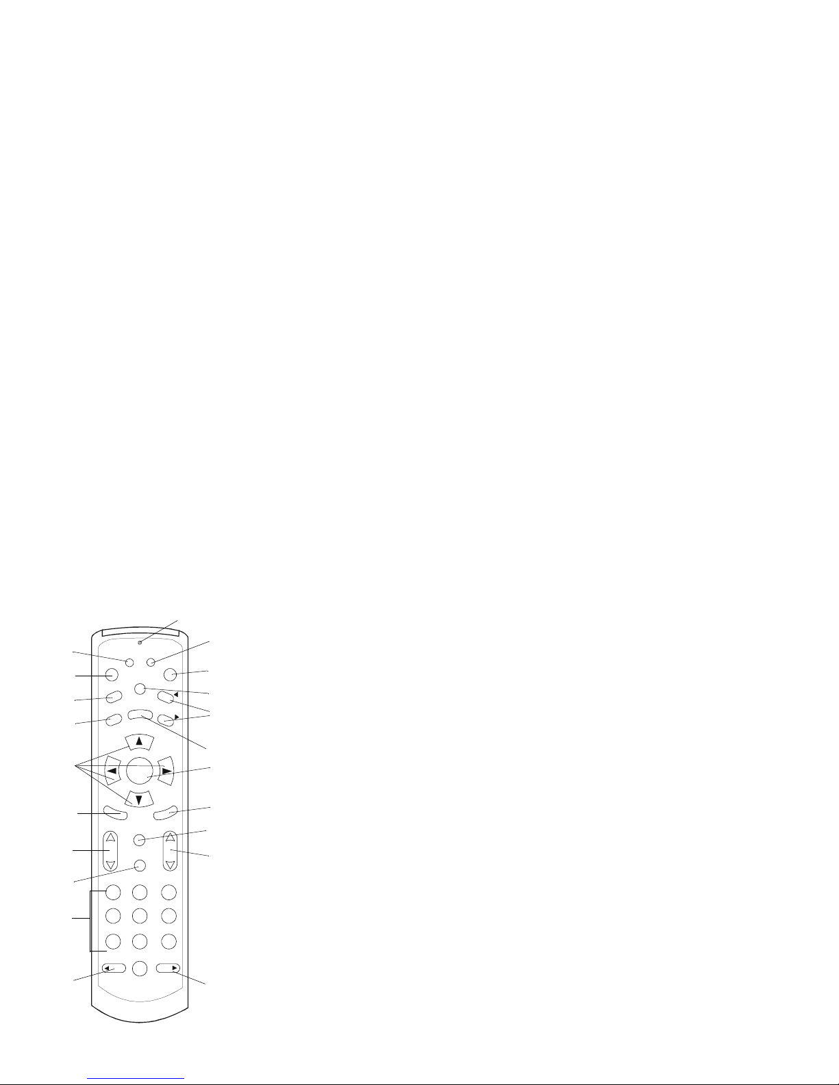
EMOTE CONTROL BUTTONS
A. When pressed, starts Remote ID programming sequence.
B. Displays Pay Per View menu.
C. Opens Caller ID screen.
D. Exits current menu and returns you to previous screen.
E. Arrows move cursor in Program Guide & menu screen.
F. Scans through favorite channels.
G. Adjusts TV volume.
H. Mutes TV sound. When pressed and held, initiates TV Remote setup.
I. Selects channels (0-9).
J. Move program guide back 24 hours.
K. When pressed, starts Gateway ID programming sequence.
L. Powers TV on/off and tunes to default channel.
M. Displays Main Menu.
N. Pages up and down in interactive program guide and menu screens.
O. Displays interactive program guide.
P. Selects highlighted option.
Q. Recalls last channel.
R. Displays current channel and program information.
S. Changes program channel.
T. Moves program guide forward 24 hours.
GUIDE
SELECT
V
O
L
C
H
A
N
M
E
N
U
B
A
12 3
45 6
78 9
0
DAY
DAY
F
A
V
L
A
S
T
C
H
MUTE
INFO
E
X
I
T
C
A
LL
I
D
P
P
V
P
O
W
E
R
P
A
G
E
P
A
G
E
K
N
R
Q
S
T
M
L
A
B
C
E
D
F
G
I
J
H
O
P
LED
Page 21

21
A
CTIVATING THE RG2200
The RG2200 doesn’t have an on/off button. However, if your NSP has activated the
“One Touch Power” option, the RG2200 can be put into a power saving mode when
you use the POWER button on the remote to turn the TV off. It is reactivated when the
TV is turned on using the same button.
CHANGING CHANNELS
To change the channel using the remote control buttons do one of the following:
• Press the up or down arrow on the CHAN button.
• Enter the channel number on the number key pad and press SELECT.
• Enter the channel number on the number key pad and wait 5 seconds, the
RG2200 will go to the channel entered.
To change the channel using the RG2200 buttons:
• Press the up or down arrows on the front panel.
CONTROLLING TV VOLUME
To raise or lower the volume on your TV using your remote control:
1. Press the up or down arrow on the VOL button.
Page 22

22
T
O MUTE OR UNMUTE THE TV VOLUME USING YOUR REMOTE CONTROL:
1. Press the MUTE button on the remote to mute your TV.
2. Press it again to unmute the TV.
SETTING UP CHANNEL ORDER AND YOUR FAVORITE CHANNEL LIST
You can use the remote control to select what channels will appear in your guide, set
up your TV channel order or create a list of your favorite channels. Once your favorite
channel list is set up, it can be accessed by pressing the FAV button on your remote
control.
TO SELECT CHANNEL LIST:
1. Press the MENU button on your remote control
The Main Menu screen of your interactive program guide is displayed.
2. Use the down arrow to highlight “Setup The Channels.”
3. Press SELECT.
An options screen is display ed .
4. Use the down arrow to highlight “Select Channels.”
5. Press SELECT.
Page 23

23
6. Follow the instructions on the screen using your remote control buttons.
7. When you have completed your selection, press EXIT to return to the previous
screen.
TO ARRANGE THE CHANNEL ORDER:
1. Press MENU.
The Main Menu screen of your interactive program guide is displayed.
2. Use the up or down arrow to highlight “Setup The Channels.”
3. Press SELECT.
An options screen is displayed.
4. Use the down arrow to highlight “Change Channel Order.”
5. Press SELECT.
6. Follow the instructions in the interactive program guide.
7. When you have completed your selection, press EXIT to return to the previous
screen.
TO CREATE A FAVORITE CHANNEL LIST:
1. Press MENU.
Page 24

24
The Main Menu screen of your interactive program guide is displayed.
2. Use the down arrow to highlight “Setup The Channels.”
3. Press SELECT.
An options screen is display ed .
4. Use the down arrow to highlight “Favorite Channels.”
User Tip:
Selecting channels
to be included in the Favorite
Channel List can also be performed in Pay-Per-View and
when in the program guide
menu.
5. Press SELECT.
6. Follow the instructions in the interactive program guide to select your favorite
channels.
7. When you have completed your selection, press EXIT to return to the previous
screen.
Now, whenever you access the program guide or press the FAV button on your
remote control, the channels will be listed in the order you selected.
CALLER ID/MESSAGE WAITING
If you have subscribed to Caller ID, V oice Mail or Call Waiting services with your NSP,
these capabilities are enabled as soon as the RG2200 is connected to the network.
Page 25
25
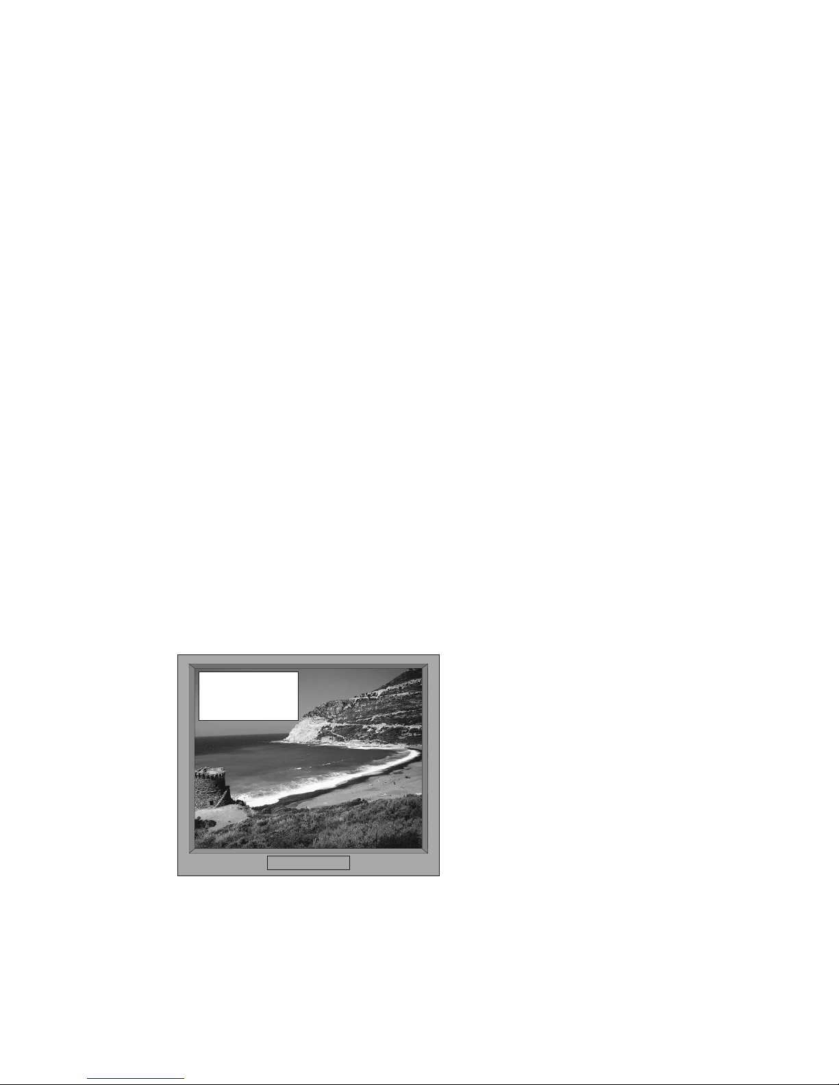
When an incoming call arrives, the message LED on the front of the RG2200 is illuminated and caller ID information appears in the upper left-hand corner of each of the
TVs that is caller-ID enabled.
The information may include some or all of the following, depending on the services
available to you in your area.
• The caller’s name
• The caller’s number
• The date of the call
• The time of call
Incoming call from:
John S mith
555-1122
Page 26

26
You may also receive messages indicating the following conditions exist.
• The caller is out of the area
• The caller ID information is unavailable
Some of the caller information received is marked as private.
All caller ID information is added to the Call Log. The RG2200 maintains a log of the
last 50 calls. The log includes:
• The caller’s name
• The caller’s phone number
• The date
• The time of the call
Information that is unavailable appears in the Call Log as unavailable or private.
TO VIEW THE CALL LOG, DO THE FOLLOWING:
1. Press CALL ID on your remote control.
The Caller ID Log is displayed. New calls appear with:
• An asterisk (*)
• Highlighted text
Page 27

27
User Tip: Make changes to
your Caller ID and Voice Mail
setups by pres sing the MENU
button, selecting “Telephone
Services”.
2. Use the up or down arrow buttons to scroll through the list of calls in the Call Log.
3. Or, use the PAGE UP or PAGE DOWN buttons to scroll through pages of calls.
4. Press EXIT when you have finished.
USING PAY-PER-VIEW
The RG2200 allows you purchase and cancel Pay-Per-View programs, create passwords that control the ability to purchase programs.
ORDER OR CANCEL PAY PER VIEW PROGRAMS USING YOUR REMOTE CONTROL
1. Press PPV on your remote control.
The interactive pay-per-view program guide is displayed.
2. Use your remote control and follow the instructions in the interactive program
guide.
ACCESS PARENTAL CONTROL
The RG2200 allows you to use parental discretion about the TV programs or movies
you want your children viewing. This “parental lock” is easily set up and removed
using your remote control. You can control access to programs of your choice in several ways:
Page 28

28
• Lock by channel
• Lock by rating and content
• Lock by time
The RG2200 also allows you the option to create passwords that control the ability to
purchase programs and acces s parental lock s.
1. Press MENU on your remote control.
The Main Menu screen is displayed.
2. Use the down arrow on your remote to highlight “Parental Control.”
3. Press SELECT.
An options menu is displayed. The options include:
• Parental Control Locks
• Setup Passwords
4. Highlight the action you want to perform.
5. Press SELECT.
6. Follow the instructions on your interactive program guide.
Important! If you have forgotten your password and are unable to access pay-
per-view or the parental controls, contact your NSP and have them reset your
password.
Page 29

29
RECORDING YOUR FAVORITE PROGRAMS
User Tip: When you are con-
necting your RG2200 to a VCR
that has more than one A V input,
be sure to plug into the default,
or primary input, which could be
called AV-1 or L-1.
Make sure that your NSP has connected the VCR to the RG2200. For examples of
VCR connections See “TV/VCR/Audio Connections” on page 61.
1. Turn on your VCR.
2. Load the tape you want to record on.
3. Press GUIDE on your remote control.
4. Highlight the channel you wish to record.
5. Press SELECT.
6. Start the record function on your VCR. (Consult your VCR user’s manual for the
correct procedure.)
User Tip:
If you don’t want
caller ID or other messages to
appear in a program you are
recording, turn the caller ID feature off. See User Tip on page
27.
SETTING UP YOUR RG2200 TO START YOUR VCR
Note: The IR Blaster (see illustrations on page 70) must be installed and your
VCR(s) must be programmed into the RG2200 by your NSP before the RG2200
can be programmed to record your favorite program. If the IR Blaster hasn’t been
installed, contact your NSP.
Page 30

30
User Tip: The record set up
can be accessed from the PayPer-View menu so your pay-perview selection can be recorded
at the time you choose.
To setup the RG2200:
1. Press GUIDE on your remote control.
2. Use the up or down arrow to highlight the program you wish to record.
3. Press SELECT.
An options menu is displayed.
4. Follow the interactive program guide instructions to set up the times to you want
start and stop the recording.
When your programming is complete, the following occurs.
• Your VCR begins recording.
• The record LED on the front panel of RG2200 turns on.
Note: You cannot change channels while the recording is in progress.
CANCELLING YOUR RECORDING
If you want to cancel the recording:
1. Press SELECT on your remote control.
2. Use the right arrow to highlight “Cancel.”
3. Press SELECT. Your recording will be canceled.
Page 31

31
PROGRAMMING YOUR VCR CODE
1. Turn on VCR.
2. Put a recordable tape into the VCR.
3. Press Menu on the remote control.
The Main Menu is displayed.
4. Use the down arrow to highlight “Setup VCR.”
5. Press SELECT.
An options menu is displayed.
6. If you know your VCR brand and code, highlight “Quick VCR Setup.” See ”VCR
Codes” on page 80 for a list of compatible VCRs.
7. Press SELECT.
An interactive action menu is displayed.
8. Follow the instructions in the menu.
9. If you don’t know your VCR code, highlight “Complete VCR Setup.”
10. Press SELECT.
An interactive action menu is displayed.
Page 32
32
11. Follow the instructions on the menu.
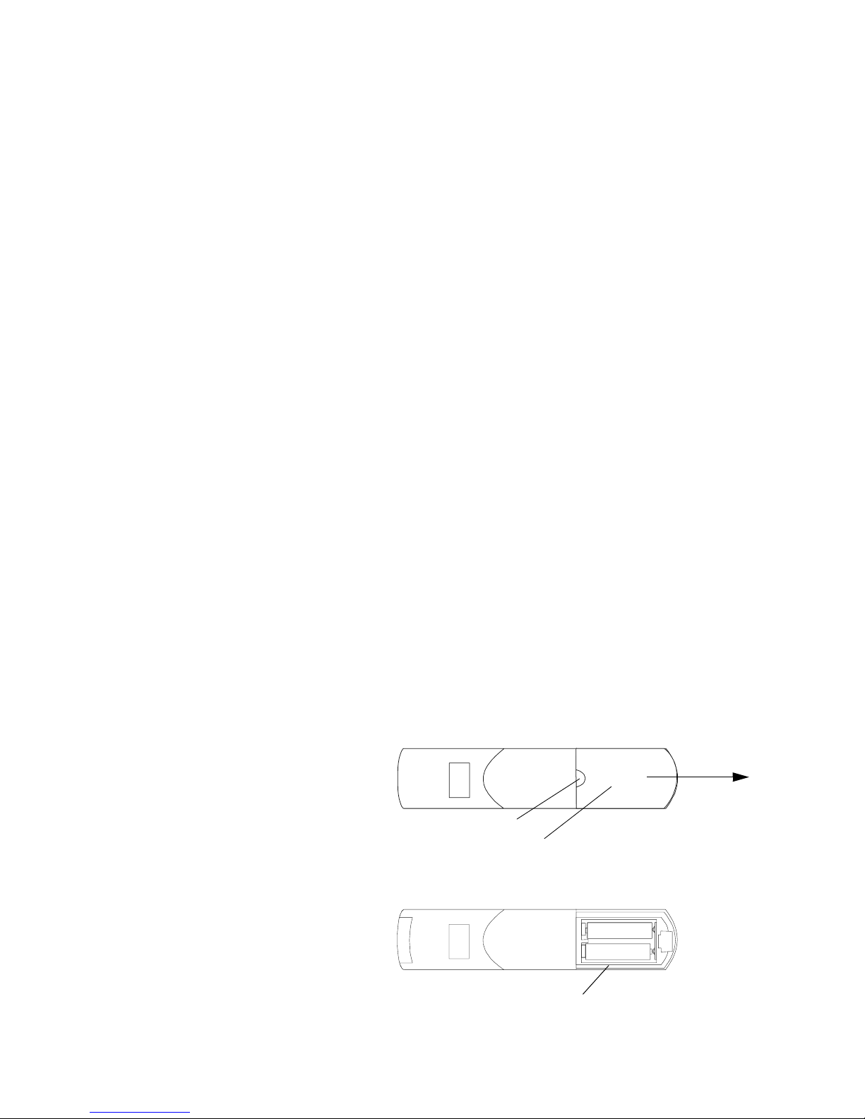
REPLACING REMOTE CONTROL BATTERIES
1. Remove the battery compartment cover by holding the remote control with its
back facing you, then pressing the battery cover at the thumb depression and sliding it off in the direction shown in the illustration below.
2. Install two 1.5V AA alkaline batteries, aligning positive and negative terminals
according to the diagrams in the battery compartment.
3. Replace the remote control battery cover, snapping it into place.
Thumb Depression
Battery Compartment Cover
+
-
+
-
Battery Compartment
Page 33

33
ADVANCED USE
Y ou may need the information in this section if you want to change the default settings
that were set up by your NSP or reprogram your remote control because it is not working correctly.
Note: Y our NSP programs your RG2200 and remote control when your system is first
connected. The NSP also programs the same Gateway ID (this is the ID of your
RG2200) into all the remote controls in your home. If there is more than one RG2200
in your home, your NSP programs the Gateway ID into the remote controls that communicate with a specific RG2200.
CHANGING OR PROGRAMMING SETTINGS
On-screen programming, using the remote control and the front-panel buttons of the
RG2200, allows you to do the following tasks:
• Determine the Gateway ID
• Set the Gateway ID
• Determine the Remote Control ID
• Set the Remote Control ID
• Program TV Code
• Scan TV Codes
Page 34

34
•Verify TV Codes
• Verify the TV RF channel
• Set the Display Language
• Set the Closed Captioning and Teletext
• Set the Secondary Audio
• Set the EADS (Emergency Alert Device Support) display
DETERMINING THE GATEWAY ID
Check, ”Write Your Remote Control and Other IDs Here” on page 13. Your NSP may
have already written down the Gateway’s ID. If the ID has not been written down, perform the following steps.
1. Press the SETUP button on the front panel of the RG2200. (See “Using Your
RG2200” on page 16 for an illustration and description of this button and other
buttons on the RG2200s.)
Page 35
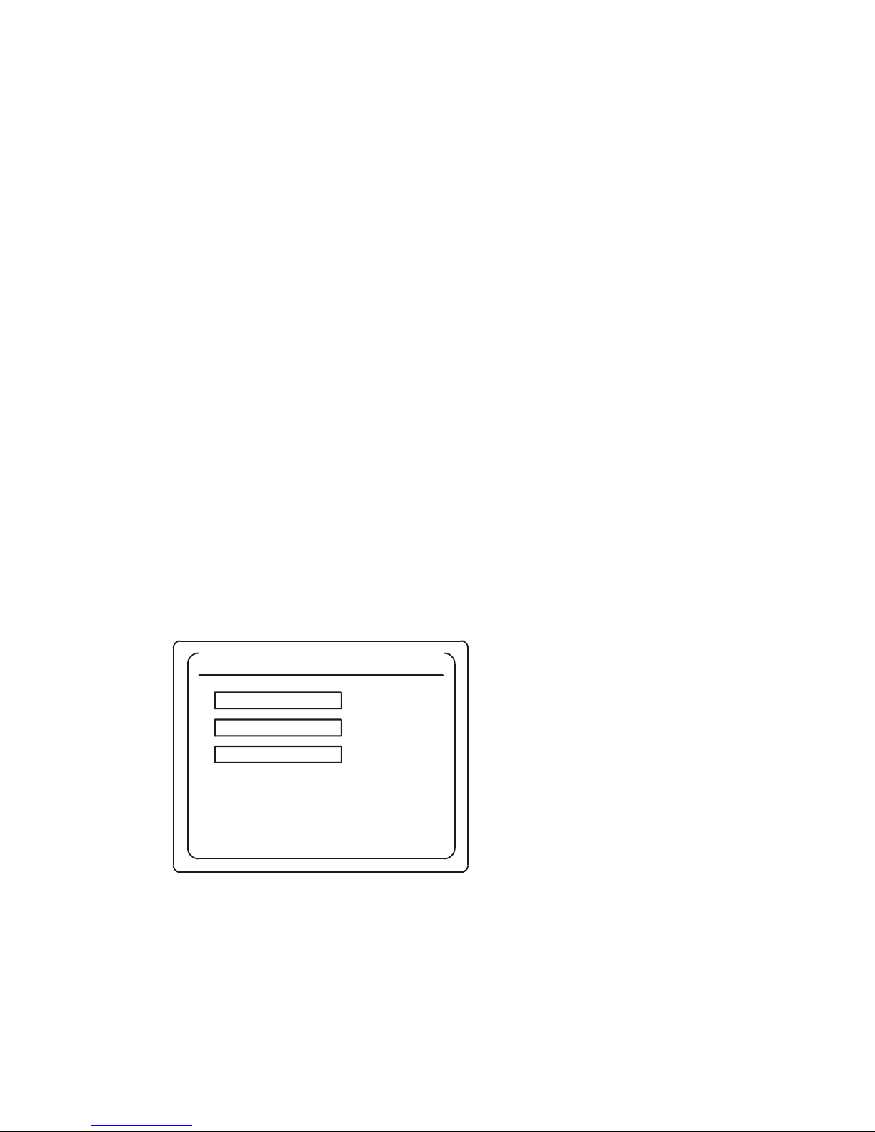
35
The Gateway Menu screen will be displayed on your TV.
2. Use the down arrow on your remote control to scroll down to Remote Control
Setup.
3. Press SELECT on your RG2200 or your remote.
Gateway Menu
SEP 3 3:22 PM
Use and , then press SELECT
Use EXIT to return to program viewing
!"
TV Setup
Remote Control Se tup
Exit
Page 36
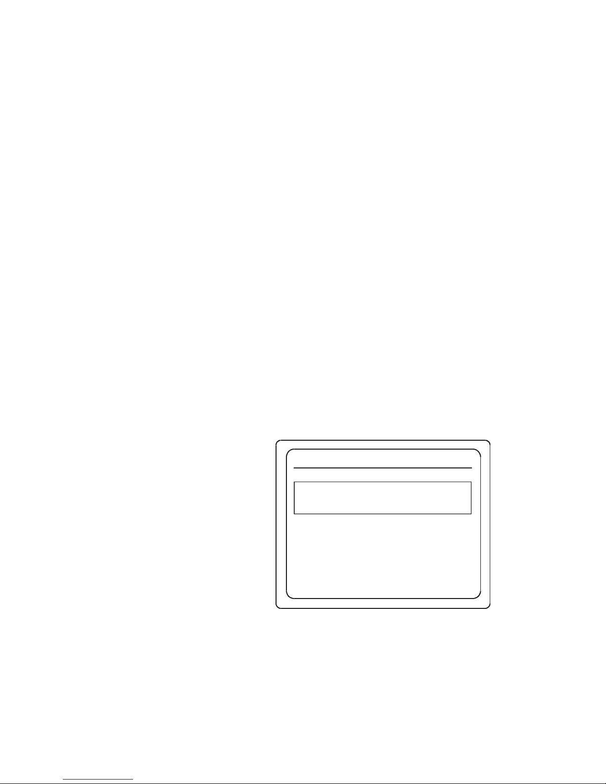
36
The Remote Control Setup screen will been displayed.
4. Press PPV on your remote control.
Remote Control Setup
SEP 3 3:22 PM
Press PPV on Remote now
Press EXIT to return to the main menu.
Page 37
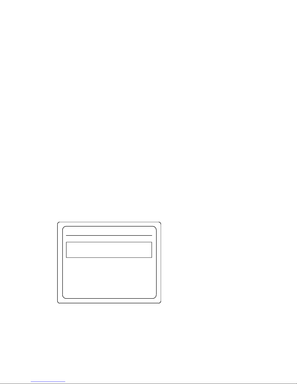
37
A list is displayed in the central box that shows the ID for the remote, what TV this
remote controls, and the Gateway ID.
If the Gateway ID programmed into your does not match the Gateway ID of the
RG2200, the system prompts you to reset the Gateway ID.
For future reference, write down the Gateway ID number displayed in ”Write Your
Remote Control and Other IDs Here” on page 13.
5. Press EXIT twice on your remote to exit the Remote Control Setup and Gateway
Menus.
Remote Control Setup
SEP 3 3:22 PM
Press PPV on Remote now
Remote ID for this Remote is:
The Gateway ID is set to:
1
Set to Control TV:
1 (Ch 6)
222
Press EXIT to return to the ma in men u.
Page 38
38
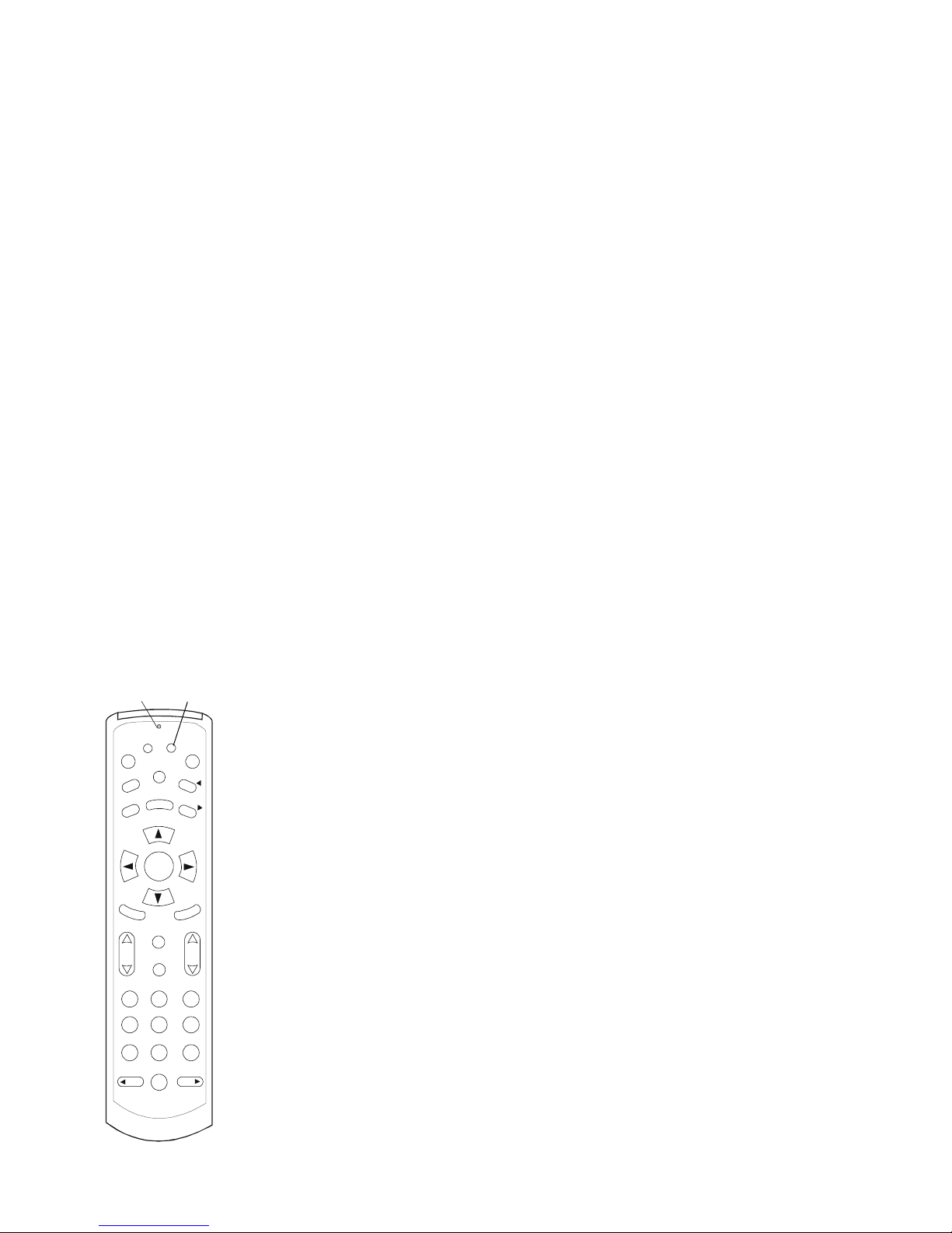
SETTING THE GATEWAY ID
1. Press the B button and hold it down until the LED at the top of the remote flashes
rapidly.
2. Release the B button.
3. Enter the following three-button sequence: 7-8-9.
The remote is now in programming mode. You can set the GATEWAY ID.
4. Enter the 3-digit code assigned to your RG2200.
The valid range is 004 - 255. You must enter a number with 3-digits, even if it con-
tains leading zeroes. Examples of valid Gateway ID numbers are: 009, 012, 124,
or 255.
If you did not enter the Gateway ID correctly, the following occurs:
• The LED is turned off and the remote control returns to normal operation. Return
to the steps at the beginning of this section.
Y ou can verify your Gateway ID by returning to ”Determining the Gateway ID” on page
34 and performing the listed steps.
GUIDE
SELECT
V
O
L
C
H
A
N
M
E
N
U
B
A
12 3
45 6
78 9
0
DAY
DAY
F
A
V
L
AST
C
H
MUTE
INFO
E
X
I
T
C
A
LL
I
D
P
P
V
P
O
W
E
R
P
A
G
E
P
A
G
E
LED B button
Page 39
39
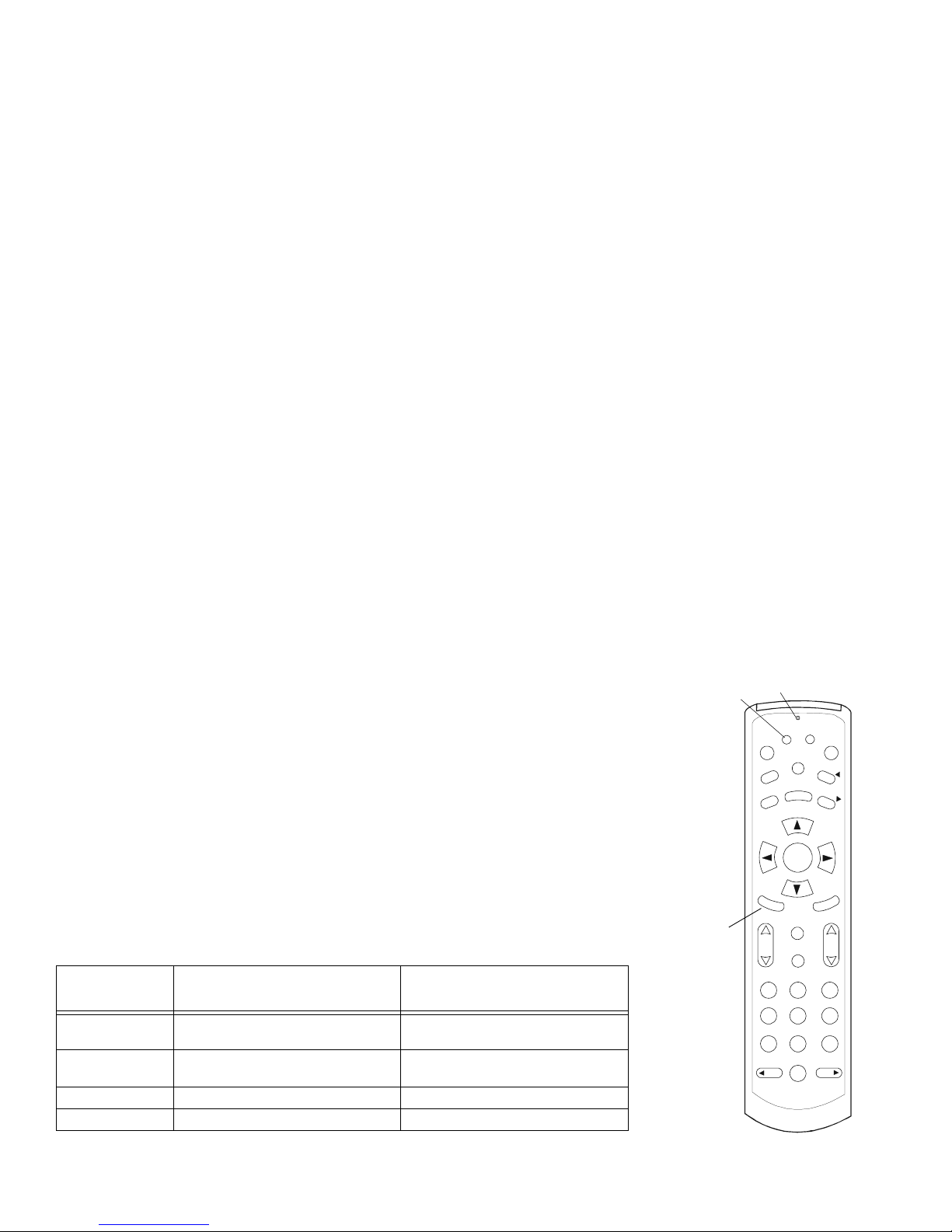
DETERMINING THE REMOTE CONTROL ID
1. Press the A button and hold it down until the LED at the top of the remote flashes
rapidly.
2. Press the FAV button and watch the LED.
Following are the sequences of flashing that indicate how your remote control ID is
programmed.
A short burst of flickering indicates a 0 (zero). The number of longer, steady blinks
indicates a non-zero digit, such as the following.
<pause> <long blink> <long blink> <long blink> indicates a “3.”
After blinking, the remote returns to normal operation.
G
UIDE
S
ELECT
V
O
L
C
H
A
N
M
E
N
U
B
A
1
2
3
4
5
678
9
0
DAY
D
AY
F
A
V
L
AST
C
H
M
UTE
I
NFO
E
X
I
T
C
A
LL
I
D
P
P
V
P
O
W
E
R
P
A
G
E
P
A
G
E
LED
A button
FAV
Number of
flashes
Remote Control ID Mode
Rapid flickering For TV1, which is in the same room
as your RG2200
IR (Infra Red)
1 Remote TV1: Primary TV is in a differ-
ent room than the RG2200.
UHF (ultra high frequency)
2 Remote TV2. UHF
3 Remote TV3 (VDSL only) UHF
Page 40
40
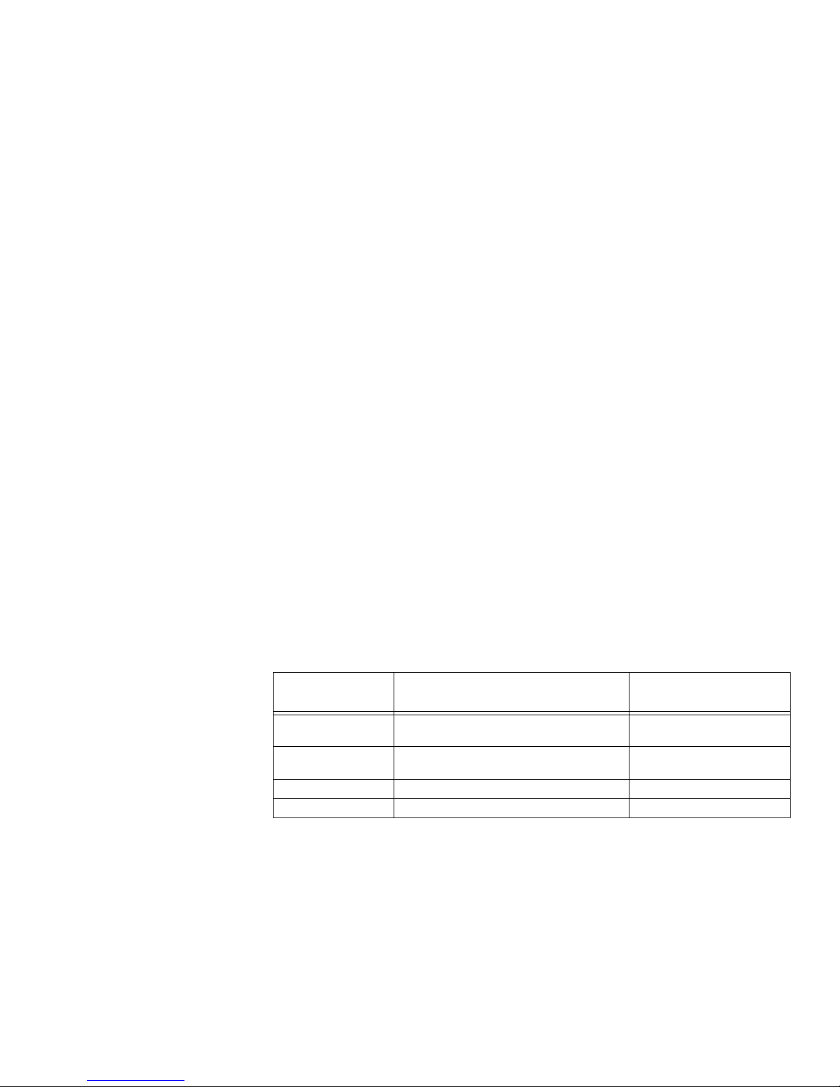
SETTING THE REMOTE CONTROL ID
Your NSP uses the following table when programming your remote control ID to work
with each TV in your household. You may use it, too.
Remote Control
ID
Operates TV Mode
0 Local TV1--TV in same room as RG. The
remote is set to operate in IR mode.
IR
1 Remote TV1--TV in a different room than the
RG.
UHF
2 TV2 (remote TV). UHF
3 TV3 (3 band models only). UHF
Page 41
41
T
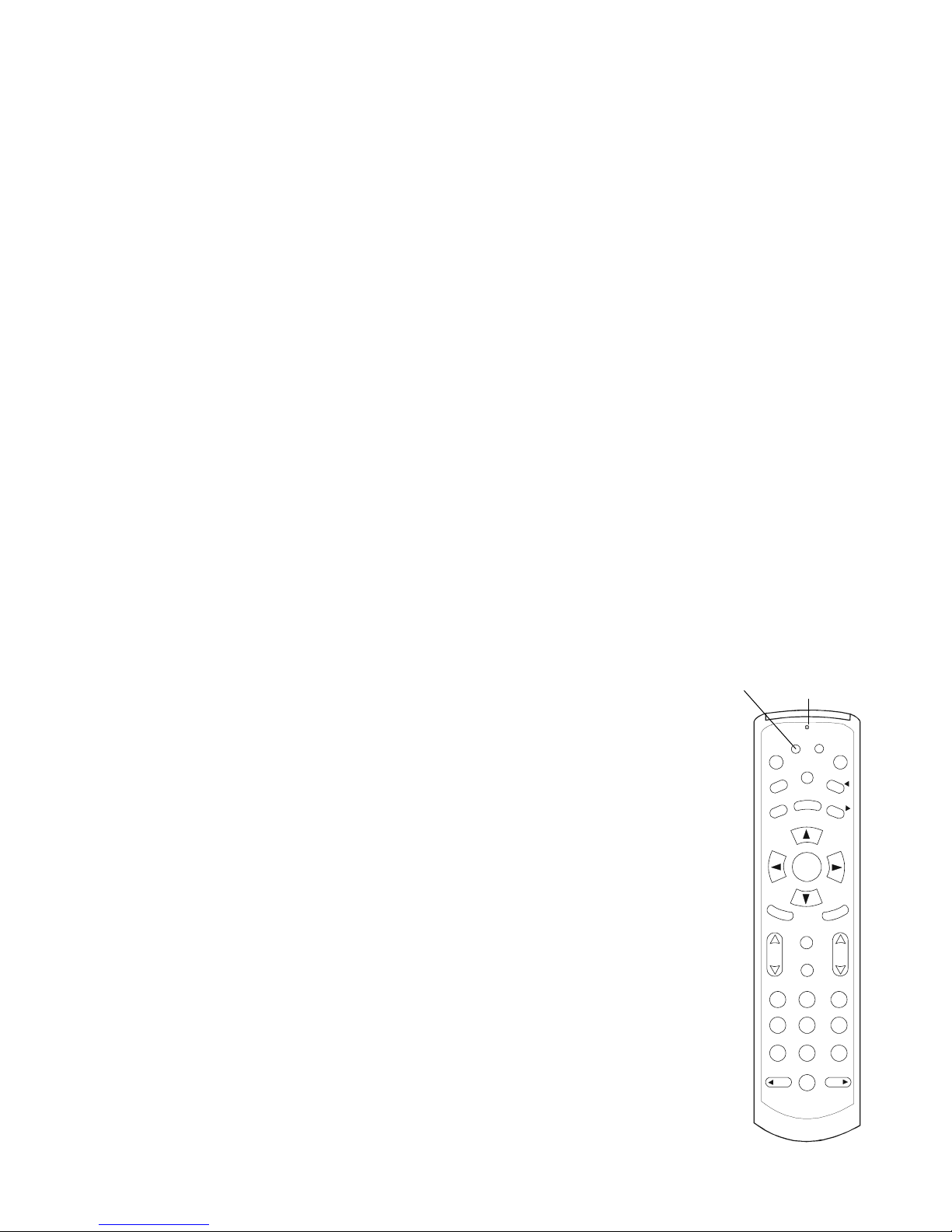
O PROGRAM THE REMOTE CONTROL ID, DO THE FOLLOWING.
1. Press and continue to hold the A button until the LED at the top of the remote
flashes rapidly.
2. Enter the following three-digit sequence: 7-8-9.
The remote is now in programming mode.
If you entered an invalid sequence or a 20-second lapse in button presses occurs, the
LED turns off and the remote control returns to standard operation.
3. Enter the single-digit remote control ID from the table on page 40.
Note: Valid single-digit codes are 0, 1, 2 (and 3, with 3 band models).
If you correctly entered the single-digit code, the LED flashes on and off and then
remains off.
Once you have figured out the remote control ID, write 0, 1, 2, or 3 on a label and
place this on the TV and the remote to help you identify the TV and the remote to
which it is assigned. Your Network Service Provider may have already done this.
You may repeat this procedure for each remote control.
G
UIDE
S
ELECT
V
O
L
C
H
A
N
M
E
N
U
B
A
1
2
3
4
5
678
9
0
DAY
D
AY
F
A
V
L
AST
C
H
M
UTE
I
NFO
E
X
I
T
C
A
LL
I
D
P
P
V
P
O
W
E
R
P
A
G
E
P
A
G
E
LEDA button
Page 42
42
PROGRAMMING THE TV CODE
Your Network Service Provider programs each remote control to work with one TV by
way of a TV code. The TV Code is a specific code for each brand and model of TV.
When a TV code is set, the remote control is able to address the specific signaling
requirements for that TV.
The TV codes can be programmed manually, or they can be scanned as described
below. TV codes are listed in ”TV Codes” on page 77.
If your NSP has programmed this for you, you will need to program the TV code, or
model information, into the remote control in order to operate your TV.
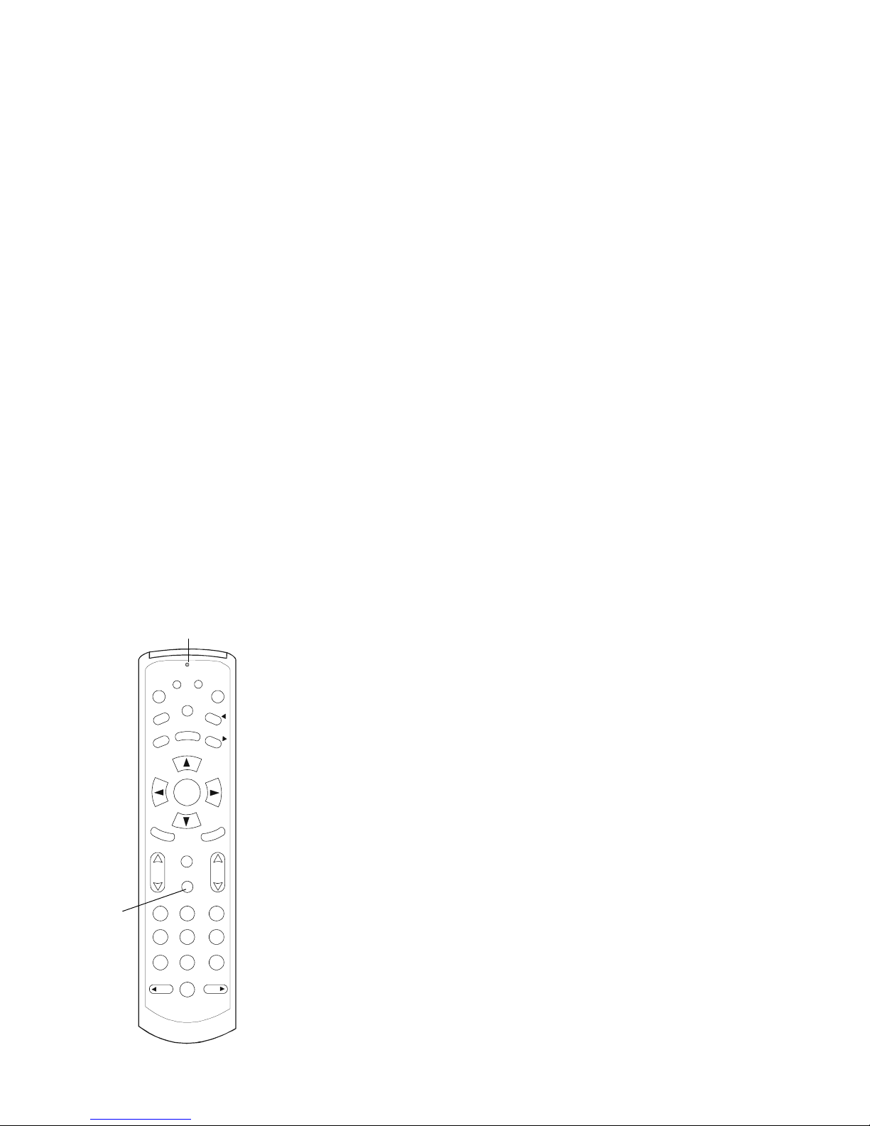
1. Press the MUTE button and hold it down until the LED at the top of the remote
control flashes rapidly.
2. While the LED button is flashing, enter the three digit code that corresponds to the
brand name of the TV. See “TV Codes” on page 77.
If the code is valid, the LED will flash on and off three times and then remain off.
If an invalid code is entered or a 20 second lapse in button presses occurs, the LED
will turn off and the remote control will return to normal operation. You will need to
repeat the above procedure to program the TV code.
GUIDE
SELECT
V
O
L
C
H
A
N
M
E
N
U
B
A
12 3
45 6
78 9
0
DAY
DAY
F
A
V
L
AS
T
C
H
MUTE
INFO
E
X
I
T
C
A
LL
I
D
P
P
V
P
O
W
E
R
P
A
G
E
P
A
G
E
LED
MUTE
Page 43

43
PROGRAMMING THE REMOTE USING CODE SEARCH METHOD
You can obtain TV codes by using the search method. To do this:
1. Press the MUTE button and hold it down until the LED at the top of the remote
control flashes rapidly.
2. Press the POWER button. The LED will light up and remain solidly lit.
3. Press the up arrow to scan through all TV codes. When you reach the correct TV
code, the TV will automatically turn on, or off if it was previously on. Note that the
LED will flash rapidly once you have scanned through all the codes.
4. Press the SELECT button to store the TV code. The LED flashes rapidly, then
stops, indicating that the TV code has been stored.
5. Repeat procedure for each remote control.
6. If you press the up arrow too rapidly, you may pass the TV code before the time
the TV turns on or off. If you are not sure you are storing the correct TV code,
press the down
arrow slowly to cycle back through codes that have been previ-
ously scanned.
7. When the TV turns off, or on if it was previously off, press SELECT at that point to
store the TV code.
VERIFYING THE TV CODES
1. Press the MUTE button and hold it down until the LED at the top of the remote
control flashes rapidly.
Page 44

44
2. Press the FAV button and observe the LED. The TV code will be indicated by a
blink sequence for each number. For example, code 130 would show as the following:
<pause> <long blink> <off> (represents 1)
<pause> <long blink> <long blink> <long blink><off> (represents 3)
<pause> <short burst of flickering blinks> <off> (represents 0)
VERIFYING AND SETTING OTHER FEATURES
The TV Setup menu allows you read the TV RF settings, as well as set Secondary
Audio, Display Language and the EADS display. These settings are accessed in the
TV Setup Menu.
ACCESSING THE TV SETUP MENU
To access TV Setup Menu:
1. Press the SETUP button on the front panel of the RG2200.
Page 45
45
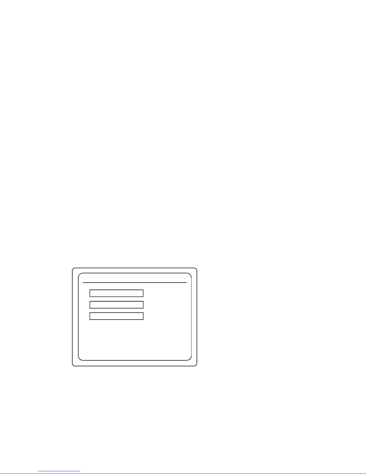
The Gateway Menu is displayed on your TV screen.
2. Use the down or up arrow on the RG2200 or the remote to highlight TV Setup.
3. Press the SELECT button on the RG2200 or the remote control.
Gateway Menu
SEP 3 3:22 PM
Use and , then press SELECT
Use EXIT to return to program viewing
!"
TV Setup
Remote Control Setup
Exit
Page 46
46
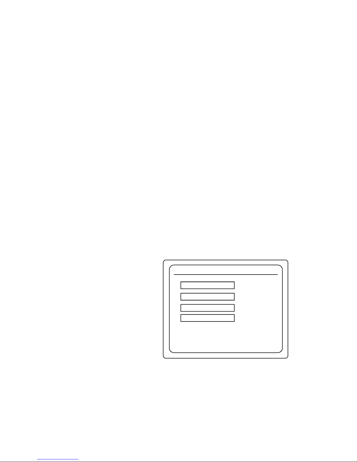
The TV Setup menu is displayed on your TV screen.
Note: The SELECT button on the remote control opens the Gateway menu only on
the TV/Source that the remote control is programmed to operate. If you press SELECT and nothing happens, you need to determine which TV the remote operates.
See “Determining th e Remote Control ID” on page 39.
VERIFYING THE TV (RF) SETTING
1. Press SETUP button on the RG2200 front panel.
The Gateway Menu is displayed.
TV Setup Menu
SEP 3 3:22 PM
Use and , then press SELECT
Use EXIT to return to program viewing
!"
TV1
TV2
TV3
Exit
Page 47
47
2. Use the down or up arrow on the RG2200 or the remote control to scroll to TV
Setup.
3. Press SELECT.
The TV Setup Menu will be displayed on your TV.
4. Use the down or up arrow on the remote control to highlight the TV you want to
examine.
5. Press SELECT.
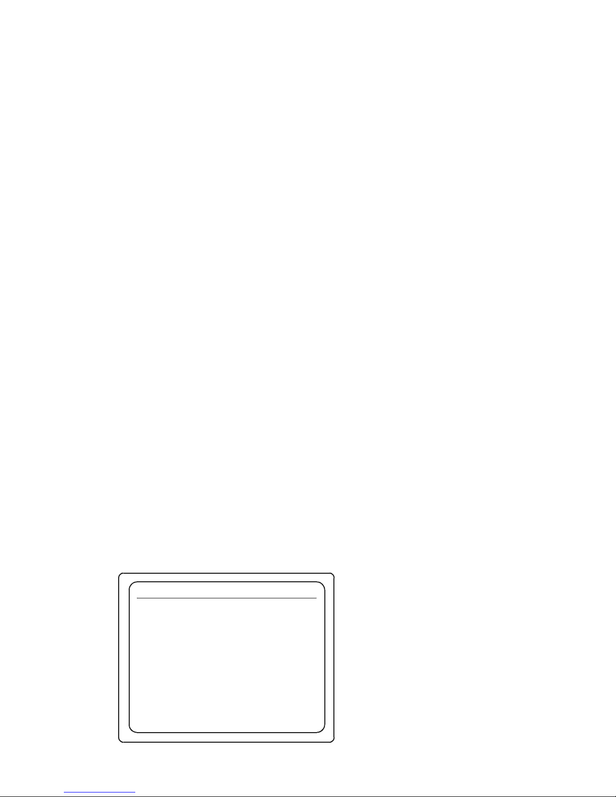
For example, if you selected TV1, the Setup 1 menu will be displayed.
Setup 1
SEP 3 3:22 PM
TV (RF) Channel
Use and to select item
Use EXIT to return to previous menu
!"
Use and to change value
#$
Secondary Audio
Display Language
Emergency Alert Device Support
6
Spanish
English
OFF
Video Format
NTSC
Page 48

48
The selected RF setting is displayed, in this case channel 6 has been selected.
Note: Your Network Service Provider sets up the initial RF channel settings and your
TV to provide program channels by programming the output to a specific RF channel.
If you need to change the RF channel settings, it is recommended that you call your
NSP to do this for you.
6. Press the EXIT button twice to exit back to the program screen.
SECONDARY AUDIO: SPECIFYING A PREFERRED LANGUAGE
Secondary audio allows you to select a preferred language for each TV.
Your NSP may deliver up to four audio programs with each video program. Your NSP
may specify, for example, English as the first language, Spanish as the second,
French as the third and Chinese as the fourth. If the preferred language is available,
the alternate language audio track will be transmitted with the video program.
If a selected language is not provided on a particular channel, the RG2200 defaults to
the primary language provided with the program. For example, if you are watching a
Spanish-only channel, Spanish audio is played regardless of the Secondary Audio
Display option.
1. Press the SETUP button on the RG2200.
The Gateway Menu is displayed.
Page 49

49
2. Use the up and down arrow buttons to highlight the TV Setup option.
3. Press SELECT.
The TV Setup menu is displayed.
4. Use the up and down arrow buttons to highlight the TV that you want to modify
(TV1, 2 or 3).
5. Press SELECT.
The Setup TV# menu is displayed.
6. Use the up or down arrow button on your RG2200 or remote control to highlight
Secondary Audio.
7. Use the left and right arrow buttons to cycle through the alternate languages until
the langu age you want is displayed.
8. Press the EXIT button twice to return to the program screen.
DISPLAY LANGUAGE
1. Press the SETUP button on the RG2200.
The Gateway Menu is displayed.
2. Use the up and down arrow buttons to highlight the TV Setup option.
3. Press SELECT.
Page 50

50
The TV Setup menu is displayed.
4. Use the up and down arrow buttons to highlight the TV that you want to modify
(TV1, 2 or 3).
5. Press SELECT.
The Setup TV# menu is displayed.
6. Use the up or down arrow button on your RG2200 or remote control to highlight
Display Language.
7. Press the right arrow button to highlight the default language, which was English
in the previous examples.
8. Continue to press the right arrow button in the language field until the language
you want appears. Available languages are English, Spanish, French, and Norwegian.
9. When you have selected the preferred language, press EXIT to return to the Main
Menu screen.
CLOSED CAPTIONING
The RG2200 supports closed captioning capability. Refer to your TV User’s Guide for
instructions on how to use closed captioning.
Page 51

51
TELETEXT
Some televisions in European countries support Teletext. Teletext data is passed
through the RG2200 to your television. Refer to your TV’s User’s Guide for instructions on how to use Te lete xt .
EADS (EMERGENCY ALERT DEVICE SUPPORT)
Your NSP enables the EADS (Emergency Alert Device Support) on each TV when
service is established. If you would like to disable or change the EADS settings, use
the following directio ns:
1. Press the SETUP button on the RG2200.
The Gateway Menu is displayed.
2. Use the up and down arrow buttons to highlight the TV Setup option.
3. Press SELECT.
The TV Setup menu is displayed.
4. Use the up and down arrow buttons to highlight the TV/Source that you want to
modify.
5. Press SELECT.
The Setup (TV#) menu appears on your TV screen.
Page 52
52
6. Use the up and down arrows to highlight Emergency Alert Device Support.
7. Press the right or left arrow buttons to enable/disable Emergency Alert Device
Support.
8. Press EXIT to return to the previous menu.
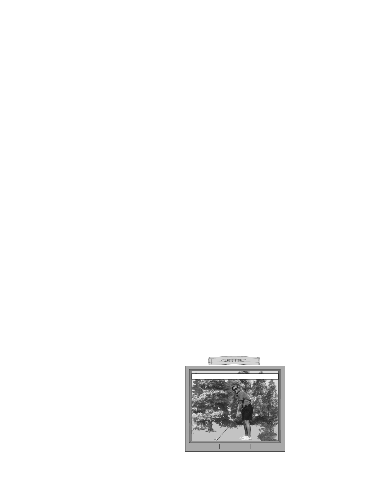
If Emergency Alert Device Support is enabled, the following occurs for all EAS (Emer-
gency Alert System) broadcasts:
• You hear a two-tone attention signal during Emergency Alert broadcasts.
• The RG2200 automatically tunes your TV to the channel that is broadcasting the
EAS message.
• The emergency message appears at the top of your TV screen.
A
FLASH FLOOD WARNING HAS BEE
Page 53

53
If EADS is not enabled, one of the following occurs, depending on the type of EAS
broadcast:
• You hear a two-tone attention signal.
• A pop-up message appears on your TV screen to advise you of what type of
emergency has occurred and the channel you should tune for more information.
• The RG2200 automatically tunes your TV to the channel that is broadcasting the
EAS message.
Page 54
54
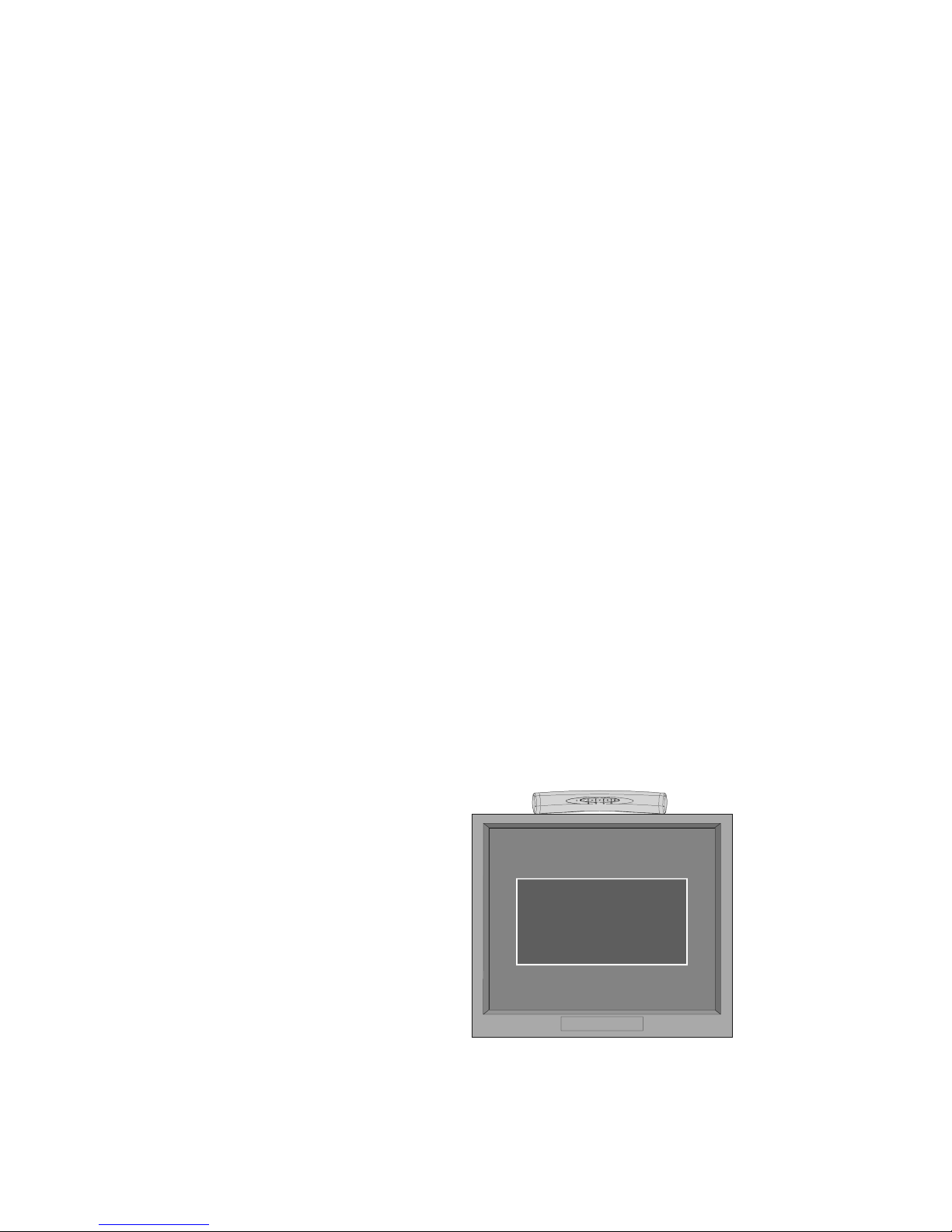
For national and required monthly testing alerts, the RG2200 automatically tunes your
TV to the EADS broadcast channel.
Flash Flood Warning
T
une to Channel 6 for information
Page 55

55
CONNECTING YOUR PC TO THE INTERNET
Important! Connecting your PC to the Internet and setting up the communications
protocols on your PC should be done by your NSP. The following illustrations are for
reference if you to move or replace your PC(s).
ETHERNET CONNECTIONS
Important! Although they appear identical, the CAT 5 cable that connects your
RG2200 to your NSP (Network Service Provider) may be wired differently than the RJ45 cable that connects your PC to the RG2200. Do not switch these two cables. If the
cables are switched, the network connection to your RG2200, or your Ethernet connection to your PC may not operate. It is recommended that you label the two cables
to avoid inadvertently switching them.
Page 56
56
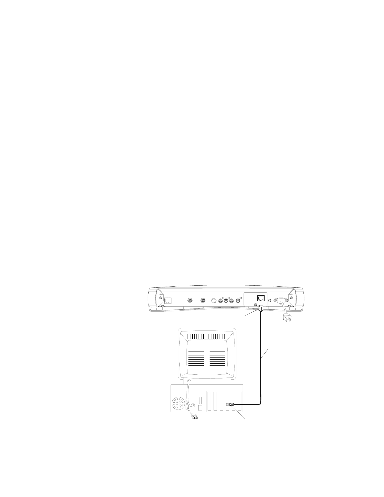
Single PC connected to the Internet through the RG2200
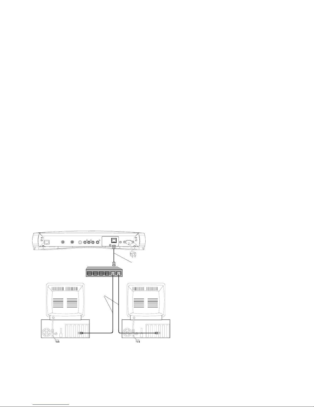
The RG2200 Ethernet output can connect to multiple PCs through the use of a hub.
Whether all PCs connected in this manner can be provided with Internet access service depends on your NSP.
AC-3
ETHERNET
AUDIO-RAUDIO-LS-VIDEOTV OUT
N
ETWORK IN/
TV OUT
NETWORK IN
IR
BLASTER
110-230 VAC
50-60 Hz
13A MAX
VIDEO
PC
CAT 5 Ethernet
cable
RJ-45
RJ-45
Page 57
57
Multiple PCs connected to the Internet through the RG2200.
AC-3
ETHERNET
AUDIO-RAUDIO-LS-VIDEOTV OUT
NETWOR K IN/
TV OUT
NETWOR K IN
IR
BLASTER
110-230 VAC
50-60 Hz
13A MAX
VIDEO
Ethernet hub
PC
PC
CAT5 Ethernet
cable
CAT5 Ethernet cable
Page 58

58
Page 59

59
CONFIGURATION EXAMPLES
Your Network Service Provider installs the RG2200 and connects all your electronic
devices to the RG2200. However, you may need the information in this section if you
ever want to do any of the following:
• Move existing devices to a different location
• Add new devices to your system
• Reconfigure existing connections
Note: The RG2200 should be located in the area with your primary TV (TV1) and
your home entertainment system.
User Tip: When you are
plugging your RG2200 in to a
VCR that has more than one
A V input, be sure to plug your
RG2200 into the default, or
primary input, which could be
called AV-1 or L-1. Consult
your VCR user’s manual.
When you rearrange your equipment, be sure to unplug and plug in your equipment in
the following order:
1. Unplug all electronic devices, including the TV, VCR, and RG2200.
2. Disconnect all cables between your electronic devices.
3. Make your planned changes.
4. Reconnect the cables between these devices.
5. After you have connected the cables, first plug in the RG2200.
Page 60
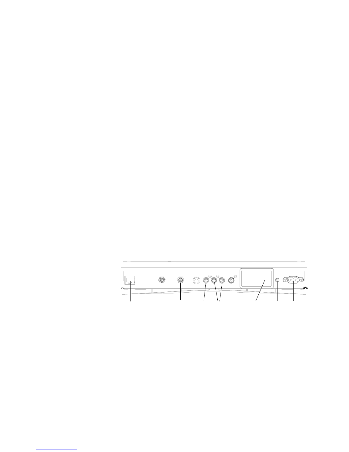
60
RG2200 back panel.
1. NETWORK IN.
2. NETWORK IN/TV OUT.
3. TV OUT.
4. S-VIDEO.
5. VIDEO (composite).
6. AUDIO L and AUDIO R.
7. DIGITAL AUDIO (Dolby Digital or AC-3 on S/PDIF connector).
8. Port cover for optional ETHERNET or HPNA (future) card.
9. IR BLASTER.
10. AC power.
234 6
7
5810
9
1
AC-3
A
UDIO-R
A
UDIO-L
S
-VID EOTV OUT
N
ETWORK IN/
TV OUT
NETWORK IN
IR
BLASTER
1
10-230 VAC
50-60 Hz
13A MAX
VIDEO
Page 61
61
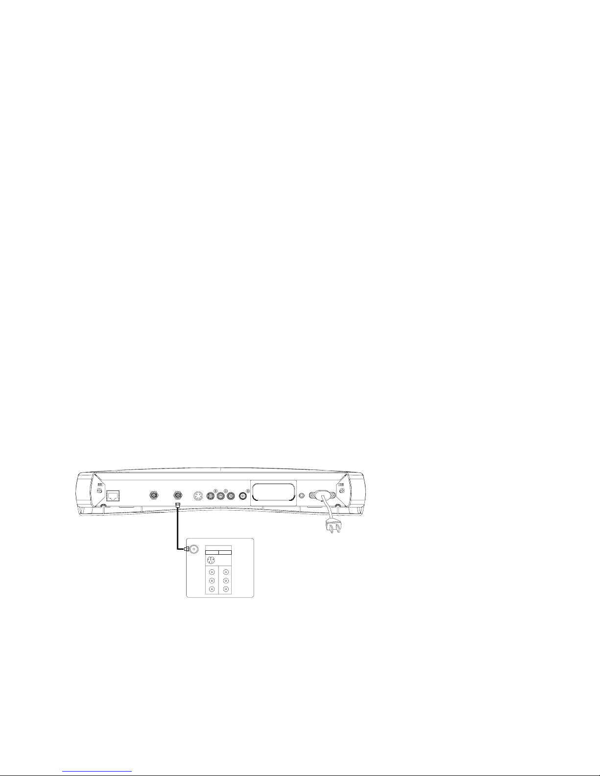
TV/VCR/AUDIO CONNECTIONS
TV OUT (VHF) to TV1.
AC-3AUDIO-RAUDIO-LS-VIDEOTV OUT
NETWORK IN/
TV OUT
NETWORK IN
IR
BLASTER
1
10-230 VAC
50-60 Hz
13A MAX
VIDEO
S-Video
VHF/UHF
IN
Video1 Video2
Video In
Audio L
Audio R
TV1
Page 62
62
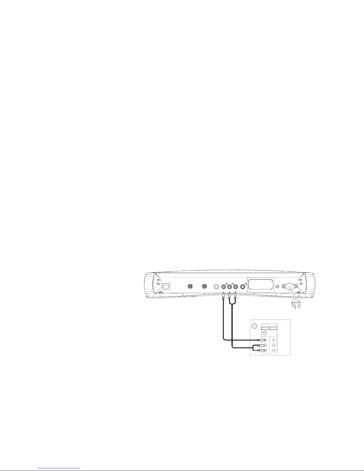
VIDEO (composite)/AUDIO-L/AUDIO-R to TV1.
AC-3AUDIO-RAUDIO-L
S
-VID EOTV OUT
N
ETWORK IN/
TV OUT
NETWORK IN
IR
BLASTER
110-230 VAC
50-60 Hz
13A MAX
VIDEO
S-Video
V
HF/UHF
IN
Video1 Video2
Video I n
Audio L
Audio R
TV1
Page 63
63
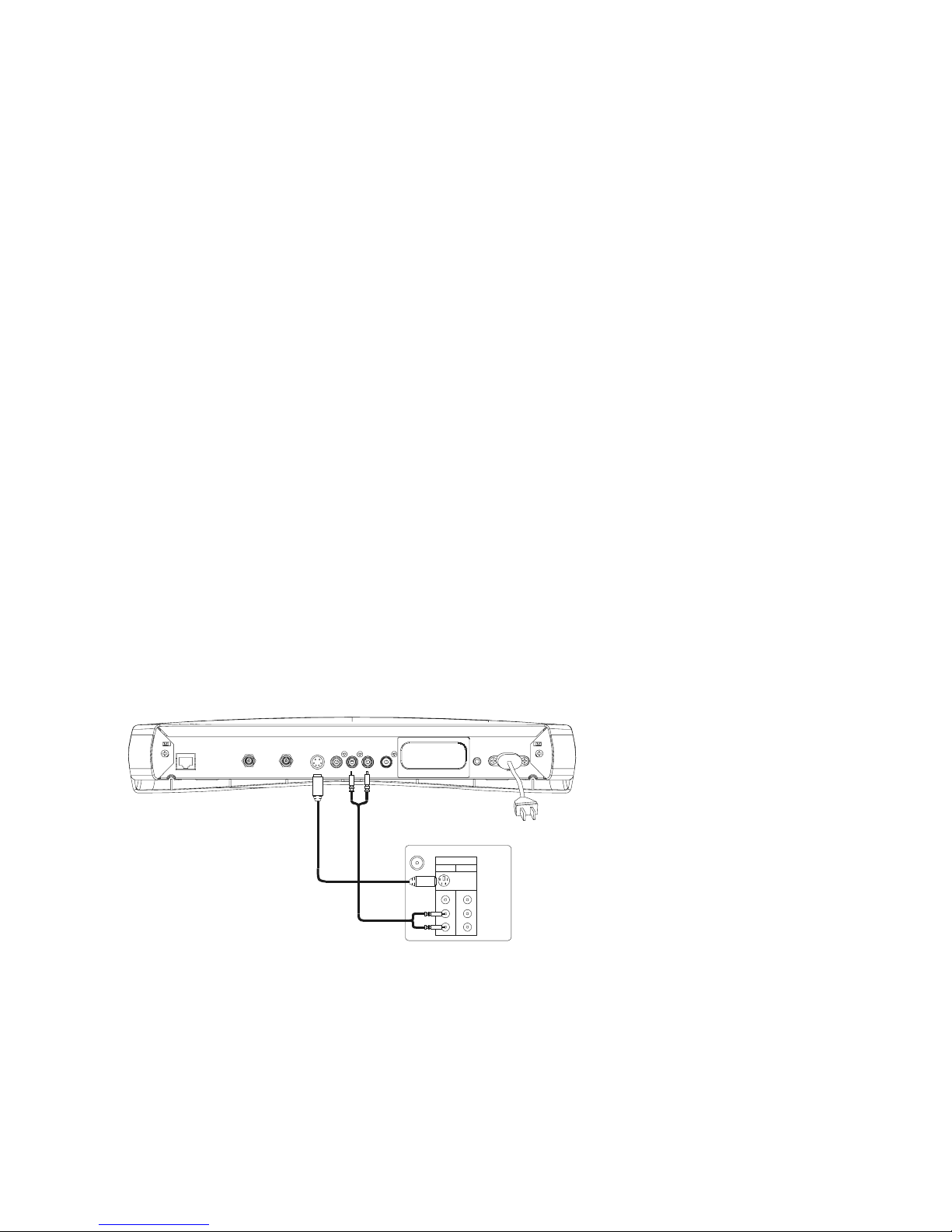
S-VIDEO/AUDIO-L/AUDIO-R to TV1.
AC-3AUDIO-RAUDIO-LS-VIDEOTV OUT
NETWORK IN/
TV OUT
NETWORK IN
IR
BLASTER
1
10-230 VAC
50-60 Hz
13A MAX
VIDEO
S
-Video
V
HF/UHF
IN
V
ideo1Video2
V
ideo In
Audio L
Audio R
TV1
Page 64
64
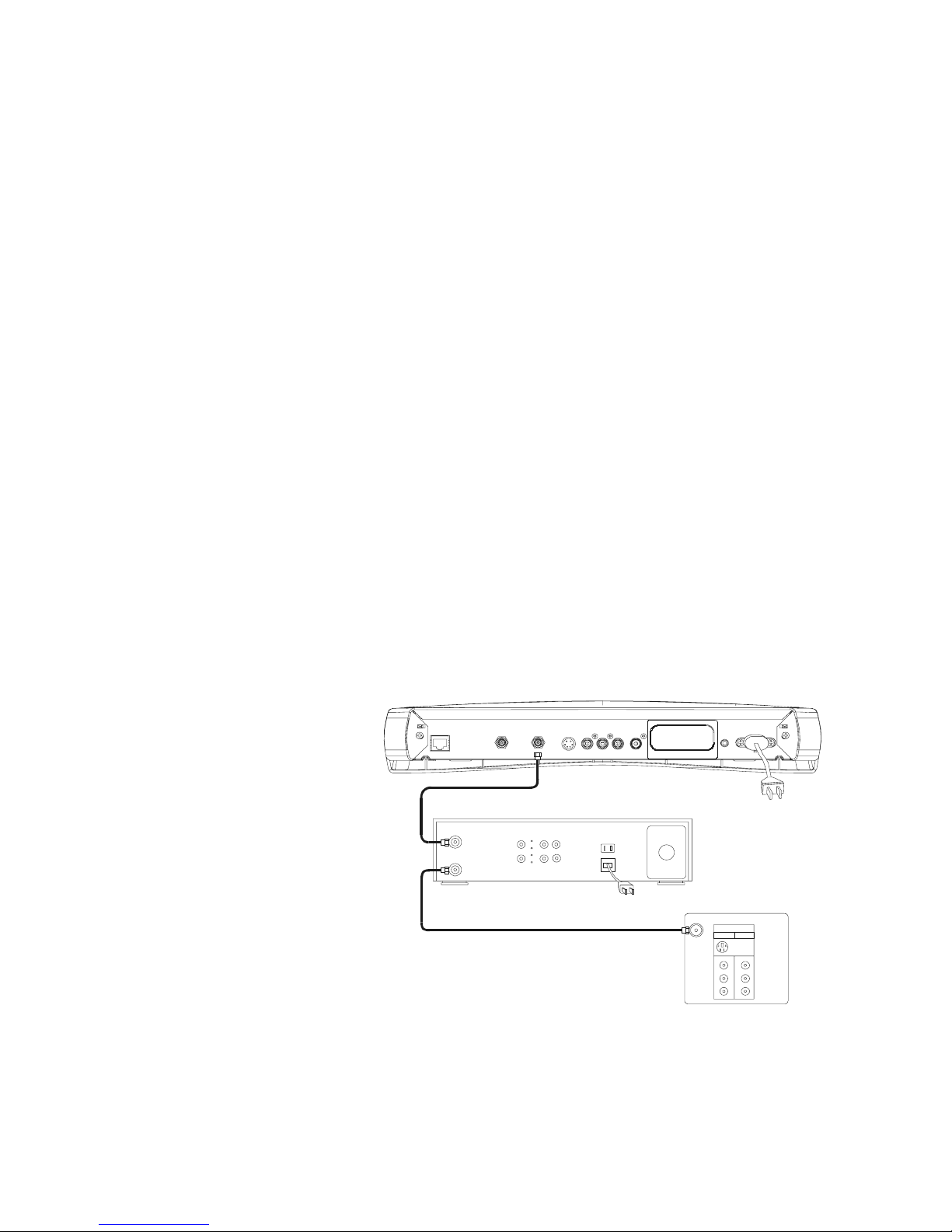
TV OUT (VHF) to VCR/TV1.
AC-3AUDIO-RAUDIO -L
S
-VIDEOTV OUT
N
ETWORK IN/
TV OUT
NETWORK IN
IR
BLASTER
110-230 VAC
50-60 Hz
13A MAX
VIDEO
S-Video
VHF/UHF
IN
Video1 Video2
Video In
Audio L
Audio R
OUT TO TV
ANTENNA IN
VCR
TV1
Page 65
65
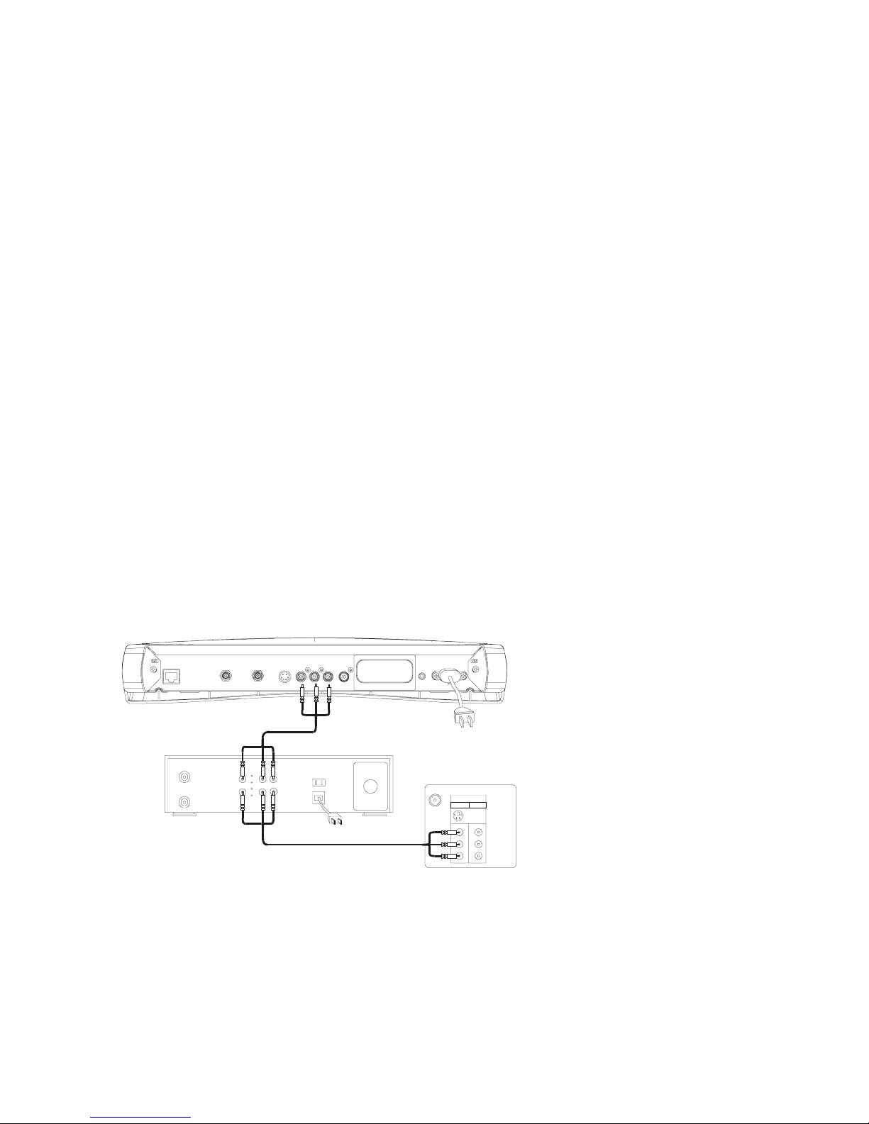
Composite VIDEO with AUDIO-L/AUDIO-R to VCR and TV1.
AC-3AUDIO-RAUDIO-L
S
-VIDEOTV OUT
NETWORK IN/
TV OUT
NETWORK IN
IR
BLASTER
1
10-230 VAC
50-60 Hz
13A MAX
VIDEO
S
-Video
V
HF/UHF
IN
V
ideo1Video2
V
ideo In
Audio L
Audio R
VIDEO OUT
VIDEO IN
AUDIO OUT
AUDIO IN
VCR
TV1
Page 66
66
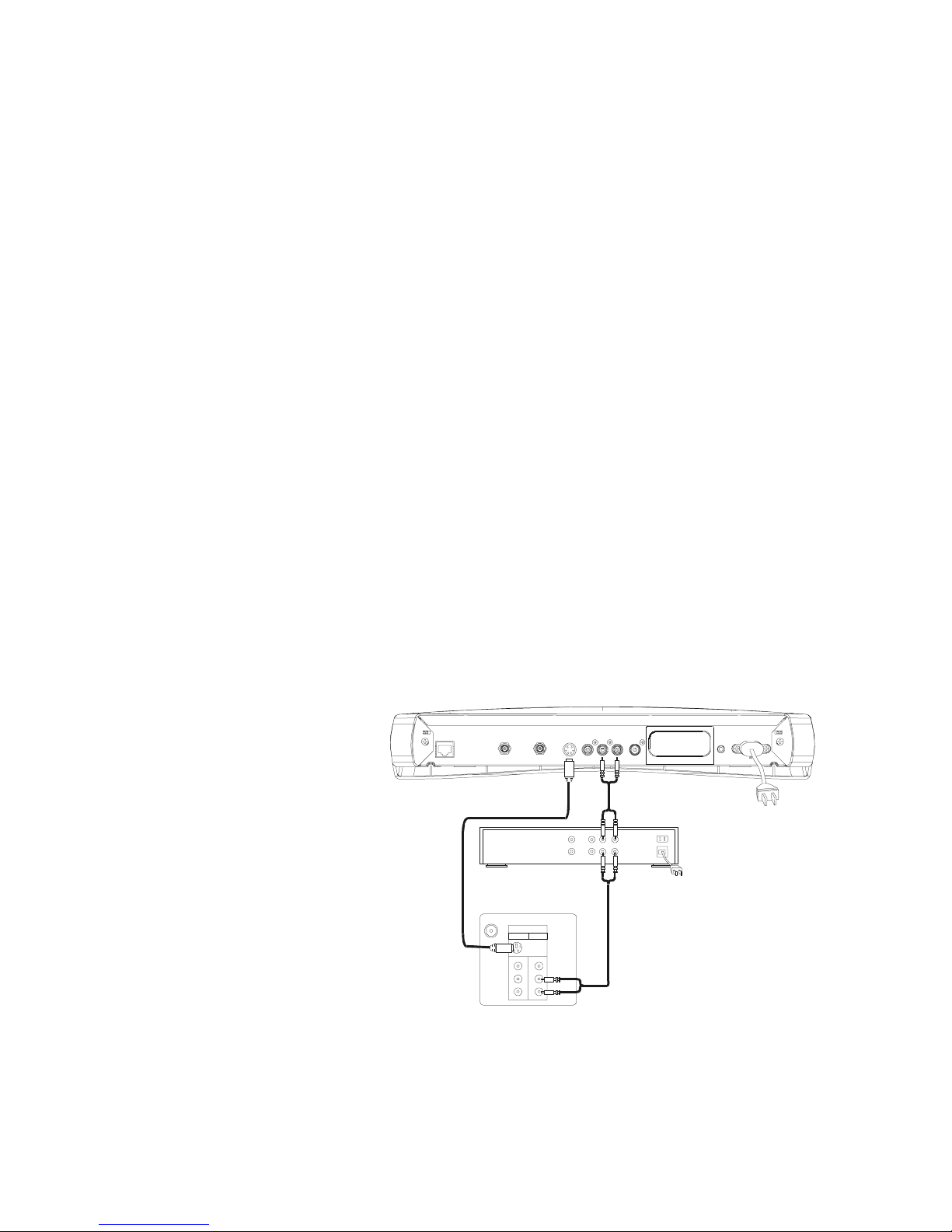
S-VIDEO and AUDIO-L/AUDIO-R to audio receiver and TV1.
AC-3AUDIO -RAUDIO-L
S
-VIDEOTV OUT
N
ETWO RK IN/
TV OUT
NETWORK I N
IR
BLASTER
110-230 VAC
50-60 Hz
13A MAX
VIDEO
S-Video
VHF/UHF
IN
Video1 Video2
Video In
Audio L
Audio R
AUDIO IN
A
UDIO OUT
TV1
audio receiver
Page 67
67
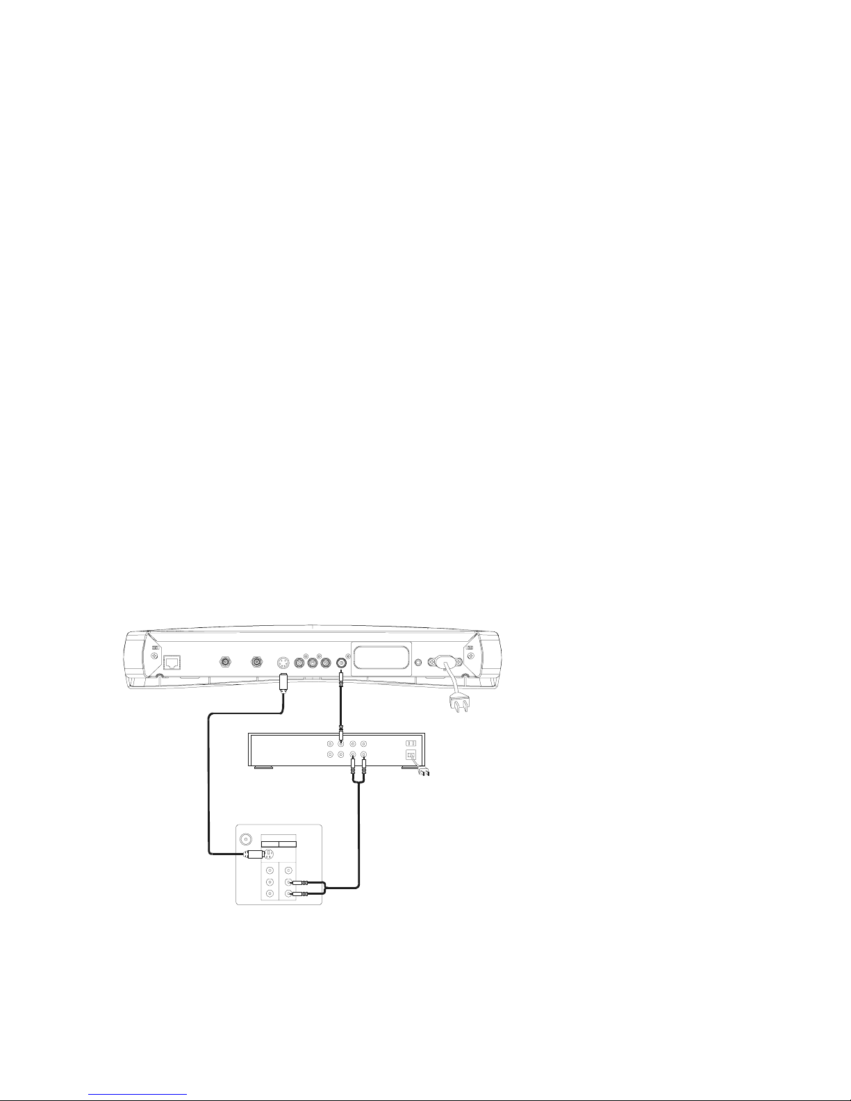
S-VIDEO/Digital Audio to audio receiver and TV1.
AC-3AUDIO- RAUDIO-LS-VIDEOTV OUT
NETWORK IN/
TV OUT
NETWORK I N
IR
BLASTER
1
10-230 VAC
50-60 Hz
13A MAX
VIDEO
S-Video
VHF/UHF
IN
Video1 Video2
Video In
Audio L
Audio R
A
UDIO IN
DIGITAL AUDIO IN
AUDIO OUT
audio receiver
TV1
Page 68
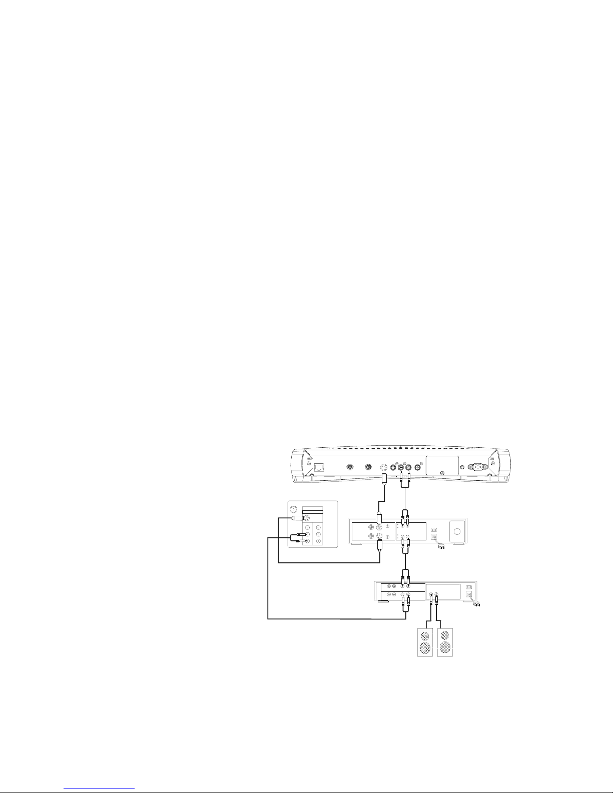
68
Basic home entertainment center.
AC-3AUDIO-RAUDIO-L
S
-VID EOTV OUT
N
ETWORK IN /
TV OUT
NETWOR K IN
IR
BLASTER
110-230 VAC
50-60 Hz
13A MAX
VIDEO
SPEAKER OUT
A
UDIO IN
A
UDIO OUT
VIDEO IN
VIDEO OUT
AUDIO IN
AUDIO OUT
LRLRL
R
L
R
S-Video
VHF/UHF
IN
Video1 Video2
Video Out
Audio L
Audio R
Video In
L
R
TV1
VCR
audio receiver
left speaker right speaker
Page 69
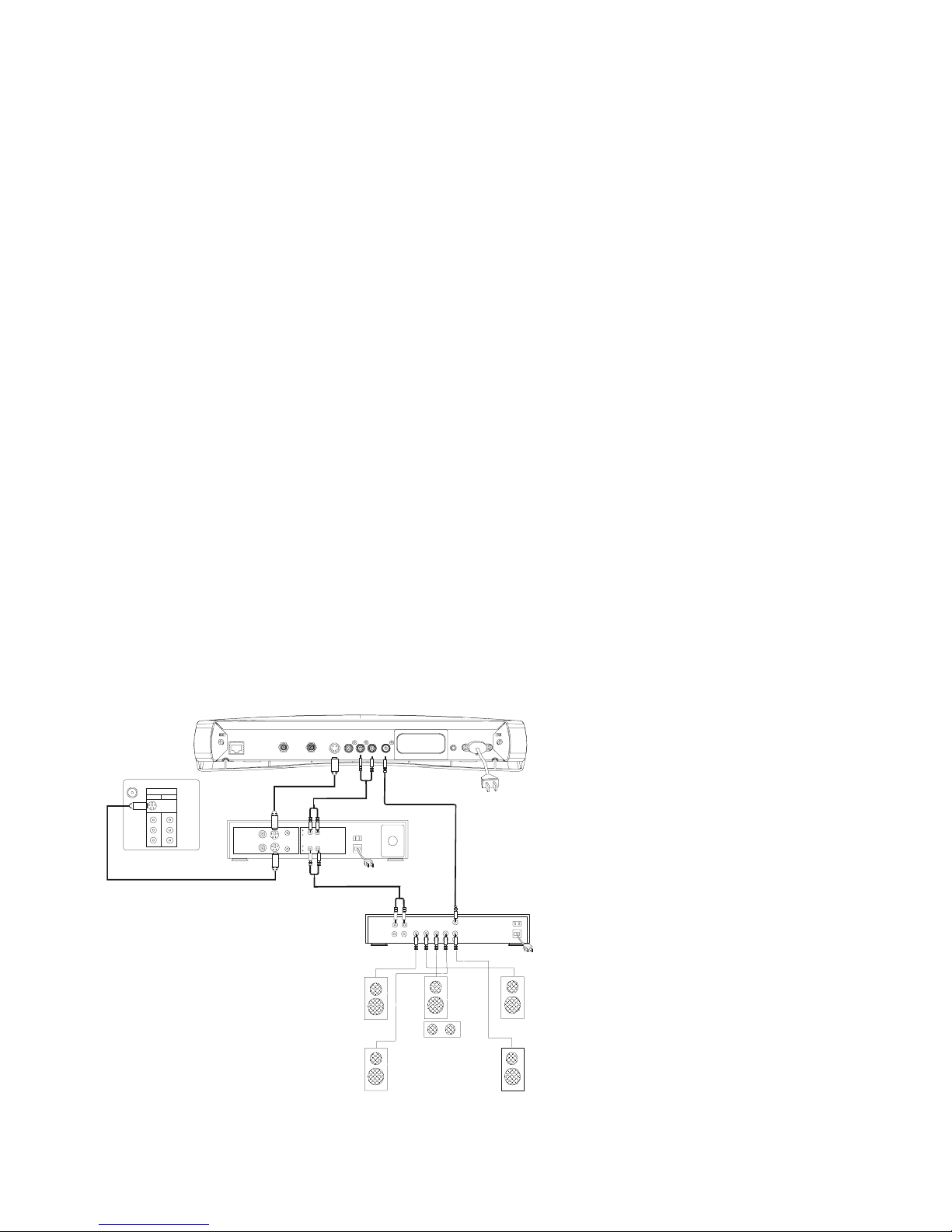
69
Advanced home entertainmen t cente r with Su rro und Sou nd (wi th Dolb y Dig ital 5.1
capability).
AC-3AUDIO-RAUDIO-LS-VIDEOTV OUT
NETWORK IN/
TV OUT
NETWORK IN
IR
BLASTER
1
10-230 VAC
50-60 Hz
13A MAX
VIDEO
D
IGITAL AUDIO IN
S
URROUND AUDI O OUT
F
RONT
C
ENTER
BACK
AUDIO OUT
S-Video
VHF/UHF
IN
Video1 Vi deo2
Video Out
Audio L
Audio R
Video In
AUDIO IN
AUDIO OUT
VIDEO IN
VIDEO OUT
AUDIO IN
VCR
TV1
audio receiver
left front
speaker
right front
speaker
right rear
speaker
left rear
speaker
woofer
center
speaker
Page 70
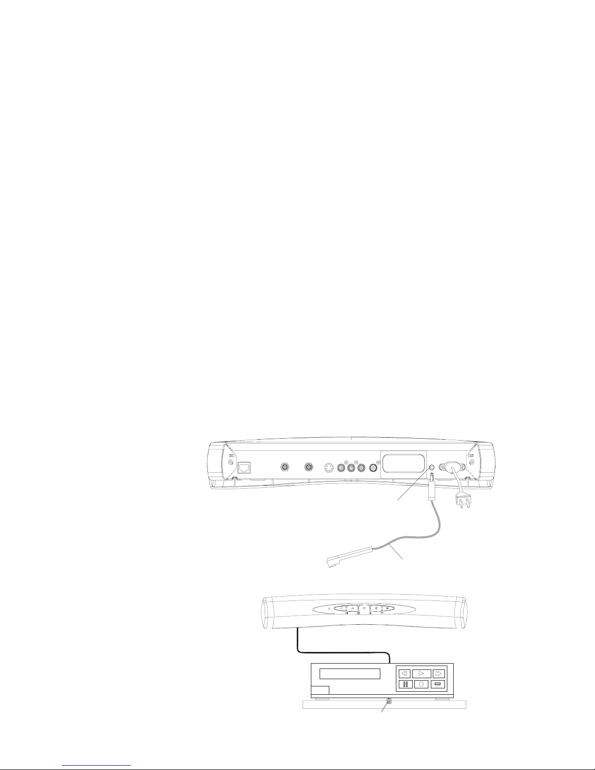
70
IR Blaster connection and posit ion ing .
VCR
IR Blaster
cable from IR
Blaster port
AC-3AUDIO-RAUDIO-L
S
-VIDEOTV OUT
N
ETWORK IN/
TV OUT
NETWORK IN
IR
BLASTER
110-230 VAC
50-60 Hz
13A MAX
VIDEO
IR Blaster port
IR Blaster
Page 71
71
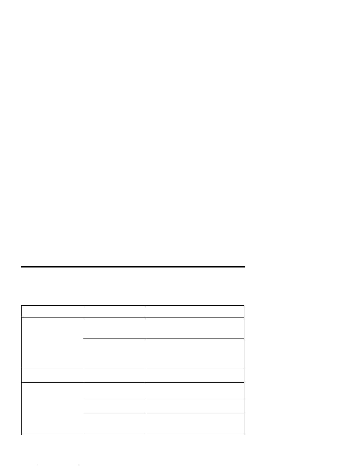
TROUBLESHOOTING
This section describes what to do if yo u r sy st em is no t wor kin g co rre ct l y. Study the fol lowing tables to find possible causes and solutions to the problem.
Problem Possible Cause Try This
Remote doesn’t work Dead batteries. Change the batteries in your remote
according to the instructions on page
32.
Obstruction between
the remote and the
RG2200 or IR
Transmitter.
Make sure that nothing is on or
blocking a clear line of sight between
the RG2200 and the remote.
Remote will not accept
programming changes
Weak batteries. Replace batteries and reprogram.
Remote will not
operate at secondary
viewing locations
Weak or dead
batteries.
Replace batteries.
Using wrong remo te for
that TV.
Check remote labe l to be sure you are
using correct remote control.
Obstruction between
the remote and the TV.
Make sure that nothing is on or
blocking a clear line of sight between
the TV and the remote.
Page 72
72
No sound MUTE is pressed on
the remote control.
Press MUTE on the remote to restore
volume level.
TV code not
programmed.
Refer to “Programming the TV Code”
on page 42.
No picture TV or RG2200 may not
be activated.
Refer to “Getting Started” on page 15.
Cable signal may not
be reaching your home.
Make sure all cables are connected
properly and that your TV is tuned to
the correct RF channel (for example
6,7, or 13) for the TV you are using
(TV-1, TV-2, or TV-3). If the baseband
video output on the RG2200 is
connected to the VIDEO IN input on
the TV, make sure the TV is set to the
correct video input.
VCR may be set
incorrectly.
Check to see how the VCR is
connected to the RG2200. If the
baseband video output on the RG2200
is connected to the VCR, the VCR
must be ON and programmed to
VIDEO IN.
Make sure VCR/TV is set to TV.
Make sure the TV is set to the correct
TV or video input.
Problem Possible Cause Try This
Page 73
73
No picture Your RG2200 has
recently received a
software download.
Sometimes after a
download the system
fails to operate. You
may need to restart
your RG2200.
To restart your RG2200, press and
hold down the power button on the
front panel for 5 seconds.
Picture is distorted Coaxial cable is
disconnected or loose.
Reconnect or tighten the cable.
Blue or black TV
screen
No video supplied to
TV .
If VCR is connected using RCA jacks,
VCR must be ON to provide picture.
Snowy picture on all
TVs
VCR is on at this
location and TV is on
wrong channel.
Call your NSP to reset your RF
channel.
TV is on wrong channel
for Source.
Call your NSP to reset your RF
channel.
Only one stereo
speaker has sound
Audio connections are
loose.
Reconnect audio connections.
Check to make sure that no wires are
frayed and no plugs are bent or
broken.
Problem Possible Cause Try This
Page 74
74
No power Power cord is
disconnected.
Check to make sure that the RG2200
is plugged into a live electrical outlet.
Note: If the outlet is controlled by a
wall switch, make sure the switch is
on.
VCR will not record VCR is on wrong
channel.
See “Changing Channel s” on p age 21.
VCR is programmed
incorrectly.
Refer to the VCR User’s Manual.
VCR is not connected
properly.
See “TV/VCR/Audio Connections” on
page 61.
VCR is connected with
RCA jacks and is not in
correct mode.
Place the VCR on the LINE input. Th is
can be accomplished using the VCR
menu or changing the VCR channel
until the display on the VCR indicates
LINE.
Safety tab on tape is
broken.
Use a new tape.
VCR will not play tapes TV on wrong channel
for playback or not
using the correct input.
Tune TV to correct RF channel.
VCR is not connected
properly.
See “TV/VCR/Audio Connections” on
page 61.
Problem Possible Cause Try This
Page 75
75
Amber On-line LED You don’t have on-line
services.
Call your Network Service Provider to
initiate service.
Amber Network LED The Gateway is not
ready for use.
Unplug power connection on ba ck of
Gateway then reconnect if light stays
on more than 10 minutes.
Message on TV
screen: “There is a
problem with the
network, Third video
not available.”
Or, you are unable to
make channel
changes.
TV program temporaril y
not available.
Wait several seconds and try again. If
you are still unable to make the
channel change, turn off one of the
other TV programs by shutting off the
TV with the SRC-200 remote. The
RG2200detects th at the TV p rogram is
no longer being watched. This should
free up programming for the other TV
and should allow you to receive video
on the third TV.
Problem Possible Cause Try This
Page 76

76
CONTACTING YOUR NETWORK SERVICE
PROVIDER FOR HELP
If you are unable to fix the problem yourself, contact your NSP for assistance.
Depending on the problem you are having, your NSP may ask for your RG2200’s
model number. To find out what the model number is:
• Press the SETUP button on the front panel of the RG2200. The GA TEWAY menu
appears.
• Select Remote Control Setup. The model number appears in the upper right-hand
corner of the screen. For example, RG2BV30000.
Be sure that the remote control you are using came with your RG2200. Using more
than one type of remote with the RG2200 does not work. Your NSP equips you with a
set of remote controls that are all of the same type and model. For information about
setting up and programming your system using the RG2200 remote control as well as
setting up features such as Emergency Alert Services and Caller ID, see the second
section of this manual, see “Advanced Use” on page 33.
Page 77
77
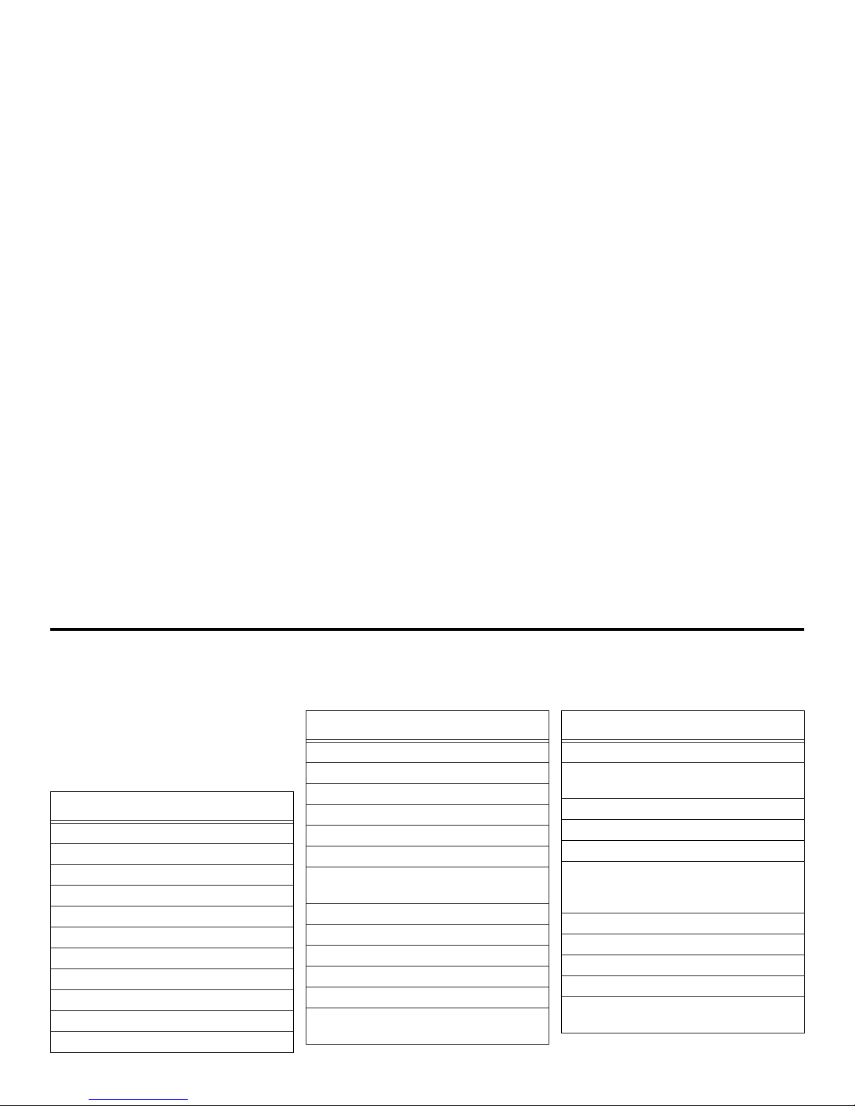
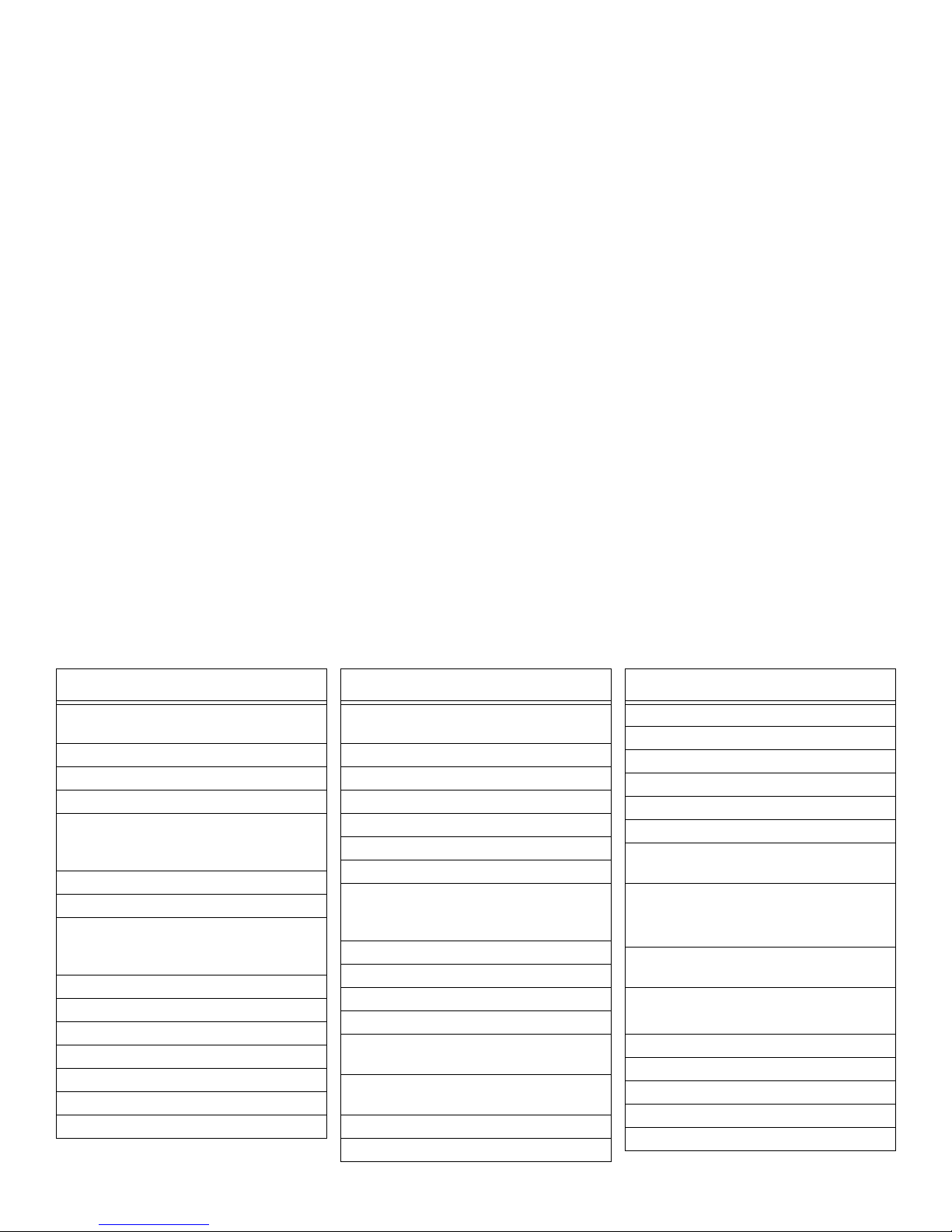
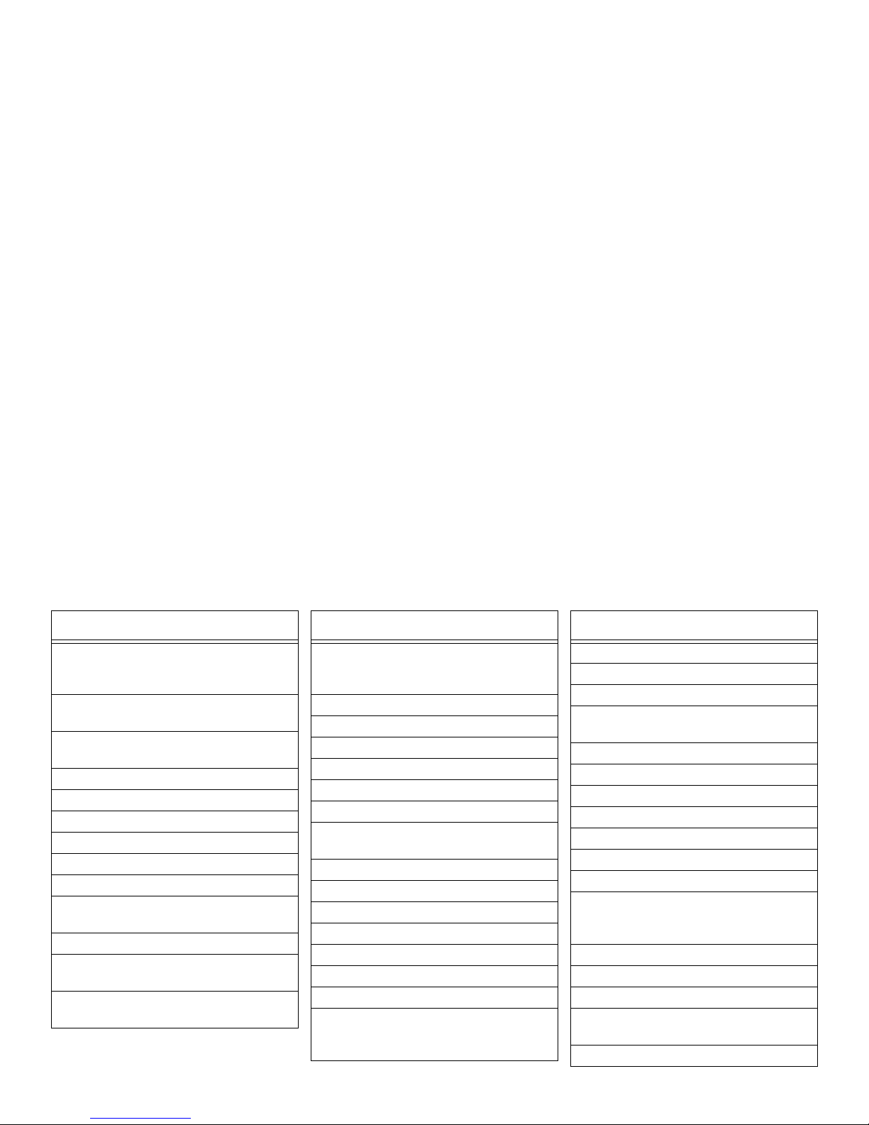
TV AND VCR CODES
TV CODES
This section lists TV models that are
compatible with the RG2100 and their
codes. If you do not find the TV code
you need in the list, call your NSP.
TV and Codes
AOC: 005, 006, 019, 120, 140
Admiral: 018, 194, 210
Aiwa: 194, 251
Akai: 000, 005, 032, 070
Amark: 120, 224
Amstrad: 033
Anam: 005, 009, 021, 041, 120, 121
Anam-National: 211
Archer: 120
Audio Dynamics: 238
Audiovox: 120
Bell & Howell: 018
Broksonic: 005, 174, 225, 226
CXC: 041
Candle: 005, 006, 022, 025
Capehart: 019
Centurion: 194
Citizen: 005, 006, 016, 018, 022, 024,
025, 098, 202, 224
Concerto: 005
Contec: 017, 041, 185, 227
Corando: 224
Craig: 021, 041
Crown: 098
Curtis-Mathes:005, 006, 016, 018, 059,
098, 125, 194, 202, 210, 224, 231
TV and Codes
DBX: 238
Daewoo: 005, 024, 029, 030, 032, 098,
214, 215, 224, 247, 252
Daytron: 098, 194, 224
Dimensia: 125
Electrohome: 098, 224, 240
Emerson: 005, 017, 033, 035, 037, 038,
039, 041, 098, 143, 176, 185, 187, 203,
222, 223, 224, 225, 226, 227, 251
Fisher: 042, 194, 217
Fujitsu: 187
Funai: 041, 187, 251
Futuretech: 041
GE: 003, 005, 008, 009, 043, 125, 130,
147, 206, 210, 211, 228, 231, 248
TV and Codes
Page 78
78
Goldstar: 005, 010, 045, 098, 194, 223,
224, 230, 238
Hallmark: 005
Harmon Kardon: 238
Hinari: 187
Hitachi: 005, 018, 048, 049, 050, 051,
052, 053, 054, 055, 098, 126, 185, 224,
231, 251
Infinity: 010
JBL: 010
JC Penney: 003, 005, 006, 014, 016,
043, 096, 098, 125, 194, 206, 210, 223,
224, 231, 238, 242
JVC: 057, 059, 060, 235, 238
Jensen: 056
KMC: 224
KTV: 005, 039, 041, 098, 224
Kawasho: 061
Kenwood: 006, 235, 251
Kloss: 022, 110
TV and Codes
LXI: 003, 005, 010, 125, 129, 131, 194,
223, 251
Lloytron: 224
Lodgenet: 018
Logik: 018
Luxman: 005
MGA: 005, 006, 071, 072, 187, 194, 240
MTC: 005, 006, 016, 202
Magnavox: 000, 005, 006, 010, 017,
025, 027, 067, 068, 110, 154, 167, 175,
194, 224, 231, 237, 251, 255
Majestic: 018
Marantz: 005, 006, 010, 068, 237, 238
Marta: 223
Matsui: 032, 109
Memorex: 018, 032, 194, 223, 242, 244,
248, 251
Mitsubishi: 005 , 017, 070, 071, 072, 123,
149, 187, 194, 239, 240
NAD: 002, 131
NEC: 005, 006, 007, 191, 194
TV and Codes
National: 008, 010, 011, 012, 190, 211
Onwa: 041
Optimus: 242
Optonica: 129
Orion: 225, 226
Osume: 017
Panasonic: 008, 009 , 010, 01 1, 012, 17 7,
211, 231, 242
Philco: 005, 006, 010, 025, 067, 068,
110, 224, 237, 251
Philips: 005, 010, 025, 027, 068, 220,
223, 224, 237, 251
Pioneer: 002, 048, 051, 076, 235
Portland: 005, 098, 224
Proscan: 125, 147, 210
Proton: 005, 006, 013, 019, 098, 224
Pulsar: 001, 248
Quasar: 008, 009, 211, 231, 242
TV and Codes
Page 79
79
RCA: 003, 005, 014, 048 , 078, 07 9, 080,
082, 084, 085, 086, 087, 125, 147, 210,
231, 251, 255
Radio Shack: 005, 041, 098, 141, 194,
224, 230, 242
Realistic: 041, 141, 194, 222, 223, 224,
251
Runco: 243
SAA: 145
SSS: 005, 041
Saba: 051
Saisho: 032, 033, 109
Sampo: 006, 019, 194
Samsung: 005, 006, 010, 016, 032, 098,
194, 202, 221, 224, 244, 246, 247
Sansui: 225, 235
Sanyo: 017, 042, 089, 092, 109, 194,
217, 244
Scott: 005, 037, 041, 093, 098, 187 , 194,
224, 247
TV and Codes
Sears: 003, 005, 042, 096, 098, 099,
101, 102, 104, 125, 131, 187, 194, 202,
217, 223, 224
Sharp: 017, 098, 129, 141, 2 00, 224 , 255
Signature: 018, 251
Sony: 000, 017, 109, 180
Soundesign: 005, 025, 041, 251
Spectricon: 120
Supra: 005, 022
Sylvania: 005, 006, 010, 025, 068, 098,
110, 194, 224, 237, 240, 251
Symphonic: 32, 251
TMK: 005
Tandy: 098, 113, 129, 251
Tatung: 009, 211
Teac: 251
Technics: 008, 242
Techwood: 005
Teknika: 005, 010, 016, 018, 022, 024,
025, 041, 072, 098, 114, 187, 202, 223,
224, 251
TV and Codes
Telerent: 018, 224
Teletech: 032
Thomson: 051
Toshiba: 016, 017, 096, 131, 194, 202,
240, 247
Totevision: 098, 223, 224
Universal: 043, 206
Vector Research: 006, 238
Victor: 057, 235
Video Concepts: 070, 238, 251
Vidtech: 005
Viking: 022
Wards: 000, 005, 006, 010, 018, 043,
067, 068, 125, 141, 187, 194, 206, 224,
251
Westinghouse: 194
Yamaha: 005, 006, 238, 251
Yorx: 194
Zenith: 001, 018, 223, 225, 235, 248,
249, 251
Zonda: 120
TV and Codes
Page 80
80
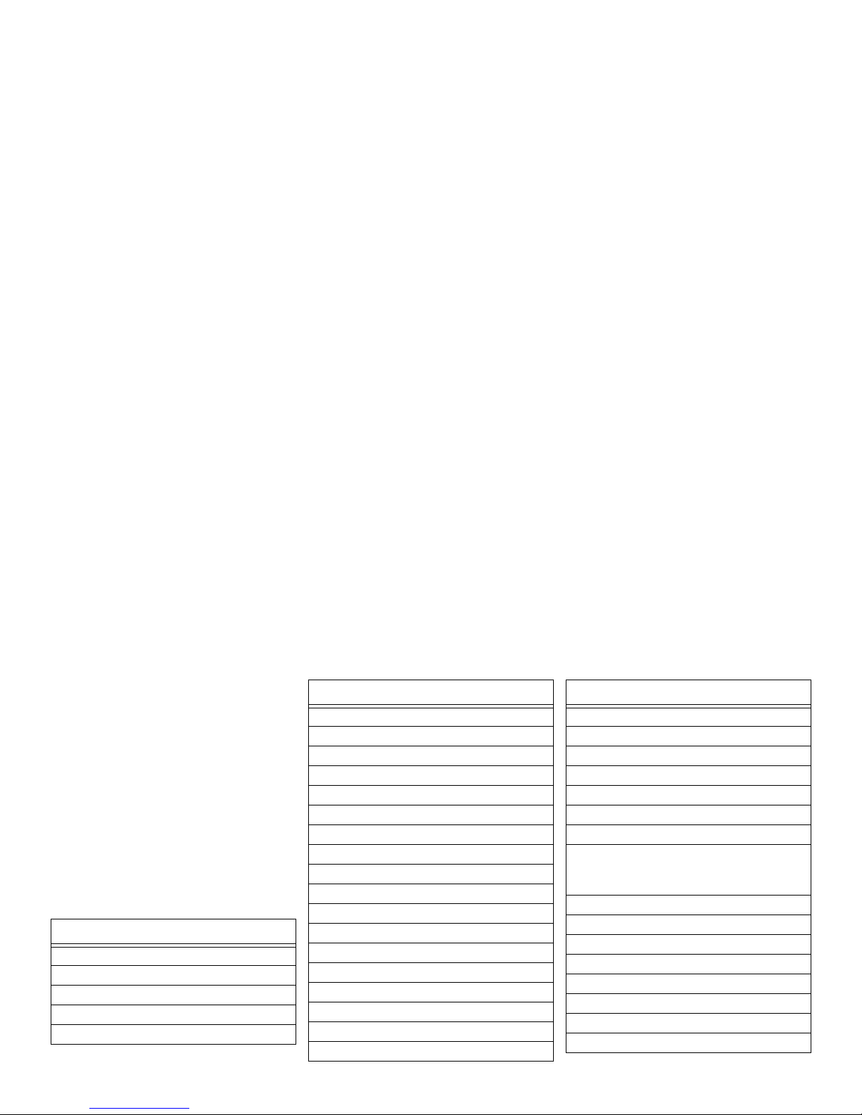
VCR CODES
This table lists the VCR models and
code numbers that are compatible with
the RG2100. If you do not find the code
you need in the list shown, call your
NSP.
Note: The N
3
Residential Gateway IR
transmitter feature is not compatible
with the following equipment:
• Samsun VCR/TV model number
CDX1342
• Philips VCR model number
VRX364AT
VCR and Codes
Admiral: 048, 209
Adventura: 000
Aiko: 278
Aiwa: 307, 000, 037
Akai: 106, 053, 041, 061
America Action: 278
American High: 035
Asha: 240
Audiovox: 037
Beaumark: 240
Bell & Howell: 104
Broksonic: 121, 184, 002, 209, 211, 479
CCE: 072, 278
Calix: 037
Canon: 035
Capehart: 020
Carver: 081
Cineral: 278
Citizen: 278, 037
Colt: 072
Craig: 037, 072, 047, 240, 271
Curtis Mathes: 035, 041, 060, 162
Cybernex: 051, 240
VCR and Codes
Daewoo: 278, 561, 020, 045
Daytron: 020
Denon: 042
Dynatech: 000
Electrohome: 037
Electrophonic: 037
Emerex: 03 2
Emerson: 184, 002, 209, 278, 036, 121,
211, 208, 479, 561, 061, 088, 212, 000,
037, 043, 068
Fisher: 047, 104, 054, 066
Fuji: 033, 035
Funai: 000
GE: 035, 060, 048, 202, 240
Garrard: 000
Go Video: 432, 526, 232
GoldStar: 037, 038
Gradiente: 008, 000
VCR and Codes
Page 81
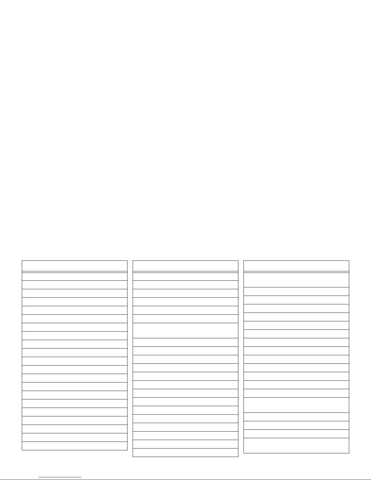
81
Grundig: 195
Harley Davi dson: 000
Harman/Kardon: 038, 081
Harwood: 0 68, 072
Headquarter: 046
Hitachi: 042, 105, 000, 041
HI-Q: 047
Hughes Network Systems: 042
JVC: 067, 008, 041
Jensen: 041
KEC: 037, 278
KLH: 072
Kenwood: 041, 067, 038
Kodak: 035, 037
LXI: 037
Lloyd's 000, 208
Logik: 072
MEI: 035
MGA: 043, 061, 240
MGN T echnology: 240
MTC: 000, 240
VCR and Codes
Magnasonic: 278
Magnavox: 035, 081, 000, 039, 149
Magnin: 240
Marantz: 081, 035
Marta: 037
Matsushita: 035, 162
Memorex: 104, 047, 000, 037, 048, 035,
046, 240, 307, 039, 209, 162
Minolta: 105, 042
Mitsubishi: 043, 173, 061, 048, 067
Motorola: 035, 048
Multitech: 000, 072
NAD: 058
NEC: 038, 040, 041, 067, 104
Nikko: 037
Nikon: 034
Noblex: 24 0
Olympus: 035
Optimus: 162, 048, 058, 037, 104, 432
Optonica: 062
Orion: 479, 002, 184, 209
Panasonic: 035, 162, 077, 225, 616
VCR and Codes
Penney: 035, 240, 037, 042, 038, 040,
054
Pentax: 042, 105
Philco: 035, 209, 479
Philips: 081, 035, 062
Pilot: 037
Pioneer: 058, 067
Portland: 020
Profitronic: 240
Proscan: 060, 202
Protec: 072
Pulsar: 039, 051
Quarter: 046
Quartz: 046
Quasar: 035, 162, 077
RCA: 060, 149, 202, 042, 105, 035, 048,
077, 106, 240
Radio Shack: 000
Radix: 037
Randex: 037
Realistic: 000, 104, 047, 048, 037, 035,
062, 046, 066
VCR and Codes
Page 82
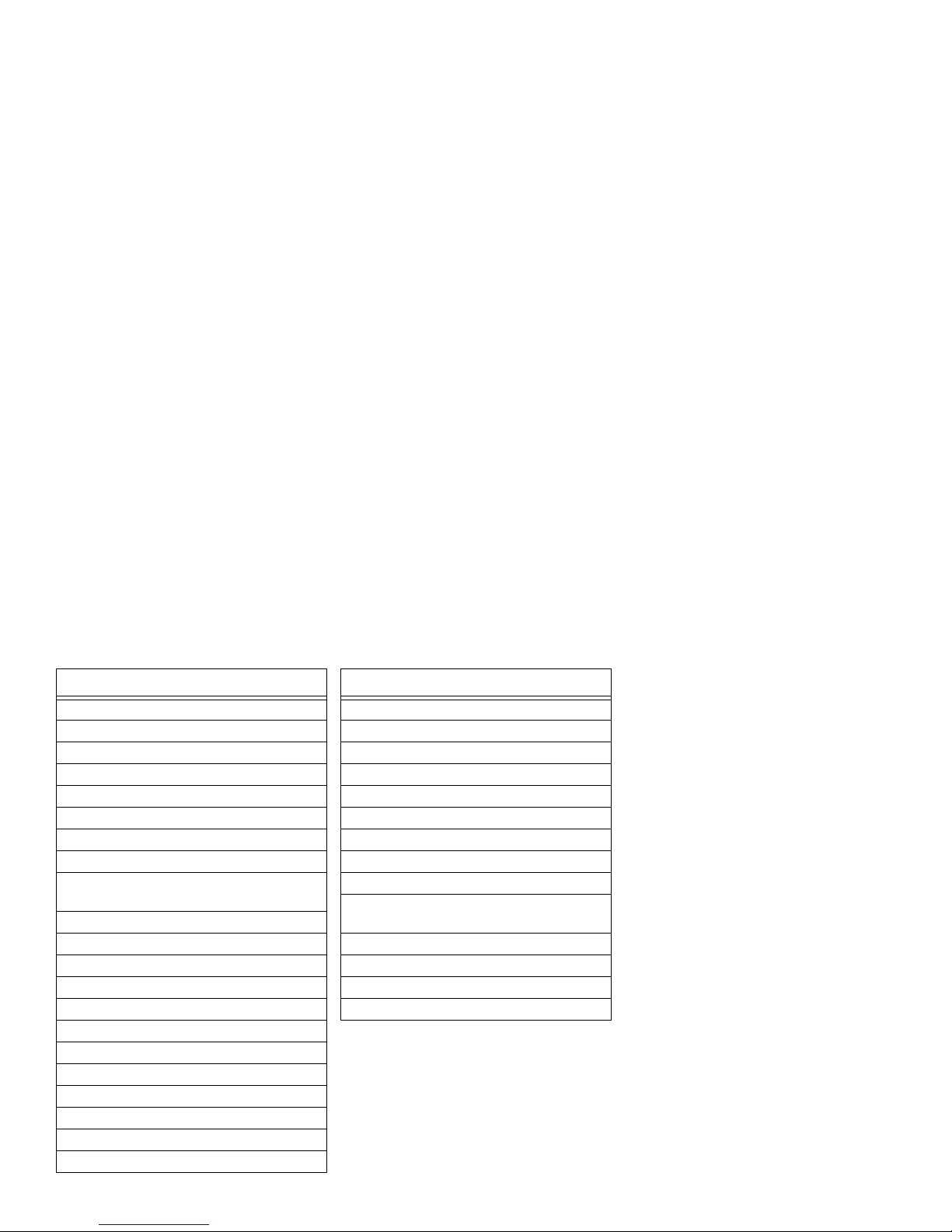
82
Ricoh: 034
Runco: 039
STS: 042
Samsung: 045, 051, 053, 240
Sanky: 039, 048
Sansui: 041, 479, 000, 067, 209, 271
Sanyo: 047, 046, 104, 240
Scott: 184, 211, 121, 043, 045, 210, 212
Sears: 054, 105, 037, 042, 000, 035, 046,
047, 066, 104
Semp: 045
Sharp: 048, 062
Shintom: 072
Shogun: 051, 240
Singer: 072
Sony: 033, 034, 032, 000, 035
Sylvania: 035, 081, 000, 043
Symphonic: 000
TMK: 036, 208, 240
Tatung: 041
Teac: 000, 041
Technics: 035, 162
VCR and Codes
Teknika: 000, 035, 037
Thomas: 000
Toshiba: 045, 210, 212, 043, 066, 366
Totevision: 037, 240
Unitech: 240
Vector: 045
Vector Research: 038, 040
Video Concepts: 040, 045, 061
Videosonic: 240
Wards: 035, 06 0, 062, 000, 047, 212 , 240,
042, 048, 072, 081, 149
White Westinghouse: 278, 209
XR-1000: 072, 000, 035
Yamaha: 038
Zenith: 039, 000, 033, 034, 209, 479
VCR and Codes
Page 83
83
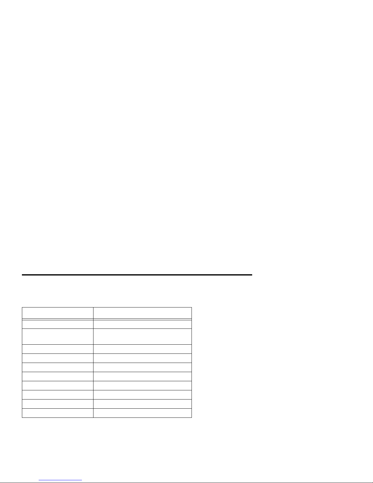
SPECIFICATIONS
Cabling Requirements
Input/Output Cable (connector)
NETWORK IN CA T 5 (RJ-45)
DOLBY DIGITAL
AUDIO(AC-3)
shielded phono cable (RCA male)
AUDIO L/R shielded phono cable (RCA male)
VIDEO shielded phono cable (RCA male)
S-VIDEO S-video
NETWORK IN/TV OUT coax (F male)
TV OUT coax (F male)
ETHERNET CAT 5 cable (RJ-45)
HPNA (future) telephone cable (RJ-11)
IR BLASTER n/a (3.5 mm mini male)
Page 84
84
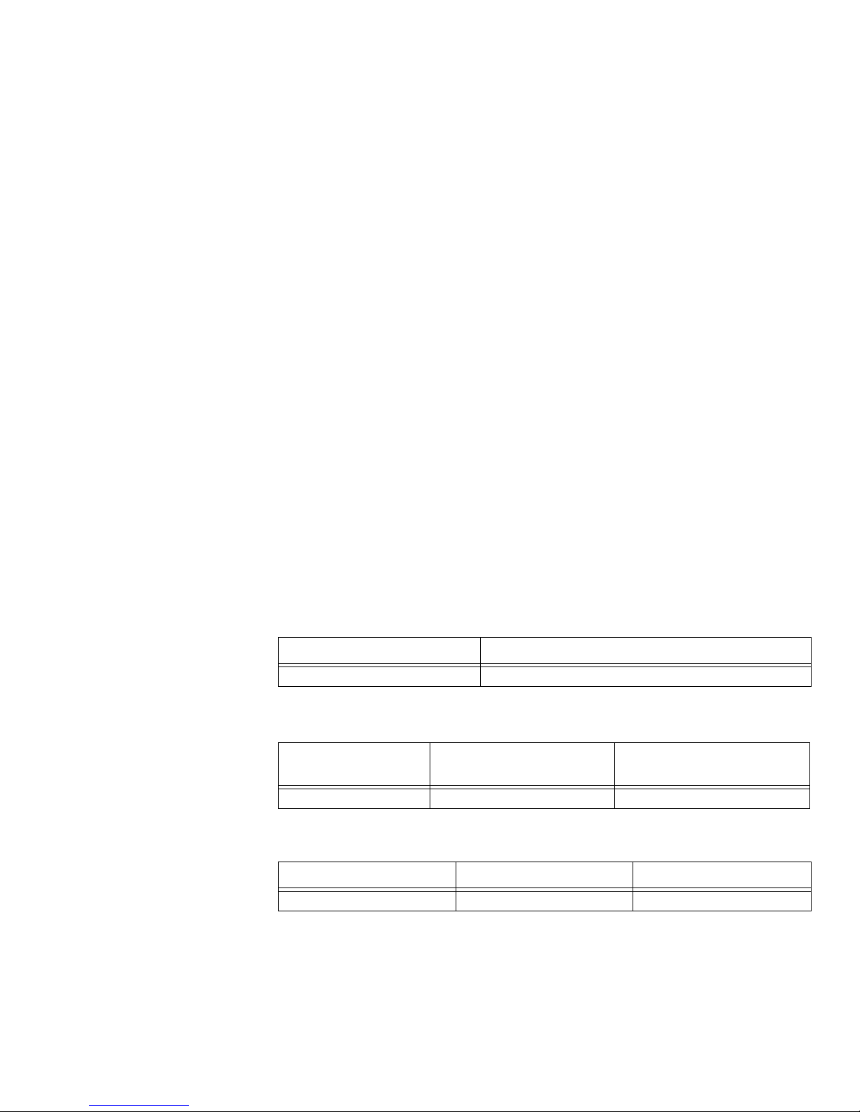
Power Requirements
Environmental
Dimensions
CERTIFICATIONS
• GR-1089-CORE
• FCC Title 47 Part 15, Class B
• UL 1950
• UL and CSA 1950, and CE
• ASTM D (mechanical shock and vibration standards)
Condition Power Consumption (watts)
normal oper ation <30 watts, 100-240VAC 50-60Hz
Temperature Range Storage Range
Humidity Range
(non-condensing)
0 to 45°C -40°C to + 80°C 5% to 95%
Height Widths Depth
2 5/8 in. (6.67cm) 15 5/8 in. (39.7cm) 11 3/8 in. (28.9cm)
Page 85

85
FCC S
TATEMENT OF COMPLIANCE
This device complies with Part 15 of the FCC Rules. Operation is subject to the following two conditions: (1) this device may not cause harmful interference, and (2) this
device must accept any interference received, including interference that may cause
undesired operation.
N
OTICE This equipment has been tested and found to comply with the limits for a
Class B digital device, pursuant to Part 15 of the FCC Rules. These limits are
designed to provide reasonable protection against harmful interference in a residential
installation. This equipment generates, uses and can radiate radio frequency energy
and, if not installed and used in accordance with the instruction manual, may cause
harmful interference to radio communications. However, there is no guarantee that
interference will not occur in a particular installation. If this equipment does cause
harmful interference to radio or television reception, which can be determined by turning the equipment off and on, the user is encouraged to try to correct the interference
by one or more of the following measures:
• Reorient or relocate the antenna.
• Reorient or relocate the receiving antenna.
• Increase the separation between the equipment and receiver.
• Connect the equipment into an outlet on a circuit different from that to which the
receiver is connected.
• Consult the dealer or an experienced radio/TV technician for help.
Page 86

86
Page 87

INDEX
A
about this manual 10
Advanced Use 33
B
batteries
remote control
32
buttons
remote control
20
RG2200 16
RG2200, front panel 17
C
cable requirements 83
Certifications 84
changing channels 21
using the remote control 21
using the RG2200 buttons 21
channel list
select
22
channel order
favorite
22
setting up 22
closed captioning 50
codes
TV
77–79
VCR 80–82
Controlling TV Volume 21
D
dimensions 84
Display Language 49
changing 49
down arrow, about 17
E
Emergency Alert Device Support 51–54
entertainment center 69
advanced, illustrated 69
basic, illustrated 68
Ethernet connections 55
single PC 56
F
FCC statement of compliance 85
front panel
Page 88

buttons 17
G
Gateway ID 38
determining 34–37
setting 38
Gateway Menu, illustrated 35, 45
Getting Started 15
I
IDs
Gateway, determining
34–37
Important Safeguards 5
Internet
connecting multiple PCs
57
Internet connections
PCs, multiple
56
Introduction 9
IR, about 19
L
language alternatives 48–49
M
message waiting 24
mute TV volume 22
N
Network Access Provider
finding
76
Network Service Provider
Services
11
P
Parental Control 27
parental locks 27
pay-per-view
using
27
plugging in devices 59
power requirements 84
preface 5
R
recording your favorite programs 29
remote control 19
buttons 20
buttons, described 20
using 19
remote control ID
setting
40–41
remote control ID form 13
Remote Control ID menu, illustrated 37
remote control ID, determining 39
Remote Control Setup menu, illustrated 36
Page 89

replacing remote control batteries 32
RF settings 48
RF settings, verifying 46–48
RG2200
using
16
RG2200 buttons, illustrated 16
RG2200 front panel
Exit button, about
17
Message LED, about 18
Online LED, about 18
Record LED, about 18
Select button, about 17
Setup button, about 17
Status LED, about 18
Up arrow, about 17
S
Safety 8
advisories and labels 8
repairs 8
secondary audio 48
settings
changing
33
programming 33
Setup Menu, illustrated 47
Setup TV menu 44, 46
Specifications 83
SRC-200 remote control
TV codes, list
??–79
Surround Sound, wiring illustrated 69
T
Teletext 51
temperature
operating range
84
troubleshooting 71–75
blue or black screen 73
no picture 72
no power 74
no sound 72
picture distortion 73
remote control won’t change channels 71
replacing remote control batteries 32
snowy picture 73
VCR will not play tapes 74
VCR will not record 74
TV codes 77
obtaining, using the code search method 43
programming 42
SRC-200, list 77–79
verifying 43
TV codes, list 77–79
TV Setup Menu, illustrated 46
TV volume
controlling
21
TV/VCR/Audio Connections 61–69
Page 90

TVs
closed captioning
50
programming 44–46
U
UHF, about 19
unmute TV volume 22
unplugging devices 59
V
VCR codes 80–82
programming 31
VCR, plugging into 59
VCR, using the RG2200 to start 29
VHF channels, about 12
video recording 29
W
wiring
advanced home entertainment center with Surround
Sound
69
basic home entertainment center 68
composite video with AUDIO-L/AUDIO-R and TV1 65
S-VIDEO and AUDIO-L/AUDIO-R to audio receiver and
TV1
66
S-VIDEO/AUDIO-L/AUDIO-R to TV1 63
TV OUT to TV1 61
TV OUT to VCR/TV1 64
VIDEO/AUDIO-L/AUDIO-R to TV1 62
 Loading...