

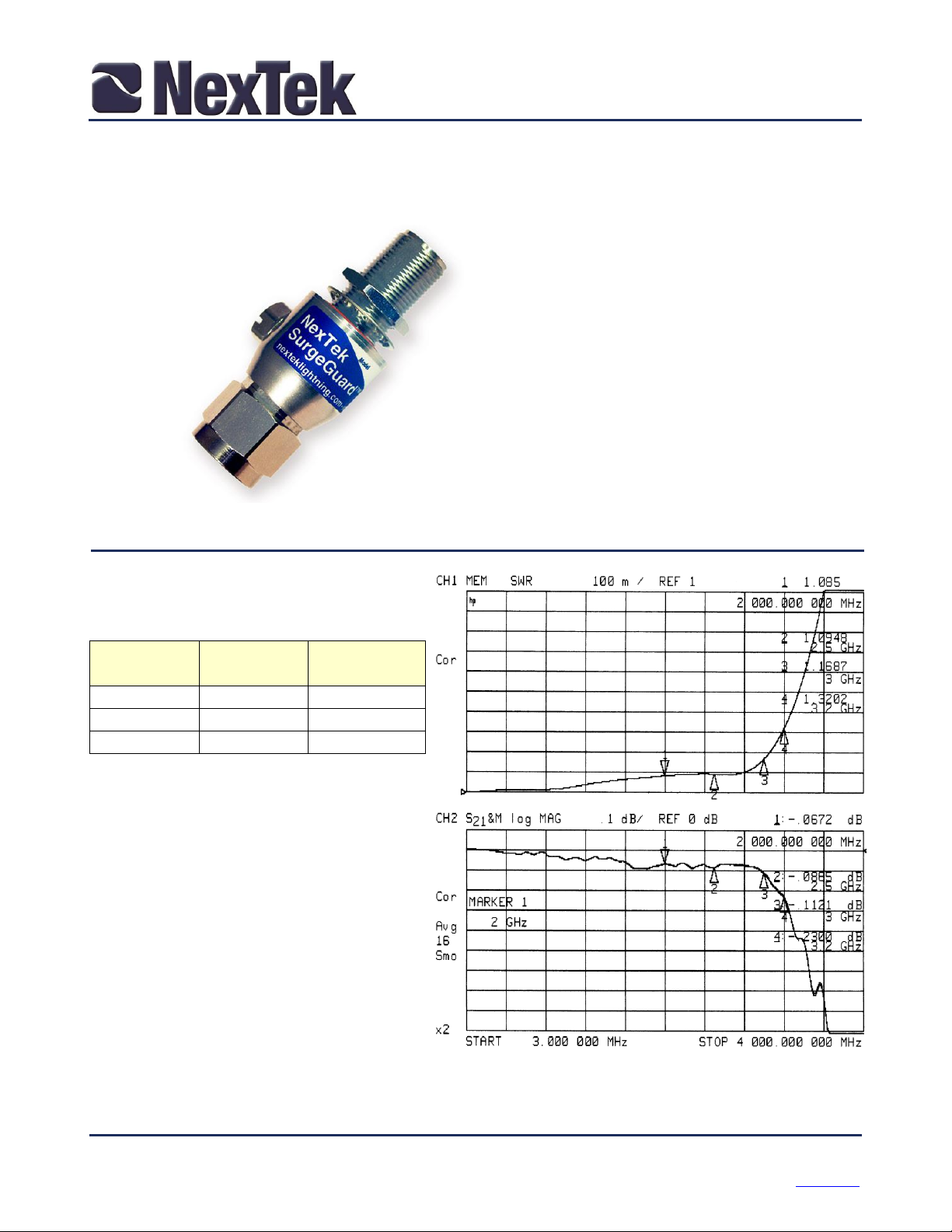
Product Specification
Frequency
(GHz)
VSWR
Insertion
Loss (dB)
dc – 2.5
1.15 Max
0.10 Max
2.5 – 3.0
1.20 Max
0.15 Max
3.0 – 3.2
1.35 Typ
0.25 Typ
Typical VSWR and Insertion Loss
PTRONxONFxxS
Gas Discharge Tube Lightning Arrestor
N Connectors and a Replaceable Protective Element
Features:
Frequency to 3.2 GHz Excellent
RF Performance
Multiple Strike Capability
50 kA Surge Protection
Bi-directional Protection
Rugged and Waterproof
High RF Power and Low PIM
PTRONMONFxxS (N-Male to N-Female)
RF Specifications
Nominal Impedance – 50
Through Current: 65V/10A Max
RF Power: See Protection Voltage table
PIM3: -116 dBc
(2X43 dBm 1.9 GHz tones)
Transient Specifications
(1.2X50s Voltage / 8X20s Current waveform)
Maximum Transient: 50 kA
Multiple Strike: 20 kA 10 times
Let-through: See Protection Voltage table
Replaceable Gas Discharge
Tube 90V to 1000V
©NexTek, Inc. This specification is for reference only, and is subject to change without notice Page 1 of 2
2 Park Drive, Building #1 (978) 486-0582
Westford, MA 01886 nextek.com

Temperature Range
-40oC to +90oC
Salt Fog
MIL-STD-202 Method 101D / Condition B (35oC/96 hrs)
Immersion
MIL-STD-202 Method 104A / Condition A (65oC to 25oC w/NaCl – 2
Moisture Resistance
MIL-STD-202 Method 106E (65 oC/98% RH condensing/240 hrs)
Temperature Shock
MIL-STD-202 Method 107D / Condition B-1 (25 cycles -65oC to +125oC)
Life (Elevated Temperature)
MIL-STD-202 Method 108A / Condition A (96 hours at 100oC)
Dust and Waterproof Rating
IEC529 IP68 (dust-tight and water proof 24 hrs / 1 m)
Vibration
MIL-STD-202 Method 204D / Condition D (10Hz-2kHz 0.06”DA/20g)
Mechanical Shock
MIL-STD-202 Method 213 / Condition A (50g/11ms ~24”)
Component
Material
Finish
Outer Parts
Brass
Guardplate™
Center Contact
BeCu
Gold
Insulator
PTFE
-
Gasket
Si Rubber
-
Protection
Voltage
Voltage
Code1
RF Power
(W)2
Let-through
(Vpk / mJ)3
90
09
37
600 / 0.3
150
15
95
600 / 0.3
230
23
240
650 / 0.5
350
35
550
800 / 0.7
470
47
1000
1200 / 2.2
600
60
1600
1500 / 4.4
800
80
2900
1900 / 9.0
1000
99
4500
2200 / 14
Part Number
PTR ONXONF XX S
“S” Specifies the Standard model,
mounting dimensions shown above
Voltage Code - select based on the RF power. Use
23 for most applications
Connector Codes – ONF ONF for female to female,
ONM ONF for male to female
PTR Family - (Protector w/ replaceable Gas
Discharge Tubes)
Mechanical Specifications
Weight 0.28 pounds typ/125 g typ
Environmental Specifications
Product Specification
PTRONxONFxxS
Material and Finish
Guardplate™ is an alloy finish with the PIM and conductivity
of Silver and the durability and anti-tarnish properties of
Nickel.
1
Use the voltage code in the part number
2
For multiple carriers, sum of peak voltages
should not exceed 60% of the protection voltage
3
Input is 6kV @ 1.2x50s/ 3kA @ 8x20s.
Protection Voltage
2/12/16 This specification is for reference only, and is subject to change without notice Page 2 of 2
 Loading...