

Page 1
2W UHF
Transceiver
DC1110
User Manual
Use of the citizen band radio service is licensed in Australia by
ACMA Radiocommunications (Citizen Band Radio Stations)
Class Licence and in New Zealand by MED General User Radio
Licence for Citizens Band Radio. Operation is subject to
conditions contained in those licences.
i
Page 2

INSTRUCTIONS BEFORE USE
Do not use a transceiver with damaged antenna, because it might cause slight burns once
skin contact carelessly.
Do not use transceiver or battery charging, when they are under explosive environment (such
as gas, dust and smoke etc.).
When parking at gas station,or being refueling, please turn off the transceiver.
There are not any reason to modify or adjust the transceiver.
Do not keep your transceiver by prolonged direct sunlight, as well can not place it near heater
machine .
Do not place the transceiver on where are filled with most dust, damp and water splashing, as
well as do not put it on the not unstable surface.
Repair work only do by the professional technician.
If it appears that the transceiver diffuses peculiar smell or smoke, please turn off it immediate-
ly, and take down battery pack from radio body, then contact with supplier .
Safety:
It is very important for the user to know and recognize the general danger of using the radio.
ii iii
MAIN FEATURES
80 memory channels
CTCSS/DCS Function;
Single call /group call/all call, Remote kill, stun, Activate & Revive
2-tone
FM radio (87-108Mhz)
Emergency Alarm
ANI and DTMF Function
Humanization phone book function
Powerful programmable keypad function
VOX function
Voice prompt
English
Page 3

TRANSMIT CTCSS AND DCS
CONTENT
PREPARATION .................................. 01
ACCESSORIES ....................................... 01
CHARGING INSTRUCTION .................... 01
CHARGE STEPS ..................................... 02
INSTALL/REMOVE BATTERY PACK .......02
INSTALL ANTENNA ................................03
INSTALL BELT CLIP ................................ 04
INSTALLING THE OPTIONAL SPEAKER/
MICROPHONE ........................................ 04
GETTING STARTED ..........................05
DESCRIPTION OF TRANSCEIVER ......... 05
LCD DISPLAY ......................................... 06
BASIC OPERATION .......................... 07
SHORTCUT OPERATION........................ 07
iv v
MENU SHORTCUT SETTING ........... 09
FUNCTION OPERATION AND
INSTRUCTION ................................... 10
BEEP PROMPT (BEEP) ........................... 10
SQUELCH LEVEL SETTING (SQL) ......... 10
TX POWER SETTING .............................. 11
VOX FUNCTION SETTING (VOX.SWI) .... 11
POWER-ON DISPLAY (OPN.MSG) ......... 12
REVERSE FREQUENCY SETTING
(REV T-R) ................................................. 13
FREQUENCY STEP SETTING (STEP)..... 13
OFFSET FREQUENCY SETTING
(OFFSET) ................................................. 14
DIRECTION OF OFFSET FREQUENCY
SETTING (SFT-D) .................................... 14
RECEIVE CTCSS AND DCS
(R-CTDC) ................................................ 15
(T-CTDC) ................................................. 16
KEYPAD LOCK (LOC.KEY) ..................... 17
VOICE PROMPT (VOICE) ........................ 17
CHANNELS DISPLAY MODE
(MDF-CH) ................................................ 18
SIGNALING OPTIONAL (SIG.OPT) ......... 18
PTT-ID TRANSMITTING (PTT-ID) ............ 19
SCAN ADD AND DELETE (SC.ADD) ....... 19
SCAN START (SCAN).............................. 20
OFFSET SETTING (OFFSET) ..................21
OTHER FUNCTION INSTRUCTION . 23
MANUAL LOCK KEYBOARD .................. 23
FM RADIO (FM) ....................................... 23
FLASHLIGHT ..........................................23
MONITOR FUNCTION (MON) ................. 24
WIRE CLONE (COPING) ......................... 24
CHANNEL/FREQUENCY MODE
(VFO/MR) ................................................24
APPENDIX ......................................... 25
CTCSS Chart .......................................... 25
DCS Chart ............................................... 26
Page 4
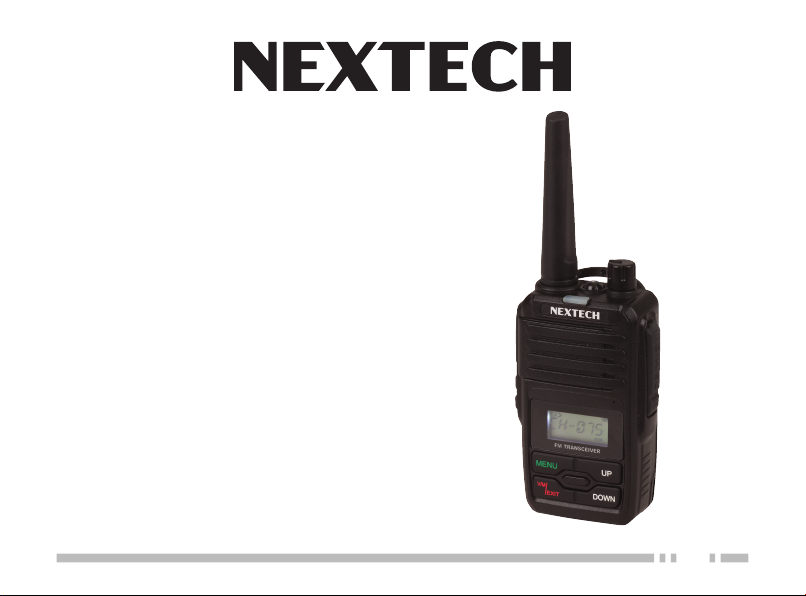
charging. Charging fully then the charger
green light flashing, charging end.
PREPARATION
pack is about 13 hours. The average use
time is 5% receive time, 5% transmit time,
and 90% standby time.
▶ACCESSORIES
Carefully take out the transceiver from the
box. We recommend that confirm the below
goods before get rid of the packing.
Supplied Accessories
Item Qty.
Radio 1
Antenna 1
Li-ion Battery pack 3.7V 1
Charger /Adapter 1
Belt Clip 1
User Manual 1
Hang Strap 1
▶CHARGING INSTRUCTION
The note of Li-ion battery charging below:
yThe battery pack had not charging when
01 02
come out the factory, please charging
first when you want to use. After the purchase or long-term storage (more than two
months), the first to charging the battery
pack can not make the battery pack up to
its saturation use of capacity. In repeated
charging and discharging two, three times,
The effect can be achieved the normal
charging and battery power.
yBefore charging, should turn off the trans-
ceiver power. if use the transceiver while
it’s battery charging, it would badly influence on the battery normally charging.
y The Battery under the normal charging
many times, The time of using time is not
adding anymore, it mean that life of battery
is close to over, should replace new one;
yAs calculated, The average time of battery
CAUTION
⚠
Do not charging the battery pack again, when
it’s already fully charging before. otherwise it
would cause the life of battery pack to shorten, even it may be damaged.
When it’s charging fully, please remove it away
charger cup.
Do not short the battery terminal or dispose of
the battery by fire.
▶CHARGE STEPS
The charger plug into the mains of 220V
power outlet,the charger indicator green light
flashing.
The battery pack or the transceiver with battery pack insert into the charger card slot. (as
picture show).
The charger red light flashing to start
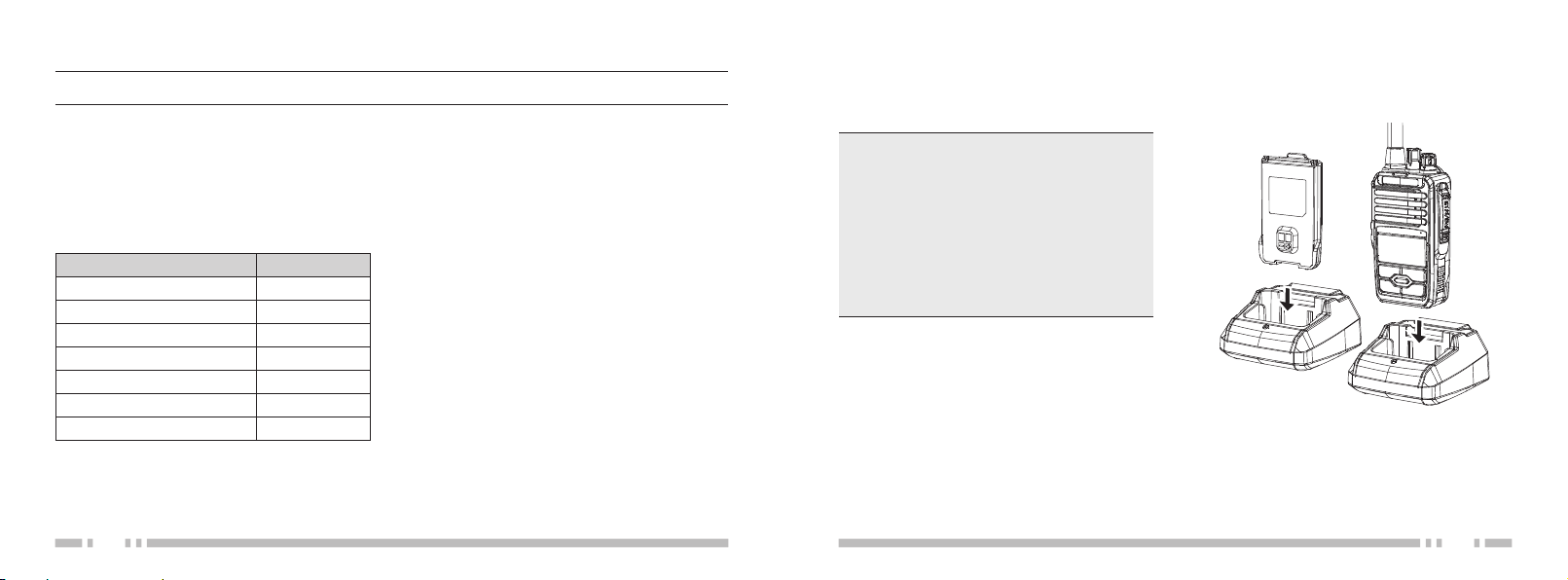
▶INSTALL/REMOVE BATTERY PACK
When install the battery pack, should match
the corresponding location of aluminum
frame of transceiver backside, then push into
Page 5
the battery towards direction.The Buckles on
qwe
the tail of battery would fasten the battery
pack, until can hear “clicking” sound;
To remove the battery pack, please turn off
the transceiver first. Then press the buckles
of the battery, at the same time, the battery
will be pushed back, take the battery away;
03 04
▶INSTALL ANTENNA
Install the antenna into the transceiver connector, holding the antenna base and turning
it clockwise until secure;
NOTE
⚠
Please do not antenna as a handle. the keys or
external type loudspeaker microphone hanging
on the antenna, which can damage the antenna
and lowered transceiver’s performance.
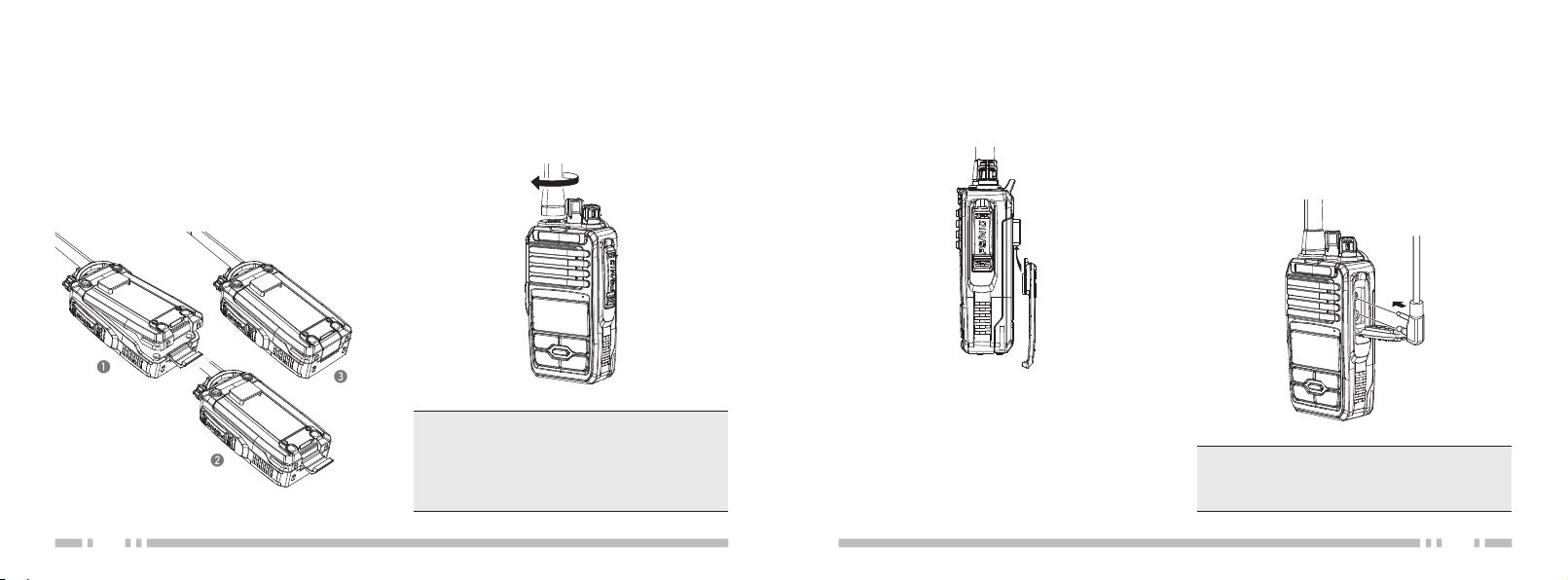
▶INSTALL BELT CLIP
Belt clip insert into back of battery hole.
▶INSTALLING THE OPTIONAL
SPEAKER/MICROPHONE
Outward apart the moistureproof rubber of
the headphone mouth, Insert the speaker/microphone plugs into the speaker/microphone
jacks.
NOTE
⚠
The transceiver is not fully water resistant while
using the speaker/microphone.
Page 6

GETTING STARTED
PTT Button
FM Radio/
MONI Key
(Side Key 1
Flashlight/
Alarm Key
(Side Key 2
Li-ion Battery
▶DESCRIPTION OF TRANSCEIVER
)
)
Antenna
Speaker
LCD
Display
Function
Keypad
LED Flashlight
Power/Volume
Knob
LED
Indicator
Microphone
Speaker/
MIC Jack
Pack
▶LCD DISPLAY
There are various indicate marks displaying on the screen. please refer the below table to learn
what the indicate marks:
CTCSS
DCS
VOX Function
Narrow Band Function
Battery Capacity display
FM NAR LOW VOX SCN
75
50
25
Channel No.
Frequency working/Menu setting
Keypad Lock
Frequency Mantissa indicate
Low Power setting,
Scan Function
05 06
Page 7

yTurn clockwise would turn up the volume
BASIC OPERATION
▶SHORTCUT OPERATION
PTT
yPush [PTT] and speak to microphone to
transmitting, Release [PTT] when you finish speaking to receiving;
Side key 1 (FM/MONI)
yShort press [Side key 1] would turn on
Monitor Function, Then Short press again,
would turn off it;
yLong press [Side key 1] would turn on FM
radio Function, Then Long press again,
would turn off it;
Side key 2 (Flashlight/Alarm)
yShort press [Side key 2] would turn on the
Flashlight, Then Short press again, would
07 08
turn off it;
yLong press [Side key 2] would turn on the
Alarm, Then Long press again, would turn
off it;
Function Keypad
y[MENU]: Short press [MENU], go ahead
Menu operation, when operate Menu function, press this key can to menu list and
confirm the menu item adjustment;
y[UP] / [DOWN]: Function selection in the
menu and Frequency Setting;
y[V/M | EXIT]: Press this key to Exit;
Power Switch/Volume Control
yTurn it clockwise to switch on transceiver;
Turn it counterclockwise until a “clicking”
sound, that switch off transceiver;
level, turn counterclockwise turn down the
volume level;
LED Indicator
yRed light flashing when transmitting;
yLight light flashing when receiving;
Speaker/Microphone Jack Connector
yUsed for Earpieces Insert;
yUsed for programming cable connection,
can programming the frequency via PC
software and Software updating;
Page 8

MENU SHORTCUT SETTING
FUNCTION OPERATION AND INSTRUCTION
1. Press the [MENU]: go ahead main menu function operation;
2. Press the [MENU]: go ahead Sub menu function operation;
3. Press the [UP] or [DOWN]: adjust every menu functions settings;
4. Press the [MENU] to confirm; Press [V/M | EXIT] to exit;
▶BEEP PROMPT (BEEP)
It is setting function of keys operation sound,
when you operation keys would appear “DU”
sound.
Operation step below:
NOTE
⚠
Under the mode of MR (Frequency Mode), The menu setting is not effect including: CTCSS/DCS Setting;
Wide/Narrow Band Setting, PTT-ID Setting;
1. Under the mode
of VFO (Frequency
Mode) or MR (Chan-
SCN
nel Mode), Press the [MENU], Press the
[UP] or [DOWN], Choose Menu 01, LCD
Display below:
2. Then press [MENU] again to operating,
Press [UP] or [DOWN] again to choose
ON or OFF;
3. Finally press [MENU] again to confirm,
press [V/M | EXIT] to Exit, complete set-
ting and back to standby mode;
09 10
▶SQUELCH LEVEL SETTING (SQL)
It is can turn on or turn off the squelch, when
the transceiver up to certain signal strength;
Operation step below:
1. Under the mode of
VFO or MR, Press
the [MENU], Press
the [UP] or [DOWN], Choose Menu 02,
LCD Display below:
2. Then press [MENU] again to operating,
Press [UP] or [DOWN] again to choose
Squelch Level; have 10 level from “0” to “9”
different level, “0” is the lowest level, and
“9” is the highest level;
3. Finally press [MENU] again to confirm,
then press [V/M | EXIT] to Exit, complete
setting and back to standby mode;
SCN
Page 9

NOTE
⚠
If choose the higher level of Squelch may cause
the signal too weaker to can not receiving; but
choose the lower level of Squelch would cause
noise and disturb by others extraneous signal
(suggest that level 3~5 is best choose)
NOTE
⚠
Selecting High/Low power can improve the quality of communication, Low power can lower the
radiation and reduce waste the battery power;
▶VOX FUNCTION SETTING
▶TX POWER SETTING
This function can choose the High/Low power output of transceiver;
Operation step below:
1. Under the mode of
VFO or MR, Press
the [MENU], Press
the [UP] or [DOWN], Choose Menu 03,
LCD Display below:
2. Then press [MENU] again to operating,
Press [UP] or [DOWN] again to choose
High or Low Power;
3. Finally press [MENU] again to confirm,
then press [V/M | EXIT] to Exit, complete
setting and back to standby mode;
11 12
SCN
(VOX.SWI)
Open this function, when transceiver receive
the signal, the transceiver system can detected what we speak to microphone, will switch
over transmit mode, do not need manual
operation. it’s more convenient for user who
use the microphone; and LCD display will
appear “VOX” mark;
Operation step below:
1. Under the mode of
VFO or MR, Press
the [MENU], Press
the [UP] or [DOWN], Choose Menu 04,
LCD Display below:
2. Then press [MENU] again to operation,
SCN
Press [UP] or [DOWN] again to choose of
VOX Level; “OFF” is turn off, (10) is lowest
level, (1) is highest level;
3. Finally press [MENU] again to confirm,
then press [V/M | EXIT] to Exit, complete
setting and back to standby mode;
NOTE
⚠
The VOX level is more higher, and the sensitivity
of Microphone would more higher; Under the
mode of scan function and FM radio function, it
is not effect for open VOX function,kindly noted;
▶POWER-ON DISPLAY (OPN.MSG)
it can set the display mode when open the
transceiver;
Operation step below:
1. Under the mode of
VFO or MR, Press
the [MENU], Press
the [UP] or [DOWN] to Choose Menu 05,
LCD Display below:
SCN
2. Then press [MENU] again to operating,
Press [UP] or [DOWN] again to choose
the display mode; Choose “ON”, “MSG”
AND “OFF” to Display select;
Total three display mode below:
yOFF: Display All frequency
yMSG: Display Message Edited
yON: Display Battery Voltage
3. Finally press [MENU] again to confirm,
then press [V/M | EXIT] to Exit, complete
setting and back to standby mode;
NOTE
⚠
Display content operation by software programming when transceiver opening;
Page 10

REVERSE FREQUENCY SETTING
(REV T-R)
1. Press the [MENU] ,
Then Press the [UP]
or [DOWN], Choose
Menu 07, LCD Display below:
2. Then Press [MENU] again, so that can finish switchable of the receive and transmit;
NOTE
This function is not effect to setting under the
same VFO mode;
SCN
FREQUENCY STEP SETTING
(STEP)
it can choose the steps frequency you want
to setting for your transceiver;
Operation step below:
1. Press the [MENU],
Pre ss the [U P] or
[DOW N ], C hoo s e
Menu 08, LCD Display below:
2. Then press [MENU] again to operating,
Press [UP] or [DOWN] again to choose
SCN
the steps frequency; Total have 10 type
step frequency optional, including 2.5/5.0/
6.25/10.0/12.5/15/20/25/30/50/100KHz;
3. Finally press [MENU] again to confirm,
then press [V/M | EXIT] to Exit, complete
setting and back to standby mode;
NOTE
Under the Channels Mode, it it not effect to setting this function;
13 14
OFFSET FREQUENCY SETTING
(OFFSET)
it set offset frequency between receiving
and transmitti ng, Usually u sed by others
radio station,the range of offset frequency is
0-399.95MHz;
Operation step below:
1. Press the [MENU],
Pre ss the [U P] or
[DOW N ], C hoo s e
Menu 09, LCD Display below:
2. Then Press [MENU] to operating, Press
[UP] or [DOWN] again to choose the offset frequency;
3. Finally press [MENU] again to confirm,
Press [V/M | EXIT] to Exit, complete setting and back to standby mode;
NOTE
kindly refer to the part of Direction of offset frequency setting (SFT-D)
SCN
DIRECTION OF OFFSET FRE-
QUENCY SETTING (SFT-D)
It is one method for different frequency (High/
Low) of transmitting and receiving, suit for
use with repeater and radio station;
Operation step below:
1. Press the [MENU] ,
Pre ss the [U P] or
[DOW N ], C hoose
Menu 10, LCD Display below:
2. Then Press [MENU] to operating, Press
[UP] or [DOWN] again to choose the Direction of offset fre quency Mode; Total
Three mode below:
TX frequency > RX frequency: Positive off-
set (+)
TX frequency < RX frequency: Negative
offset (-)
Turn off
SCN
Page 11

3. Finally press [MENU] again to confirm,
then press [V/M | EXIT] to Exit, complete
setting and back to standby mode;
NOTE
Should setting correct the direction of offset
frequency according the repeater and radio station. This function is not effect setting under the
channel mode;
RECEIVE CTCSS AND DCS
(R-CTDC)
it can setting private limit, and prevent others
disturb and others radio matching the signal
code,and the LCD display will appear the
“CT” or “DCS” mark;
Operation step below:
1. Under t h e V F O
m ode , Pre ss t h e
[MENU], Pre ss the
[UP] or [DOWN], Choose Menu 11, LCD
Display below:
2. Then Press [MENU] to operating, Press
[V/M | EXIT] ] to choose the mode, Total
Three mode below:
CT: 67.0-254.1Hz;
DCS: D023N-D754N/D023i-D754i;
OFF
SCN
3. Next press [UP] or [DOWN] to choose the
level of CTCSS or DCS;
4. Finally Press [MENU] again to confirm,
then Press [V/M | EXIT] again to Exit,
complete setting an d back to stan dby
mode;
TRANSMIT CTCSS AND DCS
(T-CTDC)
it can setting private limit, and prevent others
disturb and others radio matching the signal
code, and the LCD display will appear the
“CT” or “DCS” mark;
Operation step below:
1. Unde r t h e V F O
m ode , Pre ss t h e
[MENU], Press the
[UP] or [DOWN], Choose Menu 12, LCD
SCN
2. Then Press [MENU] to operating, Press
[V/M | EXIT] ] to choose the mode, Total
Three mode below:
CT: 67.0-254.1Hz;
DCS: D023N-D754N/D023i-D754i;
OFF
3. Next press [UP] or [DOWN] to choose the
level of CTCSS or DCS;
4. Finally Press [MENU] again to confirm,
then Press [V/M | E XIT] again to Exit,
complete setting an d back to standby
mode;
Display below:
15 16
Page 12

KEYPAD LOCK (LOC.KEY)
setting and back to standby mode.
It is the method of Lock transceiver keypad,
if keypad locked, LCD display would appear
” mark;
“
Operation step below:
1. Under the m ode of
VF O or MR, Pres s
the [MENU], Press
SCN
the [UP] or [DOWN], Choose Menu 13,
LCD Display below:
2. Then Press [MENU] again to operating,
then Press [UP] or [DOWN] to choose the
method of Lock keypad; Total three meth-
od:
MANU: Manual Lock Keypad;
AT 5/10/ 20/30: Setting the time after
locked, Not save the lock mode;
ATS 5/10/20/30: Setting th e time after
locked, Not save the lock mode.
VOICE PROMPT (VOICE)
Open this function, t he tra nscei ver hav e
Voice Prompt, it is more convenient for user
operation.
Operation step below:
1. Under the mode of
VFO or MR, Pres s
the [MEN U], Press
the [UP] or [DOWN], Choose Menu 14,
LCD Display below:
2. Then Press [MENU] again to operating,
then Press [ UP] or [ DOWN] to choose
the Voice Prompt Mode, Total 3 Mode below:
ENG: Open English Voice prompt Func-
tion;
OFF: Turn off Voice Prompt Function;
SCN
3. Finally Press [MENU] again to confirm,
Press [V/M | EXIT] again to Exit, complete
17 18
3. Finally Press [MENU] again to confirm,
then Press [V/M | EXIT] again to Exit,
complete setting an d back to stan dby
mode.
CHANNELS DISPLAY MODE
(MDF-CH)
it can setting channels Display Mode:
1. Under th e sta ndby
m ode , Pre ss t h e
[MENU], Press the
[UP] or [DOWN], Choose Menu 15, LCD
Display below:
2. Then Press [MENU] again to setting, Press
[ UP] or [DOWN] to choose the display
Mode, Total 3 Mode below:
VFO: Full Frequency Display Mode;
CHANNE: Channel Number Mode;
VFO.CH: Channel frequency Mode;
3. Finally Press [MENU] again to confirm,
then Press [V/M | EXIT] again to Exit,
SCN
complete setting a nd back to standby
mode.
SIGNALING OPTIONAL (SIG.OPT)
Operation step below:
1. Under the mode of
VFO or MR, Pr es s
the [MENU] , Press
the [UP] or [DOWN], Choose Menu 16,
LCD Display below:
2. Press [MENU] again to setting, then Press
[UP] or [DOWN] to choose the mode of
Signaling optional; Total three mode below:
OFF: Turn off DTMF / 2 TONE
DTMF: Turn on DTMF
2 TONE: Turn on 2 TONE
3. Finally Press [MENU] again to confirm,
then Press [V/M | E XIT] again to Exit,
complete setting an d back to standby
mode;
SCN
Page 13

PTT-ID TRANSMITTING (PTT-ID)
It is press PTT to transmitting or loose PTT
to send the voice of the dual tone multiple
frequency code;
Operation step below:
1. Under the m ode of
VF O or MR, Pres s
the [MENU], Press
the [UP] or [DOWN], Choose Menu 17,
LCD Display below:
2. 2.Then Press [MENU] again to operating,
then Press [ UP] or [ DOWN] to choose
the mode of PTT-ID; Total 4 mode below:
OFF: Turn off, Press PTT and Not Send the
code
BOT: Press PTT to send the code (Th e
code programming by software)
EOT: Loose PTT to send the code
BOTH: Press and Loose PTT, Both to send
the code
3. Finally Press [MENU] again to confirm,
19 20
SCN
then Press [V/M | EXIT] again to Exit,
complete setting
and back t o st and by
mode
NOTE
Please turn off this function if you want to normal
use the transceiver, otherwise would influence
on the transceiver using normally;
SCAN ADD AND DELETE (SC.ADD)
It is adding or deleting the scan function;
Operation step below:
1. Under the mode of
VFO or MR, Pres s
the [MEN U], Press
the [UP] or [DOWN], Choose Menu 18,
LCD Display below
2. Then Press [MENU] again to operating,
Press [UP] or [DOWN] to choose the scan
Adding or Deleting:
ADD: Scan Adding;
DEL: Scan Deleting;
SCN
3. Finally Press [MENU] again to confirm,
then Press [V/M | EXIT] again to Exit,
complete setting an d back to stan dby
mode.
SCAN START (SCAN)
It is start the scan function;
Operation step below:
1. Under the mode of
VF O or MR, Pres s
the [MENU] , Press
the [UP] or [DOWN], Choose Menu 19,
LCD Display below:
2. Then Press [MENU] again to Start Scan;
3. Finally Press [MENU] again to confirm,
then Press [V/M | EXIT] again to Exit,
complete setting an d back to stan dby
mode.
SCN
Page 14

OFFSET SETTING (OFFSET)
It can initialize of Menu function and Channels setting, After Initialize can setting the
NOTE
Operation this function, All Menu function would
restore to the factory status;
parameter according the personal demands;
Two Mode:
VFO: Menu Initialize
Full: Menu and Channels Initialize;
VFO—Menu Initialize:
1. Under the mode of
VF O or MR, Pr es s
the [M ENU], Press
NAR SCN
the [UP] or [DOWN], Choose Menu 22,
LCD Display below:
2. Pres s [MENU ] again . Pr es s [U P] or
[D OW N] to choose VFO, Then Pre ss
[MENU] again, LCD Display “SUCCESS”;
FULL—Menu And Channels all Initialize:
1. Under the mode of
VF O or MR, Pr es s
the [MEN U], Press
NAR SCN
the [UP] or [DOWN], Choose Menu 22,
LCD Display below:
2. Pres s [M ENU ] ag ain . Pr es s [UP] or
[DOWN] to choose FUL L, Then Press
[MENU] again, LCD Display “_ _ _ _ _ _”
3. Then Press [MENU] with 6 times, That is
default Input password “000000”;
4. After Initialize, would automatic back to
the Standby mode;
3. The Transceiver would re-start Automatic,
Then back to the Standby mode.
21 22
Page 15

MONITOR FUNCTION (MON)
OTHER FUNCTION INSTRUCTION
MANUAL LOCK KEYBOARD
Open this function. Then Keyboard can not
Operation;
1. Press [V/M | EXIT] more than 1.5 seconds,
Then keyboard is locked. and LCD display
will appear “
”;
2. If cancel, Press [V/M | EXIT] more than 1.5
seconds again, The keyboard would unlock;
FM RADIO (FM)
Can hear the frequency of broadcast radio
station. frequency range: 87-108Mhz;
Operation steps below:
1. U n d e r m ode o f
VFO or MR, L ong
Press [SIDE KEY 1]
(MONI),LCD display below:
23 24
FM SCN
2. Press [UP] or [DOWN], manual adjust the
FM radio frequency;
3. Press [V/M | EXIT] repeatedly, can auto-
matic search the available radio station;
4. Long press [SIDE KEY 1 ] (MONI) to exit;
NOTE
When hear FM radio. receiving the signal. The
LCD display would switch to frequency or Channel Mode automatic, go ahead normal received
and transmit, when the signal disappear. Switch
to FM radio mode automatic;
FLASHLIGHT
This function is used for night lighting;
Short press [SIDE KEY 2] (CALL) to turn on
flashlight,short Press [SIDE KEY 2] (CALL)
again to turn off flashlight;
Under the same Frequency mode, can monitor to the signal from others people;
Short press [SIDE KEY 1] (MONI) to turn off
monitor function. Short press [SIDE KEY 1]
(MONI) again to turn off monitor function;
WIRE CLONE (COPING)
This function can coping all setting function
copy to others transceiver;
Operation steps below:
1.Connecting two sets transceiver by professional clone cable;
2. Press [M ENU] and
PTT to turn on transceiver. LCD display
below:
3.Press [MENU] again. output one would
flash red light (correct one). input one would
flash green light;
4.When red light and green light stop,input
one would re-start automatic;
CHANNEL/FREQUENCY MODE
(VFO/MR)
Press [V/M | EXIT] to switch over Frequency
mode and Channel mode;
Page 16

DCS Chart
APPENDIX
CTCSS Chart
01 67.0 11 94.8 21 131.8 31 171.3 41 203.5
02 69.3 12 97.4 22 136.5 32 173.8 42 206.5
03 71.9 13 100.0 23 141.3 33 177.3 43 210.7
04 74.4 14 103.5 24 146.2 34 179.9 44 218.1
05 77.0 15 107.2 25 151.4 35 183.5 45 225.7
06 79.7 16 110.9 26 156.7 36 186.2 46 229.1
07 82.5 17 114.8 27 159.8 37 189.9 47 233.6
08 85.4 18 118.8 28 162.2 38 192.8 48 241.8
09 88.5 19 123.0 29 165.5 39 196.6 49 250.3
10 91.5 20 127.3 30 167.9 40 199.5 50 254.1
25 26
1 D023N 19 D116N 37 D225N 55 D325N 73 D452N 91 D627N
2 D025N 20 D122N 38 D226N 56 D331N 74 D454N 92 D631N
3 D026N 21 D125N 39 D243N 57 D332N 75 D455N 93 D632N
4 D031N 22 D131N 40 D244N 58 D343N 76 D462N 94 D654N
5 D032N 23 D132N 41 D245N 59 D346N 77 D464N 95 D662N
6 D036N 24 D134N 42 D246N 60 D351N 78 D465N 96 D664N
7 D043N 25 D143N 43 D251N 61 D356N 79 D466N 97 D703N
8 D047N 26 D145N 44 D252N 62 D364N 80 D503N 98 D712N
9 D051N 27 D152N 45 D255N 63 D365N 81 D506N 99 D723N
10 D053N 28 D155N 46 D261N 64 D371N 82 D516N 100 D731N
11 D054N 29 D156N 47 D263N 65 D411N 83 D523N 101 D732N
12 D065N 30 D162N 48 D265N 66 D412N 84 D526N 102 D734N
13 D071N 31 D165N 49 D266N 67 D413N 85 D532N 103 D743N
14 D072N 32 D172N 50 D271N 68 D423N 86 D546N 104 D754N
15 D073N 33 D174N 51 D274N 69 D431N 87 D565N 105 D023I
16 D074N 34 D205N 52 D306N 70 D432N 88 D606N 106 D025I
17 D114N 35 D212N 53 D311N 71 D445N 89 D612N 107 D026I
18 D115N 36 D223N 54 D315N 72 D446N 90 D624N 108 D031I
Page 17

109 D032I 127 D132I 145 D245I 163 D346I 181 D464I 199 D662I
110 D036I 128 D134I 146 D246I 164 D351I 182 D465I 200 D664I
111 D043I 129 D143I 147 D251I 165 D356I 183 D466I 201 D703I
112 D047I 130 D145I 148 D252I 166 D364I 184 D503I 202 D712I
113 D051I 131 D152I 149 D255I 167 D365I 185 D506I 203 D723I
114 D053I 132 D155I 150 D261I 168 D371I 186 D516I 204 D731I
115 D054I 133 D156I 151 D263I 169 D411I 187 D523I 205 D732I
116 D065I 134 D162I 152 D265I 170 D412I 188 D526I 206 D734I
117 D071I 135 D165I 153 D266I 171 D413I 189 D532I 207 D743I
118 D072I 136 D172I 154 D271I 172 D423I 190 D546I 208 D754I
119 D073I 137 D174I 155 D274I 173 D431I 191 D565I
120 D074I 138 D205I 156 D306I 174 D432I 192 D606I
121 D114I 139 D212I 157 D311I 175 D445I 193 D612I
122 D115I 140 D223I 158 D315I 176 D446I 194 D624I
123 D116I 141 D225I 159 D325I 177 D452I 195 D627I
124 D122I 142 D226I 160 D331I 178 D454I 196 D631I
125 D125I 143 D243I 161 D332I 179 D455I 197 D632I
126 D131I 144 D244I 162 D343I 180 D462I 198 D654I
27 28
Page 18

29 30
Page 19

UHF CB radio - What you need to know
A few things to note are the channel allocation. Channels 5 & 35 are reserved for
emergency only, and misuse of these channels carries hefty fines or jail time. Besides
these, the truckies use channel 40, 18 is the caravan and campers channel. Channels
1-8 and 31-38 are for repeater use, the latest standard states that 41 – 48 and 71 -78
may also become available for repeater operation to supplement the other repeater
channels. Presently speech telephony is inhibited on channels 22 and 23
(i.e. data only). Channels 61, 62, and 63 are currently are not activated on all UHF
units until approved by the ACMA at sometime in the future.
 Loading...