


N
N
ext
USER’S MANUAL
GB
Universal DMX lighting Controller
MATRIX
live

We congratulate you on your purchase of MATRIX LIVE.
Before you proceed using this product, read this user’s manual carefully, as
it gives important information on safety, use and maintenance .
INDEX
Equipment Setting
1.1 Description of the front panel
1.2 Acessories and documentation provided with the equipment
Description of the rear panel and installation
2.1 Description of the rear panel
2.2 Input connection for power supply
2.3 Connection of the AC adapter to the main AC
2.4 DMX 512 Output/Input connection
2.5 Example of DMX 512 line connection
Use of the equipment - Start Up setting
3.1 First use of the unit
Equipment Use - Working Modes
4.1
SCENE
mode
4.2 Function keys in
SCENE
mode
4.3
EDIT
in
SCENE
mode
4.4 Select in
EDIT SCENE
mode
4.5
EDIT SCENE
mode
4.6 Function keys in
EDIT SCENE
mode
4.7 Channels adjustment faders in
EDIT SCENE
mode
4.8 PAN and TILT channels adjustment through the Joystick
4.9
MASK
function in scene mode
4.10
MANUAL
mode
5.1
EDIT PROGRAM
mode
5.2 Function keys in
EDIT PROGRAM
mode
5.3 Select in
PROGRAM
mode
5.4 Function keys in
PROGRAM
mode
6.1
CHASE
mode
6.2 Function keys in
EDIT CHASE
mode
6.3 Select in
CHASE
mode
6.4 Function keys in
CHASE
mode
6.5
STEPS
mode
6.6 Function keys in
STEPS
mode
6.7
EDIT STEPS
mode
6.8 Function keys in
EDIT STEPS
mode
6.9 Channels adjustment faders in
EDIT STEPS
mode
6.10 Use of
MASTER DIMMER
fader
6.11 Use of
MASTER CHASE
fader

7.1 Function keys in EDIT
EFFECT
mode
7.2 Function keys in
EFFECT
mode
7.3 Select in
EFFECT
mode
7.4
EDIT
in
EFFECT
mode
7.5
EDIT EFFECT
mode
7.6 Function keys in
EDIT EFFECT
mode
8.1
MANUAL PRESET
mode
8.2 Use of
A+B
master
8.3
REGISTER
mode
8.4 Function keys in
EDIT REGISTER
mode
8.5
EDIT
in
REGISTER
mode
8.6 Function keys in
EDIT REGISTER
mode
8.7
REGISTER
section
Examples
9.1 Creation of a
PROGRAM
9.2 Creation of a
CHASE
9.3 Creation of an
EFFECT
Example of usage - menu functions
10.1
MENU
Function
10.2
MENU: BLACKOUT
10.3
MENU: LAMP ON - LAMP OFF
10.4
MENU: RESET UNITS
10.5
MENU: FADERS FUNCTIONS
10.6
MENU: FADERS FUNCTIONS LIVE
10.7
MENU: EDIT DMX PATCH
10.8 Function keys in
EDIT DMX PATCH
mode
10.9
LOAD LIBRARY
in
EDIT DMX PATCH
mode
10.10 Function keys in
LOAD LIBRARY
mode
10.11
EDIT
in
EDIT DMX PATCH
mode
10.12
EDIT ofDMX CHANNELS
10.13 Function keys in
EDIT ofDMX CHANNELS
mode
10.14
MENU: SYSTEM SETTINGS
10.15
MENU: SET LCD CONTRAST
10.16
MENU:
SECURITY LOCK
10.17
MENU: ABOUT MATRIX
10.18
MENU: RS 232 HOST LINK
10.19
MENU: SD CARD ACCESS
10.20
MENU: WI-DMX TRANSMITTER
10.21
MENU: MIDI
1.1 DESCRIZIONE PANNELLO COMANDI
GB
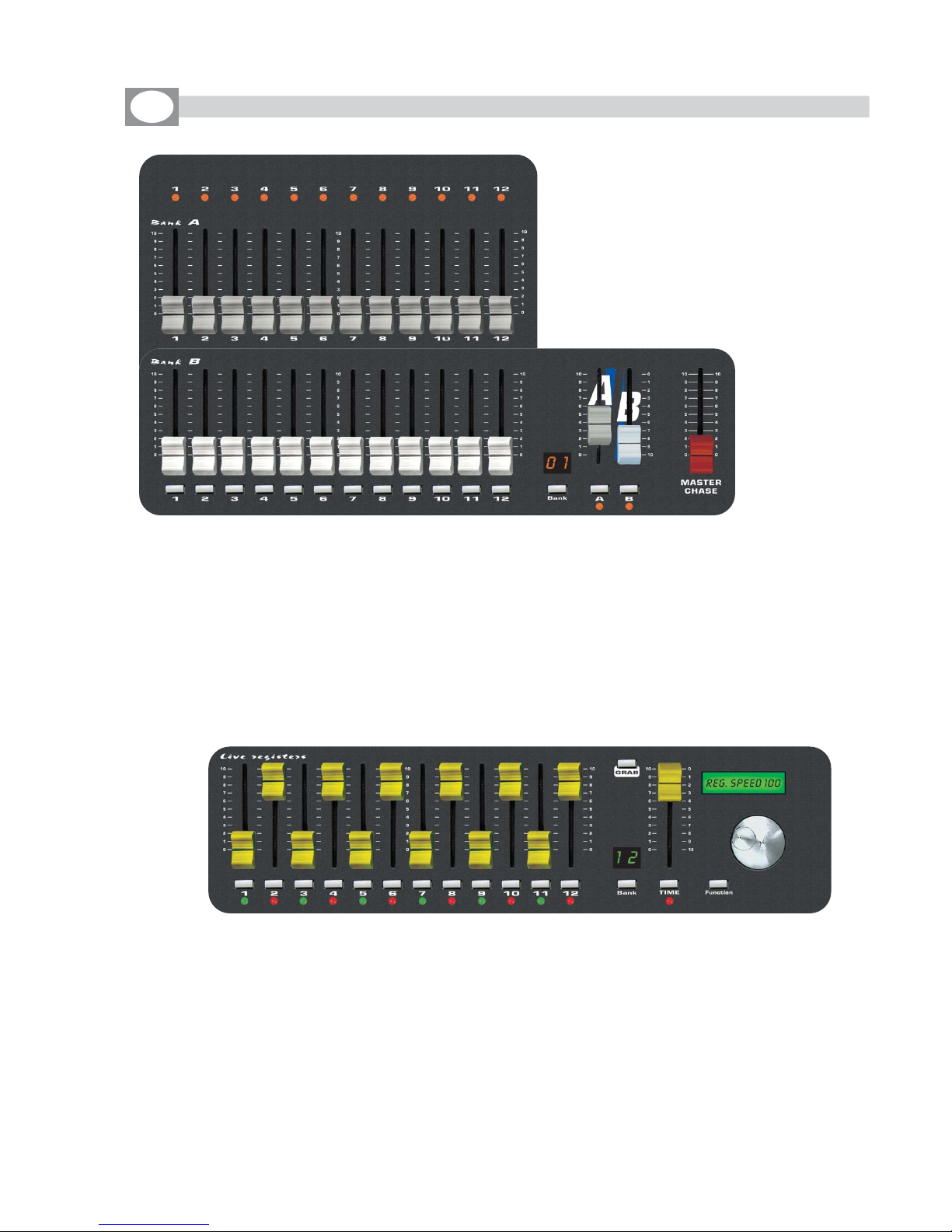
1.1 DESCRIPTION OF THE FRONT PANEL
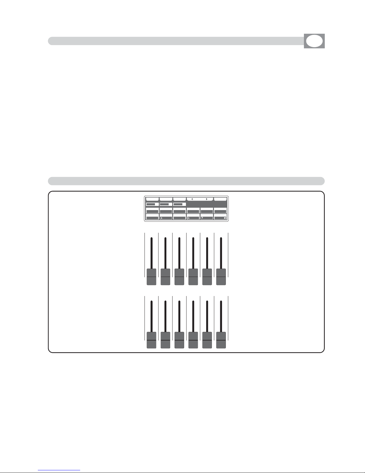
• 1 bank of 12 faders: controls the live playback registers.
• 12 keys: perform direct registers functions.
• 12 bicolor led bicolor: visualize registers status.
• TIME fader: to control stepping in real time .
• GRAB key: grab the active scene into a register.
• BANK key: to select registers page.
• Led display: visualize registers active page.
• Lcd: visualizes registers job mode..
• FUNCTION key: to set lcd functions.
• Encoder: to set lcd values.
• 2 banks of 12 faders : to control two presets A+B.
• 12 keys: perform flash on the channels.
• 12 led: Visualize the channels status.
• A+B faders: to control presets A+B level output.
• Master Chase fader: to control Chase level output.
• A+B keys: to enable presets A and B (A+B mode) or to switch
the flash buttons of the presets from one bank to the other (single
preset mode)
• BANK key: to select the preset page max 12.
• Led display: Visualize the active preset page.
Manual presets:
Live registers:

• 12 faders: to control the functions shown on the display.
• 1 Grand Master fader: general control of output levels.
• 6 function keys: to select the functions shown on the display.
• 1 Menu/OK key: accesses to menu/ok functions.
• 1 Esc key: to go back.
• 1 Manual key: to control unit.
• 1 Joy speed key: Active the moving Joystick speed from 1 to 10 fixed or
proportional type.
• 12 Multifunction keys: to select the functions shown on the display.
• 5 Mode keys: to select selezionano the modality SCENE / PROGRAM /
CHASE / EFFECT GENERATOR / REGISTERS.
• 1 Page key: changes the active page.
Intelligent fixture control:

Verify the contents of the packing.
If one of the following parts of the packing is missing or damaged, please,
contact your dealer immediately.
• Matrix Live
• User’s manual.
• Warranty
• 1 XLR 5 P male connector
• 1 AC adapter mod. 1890581
• 1 Cable for AC adapter
• 1 Cable male/female RS 232
• 2 USB Lamp
• 2 Knob to tilt Matrix Live
Read the following warnings before beginning installation.
• This unit is not intended for home use.
• Read this manual thoroughly and observe the following precautions before working
with the controller.
• Take care not to spill liquids on to the controller and do not use it in excessively humid
conditions.
• Do not install the controller near heat sources or expose it to direct sunlight and do
not install in dusty environments without suitable protection.
• Do not use the controller unless the mains cable and plug are in perfect condition
(replace or repair if necessary).
• Do not use solvents such as acetone or alcohol to clean the controller or the finish
and panel lettering will be damaged.
• If a fault occurs, consult your nearest service centre or a specialized light equipment
repair service. Do not attempt to repair the controller yourself.
1.2
ACESSORIES AND DOCUMENTATION PROVIDED WITH THE EQUIPMENT
GB

DMX 512
1 = GND
2
=
-
DATA OUT
3
=
+
DATA OUT
4
=
-
DATA IN
5
=
+
DATA IN
POWER
POWER-IN
9 VDC - 1,2 A
1 = GND
2 = +VDC
AUDIO IN
(0 dB)
SD CARDRS 232
MIDI
IN THRU OUT
DMX
W
i
inside!
®
ON OFF
MIC
0122
!
FCC ID:
R8KUGWR2USXXXX
www.wi-dmx.com
15
3
42
2.1 DESCRIPTION OF THE REAR PANEL
1
0 dB audio signal INPUT with a mono/stereo jack connector.
2
MICROPHONE for the
MMUUSSIICC
function
3
4
MIDI
12 Vac power INPUT with a 3-pin cannon connector.
5
POWER KEY
6
Standard DMX 512 signal INPUT/OUTPUT with a 5-pin cannon connector.
7
RS232 signal INPUT.
8
SD card slot
9
Antenna for built in WI-DMX wireless Transmitter
1 2 43 6 7 8 95
GB
2.2 INPUT CONNECTION FOR POWER SUPPLY
2.3 CONNECTION OF THE AC ADAPTER TO THE MAIN AC
Plug the 3-pin cannon connector of the AC adapter completly in the power
input
Use the “push” safety hook to disconnect it and extract it gently.
ATTENTION: do not use AC adapter different from the one supplied, it could
cause serious damages at the internal circuitation.
Do not connect the 3-pin cannon connector in other appliances, it has been
studied to be used only in this controller.
4
MAKE SURE THAT VOLTAGE AND POWER FREQUENCY CORRESPOND TO
WHAT IS REPORTED ON THE AC ADAPTER PLATE.
Press
POWER
key to verify the correct installation.
If pressing the
POWER
key no leds light up, please check if there is tension in
the electric socket or check the connection between AC adapter-controller and
AC adapter-electric socket.
If the problem persists, please consult your dealer.
®
3.1 FIRST USE OF THE UNIT
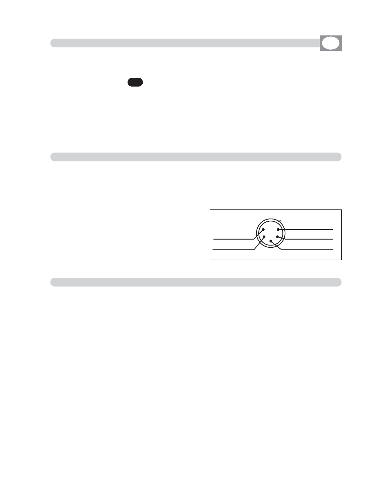
2.4 DMX 512 OUTPUT/INPUT CONNECTION
Make sure you are using shielded twisted cables suitable for the transmission of the
DMX 512 signal with connectors of good quality and connection as shown on the
side of the connector.
Plug the 5-pin XLR connector coming from the unit completly in the DMX 512 output
Use the “push” safety hook to disconnect it and than extract it gently.
ATTENTION: the shielded part of the cable must never be connected to the ground of
the electrical system as this could cause faults during the working of the controller
6
2.5 EXAMPLE OF DMX 512 LINE CONNECTION
MATRIX has a DMX 512 input/output that uses standard XLR 5-pin connector The
input it is for now disabled from the software.
The cable must have shielded with these characteristics:
- 2 conductors plus screen
- 120 Ohm impedance
- low capacity
- maximum transmission rate 250 Kbaud.
For the connection do reference to the figure.
MMAATTRRIIXX
is a universal DMX controller and is provided with an initial generic configuration.
For a correct operation
YYOOUU MMUUSSTT
configure the controller with the type of projectors/scanner connected to it.
The
SETUP LIBRARY
sheet includes the list of the projectors/scanner contained in
the internal memory of the controller, if the requested configuration is not present
in the library, you need to make a personalized one.
The operations to configure the controller is described in the user’s manual at
chapter:
10.7 Function
MENU: EDIT DMX PATCH
MMAATTRRIIXX
is endowed with graphic display with adjustable contrast from menù, if the
initial setting isn’t correct, it is possible to change the contrast.
The operations to
change contrast
is described in the user’s manual at chapter:
10.14 Function
MENU: SYSTEM SETTINGS
15
3
42
XLR 5-pin
Common
-
DMX OUT
+
DMX OUT
-
DMX IN
+
DMX IN
GB
PPRROOGG
CC OO PP YY EE RR AA SS EE TT IIMM EE
00 00 22 ss 00 55 00 %%
FFAADDEE 000011
TT 000022 005500%%
EEFF 0055
TT 000044 007700%% TT 001100 003300%% TT 005500 004400%% TT 002200 007700%% TT 000044 007700%%
LL AA SSTT EE DD IITT EEFFFF EECCTT
0011
EEFFFFTT
0055
SSCCEENN
0022
0011 0022 0033 0044 0055 0066
0077 0088 0099 1100 1111 1122
Scene
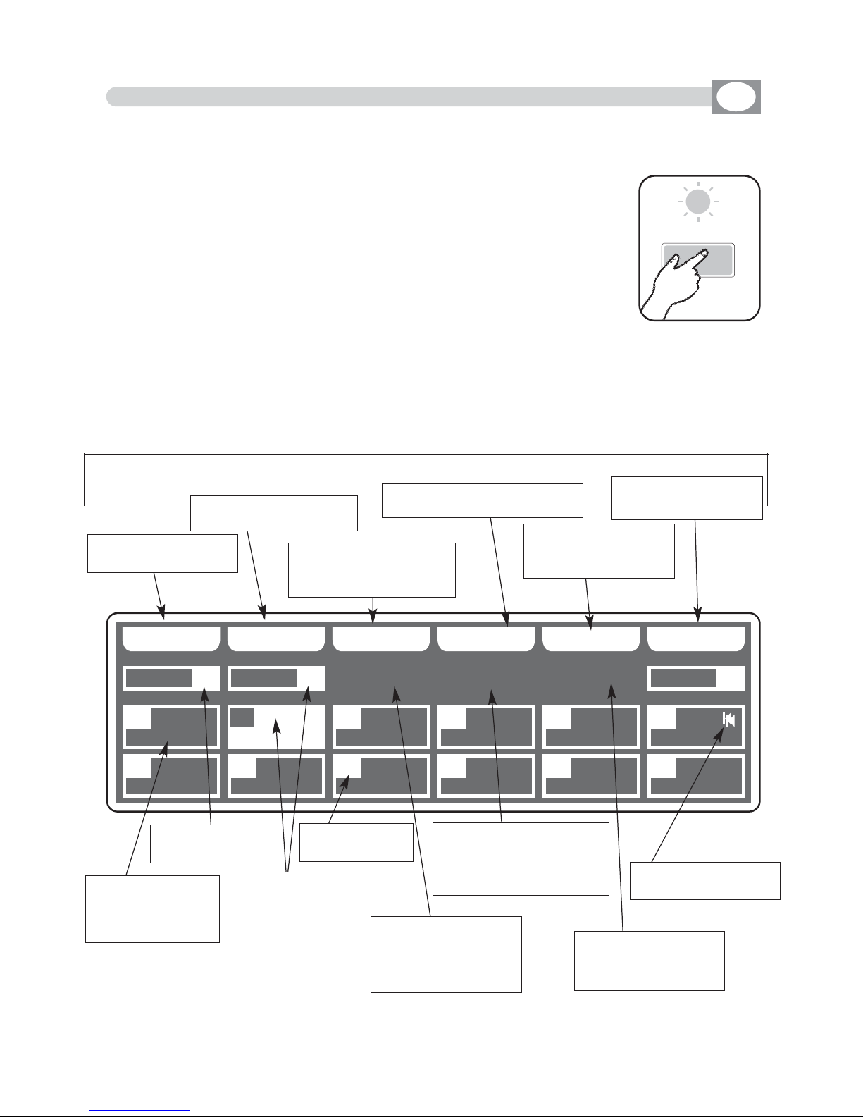
4.1 SCENE MODE
GB
Press SCENE key to activate
SCENE
function
(Fig. 1)
The SCENE key led will light up to indicate the activation of this
function, and the display changes as shown in (Fig. 2)
The graphic display indicates the scene (
hhiigghhlliigghhtteedd
) currently active
(Fig. 2) if an empty scene is selected, on the display appears
“
FFRREEEE
SSCCEENNEE
”.
THIS FUNCTION ALLOWS TO SEE ONE OF THE 48 SCENES
OF THE ACTIVE
PROGRAM
,
CHANGE THE PARAMETERS AND EDITING.
Press one of the 1÷12 keys to select the scene.
Pushes it again, the scene puts on out his end value.
For scenes 13÷24/25÷36/37÷48 use the
PPAAGGEE
key
Note: Keep Master Dimmer Faders to the maximum (see par 6.11)
Function Keys
see par 4.2
Fig. 1
Fig. 2
Key to copy the active
scene
Key to erase the active
scene
Key to modify the total
time of the active scene
Key to mark
the last scene of the program
Key to create or
modify the active
scene
visualize total time
and percent of
transition of the
scene
visualize the
active program
visualize the
active scene
with effect n°05
indicate the
scene number
indicates the total
time of the active
scene, in seconds
from 1 to 600
indicates the time to transition of the active scene
as percent of the total
time
indicates the time to
transition in seconds
from 0 to 600
indicates the last
scene of the program
Key for add an effect
to the active scene
4.2 FUNCTION KEYS IN SCENE MODE
GB
In
SSCCEENNEE
mode there are 6
ffuunnccttiioonn kkeeyyss
see (Pic. 2 par
44..11
).
COPY
Key:
Press this key to copy the active scene on a free scene of the same program: the display shows
""SSEELLEECCTT DDEESSTTIINNAATTIIOONN SSCCEENNEE,,""
select through the 1÷12 keys the destination of the copy.
For the successive scenes use
PPAAGGEE
key
NNoottee
: After have pressed
CCOOPPYY
key, the same becomes
GGRRAABB
key.
GRAB
Key: active only pressing
COPY
key
Press this key to store, the scene; you can then paste it in an empty scene of the same program
or in a diferent program. The key becomes
PPAASSTTEE
.
ALL
Key: active only pressing
COPY
key
Press this key to copy all the scenes of the active program to another program: the display shows
""SSEELLEECCTT DDEESSTTIINNAATTIIOONN PPRROOGGRRAAMM,,""
select through the 1÷12 keys the destination of the copy.
For the successive program use
PPAAGGEE
key
PASTE
Key: active only pressing in empty scene
Pressing this key the scene previously stored could be pasted to an any empty scene of any program.
ERASE
Key:
Press this key to the erase active scene, select through the 1÷12 keys (for the successive scenes
use
PPAAGGEE
key) the scene that must be erased, then press the
EERRAASSEE
key.
The scene will erased in a permanent way, it is not possible recover it.
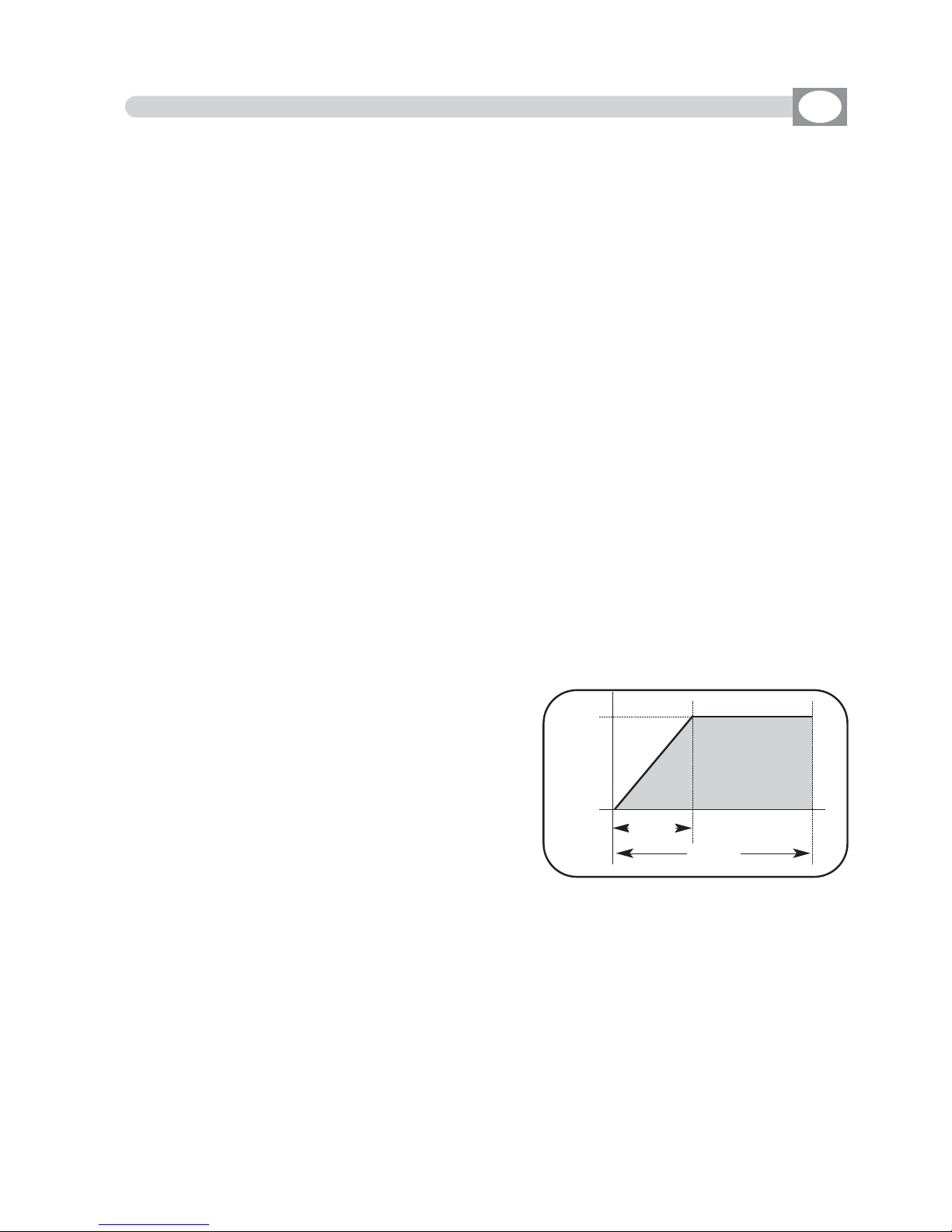
TIME
Key:
Press this key to change the total time of the scene, the value is in seconds from 1 to 600, use
the fader under the
TTIIMMEE
writing, or the encoder. To confirm the modify press the
OOKK
key, to get
out of the function press the
EESSCC
key.
CROSS
Key: active only pressing
TIME
key
Press this key to modify the time of transition of the
scene, the value is express in percent from 0 to 100%,
use the fader under the
CCRROOSSSS
writing, or the encoder.
To confirm the modify press the
OOKK
key, to get out of
the function press the
EESSCC
key.
TO ALL
Key: active only pressing
TIME
key
Press this key to set equal values for all the scene .
LAST
Key:
Press this key to select the last scene of the program,
select through the 1÷12 keys (for the successive scenes
use
PPAAGGEE
key) the scene where you want to terminate the program, then press the
LLAASSTT
key.
For the successive scenes use
PPAAGGEE
key
NNoottee
: The last scene of the program will be stored automatically in
EEDDIITT
mode.
EDIT
Key:
Press this key to create/modify the active scene see par. 4.3
EDIT IN SCENE mode
EFFECT
Key
:
Press this key to set a shape genarator for the active scene, for creation of an effect see par 7.5
EDIT EFFECT
mode.
SCENE
Value
SCENE
CROSS
TIME

4.3 EDIT IN SCENE MODE
GB
The graphic display indicates the scene (
hhiigghhlliigghhtteedd
) currently active
(Fig. 2 par
44..11
)
to create/modify it press the
EDIT
key (Fig. 3).
The display changes as shown in (Fig. 4).
THIS FUNCTION ALLOWS TO EDIT ONE OF THE 48 SCENES OF THE ACTIVE PROGRAM.
Fig. 3
EE DD II TT
PPRROOGG
SSAA VV EE UU NN DD OO MM AA SS KK
006600
009900 007700 002200 225555 000000 225555
114400 225555
UU NN II TT SSEELLEECC TT
0011
SSCCEENN
0022
UUNNIITT
0011
PPAANN TTIILLTT CCOOLLOOUURR
005500 000000 110000
CCYYAANN MMAAGGEENNTTAA YYEELLLLOOWW
DDIIMMMMEERR SSHHUUTT//SSTTRR ZZOOOOMM MM--SSPPEEEEDD CCOOLL..MMOODDEE CCOOLLOOUURR 22
SSGG MM GG II OO TT TT OO WW .. 44 00 00
Fig. 6
Key to save the scene
Key to go back to the
saved scene
key to mask determined
channels
select the units to
modify
Shows name of the unit,
if more than one shows
“
NNNN UUNNIITTSS””
Unit selection see par
44..44
Shows the DMX
channel value
Shows the active program
Shows the scene in
modification
Shows the name
of the channel
Indicate that the faders
aren’t in the position of
the value, keep it in the
sense of the arrow to
catch the value
Indicate the unit from
which are taken the
channels
Indicate that the value
can be modified with
the encoder

4.4 SELECT IN EDIT SCENE MODE
GB
ALL
Key
:
Press this key to select all the units previously assign to the program, it isn’t
possible select unit if not active in the program.see par. 5.2
.
Pressing this key the display shown “
NNNN UUNNIITTSS
”, the DMX control channels will
taken from the unit shown in the box
UUNNIITT ....
SOLO
Key
:
Press this key to select only the unit shown in the box
UUNNIITT ....
, if we have
selected with the
AALLLL
key all the
4488
unit, and we wants to change the value of
the unit channels (es. n°
0022),,
press
twice
the key
0022
of selection unit. The unit
box will indicate
UUNNIITT 0022
now the
SOLO
key unselect all the other unit, acti-
vating
SOLO
the
UUNNIITT 0022
DONE
Key
:
Pressing this key you confirm the selection of the unit see par. 4.5.
PPRROOGG
AA LLLL SS OOLLOO
MM AARR RR OO BB OO CCOO LLOO RR II II XX
RROOBBOOCCOOLL II
MMAARR CCPP
GGIIOOTTTTOO WW.. SSUUPPEERR SSCCAA
SSGGMM
DD OONN EELL OO CC AA TT EE
0011
SSCCEENN
0022
UUNNIITT
0011
00220011 0033 0044 0055 0066
0077 0088 0099 1100 1111 1122
To activate the
multiple selection of the unit
press the
SELECT
key (
Fig. 4 par
44..33
).
The display changes as shown in (Fig. 5).
THIS FUNCTION ALLOWS TO SELECT ONE OR MORE UNIT OF THE ACTIVE
PROGRAM.
Press one of the 1÷12 keys to ativate one or more the unit.
To successive units use the
PPAAGGEE
key
Fig. 5
Key to select all the
active unit of the program
Key to select only the
unit shown on
UUNNIITT
Key to locate the selected unit
Key to confirm the
selection see par
4.5
Shows short name
of the unit previously loaded from
internal library
see par.
10.6
Shows the active program
Shows the
active scene
Indicate the
number of unit
Indicate the last selected unit see par
4.4
Shows name of the unit,
if are more of one it
Shows “
NNNN UUNNIITTSS””
empty box indicate
that no unit loaded
from internal library
see par.
10.6

Through the 12 faders you regulate the value of corresponding channel see par
44..77
Pressing one of the 1÷12 keys the correspondent channel can be modified with
the encoder.
For successive channels use the
PPAAGGEE
key
PPRROOGG
SSAA VV EE UU NN DD OO MM AA SS KK
006600
009900 007700 002200 225555 000000 225555
114400 225555
UU NN II TT SSEELLEECC TT
0011
SSCCEENN
0022
UUNNIITT
0011
PPAANN TTIILLTT CCOOLLOOUURR
005500 000000 110000
CCYYAANN MMAAGGEENNTTAA YYEELLLLOOWW
DDIIMMMMEERR SSHHUUTT//SSTTRR ZZOOOOMM MM--SSPPEEEEDD CCOOLL..MMOODDEE CCOOLLOOUURR 22
SSGG MM GG II OO TT TT OO WW .. 44 00 00
4.5 EDIT SCENE MODE
GB
THIS FUNCTION ALLOWS TO MODIFY THE VALUE OF THE CHANNELS OF THE
UNITS SELECTED
Fig. 6
Key to save the scene
Key to go back to the
saved scene
key to mask determined
channels
select the unities to
modify
Shows name of the unit,
if more than one shows
“
NNNN UUNNIITTSS””
Unit selection see par
44..44
Shows the DMX
channel value
Shows the active program
Shows the scene in
modification
Shows the name
of the channel
Indicate that the faders
aren’t in the position of
the value, keep it in the
sense of the arrow to
catch the value
Indicate the unit from
which are taken the
channels
Indicate that the value
can be modified with
the encoder
The 12 faders are used to adjust the channels value see (Fig. 7)
To modify the scene, keep the faders to desired values.
Each time that changes page the faders remains inactive.
The arrow in the box ndicate that the fader aren’t in the position of the value, keep it in
the sense of the arrow to catch the value. If you select more unit at the same time, the
names of the channels and the suitable values do reference to the unint signalled from
the box unit.
YYoouu ccaann nnoott mmooddiiffyy tthhee vvaalluuee ooff tthhee cchhaannnneellss:: PPAANN LLOOWW // TTIILLTT LLOOWW //
LLAAMMPP // LLAAMMPP--RREESS
. To modify the value see par 10.6
PPRROOGG
SS AA VVEE UUNN DDOO MMAASS KK
009900
225555
007700
000000
002200
110000
113355
113355
000000
000000
225555
225555
UU NN II TT SS EELL EECC TT
0011
SSCCEENN
0022
UUNNIITT
0011
DDIIMMMMEERR SSHHUUTT//SSTTRR ZZOOOOMM
PPAANN TTIILLTT CCOOLLOOUURR
MM--SSPPEEEEDD CCOOLL..MMOODDEE CCOOLLOOUURR 22
CCYYAANN MMAAGGEENNTTAA YYEELLLLOOWW
SS GG MM GG II OOTT TT OO WW.. 440000
Fig. 7
4.6 FUNCTION KEYS IN EDIT SCENE MODE
In EDIT SCENE mode there are 6
ffuunnccttiioonn kkeeyyss
see (Fig. 6 par
44..55
).
SAVE/
UPDATE
key
:
Press the
SAVE
key to save the free scene and go to the next free scene
The
UPDATE
key allow you to update the saved scene and go back to the scene function
see par
44..11
UNDO
key: it works only on saved scenes
Pressing this key you go back to the saved scene
MASK
key
:
Press this key to activate the mask function. see par
44..88
UNIT
key
:
Press this keys to select the successive/precedent unit
SELECT
key
:
Pressing this key you go back to the unit selection see par
44..33
4.7 CHANNELS ADJUSTMENT FADERS IN EDIT SCENE MODE
GB

Fanout key
Using the joystick the PAN and TILT channels of the
scanner’s mirror and and moving heads can be adjusted (Fig.8).
The joystick type is with central return, thanks to the
sophisticated software of management, it allows an
easy and exact positioning.
The mirror’s speed movement could be changed
through the Joy speed key
Every time you press the Joy speed key the selected
speed it is shows for 3 seconds on the graphic display
(Fig. 9).
With SPEED 01/10 the joystick moves the mirror
with a fixed speed, with SPEED PROP joystick become
proportional type, if you leave the joystick in central
position the mirror keeps still; whereas the more you
move it away from the centre the faster the mirror
will run.
Pressing twice the Joy speed key joystick passes directly
to the fine movement mode.
The
Joy speed
key led will light up to indicate the activation of this function.
Useful function for control moving heads
The FANOUT key appears only if you have selected more than one unit, press this key
to move selected units as a fan.
Joystick movement change the PAN/PAN LOW and TILT/TILT LOW output channels.
4.8 PAN AND TILT CHANNELS ADJUSTMENT THROUGH THE JOYSTICK
Fig. 8
Fig. 9
GB
Joy speed
PPRROOGG
SSAA VV EE UU NN DD OO
FFAA NN OO UU TT
006600
009900 007700 002200 113355 000000 225555
114400 225555
JJ OO YY SS PP EEEEDD :: PP RR OO PP
0011
SSCCEENN
0022
UUNNIITT
0011
PPAANN TTIILLTT CCOOLLOOUURR
005500 000000 110000
CCYYAANN MMAAGGEENNTTAA YYEELLLLOOWW
DDIIMMMMEERR SSHHUUTT//SSTTRR ZZOOOOMM MM--SSPPEEEEDD CCOOLL..MMOODDEE CCOOLLOOUURR 22
SSGG MM GG II OO TT TT OO WW .. 44 00 00
keys to change the speed
indicates the the setting out of speed

PPRROOGG
SSAA VV EE UU NN DD OO II NN VV EERR TT
006600
009900 007700 002200 113355 000000 225555
====== 225555
0011
SSCCEENN
0022
UUNNIITT
0011
PPAANN TTIILLTT CCOOLLOOUURR
====== ====== ======
CCYYAANN MMAAGGEENNTTAA YYEELLLLOOWW
DDIIMMMMEERR SSHHUUTT//SSTTRR ZZOOOOMM MM--SSPPEEEEDD CCOOLL..MMOODDEE CCOOLLOOUURR 22
MMAASSKK CCHHAANNNNEELLSS......
4.9 MASK FUNCTION IN SCENE MODE
GB
Press
MASK
key to activate
MASK
function
(Fig. 10)
The display changes as shown in (Fig. 11)
The graphic display indicates the channels masked with the symbol"==="
(Fig. 11)
The operator in this case masks the tilt, cyan, magenta and yellow
channels. When you recall the scene The masked channels stay to
the value planned in precedence.
Very useful function for create scenes that make only change color etc.
THIS FUNCTION ALLOWS TO MASK THE CHANNELS OF THE PREVIOUSLY SELECTED UNIT IN A DETERMINED SCENE.
Fig. 10
MM AA SS KK
Fig. 11
Press one of the 1÷12 keys to masks the correspondent
channels
.
For successive channels use the
PPAAGGEE
key
INVERT
key:
Press this key to reverse the selection of the actual mask, in the case of the
(Fig. 9)
tthhee ttiilltt,, ccyyaann,, mmaaggeennttaa aanndd yyeellllooww cchhaannnneellss bbeeccoommeess mmooddiiffiiaabbllee,, wwhhiillee
tthhee ootthheerrss ccoommeess mmaasskkeedd
.
Key to save the mask
of the scene
Key to return to the
mask of the saved scene
reverses the selection of
her actual mask
indicates that we are
inside at the function of
masking
Shows the scene that
we are masking
Shows the masked channel

Manual
Press MANUAL key to activate
MANUAL
function (Fig. 12).
The MANUAL key led will light up to indicate the activation of
this function, and the display changes as shown in (Fig. 13).
The graphic display indicates the channels masked with the
symbol"===" through the 12 faders, the joystick or the 1÷12
keys the touched channel could be modified, also if the same
is inside of a program in play.
No modification for the others
In
MANUAL
mode there are 4
ffuunnccttiioonn kkeeyyss
see (Fig. 13).
GRAB
Key
:
Press this key to store the scene, you can then paste it in an empty scene of any program.
UNIT
Keys
:
Press this keys to select the successive/precedent unit
SELECT
Key
:
Press this key
for select the unit to control.
FREE
Key: active only pressing
SELECT
key
Pressing this key the selected units
become free.
CATCH
Key: active only pressing
SELECT
key
Pressing this key
Key
the selected units
will stop in the current position.
LOCATE
Key: active only pressing
SELECT
key
Press this key
to locate
the selected units
DONE
Key: active only pressing
SELECT
key
Pressing this key to confirm.
Fig. 12
4.10 MANUAL MODE
GB
THIS FUNCTION ALLOWS TO ACTIVATE ONE OR MORE UNIT WHILE THE
NOT SELECTED ONES GO ON PERFORMING THE OWN FUNCTION.
UUNNIITT
GG RR AA BB
======
====== ====== ====== ====== ====== ======
====== ======
UU NN II TT SSEELLEECC TT
0011
PPAANN TTIILLTT CCOOLLOOUURR
====== ====== ======
CCYYAANN MMAAGGEENNTTAA YYEELLLLOOWW
DDIIMMMMEERR SSHHUUTT//SSTTRR ZZOOOOMM MM--SSPPEEEEDD CCOOLL..MMOODDEE CCOOLLOOUURR 22
SSGG MM GG II OO TT TT OO WW .. 44 00 00
key to store the
scene
select the units to
control
Shows name of the unit,
if more than one shows
“
NNNN UUNNIITTSS””
select the units
with functions
FFRREEEE,,
CCAATTCCHH,, LLOOCCAATTEE
Fig. 13

PPRROOGG
GG RR AA BB LL II VV EE RR EEPPEEAA TT
0033 3300
MMUUSSIICC OONN
RRPPTT 5500
LLEENN 4400
RRPPTT 11
LLEENN 3300
RRPPTT 22
LLEENN 3300
RRPPTT 11
LLEENN 4400
RRPPTT 11
LLEENN 0055
RRPPTT 22
LLEENN 0055
RRPPTT 55
LLEENN 0055
RRPPTT 0033
LLEENN 3300
RRPPTT 11
LLEENN 0055
RRPPTT 0033
LLEENN 0055
RRPPTT 0033
LLEENN 0055
RRPPTT 0033
LLEENN 0055
LL EENN GG TT HH
MM UU SS II CC UU NN II TTSS
0022
0011 0022 0033 0044 0055 0066
0077 0088 0099 1100 1111 1122
5.1 EDIT PROGRAM MODE
GB
Press
PROGRAM
key to activate
PORGRAM
function.
(Fig. 14)
The
PROGRAM
key led will light up to indicate the activation of this
function, and the display changes as shown in
(Fig. 15).
The graphic display indicates the program (
hhiigghhlliigghhtteedd
) currently active
(Fig. 15).
THIS FUNCTION ALLOWS TO ACTIVATE A PROGRAM AND CHANGE THE PARAMETERS OF THE SAME.
A PROGRAM IS A SEQUENCE OF SCENES (STATIC) , EXECUTE IN SEQUENCE
FROM 1 TO MAX 48.
Press one of the 1÷12 keys to select the program.
For successive programs use the
PPAAGGEE
key.
Function Keys
see par 5.2
Fig. 14
Fig. 15
the repetition of the
active program from
1 to 99
Indicate if the program is in
musical with
MMUUSSIICC OONN//OOFFFF
Indicate if the program
is in musical with
NNOOTTAA
Indicate the length of the
active program from 1 to 48
the number of
the program
Shows the active program
Shows with
RRPPTT
how
many times to repeat
program and with
LLEENN
the length
Indicate that the
program is in stop
Key to start the
program
Key to select more
programs
Key to modify the repetition of the program
Key to modify the length
of the program
Key activate the program in
musical mode
Key to select the unit
that must work in the
program
Program

5.2 FUNCTION KEYS IN EDIT PROGRAM MODE
GB
In EDIT PROGRAM mode there are 6
ffuunnccttiioonn kkeeyyss
see (Fig. 15 par
55..11
)
GRAB
key
:
Press this key to transfer a chase in one register,
press one of the 1÷12 keys to confirm
LIVE
key
:
Pressing this key the display change to start chase
GO
key
:
Press this key to start the program.
Note: Keep Master Dimmer Faders to the maximum (see par 6.11)
The key becomes
PAUSE
the display changes as shown in
(Fig. 15 par
55..33
)
PAUSE
key
:
Press this key to stop the program in the current position, pressing the
GGOO
key it reco-
vers from the same position.
SELECT
key
:
Pressing this key it is possible the multiple selection of the programs.The display changes as shown in
(Fig. 14) see par
55..33
Press one of the 1÷12 keys to select the program.
For successive programs use the
PPAAGGEE
key.
REPEAT
key
:
Press this key to modify the number of repetitions of the program, the value is in number from 1 to 99 use the faders under the
REPEAT
writing, or the encoder. To confirm
the modify press the
OOKK
key, to get out of the function press the
EESSCC
key.
LENGTH
key
:
Press this key to set how many scenes of the program will execute, the value is in number from 1 to 48 use the faders under the
LENGTH
writing, or the encoder. To confirm
the modify press the
OOKK
key, to get out of the function press the
EESSCC
key.
MUSIC
key
:
Pressing this key, and activating
MMUUSSIICC OONN
, the active program will change the scenes
to time of music, in the box of the program and to the side at symbol play the display
shows a note.
The internal music sensor has an automatic gain adjustment which allows to have a
signal level good for
Matrix
working.
The input music signal is a 0dB mono/stereo so it could be taken from sound sources
like Mixer, CD, Dat etc.
UNITS
keys
:
Press this key to set what unit will be active in the program.
For successive units use the
PPAAGGEE
key.

PPRROOGG
PP AA UU SS EE
SSTT OO PP AA LLLL
RRPPTT 11
LLEENN 3300
RRPPTT 11
LLEENN 0055
RRPPTT 22
LLEENN 0055
RRPPTT 55
LLEENN 0055
RRPPTT 0033
LLEENN 3300
RRPPTT 0033
LLEENN 0055
RRPPTT 0033
LLEENN 0055
SSOO LLOO
0022
RRPPTT
0033
SSCCEENN
0011
0022
RRPPTT 0033
LLEENN 3300
0033
RRPPTT 0033
LLEENN 3300
0088
RRPPTT 0033
LLEENN 3300
0099
RRPPTT 0033
LLEENN 3300
0055
RRPPTT 0033
LLEENN 3300
0011 0044 0066
0077 1100 1111 1122
SSPP EEEEDD
11 00 00 %%
5.3 SELECT IN PROGRAM MODE
GB
To activate the multiple selection of the programs you must press the
SELECT
key
(Fig. 16).
The display changes as shown in
(Fig. 17).
THIS FUNCTION ALLOWS TO SELECT A SERIES OF PROGRAMS
Fig. 16
SSEELLEECC TT
Fig. 17
Press one of the 1÷12 keys to select more programs.
For successive programs use the
PPAAGGEE
key.
Key to set the program in pause
Key to set the program
in stop and get out of
the function
key to select all the programs
Key to select only the
program shows on
PPRROOGG
Keys to increase/decrease
the speed of execution of
the program
the repetition of the
active program from
1 to 99
the speed of execution from
10% to 500%
Indicate if the program is in musical
with
NNOOTTAA
the active scene
the number of
the program
Shows the active
programs
Shows with
RRPPTT
how
many times to repeat
program and with
LLEENN
the length
Indicate that the program is in musical
with
NNOOTTAA

5.4 FUNCTION KEYS IN PROGRAM MODE
GB
In PROGRAM mode there are 6
ffuunnccttiioonn kkeeyyss
see (Fig. 17 par
55..33
).
PAUSE
key
:
Press this key to stop the program in the current position, pressing the
GGOO
key
it recovers from the same position.
STOP
key
:
Press this key to stop the program with return to the function edit program
see (par
55..11
), pressing the
GGOO
key it start from
the first scene.
ALL
key
:
Press this key to select all the program from 1 to 48.
SOLO
key
:
Press this key to select only the program shown in the box
PPRROOGG
, if we have
selected with the
AALLLL
key all the
4488
program, and we wants to selectd only the
program (es. n°
0022),,
press
twice
the key
0022
of program selection. The prog
box will indicate
PPRROOGG 0022
now the
SOLO
key unselect all the other program,
activating
SOLO
the
PPRROOGG 0022
SPEED
key
:
Pressing one of these two keys will be increased/decreases the speed of execution
of the program the value is in percent and varied from 10% at 500%.
To the value 100%. the speed of execution is that planned in the scenes.

CCHHAASS
GG OO !! SS EE LLEECC TT RR EEPP EEAA TT
0033 3300
MMUUSSIICC OONN
RRPPTT 5500
LLEENN 4400
RRPPTT 11
LLEENN 3300
RRPPTT 22
LLEENN 3300
RRPPTT 11
LLEENN 4400
RRPPTT 11
LLEENN 0055
RRPPTT 22
LLEENN 0055
RRPPTT 55
LLEENN 0055
RRPPTT 0033
LLEENN 3300
RRPPTT 11
LLEENN 0055
RRPPTT 0033
LLEENN 0055
RRPPTT 0033
LLEENN 0055
RRPPTT 0033
LLEENN 0055
LL EENN GG TT HH
MM UU SS II CC SSTT EEPP SS
0022
0011 0022 0033 0044 0055 0066
0077 0088 0099 1100 1111 1122
6.1 CHASE MODE
GB
Press CHASE key to activate
CHASE
function
(Fig. 18)
The CHASE key led will light up to indicate the activation of this
function, and the display changes as shown in (Fig. 18).
The graphic display indicates the chase (
hhiigghhlliigghhtteedd
) currently active
(Fig. 19).
THIS FUNCTION ALLOWS TO ACTIVATE A CHASE AND CHANGE THE PARAMETERS OF THE SAME.
A CHASE IS A PLAY OF LIGHTS, IT IS A SEQUENCE OF STEPS
(FROM 1 TO 48 MAX).
Press one of the 1÷12 keys to select the chase.
For successive chases use the
PPAAGGEE
key
Function Keys
see par 6.2
Fig. 18
Fig. 19
the repetition of the
active chase from 1
to 99
Indicate if the chase is in
musical with
MMUUSSIICC OONN//OOFFFF
Indicate if the chase i
in musical with
NNOOTTAA
Indicate the length of the
active chase from 1 to 48
the number of
the chase
Shows the active chase
Shows with
RRPPTT
how
many times to repeat
chase and with
LLEE NN
the length
Indicate that the
chase is in stop
Key to start the
chase
Key to select more
chase
Key to modify the repetition of the chase
Key to modify the length
of the chase
Key activate the chase
in musical mode
Key to select the step
see par
66..55
Chase

6.2 FUNCTION KEYS IN EDIT CHASE MODE
GB
In EDIT CHASE mode there are 6
ffuunnccttiioonn kkeeyyss
see (Fig. 19 par
66..11
)
GRAB
key
:
Press this key to transfer a chase in one register,
press one of the 1÷12 keys to confirm
LIVE
key
:
Pressing this key the display change to start chase
GO
key
:
Press this key to start the chase.
Note: Keep Master Dimmer Chase to the maximum see (par 6.12)
The key becomes
PAUSE
the display changes as shown in
(Fig. 21 par
66..33
)
PAUSE
key
:
Press this key to stop the chase in the current position, pressing the
GGOO
key it recovers
from the same position.
SELECT
key
:
Pressing this key it is possible the multiple selection of the chases.The display changes
as shown in
(Fig. 19 par
66..33
)
Press one of the 1÷12 keys to select the chase .
For successive chases use the
PPAAGGEE
key.
REPEAT
key
:
Press this key to modify the number of repetitions of the chase , the value is in number
from 1 to 99 use the faders under the
REPEAT
writing, or the encoder. To confirm the
modify press the
OOKK
key, to get out of the function press the
EESSCC
key.
LENGTH
key
:
Press this key to set how many scenes of the chase will execute, the value is in number
from 1 to 48 use the faders under the
LENGTH
writing, or the encoder. To confirm the
modify press the
OOKK
key, to get out of the function press the
EESSCC
key.
MUSIC
key
:
Pressing this key, and activating
MMUUSSIICC OONN
, the active chase will change the scenes to
time of music, in the box of the chase and to the side at symbol play the display shows a
note.
The internal music sensor has an automatic gain adjustment which allows to have a
signal level good for the
Matrix
working.
The input music signal is a 0dB mono/stereo so it could be taken from sound sources
like Mixer, CD, Dat etc.
STEPS
keys
:
Pressing this key you go in the
step mode see
par
66..55

CCHHAASS
PP AA UU SS EE
SSTT OO PP AA LLLL
RRPPTT 11
LLEENN 3300
RRPPTT 11
LLEENN 0055
RRPPTT 22
LLEENN 0055
RRPPTT 55
LLEENN 0055
RRPPTT 0033
LLEENN 3300
RRPPTT 0033
LLEENN 0055
RRPPTT 0033
LLEENN 0055
SSOO LLOO
0022
RRPPTT
0033
SSTTEEPP
0011
0022
RRPPTT 0033
LLEENN 3300
0033
RRPPTT 0033
LLEENN 3300
0088
RRPPTT 0033
LLEENN 3300
0099
RRPPTT 0033
LLEENN 3300
0055
RRPPTT 0033
LLEENN 3300
0011 0044 0066
0077 1100 1111 1122
SSPP EEEEDD
11 00 00 %%
6.3 SELECT IN CHASE MODE
GB
To activate the multiple selection of the chases you must press the
SELECT
key
(Fig. 20).
The display changes as shown in
(Fig. 21).
THIS FUNCTION ALLOWS TO SELECT A SERIES OF
CHASE
Fig. 20
SSEELLEECC TT
Fig. 21
Press one of the 1÷12 keys to select more chase.
For successive chases use the
PPAAGGEE
key.
Key to set the chase
in pause
Key to set the chase in
stop
key to select all the chases
Key to select only the
chase shows on
CCHHAASS
Keys to increase/decrease
the speed of execution of
the chase
the repetition of the
active chase from 1
to 99
the speed of execution from
10% to 500%
Indicate if the chase i
in musical with
NNOOTTAA
the active step
the number of
the chase
Shows the active
chases
Shows with
RRPPTT
how
many times to repeat
chase and with
LLEE NN
the length
Indicate that the
chase is in musical
with
NNOOTTAA

6.4 FUNCTION KEYS IN CHASE MODE
GB
In CHASE mode there are 6
ffuunnccttiioonn kkeeyyss
see (Fig. 21 par
66..33
).
PAUSE
key
:
Press this key to stop the chase in the current position, pressing the
GGOO
key it
recovers from the same position.
STOP
key
:
Press this key to stop the chase, pressing the
GGOO
key it start from
the first
step.
ALL
key
:
Press this key to select all the chase from 1 to 48.
SOLO
key
:
Press this key to select only the chase shown in the box
CCHHAASS
, if we have
selected with the
AALLLL
key all the
4488
chase, and we wants to selectd only the
chase (es. n°
0022),,
press
twice
the key
0022
of chase selection. The chase box
will indicate
CCHHAASS 0022
now the
SOLO
key unselect all the other chase, activa-
ting
SOLO
the
CCHHAASS 0022
SPEED
key
:
Pressing one of these two keys will be increased/decreases the speed of execution
of the chase the value is in percent and varied from 10% at 500%.
To the value 100%. the speed of execution is that planned in the scenes.

CCHHAASS
CC OO PP YY EE RR AA SS EE TT II MM EE
00 00 .. 22 ss 00 55 00 %%
FFAADDEE 000011
TT 000022 005500%%TT 000044 007700%% TT 001100 003300%% TT 005500 004400%% TT 002200 007700%% TT 000044 007700%%
LL AA SSTT EE DD II TT
0011
SSTTEEPP
0022
0011 0022 0033 0044 0055 0066
0077 0088 0099 1100 1111 1122
6.5 STEPS MODE
GB
Press STEPS key to activate
STEPS
function
(Fig. 22)
The display changes as shown in (Fig. 23)
The graphic display indicates the scene (
hhiigghhlliigghhtteedd
) currently active
(Fig. 23) if an empty step is selected, on the display appears
“
FFRREEEE
SSTTEEPPSS
”.
THIS FUNCTION ALLOWS TO SEE ONE OF THE 48 STEPS
OF THE ACTIVE
CHASE
,
CHANGE THE PARAMETERS AND EDITING.
Press one of the 1÷12 keys to select the step.
Pushes it again, the step puts on out his end value.
For successive step use the
PPAAGGEE
key
Note: Keep Master Chase Faders to the maximum see (par 6.12)
Function Keys
see par 6.6
Fig. 23
Key to copy the active
step
Key to erase the active
step
Key to modify the total
time of the active step
Key to mark
the last step of the chase
Key to create or
modify the active step
see par
66..77
visualize total time
and percent of
transition of the
step
visualize the
active chase
visualize the
active step
indicate the step
number
indicates the total time of
the active step, from 0,2
to 600 seconds
indicates the time to transition of the active step
as percent of the total
time
indicates the time to
transition in seconds
from 0 to 600
indicates the last step
of the chase
Fig. 22
SSTT EEPP SS

6.6 FUNCTION KEYS IN STEPS MODE
GB
In
SSTTEEPP
mode there are 6
ffuunnccttiioonn kkeeyyss
see (Pic. 2 par
44..11
).
COPY
Key:
Press this key to copy the active step on a free step of the same chase: the display shows
""SSEELLEECCTT
DDEESSTTIINNAATTIIOONN SSTTEEPP,,""
select through the 1÷12 keys the destination of the copy.
For the successive steps use
PPAAGGEE
key
NNoottee
: After have pressed
CCOOPPYY
key, the same becomes
GGRRAABB
key.
GRAB
Key: active only pressing
COPY
key
Press this key to store, the scene; you can then paste it in an empty scene of the same program
or in a diferent program. The key becomes
PPAASSTTEE
.
ALL
Key: active only pressing
COPY
key
Press this key to copy all the steps of the active chase to another chase: the display shows
""SSEELLEECCTT DDEESSTTIINNAATTIIOONN CCHHAASSEE,,""
select through the 1÷12 keys the destination of the copy.
For the successive chase use
PPAAGGEE
key
PASTE
Key: active only pressing in empty step
Pressing this key the step previously stored could be pasted to an any empty step of any chase.
ERASE
Key:
Pressing this key the active step will be erased, select through the 1÷12 keys (for the successive
chases use
PPAAGGEE
key) the step that must be erased, then press the
EERRAASSEE
key.
The step will erased in a permanent way, it is not possible recover it.
TIME
Key:
Press this key to change the total time of the scene, the value is in seconds from 0,2 to 600, use
the fader under the
TTIIMMEE
writing, or the encoder. To confirm the modify press the
OOKK
key, to get
out of the function press the
EESSCC
key.
CROSS
Key: active only pressing
TIME
key
Press this key to modify the time of transition of the
scene, the value is express in percent from 0 to 100%,
use the fader under the
CCRROOSSSS
writing, or the encoder.
To confirm the modify press the
OOKK
key, to get out of
the function press the
EESSCC
key.
TO ALL
Key: active only pressing
TIME
key
Press this key to set equal values for all the step .
LAST
Key:
Press this key to select the last step of the chase, select through the 1÷12 keys (for the successive chases use
PPAAGGEE
key) the step where you want to terminate the chase, then press the
LLAASSTT
key.
For the successive chases use
PPAAGGEE
key
NNoottee
: The last step of the chase will be stored automatically in
EEDDIITT
mode.
EDIT
Key:
Press this key to create/modify the active step see par. 6.7
EDIT IN STEP mode
STEP
value
STEP
CROSS
TIME

CCHHAASS
SSAA VV EE UU NN DD OO MM AA SS KK
006600
009900 007700 002200 113355 000000 225555
114400 225555
PP AA GG EE 33PPGG
0011
SSTTEEPP
0022
CCHH 000011..0011 CCHH 000022..0011 CCHH 000033..0011
005500 000000 110000
CCHH 000044..0011 CCHH 000055..0011 CCHH 000066..0011
CCHH 000077..0022 CCHH 000088..0022 CCHH 000099..0022 CCHH 001100..0022 CCHH 001111..0022 CCHH 001122..0022
DD II MM MM EERR SS 00 00 11 --:: 00 11 22
6.7 EDIT STEPS MODE
GB
The graphic display indicates the step (
hhiigghhlliigghhtteedd
) currently active (Fig.
23 par
66..55
)
to create/modify it press the
EDIT
key (Fig. 24).
The display changes as shown in (Fig. 25).
THIS FUNCTION ALLOWS TO CREATE OR MODIFY ONE OF 48 STEP OF
ACTIVE CHASE .
Pressing one of the 1÷12 keys the correspondent channel go to the 0 value if
it is high, to 255 value if it is low.
For successive channels use the
PPAAGGEE
key
Fig. 24
EE DD II TT
Fig. 25
Key to save the step
Key to go back to the
saved step
key to mask determined
channels
Keys to select the successive/
precedent page
indicate the shows
channels
Key to jump of 3
pages
Shows the DMX
channel value
Shows the
active chase
Shows the
ste in modification
Shows the name
of the channel
Indicate that the faders
aren’t in the position of
the value, keep it in the
sense of the arrow to
catch the value
Indicate on which
dimmer working
Indicate that the value
can be modified with
the encoder

The 12 faders are used to adjust the channels value see (Fig. 7)
To modify the step , keep the faders to desired values.
Each time that changes page the faders remains inactive.
The arrow in the box ndicate that the fader aren’t in the position of the value, keep it in
the sense of the arrow to catch the value.
To an on-off chase type use the 1÷12 keys
For successive channels use the
PPAAGGEE
key
PPRROOGG
SS AA VVEE UUNN DDOO MMAASS KK
009900
225555
007700
000000
002200
110000
113355
113355
000000
000000
225555
225555
UU NN II TT SS EELL EECC TT
0011
SSCCEENN
0022
UUNNIITT
0011
DDIIMMMMEERR SSHHUUTT//SSTTRR ZZOOOOMM
PPAANN TTIILLTT CCOOLLOOUURR
MM--SSPPEEEEDD CCOOLL..MMOODDEE CCOOLLOOUURR 22
CCYYAANN MMAAGGEENNTTAA YYEELLLLOOWW
SS GG MM GG II OOTT TT OO WW .. 4400 00
Fig. 26
6.8 FUNCTION KEYS IN EDIT STEPS MODE
GB
In EDIT
STEPS
mode there are 5
ffuunnccttiioonn kkeeyyss
see (Fig. 6 par
44..55
).
SAVE
key
:
Press this key to save the step
The
UPDATE
key allow you to update the saved step and go back to the steps function
UNDO:
it works only on saved scenes
Pressing this key you go back to the saved step
PAGE
keys
:
Press this keys to select the successive/precedent page
3PG
keys
:
Pressing this will jump of 3 pages in 3 pages.
6.9 CHANNELS ADJUSTMENT FADERS IN EDIT STEPS MODE
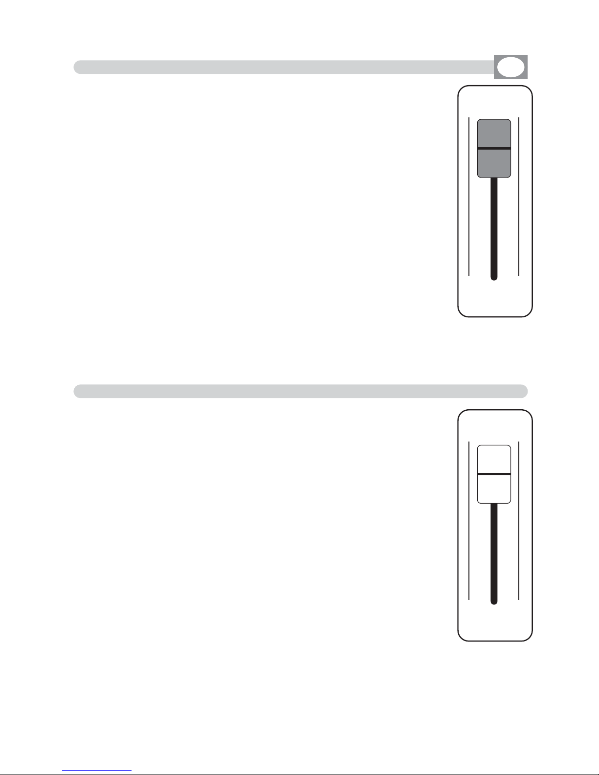
The Grand Master fader (Fig. 29) allows to adjust the bright general intensity of all the units
, (only if the connected units have
the dimmer channel).
Keep the fader always to the maximum 100%, keep to 0 value
only to create a blackout.
MATRIX LIVE IS ENDOWED WITH A GENERAL CONTROL LEVEL OUTPUT, OF ALL "DIMMER" CHANNELS OF THE INTELLIGENT UNITS.
6.10 USE OF GRAND MASTER FADER
GB
GRAND
MASTER
The Master Chase fader
(Fig. 30)
allows to adjust the bright gene-
ral intensity of the
chase and relative step.
For have the bright intensity of chase/step at 100% keep the
fader to the maximum, keep to 0 value only to create a
blackout.
MATRIX LIVE IS ENDOWED WITH A GENERAL CONTROL LEVEL OUTPUT, OF DIMMER CLASSIC CHANNELS.
6.11 USE OF MASTER CHASE FADER
MASTER
CHASE
Fig. 27
Fig. 28

EEFFFFTT
GG OO !! SS EE LLEECC TT RR EEPP EEAA TT
0011 00
NNOORRMMAALL
RRPPTT 001100 RRPPTT 001100
CCIIRRCC//ZZIIZZGG CCIIRRCC//ZZIIZZGG
RRPPTT 001100
CCIIRRCC//ZZIIZZGG
RRPPTT 001100
SSQQRR//HHOOLLAA
RRPPTT 001100
HHOOLLAA//CCIIRRCC
RRPPTT 001100
CCIIRRCC//CCIIRRCC
RRPPTT 001100
VVEERRTT//VVEERRTT
RRPPTT 001100
OOFFFF//OOFFFF
RRPPTT 002255
SSQQRR//SSQQRR
RRPPTT 000055
CCIIRRCC//SSQQRR
RRPPTT 001100
HHOOLLAA//SSQQRR
RRPPTT 001100
CCIIRRCC//ZZIIZZGG
22 nndd RR OO WW
EE DD II TT UU NN II TT SS
0022
0011 0022 0033 0044 0055 0066
0077 0088 0099 1100 1111 1122
7.1 EFFECT MODE
GB
Press
EFFECT
key to activate
EFFECT
function
(Fig. 18)
The
EFFECT
key led will light up to indicate the activation of this
function, and the display changes as shown in (Fig. 31).
The graphic display indicates the effect (
hhiigghhlliigghhtteedd
) currently active
(Fig. 32).
THIS FUNCTION ALLOWS TO ACTIVATE AN EFFECT GENERATOR AND MODIFY
THE PARAMETERS.
USING THIS MODE OF OPERATION IT IS POSSIBLE CREATE ANIMATIONS
OF NOTABLE EFFECT WITH AN ONLY COMMAND.
Press one of the 1÷12 keys to select the effect.
For successive effect use the
PPAAGGEE
key
Function Keys
see par 7.2
Fig. 31
Fig. 32
the repetition of the
active effect from
001 to 999
Indicate the applied
effect for
PAN/TILT
Indicate the applied effect
of the second row of the
selected scanner
the number of
the effect
Shows the active
effect
Shows with
RRPPTT
how
many times to repeat
effect
Indicate that the
effect is in stop
Key to start the
effect
Key to select more
effect
Key to modify the repetition of the effect
Key to modify the effect of
the second row of the
selected scanner
Key to create or modify
the active effect see
par
77..33
Key to select the unit
that must work in the
effect
Effect

7.2 FUNCTION KEYS IN EFFECT MODE
GB
In EFFECT mode there are 6
ffuunnccttiioonn kkeeyyss
see (Fig. 32 par
77..11
)
GO
key
:
Press this key to start the effect.
The key becomes
PAUSE
the display changes as shown in
(Fig. 34 par
77..33
)
PAUSE
key
:
Press this key to stop the
effect
in the current position, pressing the
GGOO
key it
recovers from the same position.
SELECT
key
:
Pressing this key it is possible the multiple selection of the
effect.
The display
changes as shown in
(Fig. 34) see par
77..33
Press one of the 1÷12 keys to select more
effect
.
For successive
effect
s use the
PPAAGGEE
key.
REPEAT
key
:
Press this key to modify the number of repetitions of the
effect
, the value is in
number from 001 to 999 use the faders under the
REPEAT
writing, or the
encoder. To confirm the modify press the
OOKK
key, to get out of the function
press the
EESSCC
key.
2ndROW
key
:
For faced or disposed on more rows scanners.
Press this key to modify the effect of the second half of the selected scanner.
The modalities are:
NORMAL:
No modification.
NO DELAY:
Keep the first scanner in phase, if there are
DELAY
.
INV PAN:
Reverses the movement of the mirror X axis
INV TILT:
Reverses the movement of the mirror Y axis
INV ROT:
Reverses the direction of the shape execution.
Use the fader under
2ndROW
write or the encoder. To confirm the modify
press the
OOKK
key, to get out of the function press the
EESSCC
key
.
EDIT
Key:
Press this key to create/modify the active effect, see par
77..55
.
UNITS
keys
:
Press this key to set what unit will be active in the effect.
For successive units use the
PPAAGGEE
key.

EEFFFFTT
GG OO !! SSTT OO PP AA LLLL SS OOLLOO
0022
RRPPTT
000011
11 00 00 %% 11 00 00 %%
RRPPTT 001100 RRPPTT 001100
CCIIRRCC//ZZIIZZGG HHOOLLAA//HHOOLLAA
RRPPTT 001100
SSQQRR//SSQQRR
RRPPTT 001100
SSQQRR//HHOOLLAA
RRPPTT 001100
HHOOLLAA//CCIIRRCC
RRPPTT 001100
CCIIRRCC//ZZIIZZGG
RRPPTT 001100
CCIIRRCC//CCIIRRCC
RRPPTT 001100
VVEERRTT//VVEERRTT
RRPPTT 001100
OOFFFF//OOFFFF
RRPPTT 000055
CCIIRRCC//SSQQRR
RRPPTT 001100
HHOOLLAA//SSQQRR
RRPPTT 001100
CCIIRRCC//ZZIIZZGG
0011 0022 0033
00990088
0044 0055 0066
0077 1100 1111 1122
ZZ OO OO MM SS PPEEEEDD
7.3 SELECT IN EFFECT MODE
GB
To activate the multiple selection of the effects you must press the
SELECT
key (Fig. 33).
The display changes as shown in
(Fig. 34).
THIS FUNCTION ALLOWS TO SELECT A RANGE OF EFFECTS EXECUTABLE
IN SUCCESSION
Fig. 33
SSEELLEECC TT
Fig. 34
Press one of the 1÷12 keys to select more effect.
For successive effects use the
PPAAGGEE
key.
Key to start the
effect
Key to set the effect in
stop and go out of the
function
key to select all the
effect
Key to select only the
effect shows on
EEFFFFTT
Key to increase/decrease
the speed of execution of
the effect
Key to increase/ decrease
the zoom percent of the
shape in execution
the repetition of the
active effect from
001 to 999
the speed of execution from
10% to 500%
the percent of zoom from
000 to 200%
the number of
the effect
Shows the active
effects
Shows with
RRPPTT
how
many times to repeat
effect
Indicate that the
effect is in pause

7.4 FUNCTION KEYS IN EFFECT MODE
GB
In EFFECT mode there are 6
ffuunnccttiioonn kkeeyyss
see (Fig. 34 par
77..33
).
GO
key
:
Press this key to start the effect.
The key becomes
PAUSE
PAUSE
key
:
Press this key to stop the
effect
in the current position, pressing the
GGOO
key it
recovers from the same position.
STOP
key
:
Press this key to stop the
effect
, return to the
EFFECT
function see (par
77..11
),
pressing the
GGOO
key it start again.
ALL
key
:
Press this key to select all the
effect
from 1 to 48.
SOLO
key
:
Press this key to select only the effect shown in the box
EEFFFFTT
, if we have
selected with the
AALLLL
key all the
4488
effect, and we wants to selectd only the
effect (es. n°
0022),,
press
twice
the key
0022
of effect selection. The effect box will
indicate
EEFFFFTT 0022
now the
SOLO
key unselect all the other chase, activating
SOLO
the
EEFFFFTT 0022
ZOOM
key
:
Press this key to increase/decrease the percent of zoom of the shape in
execu-
tion
, the value is express in percent and varied from 000% to 200%. To 000
value the shape stop.
SPEED
key
:
Press
this
key to increase/decrease the speed of execution of the chase, the value
is in percent and varied from 10% at 500%.

EEFFFFTT
SSAA VV EE SS HH AA PP EE SS II ZZEE RR PP MM
0022
0044 55--22 0000 22 00ZZ II GG ZZ AA GG 0000 00
CCIIRRCCLLEE
RR++1100 PPHH 335599 DDLLYY 335599
SSZZ 005500
PPAANN
ZZIIGGZZAAGG
RR--2200 PPHH 004455 DDLLYY 000000
SSZZ 002200
PP HH AA SS EE DD EELLAA YY
TTIILLTT
7.5 EDIT EFFECT MODE
GB
The graphic display indicates the effect (
hhiigghhlliigghhtteedd
) currently active
(Fig. 32 par
77..11
)
to create/modify it press the
EDIT
key (Fig. 35).
The display changes as shown in (Fig. 36).
THIS FUNCTION ALLOWS TO EDIT ONE OF 48 EFFECTS
Press one of the 1÷6 keys to select the effect on the
PAN
channel
Press one of the 7÷12 keys to select the effect on the
TILT
channel
Fig. 35
EE DD II TT
Fig. 36
Key to save the effect
Key to set the shape
key to set the dimension
of the shape
Key to set the speed
and the direction of the
shape
Key to set the start corner of the shape
Key to set the delay
of the shape between
an unit and the next
Visualize (in white)
the effect in editing
Shows the
active effect
shows the
type of shape
shows the dimension of the shape
shows the start corner
of the shape
shows the speed
of the shape
shows the the delay of
the shape
7.6 FUNCTION KEYS IN EDIT EFFECT MODE
GB
In EDIT EFFECT mode there are 6
ffuunnccttiioonn kkeeyyss
see (Fig. 36 par
77..55
).
SAVE
key
:
Press this key to save the
effect
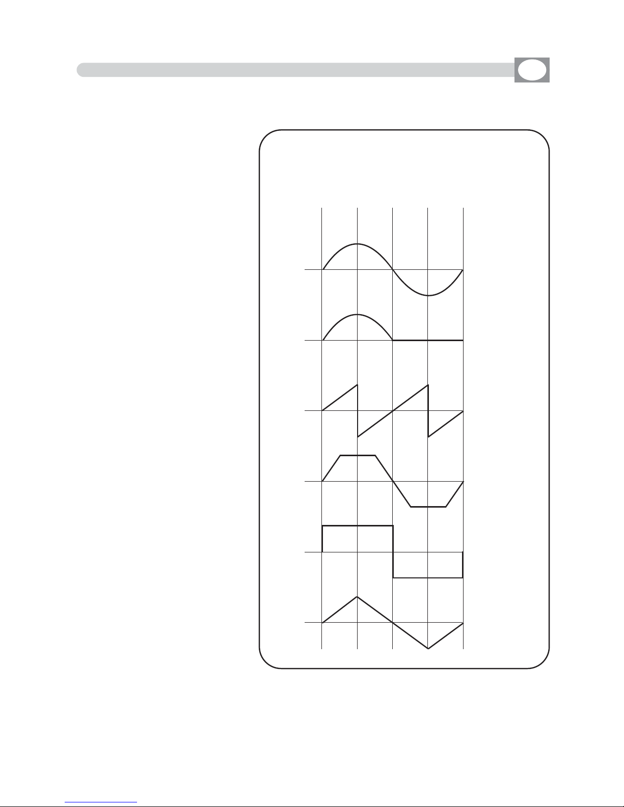
SHAPE
key
:
Press this key to select the
shapes, that are:
Circle, Hola, Ladder, Square,
Vertex, and Zigzag.
The parameters that the
operator could change correspond to:
SIZE
key
:
Press this key to change the
size of the shape (from 1 to
128)
RPM
key
:
Press this key to change the
speed and direction of the
shape (from -60 to +60)
PHASE
key
:
Press this key to change the
the start corner of the shape
(from 0 to 359).
DELAY
key
:
Press this key to change the
delay of the shape between
an unit and the next
(from 0
to 359).
0
Circle
Hola
Ladder
Square
Vertex
Zigzag
0
0
0
0
0
900 180 270 360
Wave’ s forms of the SHAPE

8.2 MASTER A + B USE
8.1 MANUAL PRESET FUNCTION
GB
MATRIX LIVE IS ENDOWED OF TWO CONTROL A+B LEVEL OUTPUT
The
MMaasstteerr AA
fader
(Fig. 38)
allows to adjust the bright
of preset A
The
MMaasstteerr BB
fader
(Fig. 38)
allows to adjust the bright
of preset B
The
MMaasstteerr BB
fader has the scale inverted as regards
the
MMaasstteerr AA
fader,
move the two knobs at the same
time to have a AAand
BB
mix.
12 bank A faders to control presets A
12 bank B faders to control presets B
12 keys: perform flash on the channels.
12 led: Visualize the channels status.
BANK key:
(Fig. 37) to select the preset page, max 12.
Press
BBaannkk
key followed from 1÷12 key, to change page
Press
twice
the
BBaannkk
key to go to the next page
TThhee sseelleeccttiioonn ooff tthhee bbaannkk iiss lliimmiitteedd ttoo tthhee nnuummbbeerr ooff tthhee ddiimmmmeerr
sseett iinn tthhee ppaattcchh..
Led display:
(Fig. 37) Visualize the active preset page.
THIS SECTION OF MATRIX LIVE IS MANUAL ENTIRELY CONTROLLED
10
9
8
7
6
5
4
3
2
1
0
0
1
2
3
4
5
6
7
8
9
10
B
A
A B
AA aanndd BB
Key are used to enable the two presets crossfa-
de, for this function keep
oonnee
master to 0 value (the corresponding led will turn off).
Set the transition
XXFFAADDEE TTIIMMEE
from 0 to 600
seconds with encoder under lcd display
Press Function key then AAor
BB
key to cange lcd
XXFFAADDEE TTIIMMEE
of manual presetPress Function key then AAo
Bank
0 1
Fig. 37
Fig. 38

8.4 FUNCTION KEYS IN REGISTER MODE
GB
In REGISTER mode there are 6
ffuunnccttiioonn kkeeyyss
see (Fig. 40 par
88..33
)
EDIT
key
:
Press this key to create/modify the active register, the display changes as
shown in
(Fig. 42 par
88..55
)
NAME
key
:
Press this key to modify register name.
Through the encoder choose the character, Through the OK or
CHAR
Key we insert/modify
the next/precedent character. Press
DONE
key to confirm the modify of the name.
BANK
key
:
Press this keys to select the successive/precedent page
KEY
key
:
Press this key to change register function
GO-PAUSE = Pause/Go register
FLASH 100% = Play the register at 100% up to the key isn’t left (with cursor to zero too)
FLASH GO = Play the register up to the key isn’t left
TAP KEY = Change the register step by step
MODE
key
:
Press this key to cange register function fader
ONCE = Register play once and stop it
SOLO = Only one register in output the others has excluded.
ONCE + SOLO = Only one register in output the others has excluded, register play once and stop it

RREEGG
BB AA CC KK EE RR AA SSEE PP RR OO GG CCHH AA SS EE EE FFFFEECCTT DD OONN EE
0022
BBKKGGRR PPRROOGG
0011
CCHHAASS
0011
EEFFFFTT
0022
RREEGG 000011
0011..0011
8.5 EDIT IN REGISTER MODE
GB
The graphic display indicates the step (
hhiigghhlliigghhtteedd
) currently active
(Fig. 40 par
88..33
)
to create/modify it press the
EDIT
key (Fig. 41).
The display changes as shown in (Fig. 42).
THIS FUNCTION ALLOWS TO CREATE OR MODIFY
ONE OF 144 REGISTER.
For successive register use the
PAGE or BANK
key
Fig. 42
BBPPCCEE
RREEGG 000077
0011..0077
RREEGG 000088
0011..0088
RREEGG 000099
0011..0099
RREEGG 001100
0011..1100
RREEGG 001111
0011..1111
RREEGG 001122
0011..1122
RREEGG 000022
0011..0022
BBPPCCEE
RREEGG 000033
0011..0033
RREEGG 000044
0011..0044
RREEGG 000055
0011..0055
RREEGG 000066
0011..0066
Function Keys
see par 8.6
indicate number
and register page
shows the active
register 002
shows the register
contained
Background
Program
Chase
Effect
Return to the precedent function
Key to erase the
Background scene
Key to erase/modify programm
chase and effect
Key to confirm
Fig. 41
EE DD II TT

8.6 FUNCTION KEYS IN EDIT REGISTER
GB
In REGISTER mode there are 6
ffuunnccttiioonn kkeeyyss
see (Fig. 42 par
88..55
)
BACK
key
:
Press this key to return to the precedent
functionn see par
88..22
ERASE
key
:
Press this key to the erase Background scene
PROG
key
:
Pessing this key it becomes
NONE
key and appears the encoder symbol, now
you can change program, presse
NONE
key to delete from the register.
CHASE
key
:
Pessing this key it becomes
NONE
key and appears the encoder symbol, now
you can change chase, presse
NONE
key to delete from the register.
EFFECT
key
:
Pessing this key it becomes
NONE
key and appears the encoder symbol, now
you can change effect, presse
NONE
key to delete from the register.
DONE
key
:
Premendo questo tasto si confermano le modifiche effettuate.

8.7 REGISTRER SECTION
GB
12 faders: controls the live playback registers.
Mode:
Once, Solo e Once + Solo
(see par
88..44
)
12 keys: perform direct registers functions.
Mode:
Go-Pause, Flash 100%, Flash Go e Tap Key
(see par
88..44
)
12 bicolor led : Shows the register status.
Green Switched on: Register in play
Green Blinking: Register in pause
Red Switched on: Register in play in other page
Red Blinking: Register in pause in other page
TIME fader: to control stepping in real time.
Press TIME key then the register you wants to perform in step mode. Use the fader from 0
to 100% and viceversa to change the step in real time.
Keep the register fader to 100%
Press TIME key to go out of the functionn.
GRAB key: grab the active scene (bakground) into a register.
Press GRAB key then the register you wants to store the scene
BANK key: to select registers page max 12
Press
BBaannkk
key then the register 1÷12 key to cange page
Press twice
BBaannkk
key to go in the next page
Led display: visualize registers active page.
Lcd: visualizes registers job mode.
FUNCTION key: to set lcd functions
Press Function key then AAor
BB
key to cange
XXFFAADDEE TTIIMMEE
of manual preset
Press Function key then
RReeggiisstteerr
1/12 key to cange
RREEGG SSPPEEEEDD
of single register
Press Function key then
RReeggiisstteerr
1/12 key
aanndd hhoollddiinngg tthhee RReeggiisstteerr kkeeyy,, sseelleecctt ootthheerr rreeggii--
sstteerr
to cange
RREEGG SSPPEEEEDD
of those register
Press twice Function key to cange in
MMAAIINN SSPPEEEEDD
Encoder: to set lcd values.
THE REGISTER SECTION IS THE “HEART” OF MATRIX LIVE.

A
PPrrooggrraamm
is a range of scenes (max 48) performed in succession.
To create/modify a program follow all steps listed below:
1) If Matrix is switched off, switch it on pressing
POWER
key.
2) Press Program key to activate the
PROGRAM
function.
(the Program led key will light up).
3) Press 1÷12 keys to select only the program that you want to modify.
(only one program
hhiigghhlliigghhtteedd
).
For successive program use the
PPAAGGEE
key
4) Press the UNITS key and select through the 1÷12 keys the units that must
work in the program. Confirm with the DONE key
5) Press Scene key to activate the
SCENE
function.
(the Scene led key will light up).
6)
Press one of the 1÷12 keys to select the scene that we want to create/modify
.
For successive scenes use the
PPAAGGEE
key
7) Press the EDIT key to create/modify the selected scene.
8) Modify the position with the joystick and the sets of the channels with the
relative faders, press
UNIT
key for
next/precedent
unit.
9) When the scene has been completed, it can be stored through the SAVE key.
11)
Now
Matrix
is in the next scene
repeat again the 7 and 8 steps.
12)
When
the creation of the scenes has been finished press Program key to
come back to the
PROGRAM
function.
(the Program led key will light up).
13) Finally you must press the LIVE key followed to GO key to execute the program.
The program is complete; to create/modify others repeat again all the above
steps.
9.1 CREATION OF A PROGRAM
GB

A
CChhaassee
is a play of lights, it is a sequence of steps (from 1 to 48 max).
To create/modify a program follow all steps listed below:
1) If Matrix is switched off, switch it on pressing
POWER
key.
2) Press Chase key to activate the
CHASE
function.
(the Chase led key will light up).
3) Press 1÷12 keys to select only the chase that you want to modify.
(only one chase
hhiigghhlliigghhtteedd
).
For successive chase use the
PPAAGGEE
key
4) Press STEPS key to activate the STEPS function
5)
Press one of the 1÷12 keys to select the step that we want to create/modify
.
For successive
steps
use the
PPAAGGEE
key
7 Press the EDIT key to create/modify the selected
step
.
9)
Modify the value of the channels through the 12 relative faders or the 1÷12 keys.
For next channels use the
PPAAGGEE
key
10) When the step is completed
it can be stored through the SAVE key.
11)
Now
Matrix
is in the next step
repeat again the 9 and 10 steps
.
12)
When
the creation of the steps has been finished press Chase key to
come back to the
CHASE
function.
(the Chase led key will light up).
13) Finally you must press the LIVE key followed to GO key to execute the
chase.
The chase is complete; to create/modify others repeat again all the above
steps.
9.2 CREATION OF A CHASE
GB

Matrix is endowed with pre-programmed plays movement, (modifiable) dedicated to the scanner and moving-head.
With this function it’s possible to create animations of notable effect.
The available plays are:
Circle, Hola, Ladder, Square, Vertex, and Zigzag.
The parameters that the operator could vary correspond to:
SHAPE:
Shape
SIZE:
Dimension of the shape (from 1 to 128)
RPM:
Speed and direction of the shape ( from -60 to +60)
PHASE:
Corner of departure of the shape (from 0 to 359).
DELAY:
Delay of execution of the shape between an unit and the next (from 0 to 359).
The parameters are independent for
PAN
and
TILT,
it is possible an infinity of
combinations.
1)If Matrix is switched off, switch it on pressing
POWER
key.
2) Press Effect key to activate the
EFFECT GENERATOR
function.
(the Effect led key will light up).
3)
Press one of the 1÷12 keys to select the effect that we want to create/modify
.
For successive
effect
use the
PPAAGGEE
key
4) Press the EDIT key to create/modify the selected
effect
.
5) Press one of the 1÷6 keys to select the effect on the
PAN
channel
Press one of the 7÷12 keys to select the effect on the
TILT
channel
6) Modify the parameters of the effect through the
SHAPE , SIZE, RPM,
PHASE and DELAY
keys
.
7) Once modified the parameters, we can be store the modifications through
the SAVE key.
8)
Now
Matrix
is again in the
EFFECT
function
.
9) Press the
UNITS
key to check which unit must perform the effect.
10) Finally you must press the LIVE key followed to GO key to execute the effect.
The effect is complete; to create/modify others repeat again all the above
steps.
9.3 CREATION OF AN EFFECT
GB

10.1 MENU FUNCTION
10.2 MENU: BLACKOUT
GB
Press
Menu
key to activate
MENU
function.
(Fig. 45)
The display changes as shown in
(Fig. 46)
As soon as this function is activated, the display shows the
first function available..
Through the encoder it is possible select the
MENU
functions available.
To activate the selected function press the same (OK) key.
THIS FUNCTION ACTIVATES SOME SPECIAL FUNCTIONS FOR THE CONTROL OF THE
UNIT AND THE SETTING OF THE CONTROLLER.
Fig. 45
MAIN MENU
BBLLAACCKKOOUUTT
LLAAMMPP OONN -- OOFFFF
RREESSEETT UUNNIITTSS
FFAADDEERRSS FFUUNNCCTTIIOONN
EEDDIITT DDMMXX PPAATTCCHH
SSYYSSTTEEMM SSEETTTTIINNGGSS
OK
Menu
Fig. 46
---------------------------------------------------------------------------------------------------------------------
AVAILABLE ONLY AFTER THE ACTIVATION OF THE MENU FUNCTIONS (see par.10.1)
---------------------------------------------------------------------------------------------------------------------
This function allows to black-out all the unit connected.
Press
DONE
or
ESC
key to start again the normal working.
The display changes as shown in
(Fig. 46).
Pressing the KEEP key the Blackout comes kept up to when you call a program or a scene.
BB AA CC KK DD OONN EE
BB LLAA CC KK OO UU TT
!
Fig. 46
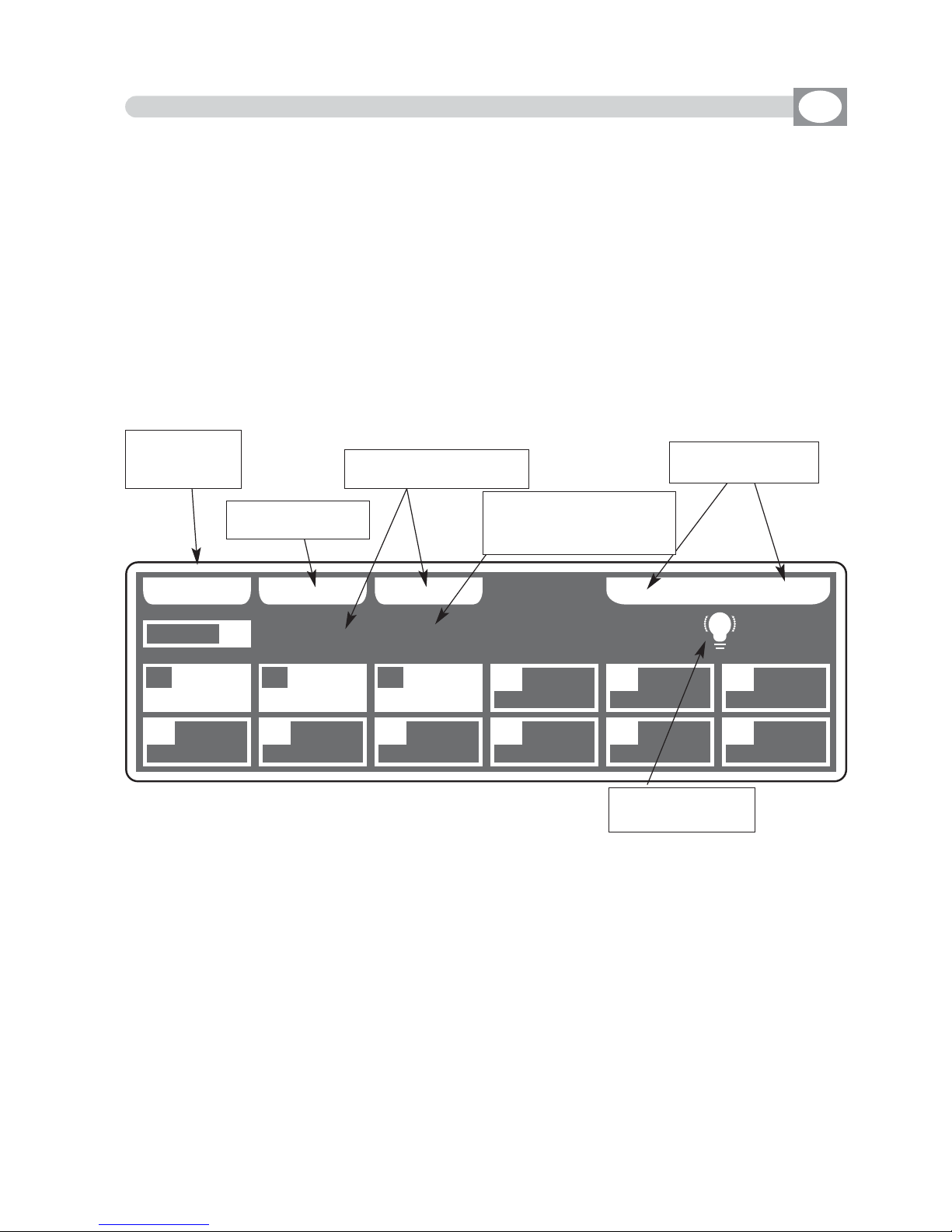
10.3 MENU: LAMP ON - LAMP OFF
---------------------------------------------------------------------------------------------------------------------
AVAILABLE ONLY AFTER THE ACTIVATION OF THE MENU FUNCTIONS (see par.10.1)
---------------------------------------------------------------------------------------------------------------------
ALLOWS TO TURN ON / TURN OFF THE LAMP OF ONE OR MORE UNIT.
(only if the selected unit are predisposed for this function).
NOTE: If the lamp is “discharge” type and it is still hot, before its lighting you will
need to wait that it gets cold.
The display changes as shown in
(Fig. 47).
At the activation of the function the units are all selected.
Press one of the 1÷12 keys to select the unit.
For successive unit use the
PPAAGGEE
key
ALL
key
:
Press this key to select all the
unit
from 1 to 48.
SOLO
key
:
Press this key to select only the unit shown in the box
UUNNIITT
, if we have selected
with the
AALLLL
key all the
4488
unit, and we wants to selectd only the unit (es. n°
0022),,
press twice the key
0022
of unit selection. The unit box will indicate
UUNNIITT 0022
now
the
SOLO
key unselect all the other unit, activating
SOLO
the
UUNNIITT 0022
OFF - ON
keys
:
Pressing one of these two keys will be turn on/turn off the lamp of the selected unit.
To get out of the function press the
EESSCC
key.
GB
BB AA CC KK AA LL LL SS OOLLOO
** ** 00 33 UU NN II TT SS ** **
RROOBBOOCCOOLL II
MMAARR
UUNNIITT
0011
0011 0022 0033 0044 0055 0066
0077 0088 0099 1100 1111 1122
OO FFFF LLAA MM PP OO NN
XXMM11220000 3300
DDTTSS CCPP
SSUUPPEERR SSCCAA
Fig. 47
Appears at the
imparted command
Key for select only the
unit shown on
UUNNIITT
Shows name of the unit,
if are more of one it
Shows “
NNNN UUNNIITTSS””
Key for turn on/off
the lamp
Return to the
precedent
function
Key for select all
the unit

10.4 MENU: RESET UNITS
---------------------------------------------------------------------------------------------------------------------
AVAILABLE ONLY AFTER THE ACTIVATION OF THE MENU FUNCTIONS (see par.10.1)
---------------------------------------------------------------------------------------------------------------------
ALLOWS TO RESET ONE OR MORE UNIT.
(only if the selected unit are predisposed for this function).
This function must be performed when the unit lose synchronization or they
don’t perform the commands of the controller in a correct way.
The display changes as shown in
(Fig. 48).
At the activation of the function the units are all selected.
Press one of the 1÷12 keys to select the unit.
For successive unit use the
PPAAGGEE
key
ALL
key
:
Press this key to select all the
unit
from 1 to 48.
SOLO
key
:
Press this key to select only the unit shown in the box
UUNNIITT
, if we have selected
with the
AALLLL
key all the
4488
unit, and we wants to selectd only the unit (es. n°
0022),,
press twice the key
0022
of unit selection. The unit box will indicate
UUNNIITT 0022
now
the
SOLO
key unselect all the other unit, activating
SOLO
the
UUNNIITT 0022
RESET
key
:
Press this key to reset the selected
unit
To get out of the function press the
EESSCC
key.
GB
Fig. 48
BB AA CC KK AA LL LL SS OOLLOO
MM AARR RR OO BB OO CC OO LLOO RR II II XX
RROOBBOOCCOOLL II
MMAARR CCPP
XXMM11220000 3300 SSUUPPEERR SSCCAA
DDTTSS
RR EESS EETT !!
UUNNIITT
0011
00220011 0033 0044 0055 0066
0077 0088 0099 1100 1111 1122
Key for select all
the unit
Key for select only the
unit shown on
UUNNIITT
Shows name of the unit,
if are more of one it
Shows “
NNNN UUNNIITTSS””
Key for reset the units
Return to the
precedent
function

DD OONN EE
RREEDD GGRREEEENN BBLLUUEE **FFRREEEE** **FFRREEEE** **FFRREEEE**
BB
LL II VVEE
EEDDIITT UUNNIITT FFUUNNCCTTIIOONN......
10.5 MENU: FADERS FUNCTIONS
---------------------------------------------------------------------------------------------------------------------
AVAILABLE ONLY AFTER THE ACTIVATION OF THE MENU FUNCTIONS (see par.10.1)
---------------------------------------------------------------------------------------------------------------------
ALLOWS TO ASSIGN THE NAME OF THE DMX CHANNEL TO DETERMINED FADERS
THIS FUNCTION IS VALID IN THE MODE OF OPERATION EDIT SCENE (SEE
PAR 4.5) AND MANUAL (SEE PAR 4.10)
This function is used when we have the need to control a determined channel (of all the connected units), always and only from a faders.
The display changes as shown in (Fig. 49).
When yuo keep the fader to zero value the display shows the writing
**ffrreeee**
, free
from assignments, the channels come loaded from the controller in an original way.
Move the fader of the section "A" or " B," to assign a memorized channel.
Through the encoder or the 1/12 keys directly above at the faders you can roll
forward/back for a more precise search.
To assign the channel press the
DONE orOK
key
To get out of the function press the
EESSCC
key.
Fig. 49
Shows the 33faders of the
AA
section
Indicate that the channel
can be modified with the
encoder
Shows the 33faders of the
BB
section
Key to confirm
Key to assign the
channel in live way
see par 10.6
GB

DD OONN EE
DDMMXX110000 MMAAIINN SSPPDD PPRROOGG SSPPDD **FFRREEEE** **FFRREEEE** **FFRREEEE**
**FFRREEEE** **FFRREEEE** **FFRREEEE** **FFRREEEE** **FFRREEEE** **FFRREEEE**
BB
EEDDIITT UUNNIITT FFUUNNCCTTIIOONN......
10.6
MENU: FADERS FUNCTIONS LIVE
---------------------------------------------------------------------------------------------------------------------
AVAILABLE ONLY AFTER THE ACTIVATION OF THE MENU FUNCTIONS (see par.10.1)
---------------------------------------------------------------------------------------------------------------------
ALLOWS TO ASSIGN DIRECT CONTROL FUNCTIONS AT 12 FADERS.
This function is used to control the performance of programs, chase, effects through
faders or to control a determined DMX channel.
The display changes as shown in
(Fig. 50).
The functions that the operator could assign through the relative keys correspond to:
MAIN SPD :
Performance Speed of the
Show
PROG SPD:
Performance Speed of the
Program
CHAS SPD:
Performance Speed of the
Chase
EFT SPD:
Performance Speed of the
Effect
EFT ZOOM:
Dimension of the
Effect
DMX 001:
Direct control of the channel
FREE:
No function associate
If the function is of
DMX
type, through the faders or the encoder you select the channel.
Except
MMAAIINN SSPPDD
the other functions could join to specific registers through the cursor
or the encoder
To assign the function faders press the
DONE orOK
key
To get out of the function press the
EESSCC
key.
NOTE: THIS FUNCTION IS ACTIVE IN MODE:
SCENE/STEPS/PROG/GO! PROG/CHASE/GO! CHASE/EFFECT/GO! EFFECT/SHOW/GO! SHOW
FOR RECALL THE DISPLAY THAT SHOWS THE VALUES, PRESS THE CORRESPONDING Show, Effect, Chase, Program KEY (FIXED LED)
Fig. 50
Shows the 33faders immediately under the display
Key to confirm
GB
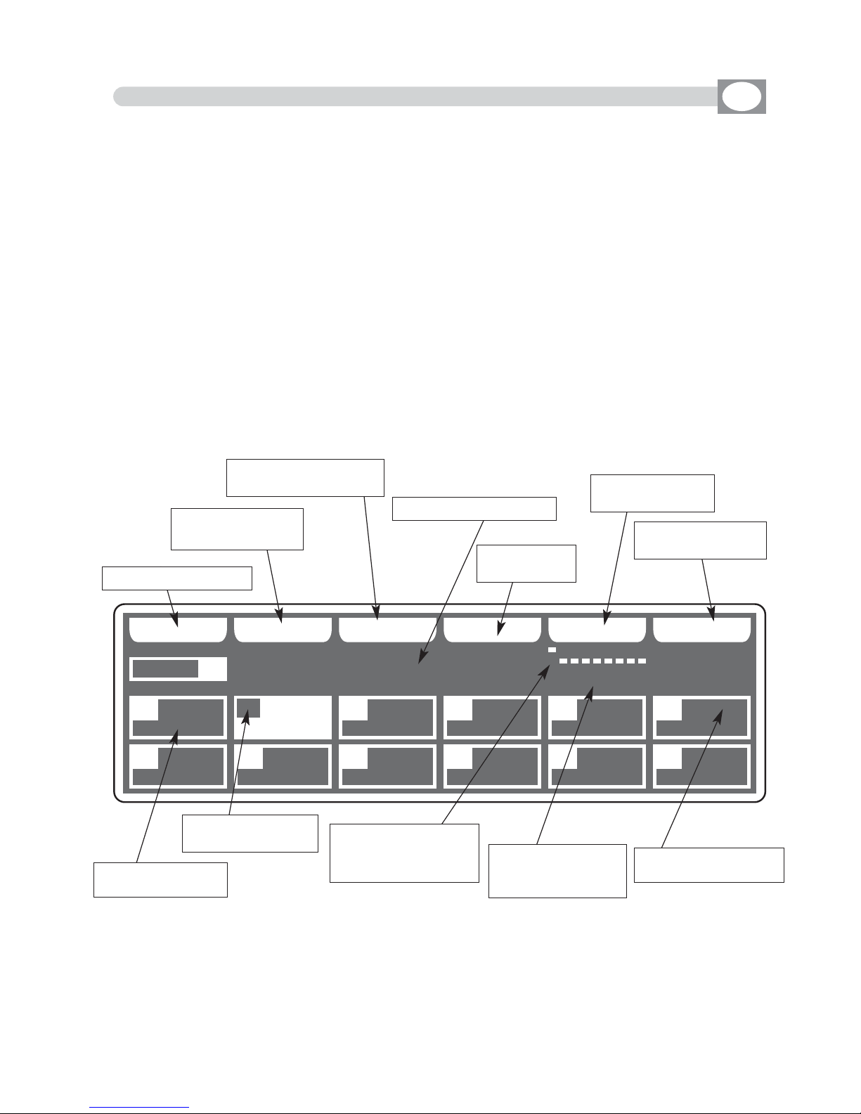
UUNNIITT
CC OO PP YY LL OO AA DD EE DD II TT EE RR AA SS EE PP AA TT CC HH
SSGG MM GG II OO TT TT OO WW .. 44 00 00
RROOBBOOCCOOLL II
MMAARR CCPP
GGIIOOTTTTOO WW.. SSUUPPEERR SSCCAA
SSGGMM
AA UU TTOO !!
0022
0022
0011 0033 0044 0055 0066
0077 0088 0099 1100 1111 1122
CCHH 000011..000066
10.7 MENU: EDIT DMX PATCH
---------------------------------------------------------------------------------------------------------------------
AVAILABLE ONLY AFTER THE ACTIVATION OF THE MENU FUNCTIONS (see par.10.1)
---------------------------------------------------------------------------------------------------------------------
ALLOWS TO LOAD A COMPLETE SETUP FROM LIBRARY AND STORE IT IN MEMORY.
ALLOWS TO PATCH DMX / AUTOMATIC / MANUAL.
ALLOWS TO MODIFY THE NAME OF EACH CHANNEL AND ITS PARAMETERS
(RESET VALUE, BLACKOUT VALUE, HARD/SOFT CROSS) IT ALSO ALLOWS TO ASSIGN SPECIAL FUNCTIONS TO THE CHANNEL (PAN/TILT,PAN LOW/TILT LOW,
LAMP CONTROL).
ATTENTION ! MODIFICATION OF THE
EDIT DMX PATCH
PARAMETERS, IF NOT
EFFECTED IN AN APPROPRIATE WAY, PREVENTS THE CONNECTED UNIT TO WORK
CORRECTLY.
The display changes as shown in (Fig. 51).
Press one of the 1÷12 keys to select the unit.
For successive unit use the
PPAAGGEE
key
Fig. 51
GB
Key to copy the unit
Key to load setup
from library
Key to modify the parameters of the unit
Key to erase
the unit
Shows name of the unit
Key to manual
patch
Key to automatic
patch
Shows short name
of the unit
Shows the configuration to set on the [dipswitch] of the unit.
Shows the start and
end channel of the
unit.
Shows the number
of the unit
Empty box, no unit
loaded

10.8 FUNCTION KEYS IN EDIT DMX PATCH MODE
GB
In EDIT DMX PATCH mode there are 6
ffuunnccttiioonn kkeeyyss
see (
Fig. 51 par
1100..77
).
COPY
Key
:
Pressing this key on the display shows
"" SSEELLEECCTT DDEESSTTIINNAATTIIOONN UUNNIITT"",,
select through the
1÷12 keys the destination of the copy.
For the successive unit use
PPAAGGEE
key
LOAD
Key
:
Press this key to load compleate setup from library,
see
par
1100..99
.
EDIT
Key
:
Press this key
to modify the name of each channel and its parameters
,
see
par
1100..1111
.
ERASE
Key
:
Press this key to the erase active unit, select through the 1÷12 keys (for the successive
units use
PPAAGGEE
key) the unit that must be erased, then press the
EERRAASSEE
key.
The unit will erased in a permanent way, it is not possible recover it.
PATCH
Key
:
Press this key to modify start address of the unit, use the fader under
PATCH
write or
the encoder. To confirm the modify press the
OOKK
key, to get out of the function press
the
EESSCC
key
.
Matrix will calculate the last channel for that unit and under
PATCH
write you can shows
the configuration to set on the dip-switch of the unit.
NOTE: ANY BUILDERS ADOPT THE CONFIGURATION OF THE DIP-SWITCH LIKE
STANDARD SET TO "0" FOR INDICATE DMX CHANNEL "1." IN THIS CASE FOR A
CORRECT OPERATION, YOU MUST BE ADDED +1" (EXAMPLE ADDRESS OF
UNIT START = 128 ---> MATRIX ADDRESS = 129
The on position of the dip-switch is with white box appears aloft.
When you exit from the menù the software controls if there are unit with equal or overlapped addresses, the display shows a message of error "PATCH OVERLAY AT UNIT."
AUTO
Key
:
Press this key to modify start address in automatic way, select through the 1÷12 keys
the unit of start , then press the
AUTO
key.
For the successive unit use
PPAAGGEE
key
Now from the unit of start to the last unit the addresses have been assigned.
For the successive unit use
PPAAGGEE
key

UUNNIITT
LL OO AA DDBB AA CC KK
CCPP
GGIIOOTTTTOO WW.. SSUUPPEERR SSCCAA
SSGGMM
0044
0022
RROOBBOOCCOOLL II
MMAARR
0011 00440033 0055 0066
0077 0088 0099 1100 1111 1122
AA BB SS CCLLUU BB CC OO LLOO RR
AA÷ZZ
10.9 LOAD LIBRARY IN EDIT DMX PATCH MODE
10.10 FUNCTION KEYS IN LOAD LIBRARY MODE
GB
Press the
LOAD
key to load setup from library (Fig. 52).
The display changes as shown in (Fig. 53).
The display shows the first unit in the library
ALLOWS TO LOAD A COMPLETE SETUP FROM LIBRARY AND STORE IT IN MEMORY.
Fig. 52
LL OO AA DD
Fig. 53
Key to confirm
Keys to search in alphabetical sequence inside
of the memory
Shows name of the unit
Indicate the
number of unit
Shows short name of
the unit previously loaded from internal
library see par.
10.6
Shows where will come loaded the unit
---------------------------------------------------------------------------------------------------------------------
AVAILABLE ONLY AFTER THE ACTIVATION OF THE MENU FUNCTIONS (see par.10.7)
---------------------------------------------------------------------------------------------------------------------
In
LOAD LIBRARY
mode there are 3
ffuunnccttiioonn kkeeyyss
see
(Fig. 53)
A ÷ Z
Key
:
Press this key to search in alphabetical sequence inside of the memory, when
youn arrive at the initial letter of the firm, you can search through the encoder
in fine way. For a rapid search could be used also the faders under
LOAD
write
LOAD
Key
:
Press this key to load the select unit in the box
highlighted
.
To get out of the function press the
EESSCC
key
.
Return to the precedent function

Fig. 55
CC HH AA RR
BB AA CC KK DD OONN EE
UUNNIITT
NN AA MM EEBB AA CC KK
0022
SSGG MM GG II OO TT TT OO WW .. 44 00 00
PPAANN
CCHH0011
PPAANN LLOOWW
CCHH0022
TTIILLTT
CCHH0033
TTIILLTT LLOOWW
CCHH0044
CCOOLLOOUURR
CCHH0055
CCYYAANN
CCHH0066
MMAAGGEENNTTAA
CCHH0077
YYEELLLLOOWW
CCHH0088
DDIIMMMMEERR
BB BB BB
CCHH0099
SSHHUUTT//SSTTRR
CCHH1100
ZZOOOOMM
CCHH1111
MM--SSPPEEEEDD
CCHH1122
10.11 EDIT IN EDIT DMX PATCH MODE
GB
The graphic display indicates the unit (
hhiigghhlliigghhtteedd
) currently active (Fig.
51 par
1100..77
)
to modify it press the
EDIT
key (Fig. 54).
The display changes as shown in (Fig. 56).
Pressing the
NAME
key it is possible modify the name of the
projector, the display changes as shown in (Fig. 55).
Through the encoder we select the character, with the
OK
key or the
CHAR
keys we
modify the next/precedent character. Press
DONE
key to confirm the modify of the
name.
ALLOWS TO MODIFY THE NAME OF EACH CHANNEL AND ITS PARAMETERS
(RESET VALUE, BLACKOUT VALUE, HARD/SOFT CROSS) IT ALSO
ALLOWS TO ASSIGN SPECIAL FUNCTIONS TO THE CHANNEL
(PAN/TILT,PAN LOW/TILT LOW, LAMP CONTROL).
Fig. 54
EE DD II TT
Fig. 56
Key to modify the name
of the unit
Key to return to the menù
function see par 10.7
Indicate the number of the channel
Shows name of the
channel
Shows that the channel
is hard cross
Shows that the channel
is soft cross
Shows that the channel
have a blackout value
with
BB..
a reset value
with
RR..
a blackout and
reset value with
BBRR..
---------------------------------------------------------------------------------------------------------------------
AVAILABLE ONLY AFTER THE ACTIVATION OF THE MENU FUNCTIONS (see par.10.7)
---------------------------------------------------------------------------------------------------------------------

Through the 1÷12 keys select the number of the channel to modify see (Fig. 56 par
1100..1111
).
For the successive
channels
use
PPAAGGEE
key
The selected channel will come highlighted the display changes as shown in (Fig. 57).
To use
Function Keys
see par
1100..1133
The controller uses these special channels for predefined functions, you must use them for
the specific functions assigned to them.
NOT USED -> Not used channel.
PAN -> Pan channel (SOFT CROSS/HARD CROSS).
PAN LOW -> Pan channel LOW.
TILT -> Tilt channel (SOFT CROSS/HARD CROSS).
TILT LOW -> Tilt channel LOW.
LAMP -> Lamp control channel.
LAMP/RES -> Like LAMP.
UUNNIITT
NN AA MM EE
SSOO FFTT XX
HH AA RR DD
XX
BB LLKK OO UU TT
RR EESS EETTBB AA CC KK
0022
DD II MMMM EERR 0000 00
SSOOFFTT
CCRROOSSSS
== == ==
PPAANN
CCHH0011
PPAANN LLOOWW
CCHH0022
TTIILLTT
CCHH0033
TTIILLTT LLOOWW
CCHH0044
CCOOLLOOUURR
CCHH0055
CCYYAANN
CCHH0066
MMAAGGEENNTTAA
CCHH0077
YYEELLLLOOWW
CCHH0088
DDIIMMMMEERR
BB
BB BB
CCHH0099
SSHHUUTT//SSTTRR
CCHH1100
ZZOOOOMM
CCHH1111
MM--SSPPEEEEDD
CCHH1122
Fig. 57
Shows the
blackout value
Shows the
reset value
Shows name of the
channel
Shows that the channel
is hard cross
Shows that the channel
is soft cross
Shows that the channel
have a blackout value
with
BB..
a reset value
with
RR..
a blackout and
reset value with
BBRR..
Key to modify the name
of the channel
Key to set the channel
like soft cross
Key to set the channel
like hard cross
Key to set a blackout value
Key to set a reset value
Key to return to the precedent
function see par 10.11
10.12 EDIT OF DMX CHANNELS
GB
---------------------------------------------------------------------------------------------------------------------
AVAILABLE ONLY AFTER THE ACTIVATION OF THE MENU FUNCTIONS (see par.10.11)
---------------------------------------------------------------------------------------------------------------------

10.13 FUNCTION KEYS IN EDIT OF DMX CHANNELS MODE
GB
In EDIT DMX CHANNEL mode there are 6
ffuunnccttiioonn kkeeyyss
see (Fig. 57 par
1100..1122
).
BACK
Key
:
Press this key to return to the precedent function see par
1100..1111
NAME
Key
:
Press this key to replace the channel name.
Use the fader under
NAME
write or the encoder. To confirm the modify press the
NAME
or OKkey.
Putting the faders to 0 value *CUSTOM* appears on the display, now we can write the name of the channel.
Pressing again
NAME
key the display changes as shown in (Fig. 58).
Through the encoder choose the character, Through the OK or
CHAR
Key we insert/modify the next/precedent character.
Press
DONE
key to confirm the modify of the name.
The value change between two scenes can be immediate
(HARD CROSS) or gradual (SOFT CROSS).
SOFT X
Key
:
Press this key to set for the selected channel the type of gradual change (SOFT CROSS).
HARD X
Key
:
Press this key to set for the selected channel the type of immediate change (HARD CROSS)
BLKOUT
Key
:
Press this key to modify “BLACKOUT VALUE” that is the value of the channel when the BLACKOUT func-
tion is active ( see par.10.2).
Through the encoder or the fader under the
BLKOUT
write, you can select === (unchanged) value or 0 /
255 value. The === value is selected putting the fader to 0 and it allows to maintain unchanged the output
value (no blackout for this channel).
RESET
Key
:
Press this key to modify “RESET VALUE” that is the value of the channel when the MENU: RESET function
is active (see par.10.4).
Through the encoder or the fader under the
RESET
write, you can select === (unchanged) value or 0 /
255 value. The === value is selected putting the slider to 0 and it allows to maintain unchanged the output value (no reset for this channel).
Only if the LAMP or LAMP/RES channel is selected you can modify the
LAMP ON /LAMP OFF value. see (Fig. 59).
L-ON
Key
:
Press this key to modify “LAMP ON VALUE” that is the value of the
channel when the MENU: LAMP ON function is active (see par.10.3).
Through the encoder or the fader under the
L-ON
write, you can select
0 / 255 value.
L-OFF
Key
:
Press this key to modify “LAMP OFF VALUE” that is the value of the channel when the MENU: LAMP OFF
function is active (see par.10.3).
Through the encoder or the fader under the
L-OFF
write, you can select 0 / 255 value.
DDOO NNEE
Fig. 58
CC HH AA RR
LL --OONN LL -- OOFF FF
Fig. 59
show the lamp
on/off value
LL--OONN 114400
LL--OOFFFF 000000

10.14 MENU: SYSTEM SETTINGS
GB
Select
SYSTEM SETTINGS
from main menù the display changes as shown in (Fig. 60)
As soon as this function is activated, the display shows the first function available.
Through the encoder it is possible select the
SYSTEM SETTINGS
functions available.
To activate the selected function press the same (OK) key.
ALLOWS TO CHANGE THE DISPLAY CONTRAST, TO SET A PASSWORD, RS 232
FUNCTIONS, SHOW THE SOFTWARE VERSION.
Fig. 60
---------------------------------------------------------------------------------------------------------------------
AVAILABLE ONLY AFTER THE ACTIVATION OF THE MENU FUNCTIONS
(see par.10.1)
---------------------------------------------------------------------------------------------------------------------
SYSTEM SETTINGS
SSEETT LLCCDD CCOONNTTRRAASSTT
SSEECCUURRIITTYY LLOOCCKK
RRSS 223322 HHOOSSTT LLIINNKK
AABBOOUUTT MMAATTRRIIXX
WWII--DDMMXX TTRRAANNSSMMIITTTTEERR
AABBOOUUTT MMAATTRRIIXX
SYSTEM SETTINGS
SSEETT LLCCDD CCOONNTTRRAASSTT
SSEECCUURRIITTYY LLOOCCKK
RRSS 223322 HHOOSSTT LLIINNKK
AABBOOUUTT MMAATTRRIIXX
WWII--DDMMXX TTRRAANNSSMMIITTTTEERR
AABBOOUUTT MMAATTRRIIXX
10.15 MENU: SET LCD CONTRAST
---------------------------------------------------------------------------------------------------------------------
DISPONIBILE SOLO DOPO L’ATTIVAZIONE DELLA FUNZIONE SYSTEM SETTINGS (see par.10.14)
---------------------------------------------------------------------------------------------------------------------
THIS FUNCTION ALLOWS TO CHANGE THE GRAPHIC DISPLAY CONTRAST
The display changes as shown in (Fig. 61)
Through the encoder or the fader under the
DONE
write, you can modify the
display contrast
. To confirm the modify press the
OOKK
key, to get out of the func-
tion press the
EESSCC
key.
DD OONN EE
Fig. 61

N
ext
MATRIX live v. 1.0
LIB 48 CH v 1.1.3
29/02/08 AT16MSPI
Fig. 63
MATRIX
live
10.16 MENU: SECURITY LOCK
GB
ALLOWS TO LOCK/UNLOCK FUNCTIONS OF EDITING AND RESETTING.
Pressing the
LOCK
key
(F6)
the display will change as shown in (Fig. 62)
Through the 1÷10 keys, insert a numerical combination of 5 number for lock the functions.
At the end of the last number MATRIX will ask “ENTER PASSWORD AGAIN”, you must
introduce the password again. Now MATRIX is locked.
To unlock it repeat again all the above steps list above, but you must remember the password.
If you forget the password, we have a code of unblocking that is:
F6 1 3 9 7 F2
MATRIX TOTAL RESET :
With MATRIX unlocked, do this sequence of keys:
F6 10 8 2 4 F4,
then follow the display instructions .
---------------------------------------------------------------------------------------------------------------------
AVAILABLE ONLY AFTER THE ACTIVATION OF THE SYSTEM SETTINGS
(see par.10.14)
---------------------------------------------------------------------------------------------------------------------
SECURITY LOCK
**** MMAATTRRIIXX IISS UUNNLLOOCCKKEEDD ****
EENNTTEERR PPAASSSSWWOORRDD::
..........
LL OO CC KK
Fig. 62
10.17 MENU: ABOUT MATRIX
GB
---------------------------------------------------------------------------------------------------------------------
AVAILABLE ONLY AFTER THE ACTIVATION OF THE SYSTEM SETTINGS
(see par.10.14)
---------------------------------------------------------------------------------------------------------------------
ALLOWS TO SHOW THE SOFTWARE VERSION.
The display changes as shown in (Fig. 63)
Model
Library Date
Library Version
Software Version
Brand
F1
F2
F3 F4 F5 F6

10.18 MENU: RS 232 HOST LINK
GB
---------------------------------------------------------------------------------------------------------------------
AVAILABLE ONLY AFTER THE ACTIVATION OF THE SYSTEM SETTINGS
(see par.10.14)
---------------------------------------------------------------------------------------------------------------------
THIS FUNCTION ALLOWS TO UPDATE LIBRARY, SAVE THE PROGRAMMING AND TO
RESTORE USER DATA.
The display changes as shown in (Fig. 64)
RS232 HOST LINK
11.. CCOONNNNEECCTT RRSS223322 CCAABBLLEE
22.. OOPPEENN TTEERRMMIINNAALL AASS::
****111155220000--88--NN--11****
33.. PPRREESSSS SSTTAARRTT BBUUTTTTOONN
44.. FFOOLLLLOOWW IINNSSTTRRUUC
CTTIIOONNSS
SSTT AA RR TT
Connect the RS 232 cable (included)
from the Matrix to the RS 232 of the
Computer, start a program of terminal
emulation and to set the communication like:
115200 bps, 8 data bit, no parity, 1
stop bit.
With
MMiiiiccrroossoofftt WWiinnddoowwss
®®
system
start the software
HH yy ppeerr TTeerrmmiinnaall
(Start> Programs> Accessories>
Communications), set the connection
like in
ffiigg..6655--6666--6677
.
Press the
SSTTAARRTT
key (Matrix); in the
monitor of
Computer
appears the Menù
see
ffiigg..6688
.
Press (
CCoommppuutteerr KKeeyybbooaarrdd
) the number
of the desired function.
Press
11
to save the data of programming;
You must select from the menù
TTrraannssffeerr>> RReecceeiivvee ffiillee
. Set
YYmmooddeemm
protocol then click to
RReecceeiivvee
The
saved file is in the Hard Disk with
name
MMAATTRRIIXX..BBAAKK..
Fig. 65
Fig. 66

Fig. 68
Fig. 69
Press
22
to restor the data of programming;
You must select from the menù
TTrraannssffeerr>> SSeenndd ffiillee
. search the
file with
MMAATTRRIIXX..BBAAKK
name, set
YYmmooddeemm
protocol then click to
SSeenndd
.
Press 33to update setup library;
you must select from the file
menù
TTrraannssffeerr>> SSeenndd ffiillee
. search
the file with
MMaatt__lliibb..bbiinn
name
((ddoowwnnllooaaddeedd ffrroomm iinntteerrnneett))
, set
YYmmooddeemm
protocol then click to
SSeenndd
see
ffiigg..6699
.
Press
44
for personal library
backup;
You must select from the menu
TT rr aann ss ffee rr>> RR eeccee iivvee ffii ll ee
. Set
YYmmooddeemm
protocol then click on
RReecceeiivvee..
The file will be saved on computer hard drive with this name:
mmyylliibb..BBAAKK..
Press 55to exit.
Close the application and disconnect the cable.
Fig. 67

10.19 MENU: SD CARD ACCESS
---------------------------------------------------------------------------------------------------------------------
AVAILABLE ONLY AFTER THE ACTIVATION OF THE SYSTEM SETTINGS
(see par.10.14)
---------------------------------------------------------------------------------------------------------------------
ALLOWS TO UPDATE SOFTWARE,
LIBRARY, SAVE THE PROGRAMMING AND TO
RESTORE USER DATA.
The display changes as shown in (Fig. 70)
GB
SD CARD ACCESS
BBAACCKKUUPP UUSSEERR DDAATTAA
RREESSTTOORREE UUSSEERR DDAATTAA
UUPPDDAATTEE FFIIXXTTUURREE LLIIBBRRAARRYY
BBAACCKKUUPP PPEERRSSOONNAALL LLIIBBRRAARRYY
SSOOFFTTWWAARREE UUPPDDAATTEE
EERRAASSEE FFIILLEESS FFRROOMM CCA
ARRDD
DO NOT REMOVE THE CARD DURING READING AND WRITING OPERATIONS
BACKUP USER DATA
Press OK to save programming data, default is
MMAATTRRIIXX..BBAAKK
. Press
SSAAVVEE
to confirm.
Press
NNAAMMEE
to change the name, Through the encoder choose the character, Through
the OK or
CHAR
Key we insert/modify the next/precedent character. Press
SSAAVVEE
to
save programming data.
RESTORE USER DATA
Press OK to restore programming data.
Through the encoder choose saved file, press
LLOOAADD
to load the file.
UPDATE FIXTURE LIBRARY
Press OK to update fixture library.
Through the encoder choose the .
LLIIBB
file from Codem provided, press
LLOOAADD
to load the
file.
BACKUP PERSONAL LIBRARY
Press
OOKK
to save personal library, default is
MMYYLLIIBB..BBAAKK
. Press
SSAAVVEE
to confirm.
Press
NNAAMMEE
to change the name.
SOFTWARE UPDATE
Press OK to update the software.
Through the encoder choose the .
FFWWUU
file from Codem provided, press
LLOOAADD
to load
the file.
Do not turn off Matrix during this operation.
ERASE FILES FROM CARD
Press
OOKK
to delete card files.
Through the encoder choose the file, press
EERRAASSEE
to erase.
Fig. 70

10.20 MENU: WI-DMX TRANSMITTER
---------------------------------------------------------------------------------------------------------------------
AVAILABLE ONLY AFTER THE ACTIVATION OF THE SYSTEM SETTINGS
(see par.10.14)
---------------------------------------------------------------------------------------------------------------------
ALLOWS TO PAIR WI D PEN RECEIVER, CHANGE THE RADIO CHANNEL AND TO
SELECT OF WIRELESS CONTROLLED UNITS
.
the display will change as shown in (Fig. 70)
GB
WI-DMX TRANSMITTER
SSEETT NNEEWW CCHHAANNNNEELL
SSEENNDD RRAADDIIOO PPAAIIRRIINNGG
SSEELLEECCTT WWIIRREELLEESSSS UUNNIITTSS
PAIRING:
1) Power up
WWii DD PPeenn
receiver
2) Hold the button until the
WWii DD PPeenn
led starts blinking red/green alternately
3) In Matrix Live through the encoder find
SSEENNDD RRAADDIIOO PPAAIIRRIINNGG
4) Press
OOKK
key and wait the
DDOONNEE
message
5) The
WWii DD PPeenn
receiver is paired
TO CHANGE RADIO CHANNEL:
1) Power up
WWii DD PPeenn
receiver
2) In Matrix Live through the encoder find
SSEETT NNEEWW CCHHAANNNNEELL
3) Press
OOKK
key and wait the
DDOONNEE
message
4) The
WWii DD PPeenn
receiver has change radio channel and led’s colour
SELECTION OF WIRELESS CONTROLLED UNITS:
1) Through the knob find the writing
SSEELLEECCTT WWIIRREELLEESSSS UUNNIITT
2) Confirm with the
OOKK
key
3) Select the units that will work in wireless and confirm with the
DDOONNEE
key
Fig. 70

10.21 MENU: MIDI
GB
NOT ENABLE IN SOFTWARE

MATRIX LIVE TECHNICAL FEATURES
• Individual control of up to 36 DMX 512 units.
• 48 DMX channels for each unit.
• 512 DMX configurable channels for intelligent units and dimmers.
• 48 Program processor with 48 scenes each one (2304 total scenes).
• 36 Chase processor with 48 scenes each one (1728 total scenes).
• 48 Built in editable Effects.
• 144 Registrs with 1 Progam + 1 Chase + 1 Effect + 1 Preset.
• 2 bank of 12 faders to control 144 Dimmer channels.
• RS-232 for connection with a PC.
• DMX 512/1990 standard output (5-pole female “XLR” connector).
• SD CARD slot for data backup.
• MIDI IN/TRHU/OUT.
• Built-in Wireless Wi DMX®transmitter.
• GRAPHIC white led backlight LCD PANEL.
• Very easy SETUP with wide LIBRARY, allows the configuration of each unit connected to
the Matrix live.
• Control of the 48 channels by 12 faders for simplest use.
• Compatible with every DMX 512 unit (max 48 channels)
• 8/16 bit PAN and TILT movements controlled by an auto-return Joystick.
• MUSIC function with indipendent speed.
• Built-in microphone and 0 dB audio input with auto-level control.
• Non volatile 16 Mbit FLASH memory with 40 years data retention.
• Very simple programming and intuitive use.
Condizioni climatiche di utilizzo:
• Umidità: 35% ÷ 80%
• Temperatura: -10° ÷ +50 °C
Dimensioni e peso:
Dimensioni (L x H x P) / Peso: 712 x 436 x 55 mm 15 Kg.

CODEM MUSIC S.r.l. - Via G.Pierini, 13 - 61100 PESARO - ITALY
Tel. +39 0721 204357 - Fax +39 0721 203554
http://www.codemmusic.com - E-mail: info@codemmusic.com
All rights reserved. No parts of this document can be copied, photocopied or reproduced without the
prior written permission of the CODEM MUSIC s.r.l.
No responibility is taken for possible inaccuracies or mistakes.
The CODEM MUSIC s.r.l. reserves the right to make any alterations or aesthetics changes of this
product that seem necessary at any time and for whatever reason.
The CODEM MUSIC s.r.l. takes no responsibility for the use or for the application of this product.
GB
 Loading...