

Page 1
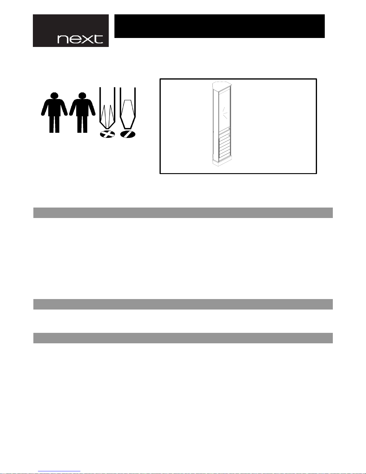
Tools Needed
Helpline
If you have any problems with this product or
require any replacement fittings please contact
Customer Services Tel: 0844 844 8999
• Made from MDF with painted finish & mirrored glass doors.
• For general cleaning, periodically dust with a soft cloth.
CARE INSTRUCTIONS
ASSEMBLY INSTRUCTIONS.
Regrettably self assembly items cannot be returned once assembly is part or fully completed unless the item is found
to be faulty. Should you need to return the unassembled product, please repack in the original packaging.
IMPORTANT
• Avoid keeping furniture in direct sunlight or close to any heat sources as this can cause cracking, discolouration or
warping.
• Do not rub or scrub the surface when cleaning.
• Made in China.
IMPORTANT - RETAIN FOR FUTURE REFERENCE - READ CAREFULLY.
• Keep fittings out of children's reach and keep children well away from the construction area.
• Carefully check that you have all parts before beginning assembly.
• Wall fixings must be used for stability on this item and for safety reason the cabinet should be left freestanding.
• We recommend that the packaging is used to protect the surfaces during assembly.
• A minimum of 2 persons is required to assemble this product.
• All assembly fixings should always be tightened properly and periodically check all fixings and tighten if necessary.
• The maximum load this cabinet shelves can hold is 5 kg.
• We would recommend that the following methods to be used to hang the cabinet. NB - Screws & Raw plugs for
the wall are not included.
PRODUCT INFORMATION
• We suggest you spend a short time reading through this leaflet and then follow the simple step-by-step instructions.
• Always use a non-silicone based furniture polish. Silicone in furniture polishes can break down the lacquer finish.
• Any spills should be removed immediately with a soft clean damp cloth and dried immediately.
• Never drag pieces of furniture across the floor as this will cause damage to the joints.
850018 SOUTHPORT CORNER TALLBOY
Page 1 of 7
Page 2
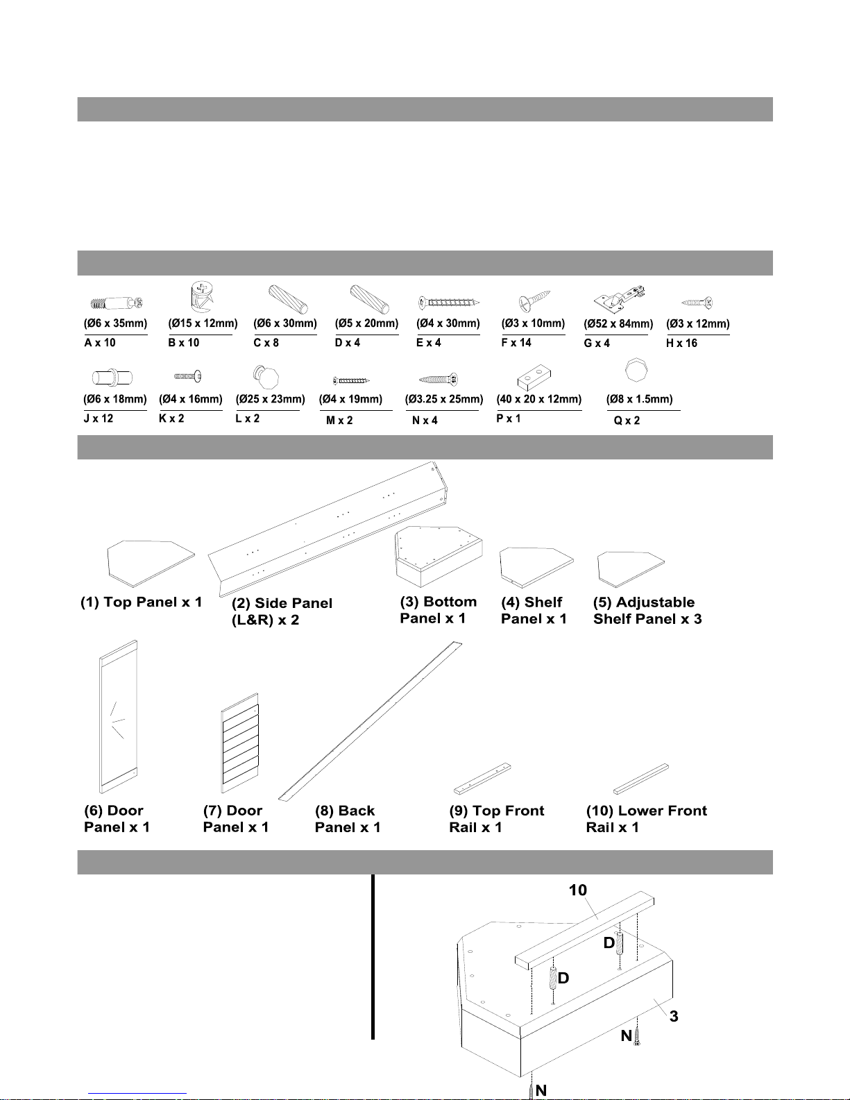
1. Insert 2 x wooden dowels (D) into bottom
panel 3.
2. Attach lower front rail 10 to bottom panel 3
with 2 x screws (N) and tighten.
GLASS INFORMATION
• Clean using a glass cleaner and soft cloth. Do not use cleaning products containing abrasives as these will scratch
the glass.
• This item contains mirror glass. Please handle with extreme care.
• Batch No.04/2013
• This product contains 3mm mirror glass that does not conform to BS 6206. If the mirror glass is chipped or broken
replace with glass of the type described. Consult the manufacturer, retailer or agent with regard to obtaining a
manufacturing specification and shape for replacement mirror glass quoting the model number and batch number or
date of manufacture.
PARTS
STEP ONE
FITTINGS
• BS 7449: 1991.
Page 2 of 7
Page 3
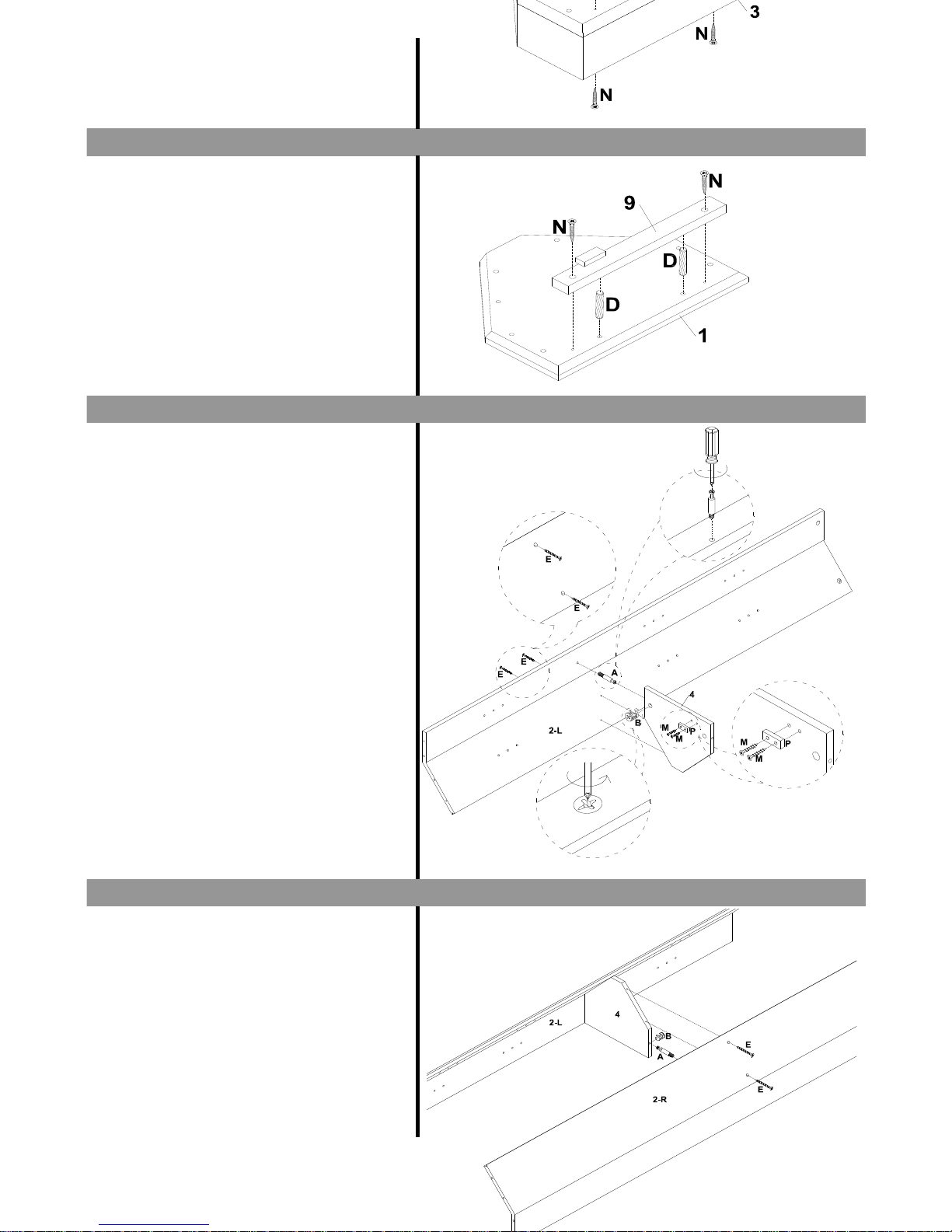
1. Insert 2 x wooden dowels (D) into top panel 1.
2. Attach top front rail 9 to top panel 1 with 2 x
screws (N) and tighten.
1. Attach 1 x wooden stopper (P) to shelf panel 4
with 2 x screws (M), tighten with a screwdriver.
2. Insert 1 x cambolt (A) into side panel 2-L.
3. Attach shelf panel 4 to side panel 2-L with 2 x
screws (E) and tighten.
4. Insert 1 x camlock (B) into shelf panel 4.
Ensure the arrow indicator is pointing towards
the panel edge before tightening with a
screwdriver.
1. Insert 1 x cambolt (A) into side panel 2-R.
2. Attach side panel 2-L to the assembled unit
with 2 x screw (E).
3. Insert 1 x camlock (B) into shelf panel 4.
Ensure the arrow indicator is pointing towards
the panel edge before tightening with a
screwdriver.
STEP FOUR
STEP THREE
STEP TWO
Page 3 of 7
Page 4
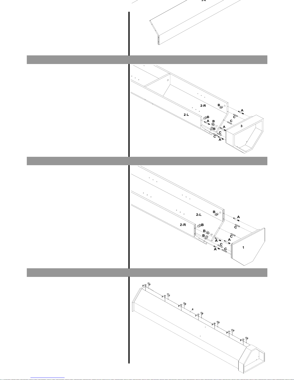
1. Insert 4 x cambolts (A) and 4 x wooden dowels
(C) to bottom panel 3.
2. Attach bottom panel 3 to the assembled unit
with.
3. Insert 4 x camlocks (B) to side panel 2 (both
L&R). Ensure the arrow indicator is pointing
towards the panel edge before tightening with a
screwdriver.
1. Insert 4 x cambolts (A) and 4 x wooden dowels
(C) in to top panel 1.
2. Attach top panel 1 to the assembled unit.
3. Insert 4 x camlocks (B) into side panel 2 (both
L&R). Ensure the arrow indicator is pointing
towards the panel edge before tightening with a
screwdriver.
1. Attach back panel 8 to the assembled unit with
14 x screws (F) and tighten.
STEP SIX
STEP FIVE
STEP SEVEN
Page 4 of 7
Page 5
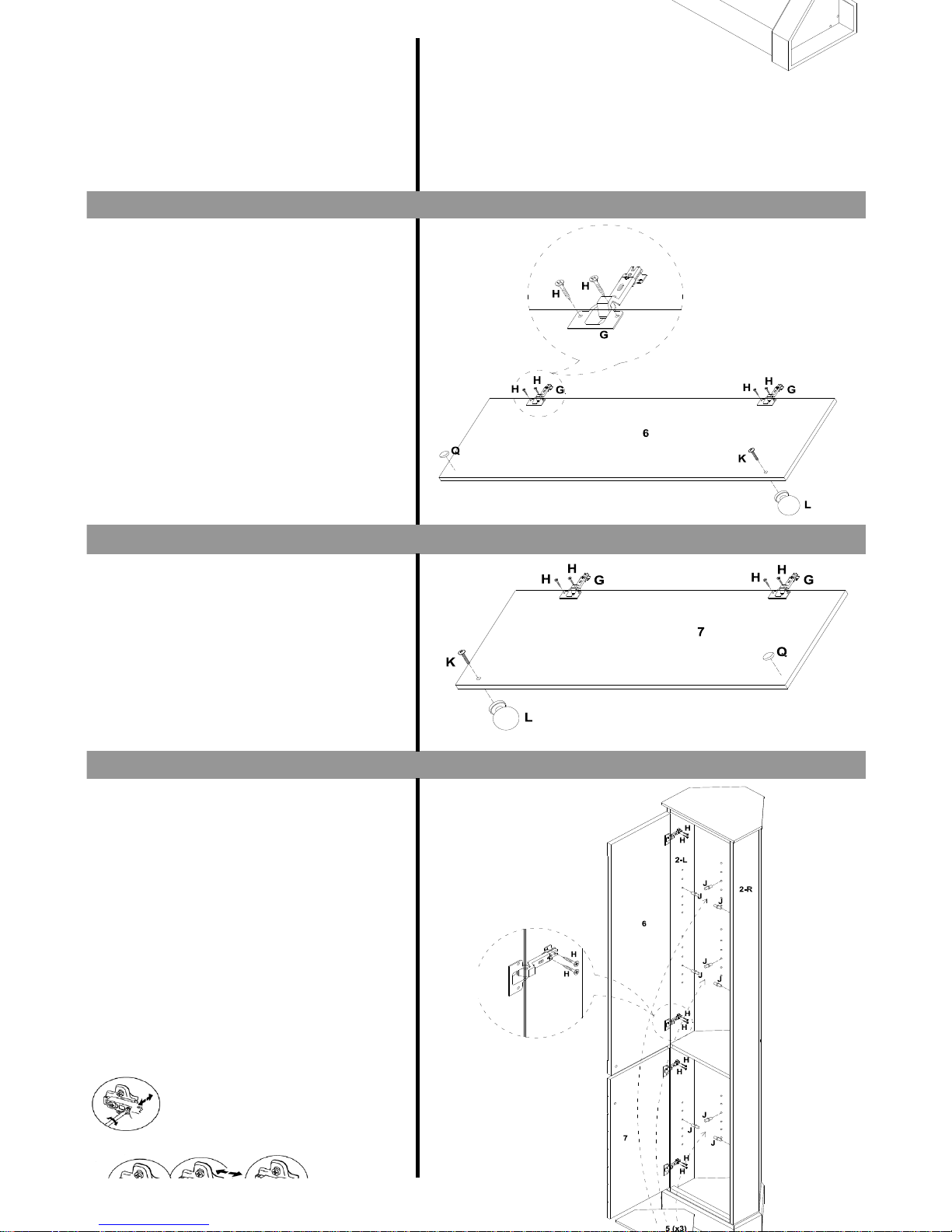
1. Attach 2 x hinges (G) to door panel 6 with 4 x
screws (H) and tighten.
2. Attach 1 x handle (L) to door panel 6 with 1 x
bolt (K) and tighten.
3. Attach 1 x rubber pad (Q) to door panel 6.
1. Attach 2 x hinges (G) to door panel 7 with 4 x
screws (H) and tighten.
2. Attach 1 x handle (L) to door panel 7 with 1 x
bolt (K) and tighten.
3. Attach 1 x rubber pad (Q) to door panel 7.
1. Attach door panel 6 and door panel 7 to the
assembled unit with 8 x screws (H) and tighten
with a screwdriver.
2. Insert 12 x shelf supports (J) to the assembled
unit. Ensure that the four supports for shelf are
all at the same height. Note that the shelf
position is adjustable.
3. Place the adjustable shelf panels 5 (x3) onto
the shelf supports (J).
Note: The gaps between the door and frame can
be changed by making adjustments to the hinges
with a screwdriver. Refer to adjustment
diagrams.
Laterally (Side to Side)
Front to back
STEP NINE
STEP EIGHT
STEP TEN
Page 5 of 7
Page 6
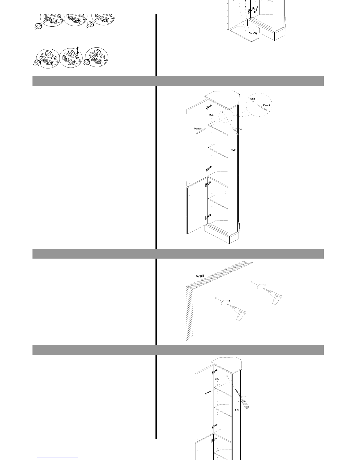
Vertically ( up and down)
1. Use pencil to mark through predrilled hole on
side panel.
1. Use power tool drill through the pencil mark.
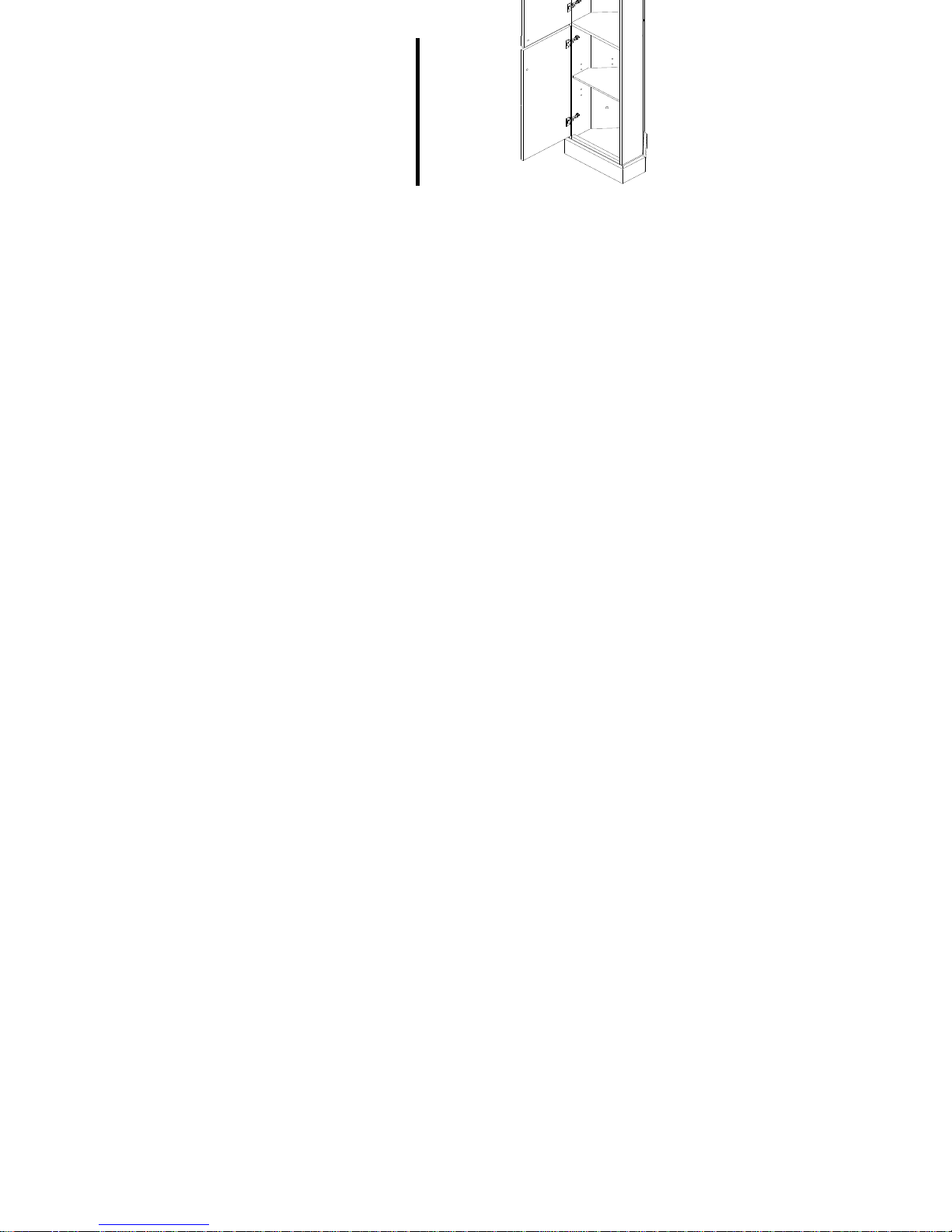
1. Attach the assembled unit to the wall with 4 x
screws, tighten with a screwdriver.
Warning : Always ensure the area to be drilled is
free from hidden electrical wires, water and gas
pipes.
NB : Wall fixings are not incuded, please source
suitable fixings for your wall type. If in doubt
please consult a qualified trades person.
STEP THIRTEEN
STEP ELEVEN
STEP TWELVE
Page 6 of 7
Page 7
Next Retail Ltd, Desford Road, Leicester, LE19 4AT
Page 7 of 7
 Loading...