

Page 1
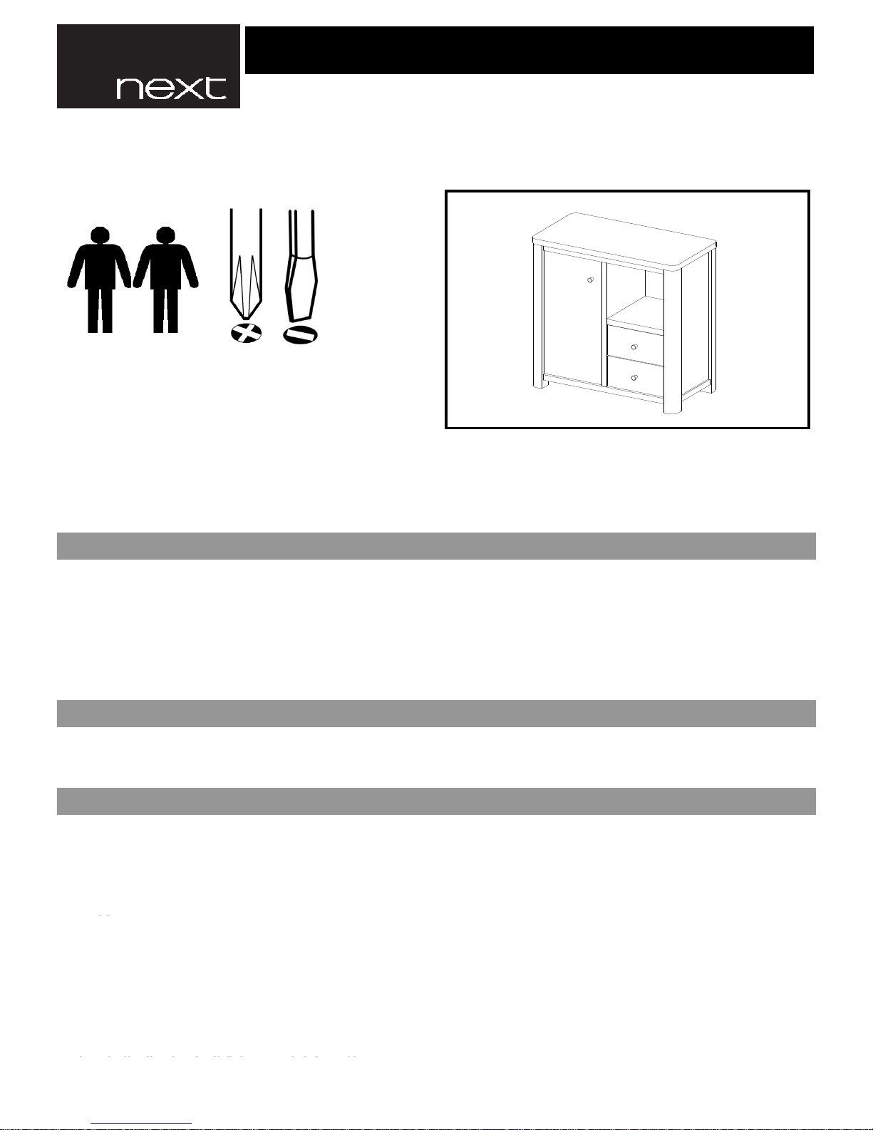
Tools Needed
Helpline
If you have any problems with this product or require
any replacement fittings please contact Customer
Services Tel: 0844 844 8999
or damage.
warping.
• All assembly fixings should always be tightened properly
• We recommend that the packaging is used to protect the surfaces during assembly.
• A minimum of 2 persons is required to assemble this product.
ASSEMBLY INSTRUCTIONS.
IMPORTANT - RETAIN FOR FUTURE REFERENCE - READ CAREFULLY.
Regrettably self assembly items cannot be returned once assembly is part or fully completed unless the item is found
to be faulty. Should you need to return the unassembled product, please repack in the original packaging.
IMPORTANT
• We suggest you spend a short time reading through this leaflet and then follow the simple step-by-step instructions.
• Carefully check that you have all parts before beginning assembly.
• Keep fittings out of children's reach and keep children well away from the construction area.
• Ensure the product is protected with mats and coasters when items are placed on the surfaces, to prevent
• Ensure the mats and coasters used do not have an abrasive surface underneath.
PRODUCT INFORMATION
• Made from particleboard,MDF with a wood effect finish.
• Made in Indonesia.
CARE INSTRUCTIONS
• For general cleaning, periodically dust with a soft cloth.
• Do not rub or scrub the surface when cleaning.
• Any spills should be removed immediately with a soft clean damp cloth and dried immediately.
• Do not put hot dishes directly on the surfaces of the item.
• Avoid keeping furniture in direct sunlight or close to any heat sources as this can cause cracking, discolouration or
• Never drag pieces of furniture across the floor as this will cause damage to the joints.
808953 BARLOW SMALL SIDEBOARD
1 of 12
Page 2
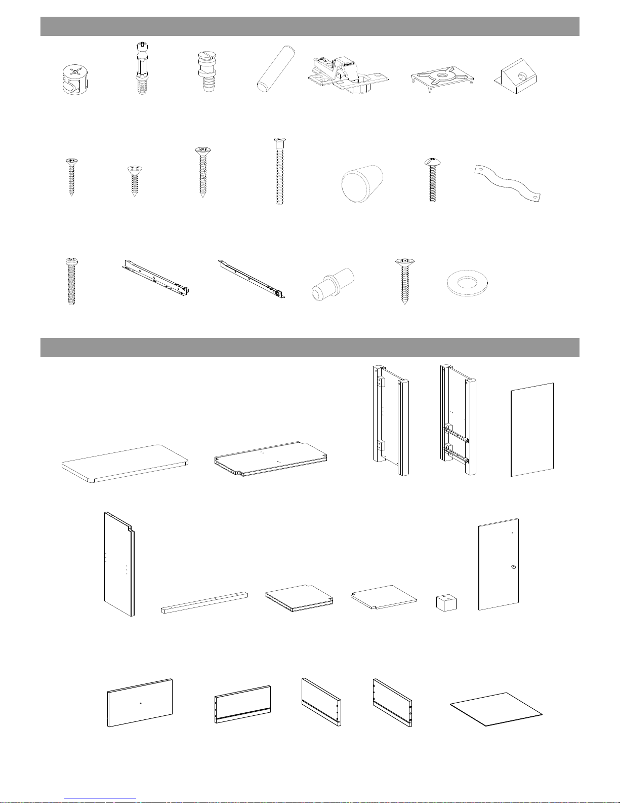
4x19 mm. F6x13 mm. F6x31 mm. F10x70 mm. 25x30 mm. P4x15 mm. 150 mm.
Hx14 Ix20 Jx4 Kx2 Lx3 Mx3 Nx1
Ox1 PLx2 PRx2 Qx4 Rx1 Sx1
15x12 mm. 7.5X32 mm. 20x9 mm. 8x32 mm. T26 Curve. 18x3 mm. 6x40 mm.
1x1 2x1 3Lx1 3Rx1 4x2
5x1 6x1 7x1 8x1 9x1 10x1
11x2 12x2 13Lx2 13Rx2 14x2
FITTINGS
Ax22 Bx22 Cx1 Dx33 Ex2 Fx2 Gx12
P6x30 mm. 350 mm. 350 mm. 15.3x25 mm. P6x19 mm. 4 mm.
PARTS
2 of 12
Page 3
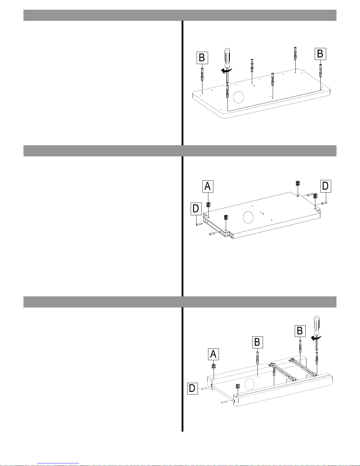
- Insert 6x cambolts (B) into the holes of panel 1 and tighten
with a cross blade screwdriver.
- Attach 4x camlocks (A) into the holes of panel 2 and
ensure that arrow indicator is pointing towards the panel
edge.
- Insert 4x wooden dowels (D) into the holes of panel 2.
- Attach 2x camlocks (A) into the holes of panel 3R and
ensure that arrow indicator is pointing towards the panel
edge.
- Insert 4x cambolts (B) and 2x wooden dowels (D) into the
holes of panel 3R.
STEP THREE
STEP TWO
STEP ONE
1
2
3R
3 of 12
Page 4
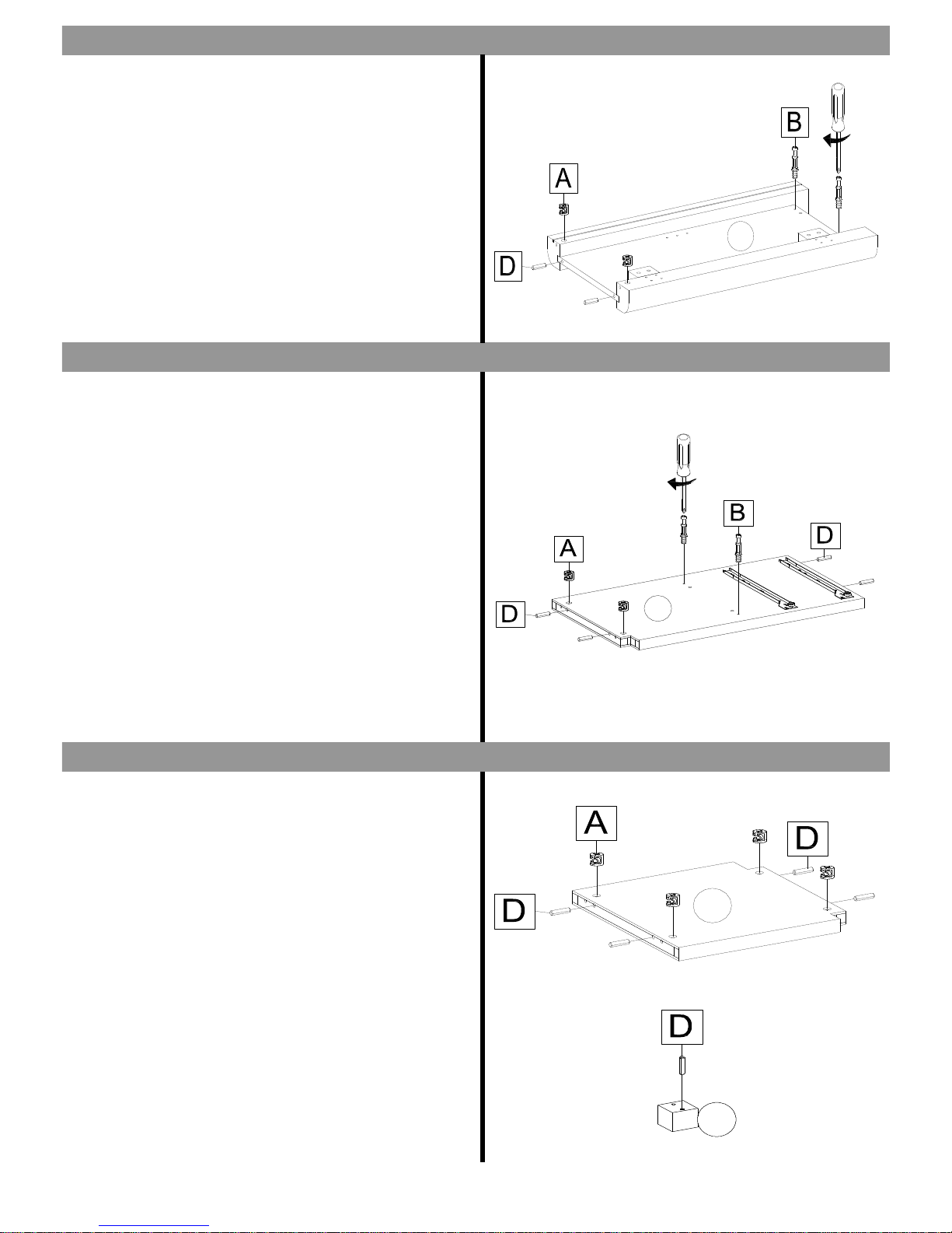
- Attach 2x camlocks (A) into the holes of panel 3L and
ensure that arrow indicator is pointing towards the panel
edge.
- Insert 2x cambolts (B) and 2x wooden dowels (D) into the
holes of panel 3L.
- Attach 2x camlocks (A) into the holes of panel 5 and
ensure that arrow indicator is pointing towards the panel
edge.
- Insert 2x cambolts (B) and 4x wooden dowels (D) into the
holes of panel 5.
- Attach 4x camlocks (A) into the holes of panel 7 and
ensure that arrow indicator is pointing towards the panel
edge.
- Insert 4x wooden dowels (D) into the holes of panel 7.
- Insert 1x wooden dowel (D) into the holes of panel 9.
STEP SIX
STEP FOUR
STEP FIVE
1
2
3R
3L
5
7
9
4 of 12
Page 5
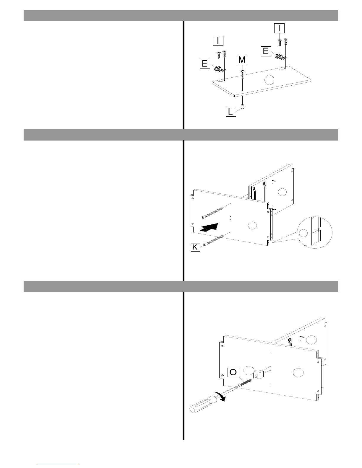
- Attach 2x hinges (E) to the holes of panel 10 and secure
by tightening 4x screws ( I ) clockwise with a cross blade
screwdriver.
- Attach 1x handle (L) to the holes of panel 10 and secure
by tightening 1x screw (M) clockwise with a cross blade
screwdriver.
- Attach panel 2 to the panel 5 by tightening 2x screws (K)
clockwise with a cross-blade screwdriver until tight.
(Tip - Ensure the groove on part 2 is positioned as shown)
- Attach panel 9 to the assembled unit by tightening 1x
screw (O) clockwise with a cross blade screwdriver.
STEP EIGHT
STEP SEVEN
STEP NINE
1
2
3R
3L
5
7
9
2
5
2
10
2
5
9
5 of 12
Page 6
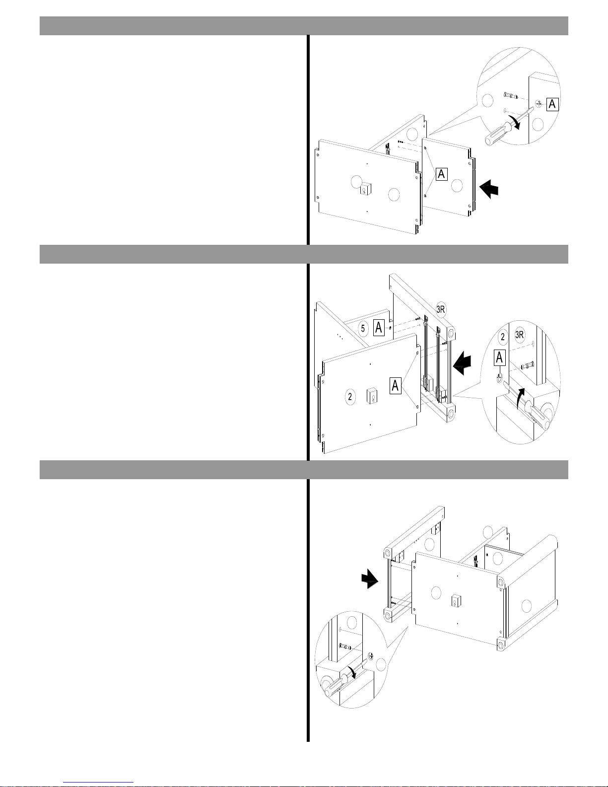
- Attach panel 7 to the assembled unit by tightening 2x
camlocks (A) clockwise with a flat-blade screwdriver.
- Attach panel 3R to the assembled unit by tightening 4x
camlocks (A) clockwise with a flat-blade screwdriver.
- Attach panel 3L to the assembled unit by tightening 2x
camlocks (A) clockwise with a flat-blade screwdriver.
STEP ELEVEN
STEP TEN
STEP TWELVE
1
2
3R
3L
5
7
9
2
5
2
5
9
2
7
5
7
3L
2
7
3L
2
5
3
6 of 12
Page 7
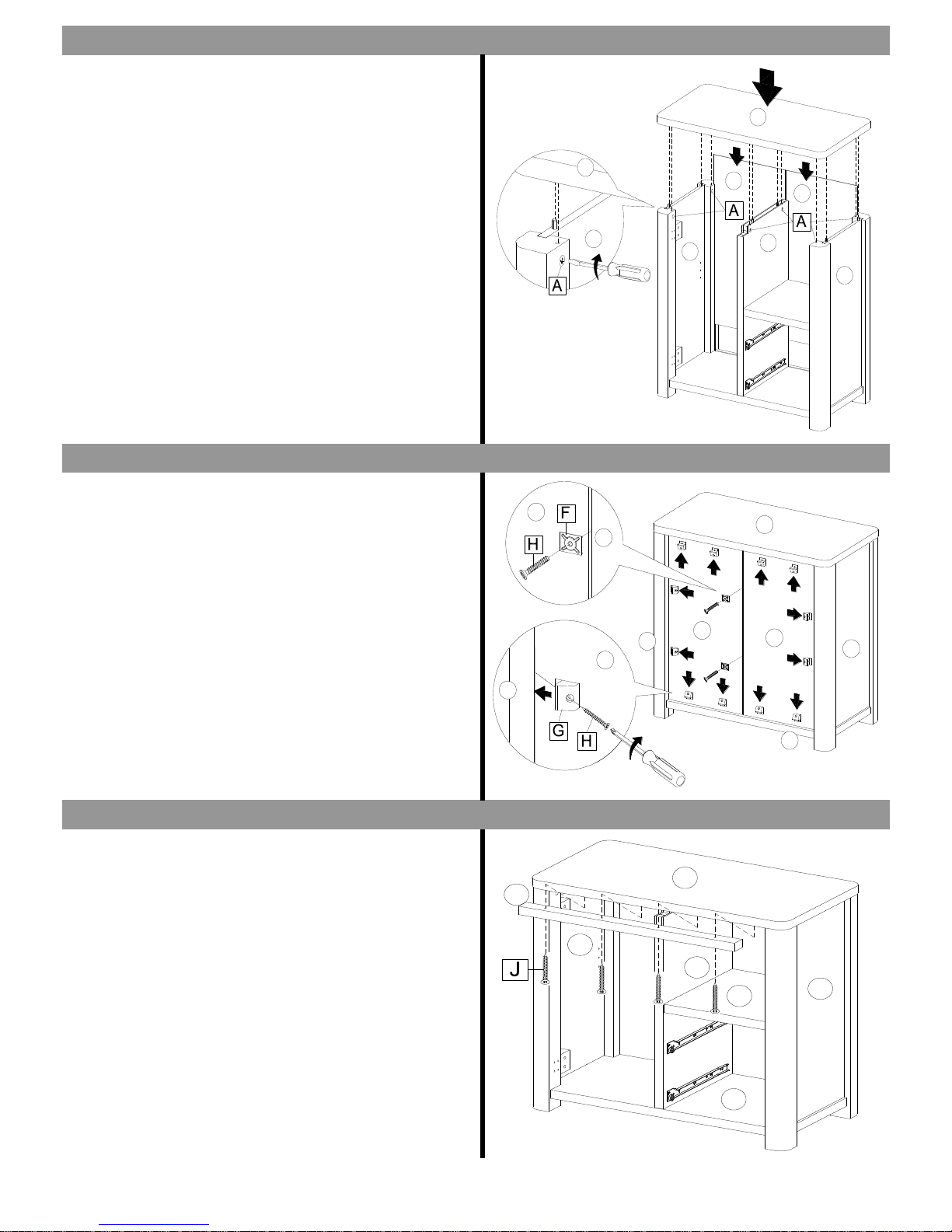
- Carefully lift the unit upright.This should be lifted by 2
people.
- Insert panel 4 (x2) to the recessed grooves of panel 3L,3R
and 2.
- Attach panel 1 to the assembled unit and tightening
6 x camlocks (A) clockwise with a flat-blade screwdriver.
- Attach 12x back board fasteners (G) to the backboard
grooves and secure by tightening 12x screws (H) clockwise
with a cross-blade screwdriver.
- Fix 2x metal brackets (F) to the centre of between panel 4
(x2)and tighten 2x screws (H) clockwise with a cross-blade
screwdriver.
- Attach panel 6 to the assembled unit by tightening
4x screws (J) clockwise with a cross-blade screwdriver.
STEP THIRTEEN
STEP FOURTEEN
STEP FIVETEEN
1
2
3R
3L
5
7
9
2
5
2
5
9
2
7
5
7
3L
2
7
3L
2
5
3
3L
3L
1
5
3R
1
4
4
4
4
2
3L
4
1
3R
3R
4
4
6
3R
7
2
3L
5
1
7 of 12
Page 8
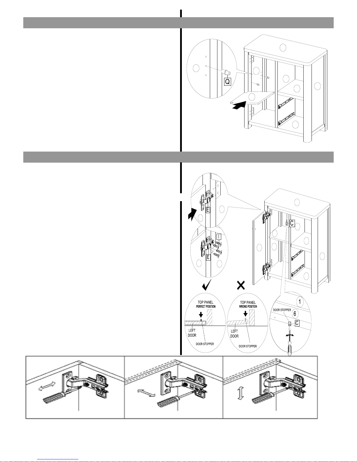
- Insert 4x shelf supports (Q) into the holes of panel 3L
and 5 and put panel 8 to the assembled unit.
- Insert 1x door stopper (C) into the hole of panel 6.
- Attach panel 10 to assembled unit and tighten 8 x
screws ( I ) clockwise with a cross-blade screwdriver until
tight.
(See the diagrams to set the hinges and door stopper.)
Lateral adjustment via screw Front-to back adjustment via screw on the hinge arm Vertical adjustment via two slots on mounting plate
STEP SIXTEEN
STEP SEVENTEEN
1
2
3R
3L
5
7
9
2
5
2
5
9
2
7
5
7
3L
2
7
3L
2
5
3
3L
3L
1
5
3R
1
4
4
4
4
2
3L
4
1
3R
3R
4
4
6
3R
7
2
3L
5
1
3L
2
8
3L
5
7
3R
1
10
3L
3L
10
10
2
3R
3L
8
7
5
1
8 of 12
Page 9
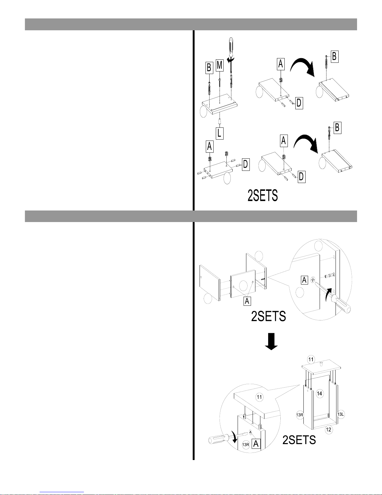
- Insert 4x cambolts (B) into the holes of panel 11(x2).
- Attach 2x handles (L) to the holes of panel 11(x2) and
tighten using 2x screw (M) clockwise with a screwdriver.
- Insert 4 x camlocks(A) to the hole of panel 13L (x2) and
13R (x2) and 8 x wooden dowels(D).
- Turn over panel 13L and 13R.
- Insert 4x cambolts (B) ) into the holes of panel 13R and
13L.
- Attach 4x camlocks (A) into the holes of panel 12(x2).
- Insert 8 x wooden dowels (D) into the holes of panel
12(x2).
- Attach panel 13R and 13L to panel 12 and tighten
camlocks (A) clockwise with a flat-blade screwdriver.
- Insert panel 14 to recessed groves of panel 13L,13R and
12.
- Attach panel 11 to the assembled unit by tightening 2x
camlocks (A) clockwise with a flat-blade screwdriver.
- Repeat this step for the remaining parts.
STEP EIGHTEEN
STEP NINETEEN
1
2
3R
3L
5
7
9
2
5
2
5
9
2
7
5
7
3L
2
7
3L
2
5
3
3L
3L
1
5
3R
1
4
4
4
4
2
3L
4
1
3R
3R
4
4
6
3R
7
2
3L
5
1
3L
2
8
3L
5
7
3R
1
10
3L
3L
10
10
2
3R
3L
8
7
5
1
13L
13L
13R
13R
12
11
13R
12
13L
12
13L
9 of 12
Page 10
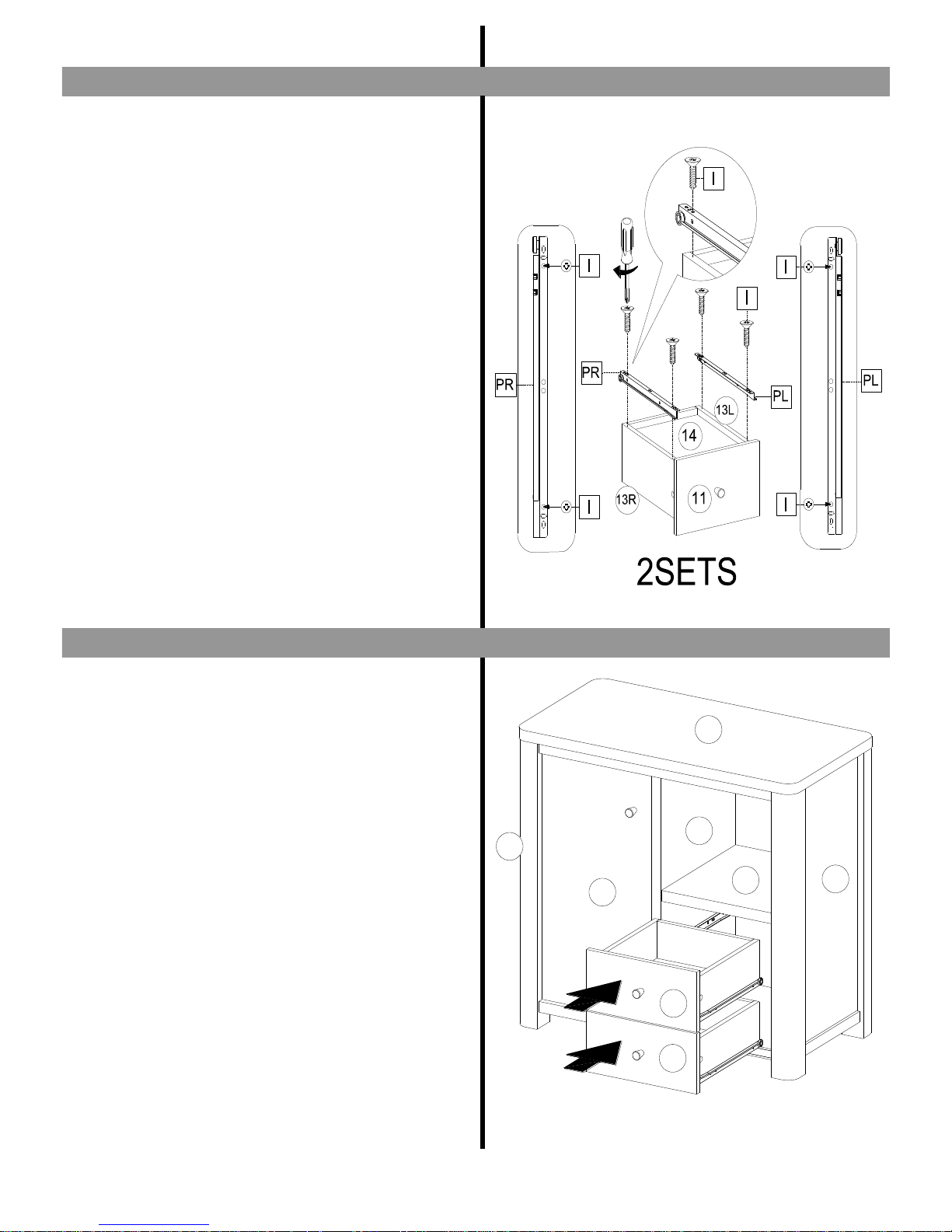
- Attach 1x male runner (PR) to the assembled unit by
tightening 2x screws ( I ) clockwise with a cross-blade
screwdriver.
- Attach 1x male runner (PL) to the assembled unit by
tightening 2x screws ( I ) clockwise with a cross-blade
screwdriver.
- Repeat this step for the remaining assembled drawer.
- Insert the drawers to the assembled unit.
STEP TWENTY ONE
STEP TWENTY
1
2
3R
3L
5
7
9
2
5
2
5
9
2
7
5
7
3L
2
7
3L
2
5
3
3L
3L
1
5
3R
1
4
4
4
4
2
3L
4
1
3R
3R
4
4
6
3R
7
2
3L
5
1
3L
2
8
3L
5
7
3R
1
10
3L
3L
10
10
2
3R
3L
8
7
5
1
13L
13L
13R
13R
12
11
13R
12
13L
12
13L
11
11
3L
10
5
7
3R
1
10 of 12
Page 11
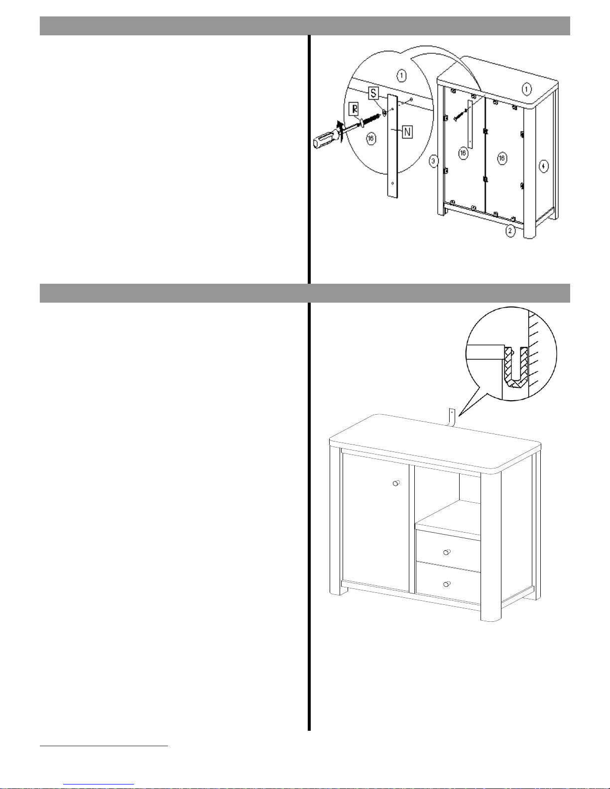
- Attach 1x wall bracket (N) to the edge of panel 1 and
using 1x washer(S) and secure by tightening 1x screw (R)
clockwise with a cross-blade screwdriver.
- Fix the other end of the bracket to the wall by using a
suitable screw ,washer and wall plug for your wall type.
Warning : Always ensure the area to be drilled is free
from hidden electrical wires, water and gas pipes.
NB : Wall fixing are not included. Please source suitable
fixing for your wall type. If in doubt please consult a
qualified trades person.
Next Retail Ltd, Desford Road, Leicester, LE19 4AT
STEP TWENTY THREE
STEP TWENTY TWO
1
2
3R
3L
5
7
9
2
5
2
5
9
2
7
5
7
3L
2
7
3L
2
5
3
3L
3L
1
5
3R
1
4
4
4
4
2
3L
4
1
3R
3R
4
4
6
3R
7
2
3L
5
1
3L
2
8
3L
5
7
3R
1
10
3L
3L
10
10
2
3R
3L
8
7
5
1
13L
13L
13R
13R
12
11
13R
12
13L
12
13L
11
11
3L
10
5
7
3R
1
11 of 12
Page 12
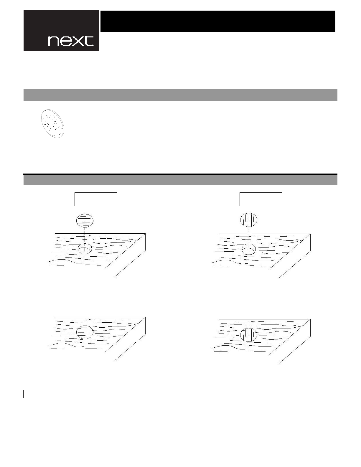
Note : Whilst position foil stickers to cover the holes. Ensure that you arrange them on the
centre of the holes before sticking. And ensure the grain direction of foil sticker have
to be in the same direction as current surface area.
The foil sticker is used for covering the camlock or predrilled holes of products.
They will help making the grain and colour is even and consistency.
FITTINGS
HOW TO USE THE FOIL STICKER.
Next Retail Ltd, Desford Road, Leicester, LE19 4AT
808953 BARLOW SMALL SIDEBOARD (FOIL STICKER)
Dia. 20 mm.
T x 22
Wrong
Correct
1
2
3R
3L
5
7
9
2
5
2
5
9
2
7
5
7
3L
2
7
3L
2
5
3
3L
3L
1
5
3R
1
4
4
4
4
2
3L
4
1
3R
3R
4
4
6
3R
7
2
3L
5
1
3L
2
8
3L
5
7
3R
1
10
3L
3L
10
10
2
3R
3L
8
7
5
1
13L
13L
13R
13R
12
11
13R
12
13L
12
13L
11
11
3L
10
5
7
3R
1
12 of 12
 Loading...