

Page 1
Fax (603) 753-6201
Toll-free 800-451-8255
(603) 753-6362
Penacook, NH 03303
88 Village Street
Instrument Company, Inc.
Beede Electrical
Contact Beede
W W W .BEEDE . C O M
548941 A • 09.13.11© 2011, Beede Electrical Instrument Co., Inc.
2” CAN Display
Operation
Manual
Product Family
CAN Instruments
NexSysLink
®
Page 2

i
About � � � � � � � � � � � � � � � � � � � � � � � � � � � � � � � � � � � � � � � � � � � � � � � � � � � � � � � � � � � � � � � � � � � � � � � � � �iii
Scope � � � � � � � � � � � � � � � � � � � � � � � � � � � � � � � � � � � � � � � � � � � � � � � � � � � � � � � � � � � � � � � � � � � � � � � � � �iii
Precongured Instruments � � � � � � � � � � � � � � � � � � � � � � � � � � � � � � � � � � � � � � � � � � � � � � � � � � � � � iv
Stand-Alone and Master Node Congurations � � � � � � � � � � � � � � � � � � � � � � � � � � � � � � � � � � �iv
Product Outline Drawing � � � � � � � � � � � � � � � � � � � � � � � � � � � � � � � � � � � � � � � � � � � � � � � � � � � � � � � v
Menu Navigation � � � � � � � � � � � � � � � � � � � � � � � � � � � � � � � � � � � � � � � � � � � � � � � � � � � � � � � � � � � � � � � 1
Menu/Enter/Reset Switch � � � � � � � � � � � � � � � � � � � � � � � � � � � � � � � � � � � � � � � � � � � � � � � � � � � � � � � � � � � � � � �1
Up Switch � � � � � � � � � � � � � � � � � � � � � � � � � � � � � � � � � � � � � � � � � � � � � � � � � � � � � � � � � � � � � � � � � � � � � � � � � � � � � � 1
Down Switch � � � � � � � � � � � � � � � � � � � � � � � � � � � � � � � � � � � � � � � � � � � � � � � � � � � � � � � � � � � � � � � � � � � � � � � � � � � 1
Switch Icon Conventions � � � � � � � � � � � � � � � � � � � � � � � � � � � � � � � � � � � � � � � � � � � � � � � � � � � � � � � � � � � � � � � � 1
Selection Arrow Cursor � � � � � � � � � � � � � � � � � � � � � � � � � � � � � � � � � � � � � � � � � � � � � � � � � � � � � � � � � � � � � � � � � 2
Menu Scrolling Icons� � � � � � � � � � � � � � � � � � � � � � � � � � � � � � � � � � � � � � � � � � � � � � � � � � � � � � � � � � � � � � � � � � � � 2
Blinking Bar Cursor � � � � � � � � � � � � � � � � � � � � � � � � � � � � � � � � � � � � � � � � � � � � � � � � � � � � � � � � � � � � � � � � � � � � � 3
Start-up Routine � � � � � � � � � � � � � � � � � � � � � � � � � � � � � � � � � � � � � � � � � � � � � � � � � � � � � � � � � � � � � � � � 4
Default CAN Parameter Screen � � � � � � � � � � � � � � � � � � � � � � � � � � � � � � � � � � � � � � � � � � � � � � � � � � 4
Viewing CAN Parameters � � � � � � � � � � � � � � � � � � � � � � � � � � � � � � � � � � � � � � � � � � � � � � � � � � � � � � � 4
Main Menu � � � � � � � � � � � � � � � � � � � � � � � � � � � � � � � � � � � � � � � � � � � � � � � � � � � � � � � � � � � � � � � � � � � � � 4
Maintenance Hours or Vehicle Trip � � � � � � � � � � � � � � � � � � � � � � � � � � � � � � � � � � � � � � � � � � � � � � � � � � � � � �5
Faults Active � � � � � � � � � � � � � � � � � � � � � � � � � � � � � � � � � � � � � � � � � � � � � � � � � � � � � � � � � � � � � � � � � � � � � � � � � � � �6
Viewing Active Faults � � � � � � � � � � � � � � � � � � � � � � � � � � � � � � � � � � � � � � � � � � � � � � � � � � � � � � � � � � � � � � � � � � � 7
Warnings Active � � � � � � � � � � � � � � � � � � � � � � � � � � � � � � � � � � � � � � � � � � � � � � � � � � � � � � � � � � � � � � � � � � � � � � � � 8
Viewing Active Warnings � � � � � � � � � � � � � � � � � � � � � � � � � � � � � � � � � � � � � � � � � � � � � � � � � � � � � � � � � � � � � � � � 9
Faults Stored � � � � � � � � � � � � � � � � � � � � � � � � � � � � � � � � � � � � � � � � � � � � � � � � � � � � � � � � � � � � � � � � � � � � � � � � � �10
Alarms � � � � � � � � � � � � � � � � � � � � � � � � � � � � � � � � � � � � � � � � � � � � � � � � � � � � � � � � � � � � � � � � � � � � � � � � � � � � � � � �11
Alarms Menu � � � � � � � � � � � � � � � � � � � � � � � � � � � � � � � � � � � � � � � � � � � � � � � � � � � � � � � � � � � � � � � � � � � � �12
Enabling/Disabling Alarms � � � � � � � � � � � � � � � � � � � � � � � � � � � � � � � � � � � � � � � � � � � � � � � � � � � � � � �13
Viewing Alarms � � � � � � � � � � � � � � � � � � � � � � � � � � � � � � � � � � � � � � � � � � � � � � � � � � � � � � � � � � � � � � � � � �14
Alarm Conguration � � � � � � � � � � � � � � � � � � � � � � � � � � � � � � � � � � � � � � � � � � � � � � � � � � � � � � � � � � � � � �15
Adding an Alarm or Alarms � � � � � � � � � � � � � � � � � � � � � � � � � � � � � � � � � � � � � � � � � � � � � � � � � � � � � � �16
Editing Alarms � � � � � � � � � � � � � � � � � � � � � � � � � � � � � � � � � � � � � � � � � � � � � � � � � � � � � � � � � � � � � � � � � � �18
Deleting Alarms � � � � � � � � � � � � � � � � � � � � � � � � � � � � � � � � � � � � � � � � � � � � � � � � � � � � � � � � � � � � � � � � �19
Mute � � � � � � � � � � � � � � � � � � � � � � � � � � � � � � � � � � � � � � � � � � � � � � � � � � � � � � � � � � � � � � � � � � � � � � � � � � � � � � � � � �20
Setup Menu � � � � � � � � � � � � � � � � � � � � � � � � � � � � � � � � � � � � � � � � � � � � � � � � � � � � � � � � � � � � � � � � � � � 21
Backlight � � � � � � � � � � � � � � � � � � � � � � � � � � � � � � � � � � � � � � � � � � � � � � � � � � � � � � � � � � � � � � � � � � � � � � � � � � � � � �22
Lamp On & Lamp O � � � � � � � � � � � � � � � � � � � � � � � � � � � � � � � � � � � � � � � � � � � � � � � � � � � � � � � � � � � � �22
Setting Units � � � � � � � � � � � � � � � � � � � � � � � � � � � � � � � � � � � � � � � � � � � � � � � � � � � � � � � � � � � � � � � � � � � � � � � � � �23
Popups Notication Screens � � � � � � � � � � � � � � � � � � � � � � � � � � � � � � � � � � � � � � � � � � � � � � � � � � � � � � � � � � �24
Setting Popups � � � � � � � � � � � � � � � � � � � � � � � � � � � � � � � � � � � � � � � � � � � � � � � � � � � � � � � � � � � � � � � � � � � � � � � �25
Display � � � � � � � � � � � � � � � � � � � � � � � � � � � � � � � � � � � � � � � � � � � � � � � � � � � � � � � � � � � � � � � � � � � � � � � � � � � � � � � �26
1 or 2 Parameter Display � � � � � � � � � � � � � � � � � � � � � � � � � � � � � � � � � � � � � � � � � � � � � � � � � � � � � � � � � �27
Set Contrast � � � � � � � � � � � � � � � � � � � � � � � � � � � � � � � � � � � � � � � � � � � � � � � � � � � � � � � � � � � � � � � � � � � � � �28
Video Mode Formats � � � � � � � � � � � � � � � � � � � � � � � � � � � � � � � � � � � � � � � � � � � � � � � � � � � � � � � � � � � � �29
Set Video � � � � � � � � � � � � � � � � � � � � � � � � � � � � � � � � � � � � � � � � � � � � � � � � � � � � � � � � � � � � � � � � � � � � � � � �30
Trip Mode � � � � � � � � � � � � � � � � � � � � � � � � � � � � � � � � � � � � � � � � � � � � � � � � � � � � � � � � � � � � � � � � � � � � � � � � � � � � �31
Alarm Output � � � � � � � � � � � � � � � � � � � � � � � � � � � � � � � � � � � � � � � � � � � � � � � � � � � � � � � � � � � � � � � � � � � � � � � � �32
Firmware Information � � � � � � � � � � � � � � � � � � � � � � � � � � � � � � � � � � � � � � � � � � � � � � � � � � � � � � � � � � � � � � � � � �33
Implementation of SAE J1939 Parameters � � � � � � � � � � � � � � � � � � � � � � � � � � � � � � � � � � � � � � 34
Parameter Icons & Descriptions � � � � � � � � � � � � � � � � � � � � � � � � � � � � � � � � � � � � � � � � � � � � � � � � 35
Menu Navigation Icon Descriptions � � � � � � � � � � � � � � � � � � � � � � � � � � � � � � � � � � � � � � � � � � � � 36
Table of Contents
NexSysLink® 2" Stand-Alone CAN Display Operation Manual SAE J1939
Page 3

ii
List of Figures
Figure 1-1: Menu Scrolling and Option Selection � � � � � � � � � � � � � � � � � � � � � � � � � � � � � � � � 2
Figure 1-2: Blinking Bar Cursor � � � � � � � � � � � � � � � � � � � � � � � � � � � � � � � � � � � � � � � � � � � � � � � � � 3
Figure 1-3: Accessing the Main Menu � � � � � � � � � � � � � � � � � � � � � � � � � � � � � � � � � � � � � � � � � � � 4
Figure 1-4: Accessing and Resetting Maintenance Hours and Vehicle Trip Logs � � � 5
Figure 1-5: Fault Notication and Information Screens � � � � � � � � � � � � � � � � � � � � � � � � � � � 6
Figure 1-6: Viewing Active Faults � � � � � � � � � � � � � � � � � � � � � � � � � � � � � � � � � � � � � � � � � � � � � � � 7
Figure 1-7: Warning Notication and Information Screens � � � � � � � � � � � � � � � � � � � � � � � 8
Figure 1-8: Viewing Active Warnings � � � � � � � � � � � � � � � � � � � � � � � � � � � � � � � � � � � � � � � � � � � � 9
Figure 1-9: Faults Stored Information Screens � � � � � � � � � � � � � � � � � � � � � � � � � � � � � � � � � � 10
Figure 1-10: Alarms Menu Functions � � � � � � � � � � � � � � � � � � � � � � � � � � � � � � � � � � � � � � � � � � � 12
Figure 1-11: Enabling/Disabling Alarms � � � � � � � � � � � � � � � � � � � � � � � � � � � � � � � � � � � � � � � � 13
Figure 1-12: Alarm Screen Details � � � � � � � � � � � � � � � � � � � � � � � � � � � � � � � � � � � � � � � � � � � � � � 14
Figure 1-13: Viewing Alarms � � � � � � � � � � � � � � � � � � � � � � � � � � � � � � � � � � � � � � � � � � � � � � � � � � � 14
Figure 1-14: Add & Edit Alarm CAN Parameter Screen Details � � � � � � � � � � � � � � � � � � � 15
Figure 1-15: Menu Prompt Sequence with No Congured Alarms � � � � � � � � � � � � � � � 16
Figure 1-16: Menu Prompt Sequence with Previously Congured Alarms � � � � � � � 17
Figure 1-17: Editing an Alarm � � � � � � � � � � � � � � � � � � � � � � � � � � � � � � � � � � � � � � � � � � � � � � � � � � 18
Figure 1-18: Deleting an Alarm � � � � � � � � � � � � � � � � � � � � � � � � � � � � � � � � � � � � � � � � � � � � � � � � 19
Figure 1-19: Muting Faults, Warnings & Alarms � � � � � � � � � � � � � � � � � � � � � � � � � � � � � � � � � 20
Figure 1-20: Setup Menu Functions � � � � � � � � � � � � � � � � � � � � � � � � � � � � � � � � � � � � � � � � � � � � 21
Figure 1-21: Setting Backlight Intensity � � � � � � � � � � � � � � � � � � � � � � � � � � � � � � � � � � � � � � � � 22
Figure 1-22: Setting Units � � � � � � � � � � � � � � � � � � � � � � � � � � � � � � � � � � � � � � � � � � � � � � � � � � � � � 23
Figure 1-23: Popup Fault, Warning & Alarm Screens � � � � � � � � � � � � � � � � � � � � � � � � � � � � 24
Figure 1-24: Setting Popup Status � � � � � � � � � � � � � � � � � � � � � � � � � � � � � � � � � � � � � � � � � � � � � 25
Figure 1-25: Display Menu � � � � � � � � � � � � � � � � � � � � � � � � � � � � � � � � � � � � � � � � � � � � � � � � � � � � � 26
Figure 1-26: 1 and 2 CAN Parameter Display Formats � � � � � � � � � � � � � � � � � � � � � � � � � � � 27
Figure 1-27: Setting 1 or 2 Parameter Display Lines � � � � � � � � � � � � � � � � � � � � � � � � � � � � � 27
Figure 1-28: Setting LCD Contrast � � � � � � � � � � � � � � � � � � � � � � � � � � � � � � � � � � � � � � � � � � � � � � 28
Figure 1-29: Video Mode Formats � � � � � � � � � � � � � � � � � � � � � � � � � � � � � � � � � � � � � � � � � � � � � � 29
Figure 1-30: Setting LCD Background Color Scheme (Video Mode) � � � � � � � � � � � � � � 30
Figure 1-31: Setting Hours or Miles for Main Menu Display � � � � � � � � � � � � � � � � � � � � � 31
Figure 1-32: Setting Alarm Output Pin Status � � � � � � � � � � � � � � � � � � � � � � � � � � � � � � � � � � � 32
Figure 1-33: Viewing Firmware Revision � � � � � � � � � � � � � � � � � � � � � � � � � � � � � � � � � � � � � � � � 33
NexSysLink® 2" Stand-Alone CAN Display Operation Manual SAE J1939
Page 4

iii
• About
The 2" Stand-Alone CAN Display instrument is a member of the Beede
NexSysLink® CAN instruments product family�
This instrument directly reads SAE J1939 compliant CAN messages and
displays the message information on a sunlight visible, transective dotmatrix LCD� Like all NexSysLink® instruments, this product eliminates the
need for a translation “black box” between an ECM/ECU and the instrument
itself making wiring and installation simple and fast�
Three discrete alert LEDs provide users with visual notication of engine/
vehicle/vessel parameter faults, warnings and malfunctions�
Built-in, sealed, tactile switches allow users to easily navigate the intuitive
menu driven user interface� The integration of the switches also reduces
wiring to further reduce installation time and costs; essentially providing a
plug-and-play product�
Although designed to "stand-alone", the instrument may be used
in conjunction with other NexSysLink® instruments to monitor your
equipment�
• Scope
This manual describes how to navigate the LCD interface and use the many
features the instrument provides� Although the interface is intuitive and
easy to navigate, this operation manual provides users with a resource to
realize the full potential and capabilities of the instrument�
Covered in this manual are display options, menu navigation and menu
function usage�
Although some wiring connections are noted for easy reference, this
manual does not cover complete installation mounting and wiring
requirements� Please refer to the installation instruction sheet for proper
installation�
NexSysLink® 2" Stand-Alone CAN Display Operation Manual SAE J1939
Page 5

iv
• Precongured Instruments
Some instruments are precongured at the factory to individual OEM
specications to best meet the needs of the application and end user�
Precongured features include but may not be limited to alarm
conguration, single or dual line display and backlight intensity�
Precongured features are easily modied to satisfy personal preferences�
• Stand-Alone and Master Node Congurations
The instrument is primarily designed to "stand-alone" in applications
where ease of use, limited space and simple installation are critical
criteria in choosing the type of engine/vehicle/vessel monitoring
electronics�
In order to satisfy a wide range of application demands, the hardware
of the 2" CAN Display can be factory congured to drive a maximum
of 16 Beede NexSysLink® Slave Node Instruments (SNI) or Analog
Slave Node Instruments (ASNI)�
The ability to connect with ASNI gauges expands the instruments
capabilities to display analog inputs such as fuel level or air pressure�
When factory congured to drive Beede NexSysLink® SNI or
ASNI gauges, Pin 4 of the 6 pin connector is used for serial data
communication among the instruments�
NexSysLink® 2" Stand-Alone CAN Display Operation Manual SAE J1939
Page 6
v
NexSysLink® 2" Stand-Alone CAN Display Operation Manual SAE J1939
© 2011 Beede Electrical Instrument Co., Inc.
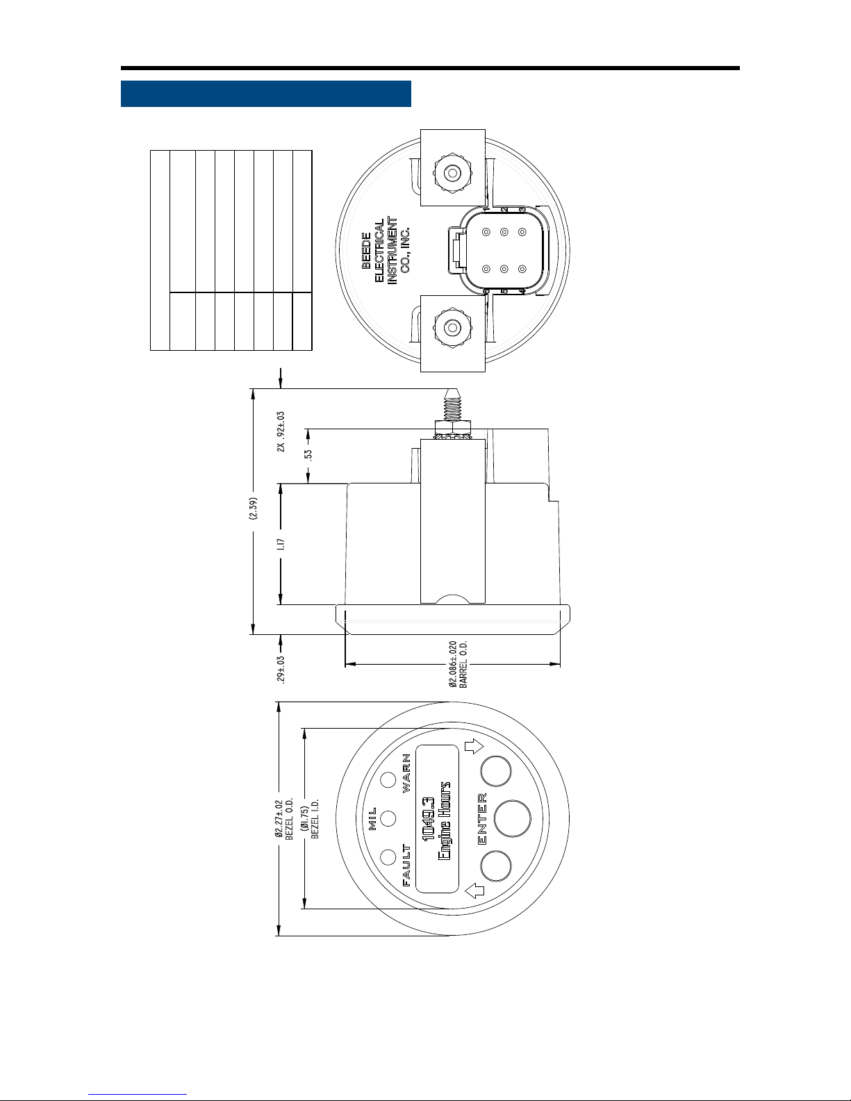
• Product Outline Drawing
Mounting hole size:
Ø2.125±.015”
(Ø53.98±0.38mm)
Mounting hardware torque:
6 lb-in
(0.68 N-m) max.
Refer to the appropriate
Beede installation instruction
sheet for complete installation
requirements.
Dimensions shown are in inches.
6 Pin Connector Wiring Table
Connection
Name
Battery +
Pin
Number
1
Ground2
Switched Output3
Lamp (B+) or Serial Data4
CAN-H5
CAN-L6
Page 7
1
NexSysLink® 2" Stand-Alone CAN Display Operation Manual SAE J1939
© 2011 Beede Electrical Instrument Co., Inc.
• Menu Navigation
Menu navigation is accomplished through three built-in momentary switches� The switch functions are
MENU/ENTER/RESET, UP and DOWN�
• Menu/Enter/Reset Switch
As its name suggests, this switch serves several purposes when navigating the user interface� The
function depends upon the context of the menu option but is labeled ENTER on the instrument�
Menu Function: Pressing and holding this switch for approximately three seconds when any parameter
screen is displayed brings up the main menu�
Enter Function: Pressing and releasing this switch provides enter functionality when the operator is
required to choose a menu item, parameter, or value�
Reset Function: Pressing and holding this switch resets the selected trip miles or maintenance hour
value to zero�
• Up Switch
Pressing and releasing the Up switch scrolls up through the CAN parameter list, menu choices or
increases a value one item/unit at a time�
Pressing and holding the Up switch continuously scrolls up through the CAN parameter list, menu
choices or increases a value until the end of the menu choices or maximum value is reached�
• Down Switch
The Down switch functions identical to the Up switch with the exception that its direction for all lists,
menu choices and values is down or decreasing�
• Switch Icon Conventions
Throughout this manual, icons are used to indicate actions required by the user to navigate the menus�
Below are descriptions and the corresponding action to be taken when they appear�
Press and release Menu/Enter/Reset switch icon�
The presence of this icon in the manual indicates when to press and release
the Menu/Enter/Reset switch�
Press and hold Menu/Enter/Reset switch icon�
The presence of this icon in the manual indicates when to press and hold
the Menu/Enter/Reset switch for approximately three seconds�
Press Up switch icon�
The presence of this icon in the manual indicates when to press and release the Up switch�
Users may also choose to press and hold the Up switch if necessary�
Press Down switch icon�
The presence of this icon in the manual indicates when to press and release the Down
switch� Users may also choose to press and hold the Down switch if necessary�
Page 8
2
NexSysLink® 2" Stand-Alone CAN Display Operation Manual SAE J1939
© 2011 Beede Electrical Instrument Co., Inc.
• Menu Navigation (Continued)
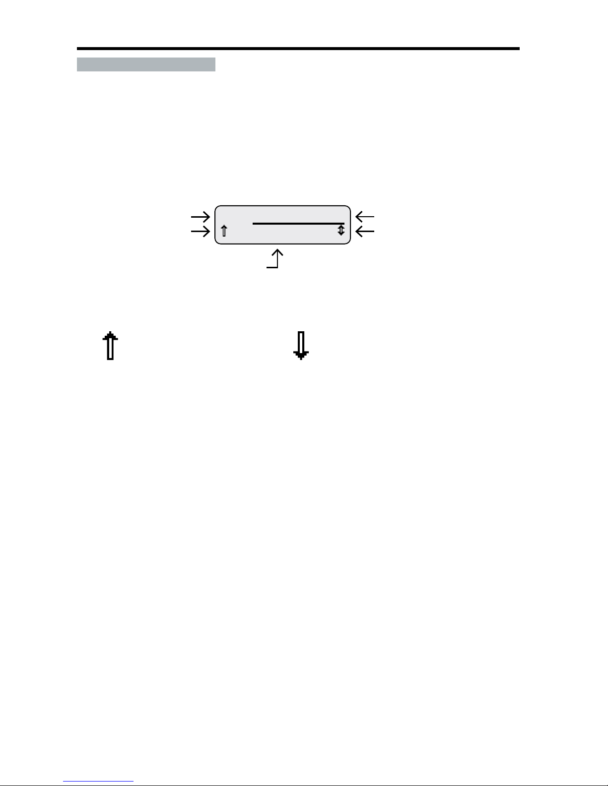
The user interface contains various icons and indicators to guide users for item selection and/or input
while navigating the menus� The selection arrow, menu scrolling icon and blinking bar cursors appear
frequently throughout the menus�
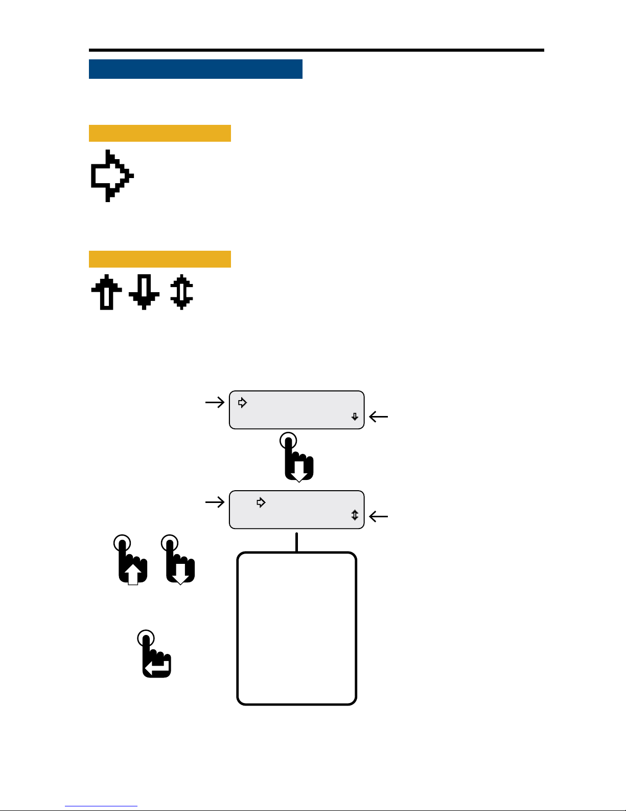
• Selection Arrow Cursor
The selection arrow cursor, shown at left, identies adjacent menu items as the current
selection� Pressing the Enter switch selects the menu item/function or value adjacent to
the arrow cursor�
Pressing and releasing an Up or Down switch moves the selection arrow up or down a
menu list one item at a time until the beginning or end of the list is reached� Pressing and
holding the Up or Down switch continuously moves the selection arrow up and down a menu list until
the switch is released or the beginning or end of the list is reached�
• Menu Scrolling Icons
A menu scrolling icon appears in the lower right corner of the display to
indicate if more menu options appear only above, only below or above and
below the menu option or options currently displayed�
Figure 1-1: Menu Scrolling and Option Selection
Menu scrolling icon indicating
more options appear above
and below those shown.
Selection Arrow Cursor
Warnings Acve
Faults Active
Menu scrolling icon indicating
more options appear below
those shown.
Selection Arrow Cursor
Faults Active
Maintenance Hours
First Main Menu Screen
Note: Many menu screen diagrams
in this manual only show the rst
two options of the entire menu.
If more than two options are
available within a menu, a listing
of all the options will appear
below the menu diagram.
Complete Main Menu
Function List
Maintenance Hours
Faults Active
Warnings Active
Faults Stored
Alarms
Mute Audio Alarm
Setup
Information
Exit
To select option
adjacent to
selection arrow cursor
To scroll up and down
a menu option list
Page 9
3
NexSysLink® 2" Stand-Alone CAN Display Operation Manual SAE J1939
© 2011 Beede Electrical Instrument Co., Inc.
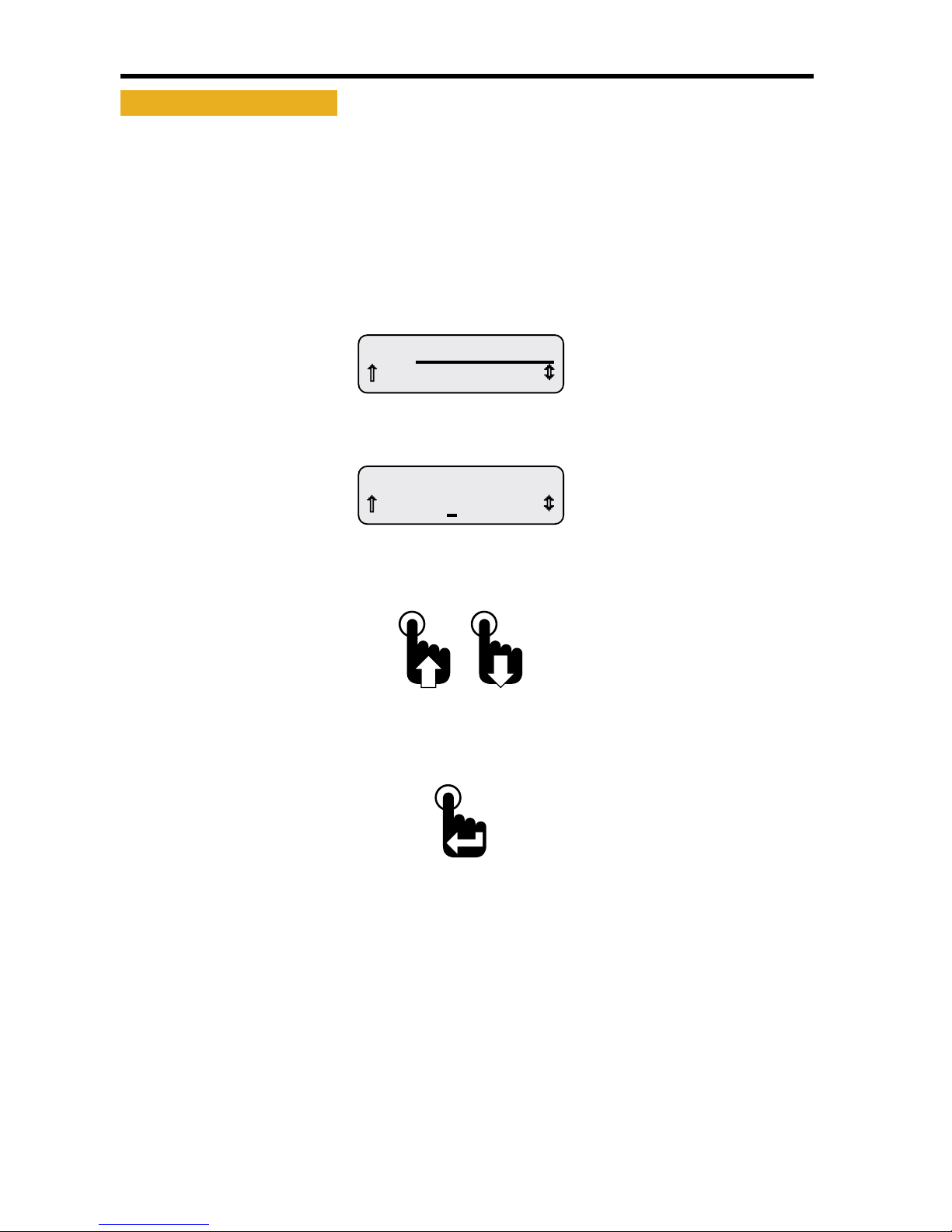
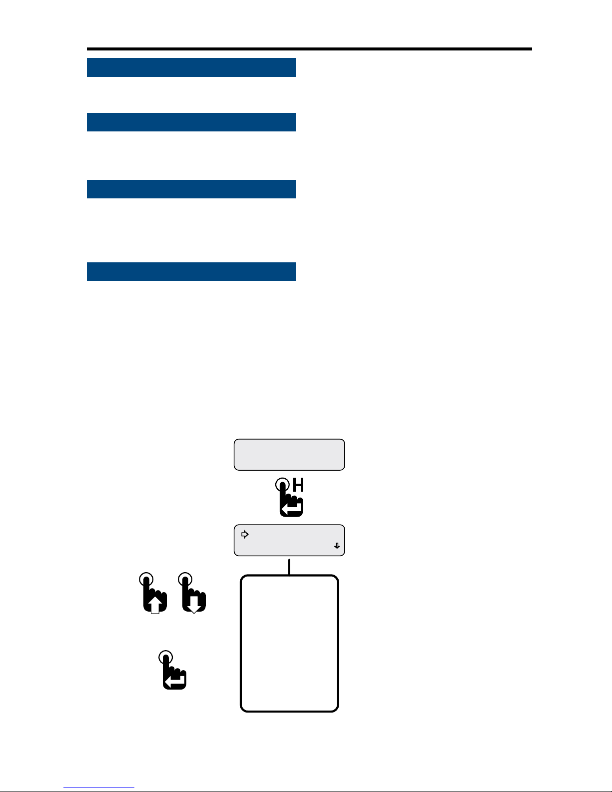
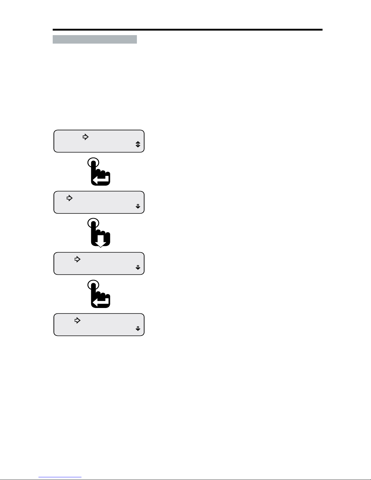
• Blinking Bar Cursor
A blinking bar cursor appearing beneath a numeric value or CAN parameter indicates the item may be
changed by pressing or pressing and holding either the Up or Down switches�
When a numeric value appears above a blinking bar cursor, pressing or pressing and holding the Up or
Down switch increases or decreases the value until the maximum value limits are reached�
When a CAN parameter appears above a blinking bar cursor, pressing or pressing and holding either the
Up or Down switch scrolls through the list of CAN parameters until the end of the list is reached�
Figure 1-2: Blinking Bar Cursor
0 A
A1 Baery Current
Blinking Bar Cursor
located under amperage value
0.0 bar
A1 Coolant Pressure
Blinking Bar Cursor
located under parameter name
Pressing the Up or Down switch
changes the CAN parameter or value until the
end of the list or limits of the value range is reached.
Pressing the Enter switch when
the desired parameter or value is
displayed accepts the parameter or value.
Page 10
4
NexSysLink® 2" Stand-Alone CAN Display Operation Manual SAE J1939
© 2011 Beede Electrical Instrument Co., Inc.
• Start-up Routine
Upon Instrument start-up, the three alert LEDs will ash then the Beede logo followed by the SAE logo
appear for approximately three seconds�
• Default CAN Parameter Screen
After completion of the start-up routine, the Engine Hours CAN parameter appears� If power was
removed from the instrument with a dierent parameter displayed, Engine Hours will appear when
power is reapplied to the instrument�
• Viewing CAN Parameters
All actively broadcast SAE J1939 CAN parameters implemented by the instrument are available for
viewing� See "Implementation of SAE J1939 Parameters" on page 34� Press the Up or Down switch to
nd and view the desired parameter� The displayed parameter will not time out and remains displayed
until a dierent parameter is selected for viewing or power is removed from the instrument�
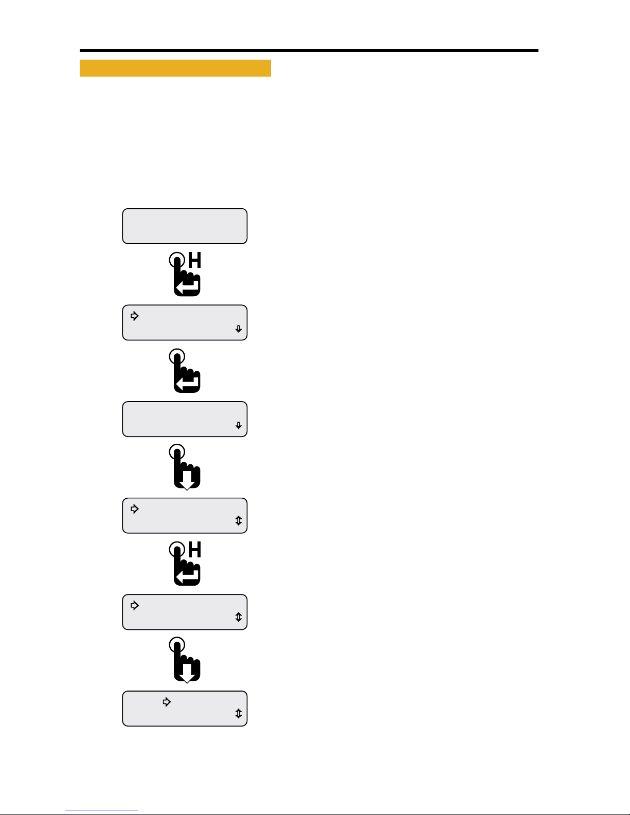
• Main Menu
The Main Menu contains functions to congure the LCD (Liquid Crystal Display), set alarms or view ECM
faults and warnings� Access the Main Menu by pressing and holding the Menu/Enter/Reset switch for
approximately three seconds while any CAN parameter screen is displayed�
Like all menus with multiple functions/options, only the rst two Main Menu functions/options appear
on the screen� Access the other functions/options by scrolling down the menu list using the Down
switch� Use the Up switch to scroll back up the Main Menu function/option list�
The Main Menu and all the functions within it except Maintenance Hours and Vehicle Trip functions will
display for approximately 30 seconds if no user activity is detected� The previously displayed parameter
reappears after 30 seconds of inactivity�
Figure 1-3: Accessing the Main Menu
Faults Active
Maintenance Hours
Engine Hours
1049.3
* Either Maintenance Hours or
Vehicle Trip appears as the rst
Main Menu function depending
upon the Main Menu-Setup-Trip Mode
conguration.
Main Menu-Setup-Trip-Hours
displays Maintenance Hours.
Main Menu-Setup-Trip-Distance
displays Vehicle Trip.
Complete Main Menu
Function List
*Maintenance Hours
Faults Active
Warnings Active
Faults Stored
Alarms
Mute Audio Alarm
Mute-Temporary
Setup
Information
Exit
To select a Main Menu
function adjacent to the
selection arrow cursor
To scroll up and down
the Main Menu list
First Main Menu Screen
Parameter Display Screen.
Engine Hours shown as an
example only.
Page 11
5
NexSysLink® 2" Stand-Alone CAN Display Operation Manual SAE J1939
© 2011 Beede Electrical Instrument Co., Inc.
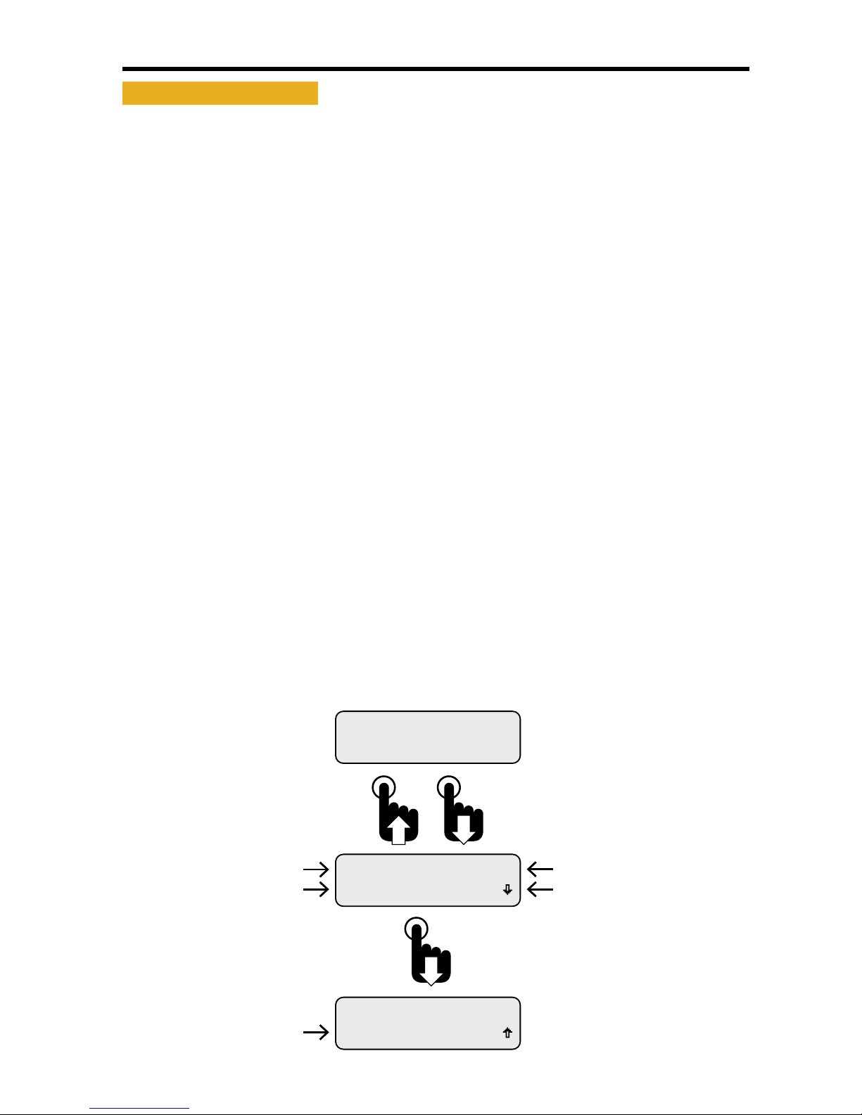
• Maintenance Hours or Vehicle Trip
Depending upon the conguration of the instrument, either Maintenance Hours or Vehicle Trip appears
as the rst Main Menu function� See "Trip Mode" on page 31 for setting hours or trip as the rst Main
Menu function�
The instrument provides two resettable maintenance hour and vehicle trip logs� The Maintenance
Hours or Vehicle Trip function allows users to view and reset any of the hour or trip logs�
Figure 1-4: Accessing and Resetting Maintenance Hours and Vehicle Trip Logs
Exit
Return
308.0Hour2
0.0Hour1
308.0Hour2
1049.3Hour1
308.0Hour2
1049.3Hour1
Faults Active
Maintenance Hours
Engine Hours
1049.3
Scroll down to place the selection arrow cursor next
to the Return option then press the Enter switch
to access the Main Menu.
Scroll down to place the selection arrow cursor next
to the Exit option then press the Enter switch to
return to the last displayed CAN parameter screen.
Hour1 log reset to zero.
Hour2 log may be reset by moving the selection
arrow cursor down to Hour2 log then pressing and
holding the Enter switch.
Selection arrow cursor appears next to Hour1 log.
Press and hold Enter switch to reset Hour1 log or press
the Down switch to place selection arrow cursor next
to Hour2 log.
Maintenance hour log screen appears.
Press Down switch to select an hour log.
Note: Maintenance Hour and trip log displays do not
time out after 30 seconds and return the last
CAN parameter displayed like most menu displays.
First Main Menu screen appears with the selection
arrow cursor next to Maintenance Hours.
Press the Enter switch to display maintenance hour logs.
Note: Instrument may be congured for vehicle trip
instead of maintenance hours.
With a CAN parameter displayed, press and
hold the Enter switch to open the Main Menu.
Engine Hours CAN parameter shown as an example only.
Page 12
6
NexSysLink® 2" Stand-Alone CAN Display Operation Manual SAE J1939
© 2011 Beede Electrical Instrument Co., Inc.
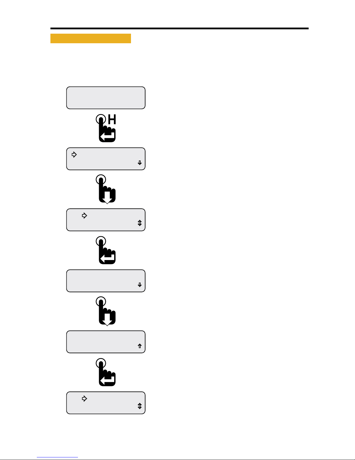
• Faults Active
Faults are an indicator of a severe vehicle problem as reported by the ECM/ECU that warrants stopping
the engine/vehicle/vessel� Users should consult the owners manual or a service technician to correct
the fault condition or conditions�
When a fault condition occurs, the instruments internal audible alarm and Fault LED are activated�
The internal audible alarm is temporarily muted by pressing the Enter switch�
An external audible device connected to output pin 3 of the six pin connector will also be muted if the
setup option Alarm Output, Main Menu-Setup-Alarm Output, is set to Audio� See "Alarm Output" on
page 32 to congure alarm output pin�
The Main Menu-Faults Active option allows users to view the parameter or parameters causing fault
notication� If popups for fault conditions is enabled, a fault notication screen appears� Refer to
"Setting Popups" on page 25�
The Faults Active function within the Main Menu allows users to view details for all currently active
faults�
Fault information includes the following:
DM1 (Diagnostic Message) for active faults or DM2 for stored faults
Fault number and total fault quantity, e�g�, 1 of 3
SPN (Suspect Parameter Number) numerically identies the parameter per the CAN protocol
FMI (Fault Mode Indicator) number to further identify the faults characteristic
Fault Name� Appears if the CAN parameter is implemented in the instruments rmware�
See"Implementation of SAE J1939 Parameters" on page 34
The active fault display will not time out after 30 seconds� Press the Enter switch to exit viewing faults
and return to the Faults Active option of the Main Menu�
Figure 1-5: Fault Notication and Information Screens
Eng Oil Pressure
DM1 Fault 1 of 1
SPN 100 FMI 3
DM1 Fault 1 of 1
FAULT
Pressing the Down switch displays
the fault name instead of the
SPN number.
Fault Notication Screen Appears
if Popups are Enabled.
Refer to Setting Popups.
Pressing the Enter switch
clears the fault notication
and returns the last displayed
CAN parameter.
Failure Mode Indicator
Fault number of total faults
Suspect Parameter Number
Diagnostic Mode Number
Parameter Name
Page 13
7
NexSysLink® 2" Stand-Alone CAN Display Operation Manual SAE J1939
© 2011 Beede Electrical Instrument Co., Inc.
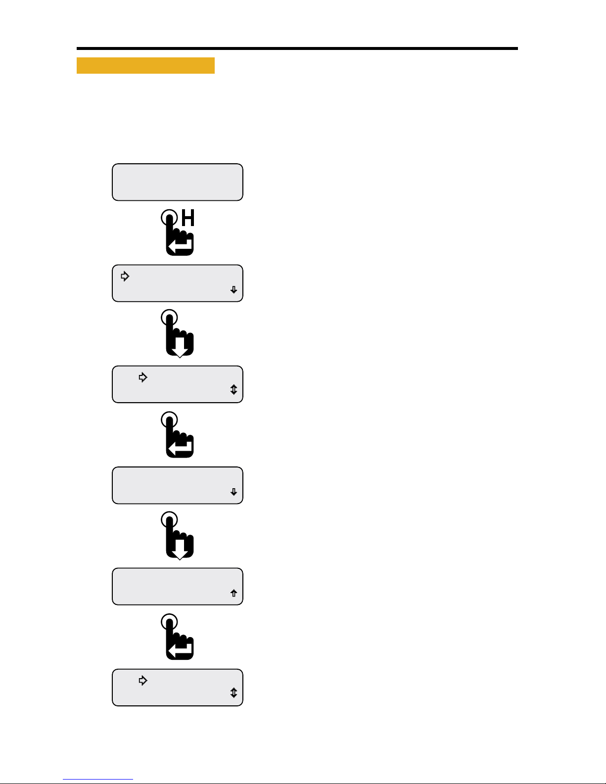
• Viewing Active Faults
If a fault information screen is cleared after it initially appears and the fault is still active, users can view
all the active fault information screens by using the Faults Active function of the Main Menu, Main Menu-
Active Faults�
Figure 1-6: Viewing Active Faults
Warnings Active
Faults Active
Eng Oil Pressure
DM1 Fault 1 of 1
SPN 100 FMI 0
DM1 Fault 1 of 1
Warnings Active
Faults Active
Faults Active
Maintenance Hours
Engine Hours
1049.3
Pressing the Enter switch with any of the active fault
detail screens visible returns the selection arrow
cursor next to the Faults Active option within the
Main Menu.
Scrolling down shows the fault name instead of the
SPN number. If more than one fault is active, scroll
down to see the subsequent fault details.
The fault screen appears listing the number of faults
(1 of 1 in this example), SPN and FMI numbers.
Scroll down to view the fault parameter name.
With the selection arrow cursor next to the
Faults Active option, press the Enter switch to
begin viewing fault detailed information.
First Main Menu screen appears with selection
arrow cursor next to Maintenance Hours.
Press the Down switch to place the selection arrow
cursor next to the Faults Active option.
With a CAN parameter displayed, press and
hold the Enter switch to bring up the Main Menu.
Engine Hours parameter shown as an example only.
Page 14
8
NexSysLink® 2" Stand-Alone CAN Display Operation Manual SAE J1939
© 2011 Beede Electrical Instrument Co., Inc.
• Warnings Active
Warnings are an indicator of a vehicle problem as reported by the ECM/ECU that does not warrant
immediately stopping the vehicle or vessel� Users should consult the owners manual or a service
technician to correct the warning condition or conditions�
When a warning condition occurs, the instruments internal audible alarm and Warn LED are activated�
The internal audible alarm may be temporarily muted by pressing the Enter switch�
An external audible device connected to output pin 3 of the six pin connector will also be muted if the
setup option Alarm Output, Main Menu-Setup-Alarm Output, is set to Audio� See "Alarm Output" on
page 32 to congure alarm output pin�
The Main Menu-Warnings Active option allows users to view the parameter or parameters causing the
warning� If popups for warning conditions is enabled, a warning notication screen appears� Refer to
"Setting Popups" on page 25�
The built-in audible device will sound when a warning condition occurs if the Mute setting, Main Menu-
Mute Audio Alarm, is not set to Permanent� See "Mute" on page 20 for enabling the internal audible
device�
The active warning display will not time out after 30 seconds� Press the Enter switch to exit viewing
warnings and return to the Warnings Active option of the Main Menu�
Figure 1-7: Warning Notication and Information Screens
Engine Hours
1049.3
WARNING
Eng Oil Pressure
Warning SPN 100
Pressing the Enter switch returns
the last displayed CAN parameter.
Engine Hours CAN parameter
shown as an example only.
A warning notication screen appears when
popups are enabled and a warning condition
occurs.
Refer to setting popups.
Menu Scroll Icon.
Appears only if more warnings
are present.
Suspect Parameter Number
Parameter Name
Warning Label
Page 15
9
NexSysLink® 2" Stand-Alone CAN Display Operation Manual SAE J1939
© 2011 Beede Electrical Instrument Co., Inc.
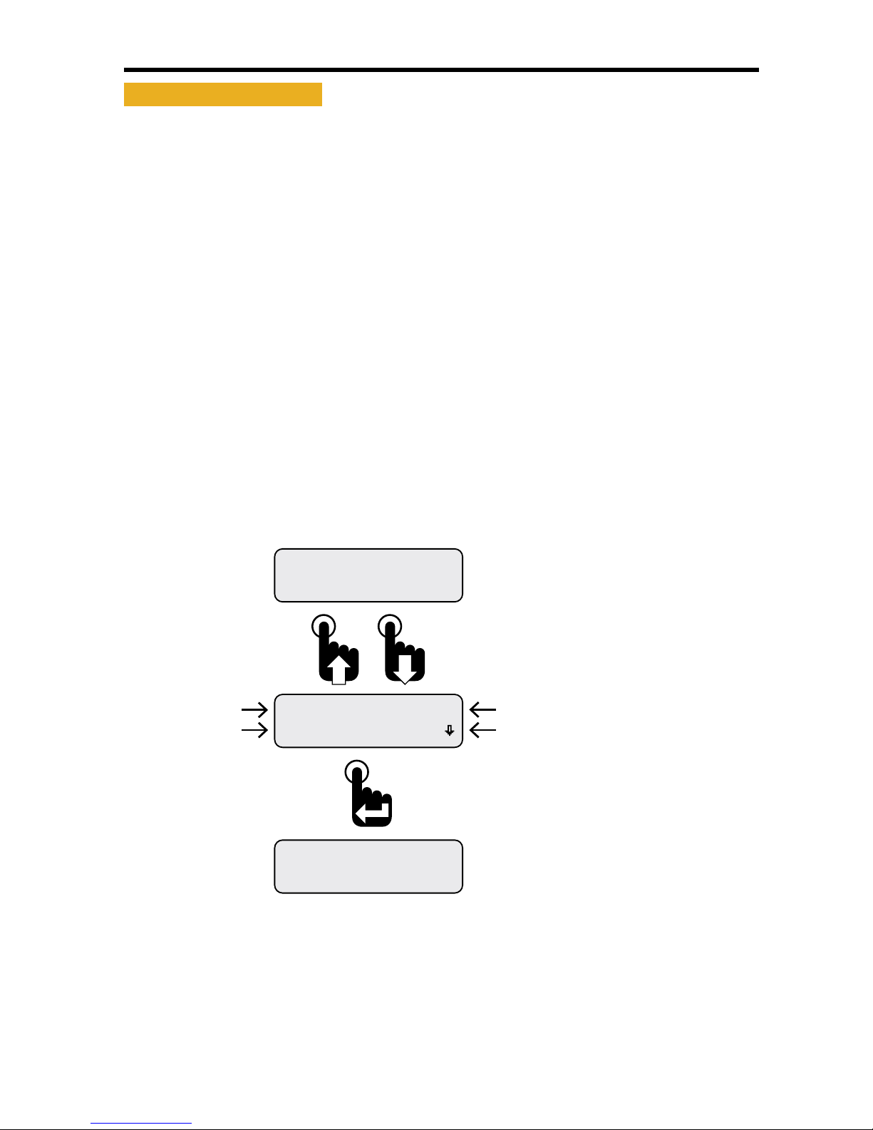
• Viewing Active Warnings
If a warning information screen is cleared after it initially appears and the warning is still active, users
can view all the active warning information screens by using the Warnings Active function of the Main
Menu, Main Menu-Warnings Active�
Figure 1-8: Viewing Active Warnings
Faults Stored
Warnings Active
Eng Oil Pressure
Warning SPN 100
Faults Stored
Warnings Active
Faults Active
Maintenance Hours
Engine Hours
1049.3
Pressing the Enter switch with any of the active
warnings detail screens visible returns the selection
arrow cursor next to the Warnings Active option
within the Main Menu.
The warning detail screen appears if at least one
warning is present. If multiple warnings are present,
the menu scroll down icon appears.
Scroll down to view other warnings or press the Enter
switch to return to the Warnings Active option of the
Main Menu.
Press the Enter switch with the selection arrow cursor
next to the Warnings Active option to view all current
system warnings.
First Main Menu screen appears with selection
arrow cursor next to Maintenance Hours.
Scroll down to place the selection arrow cursor
next to the Warnings Active option.
With a CAN parameter displayed, press and
hold the Enter switch to bring up the Main Menu.
Engine Hours parameter shown as an example only.
Page 16
10
NexSysLink® 2" Stand-Alone CAN Display Operation Manual SAE J1939
© 2011 Beede Electrical Instrument Co., Inc.
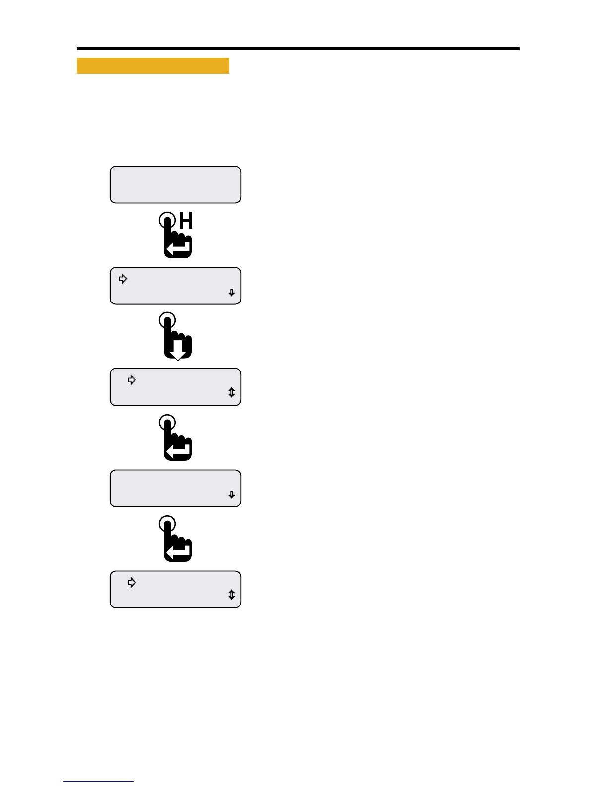
• Faults Stored
The instrument will display all DM2 (Diagnostic Mode) faults stored by the ECU� DM2 faults are
previously active diagnostic trouble codes�
Figure 1-9: Faults Stored Information Screens
Alarms
Faults Stored
Eng Oil Pressure
DM2 Fault 1 of 1
SPN 100 FMI 3
DM2 Fault 1 of 1
Alarms
Faults Stored
Faults Active
Maintenance Hours
Engine Hours
1049.3
Pressing the Enter switch with any of the stored faults
detail screens visible returns the selection arrow
cursor next to the Faults Stored option within the
Main Menu.
Scrolling down shows the fault name instead of the
SPN number if the parameter is implemented in the
instruments rmware.
If more than one stored fault is active, scroll down
to see the subsequent stored fault details.
The fault screen appears listing the number of stored
faults (1 of 1 in this example), SPN and FMI numbers.
Scroll down to view the fault parameter name.
With the selection arrow cursor next to
the Faults Stored option, press the Enter
switch to view stored faults.
First Main Menu screen appears with selection
arrow cursor next to Maintenance Hours.
Press the Down switch to place the selection arrow
cursor next to the Faults Stored option.
With a CAN parameter displayed, press and
hold the Enter switch to bring up the Main Menu.
Engine Hours parameter shown as an example only.
Page 17
11
NexSysLink® 2" Stand-Alone CAN Display Operation Manual SAE J1939
© 2011 Beede Electrical Instrument Co., Inc.
• Alarms
Alarms are user congured limits for CAN parameters used to alert operators when the parameter or
parameters exceeds those limits� Alarms help users protect a vehicle, vessel or equipment from damage
by providing an option to set operating notication limits for CAN parameters critical to the application�
A maximum of 15 parameters may be congured for alarm notication�
Note: Alarms are only a notication feature and do not disable or diminish the operation of a vehicle or
equipment�
Alarm settings are written to non-volatile memory and retained when power is removed from the
instrument�
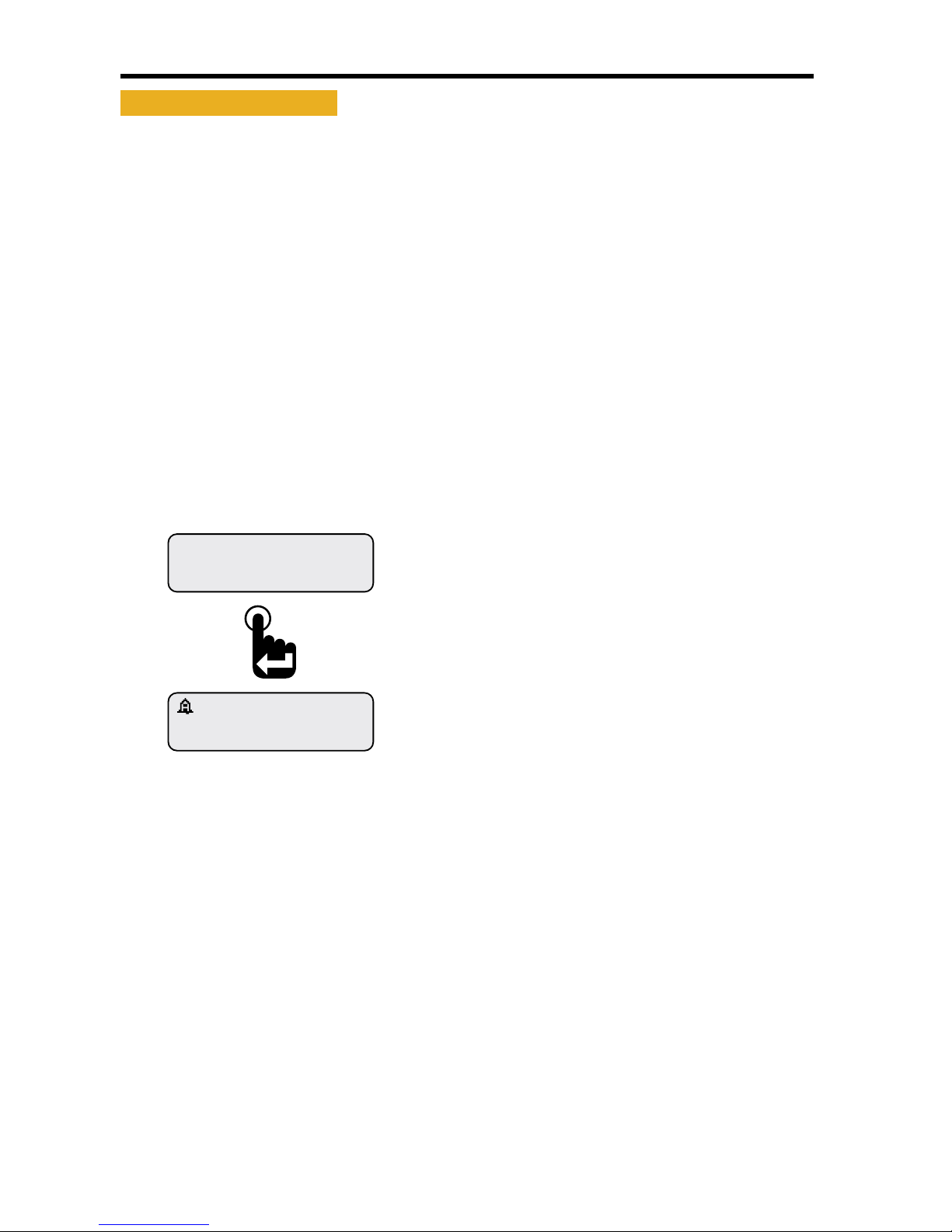
If alarms are congured and enabled, a blinking "Bell" icons appears in the upper left corner of the
current CAN parameter display screen once a parameter exceeds the set alarm limits� If popups for
alarm conditions is enabled, an alarm notication screen appears� Refer to "Setting Popups" on page
25�
The built-in audible device will sound when an alarm occurs if the Mute setting, Main Menu-Mute Audio
Alarm, is not set to Permanent� See "Mute" on page 20 for enabling the internal audible device�
Parameter Display Screen with Alarm “Bell” Icon
Engine Hours
1049.3
ALARM
Pressing the Enter switch clears the alarm notication
screen and returns the last displayed CAN parameter.
A blinking bell icon appears in the upper left corner of
the screen to indicate the alarm condition is still active.
An alarm notication screen appears when popups
are enabled and an alarm condition occurs.
Refer to setting popups.
Page 18
12
NexSysLink® 2" Stand-Alone CAN Display Operation Manual SAE J1939
© 2011 Beede Electrical Instrument Co., Inc.
• Alarms Menu
The Main Menu-Alarms function allows users to enable alarm notication, view the parameter or
parameters causing the alarm, edit existing alarms and add new alarms�
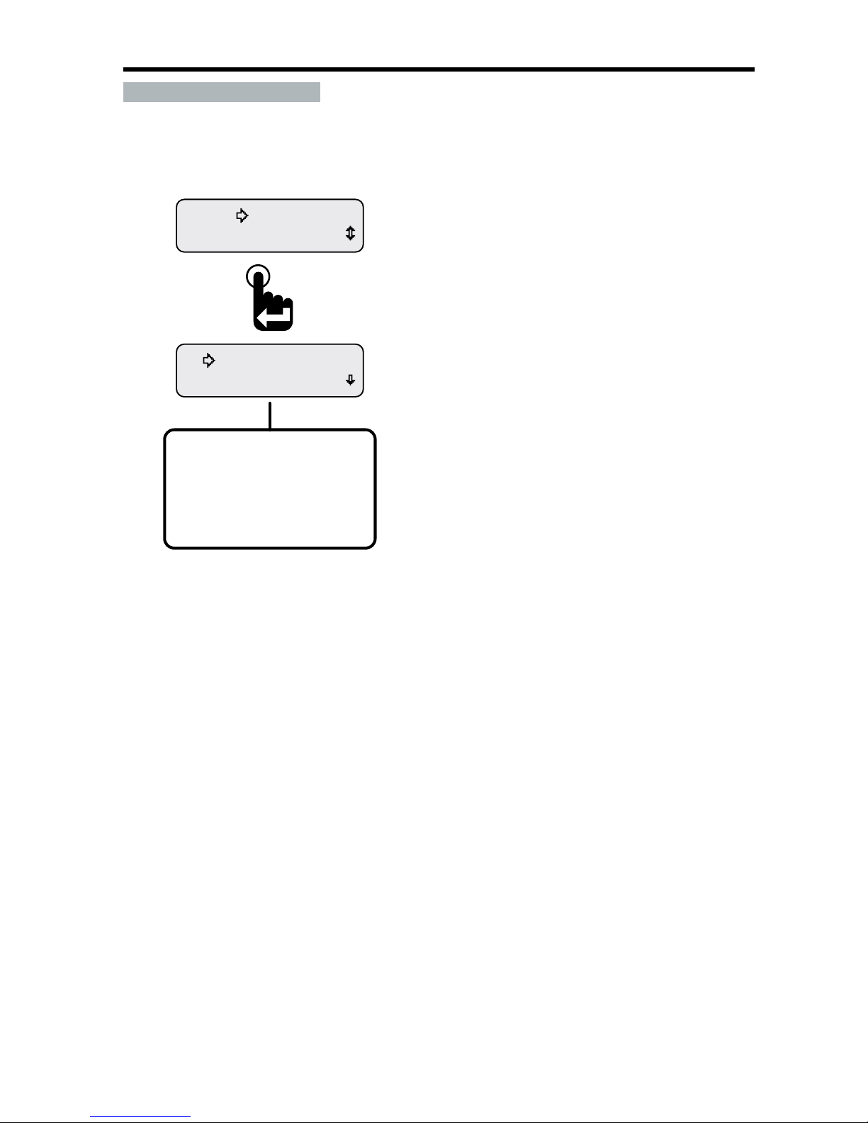
Figure 1-10: Alarms Menu Functions
View Alarms
Alarms-Enabled
Mute Audio Alarm
Alarms
Alarms-Enabled (Disabled)
View Alarms
Edit Alarms
Return
Exit
Alarms Menu Function List.
Note: Pressing the Enter switch toggles between
Alarms Enabled and Alarms-Disabled.
The Alarms menu appears with the selection arrow
cursor next to the Alarms-Enabled or Disabled option.
Scroll down to view all Alarms menu functions.
From the Main Menu, scroll to place the selection
arrow cursor next to the Alarms option.
Press the Enter switch to open Alarms menu.
Alarm Menu function Summary:
Alarms-Enabled - Turns on all set alarms�
Alarms-Disabled - Turns o all set alarms�
View Alarms - Allows users to view all set alarm congurations�
Edit Alarms - Allows users to edit existing alarms, add new alarms or delete existing alarms�
Return - Brings users back to the Alarms option of the Main Menu�
Exit - Brings users back to the last displayed CAN parameter screen
Page 19
13
NexSysLink® 2" Stand-Alone CAN Display Operation Manual SAE J1939
© 2011 Beede Electrical Instrument Co., Inc.
• Enabling/Disabling Alarms
Alarms-Enabled/Disabled turns on or o notication when an alarm condition occurs� This function
does not delete alarms or their settings from the alarm list�
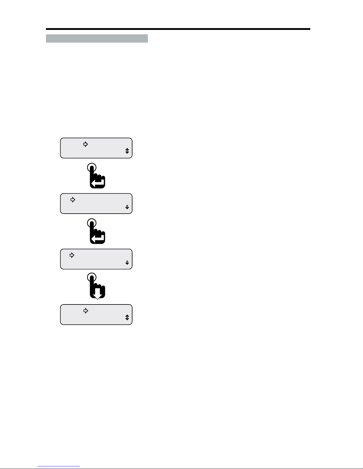
Enabling or disabling alarms is a toggle function� When the Alarm menu is opened the current setting,
enabled or disabled, is shown� To change the current setting, simply press the Enter switch�
To protect against operating the vehicle unaware of potentially damaging conditions, always use
caution when deciding to turn o alarm notication�
Figure 1-11: Enabling/Disabling Alarms
Exit
Return
View Alarms
Alarms-Disabled
View Alarms
Alarms-Enabled
Mute Audio Alarm
Alarms
Scroll down to place the selection arrow cursor next
to the Return option then press the Enter switch
to leave the Alarms menu and return to the Main Menu.
Scroll down to place the selection arrow cursor next
to the Exit option then press the Enter switch to
leave the Alarms menu and view the last displayed
CAN parameter.
After pressing the enter switch, Alarms-Disabled appears.
Pressing the Enter switch a second time will toggle back
to Alarms-Enabled.
Depending upon the previous conguration of the instrument,
the Alarms menu appears with either Alarms-Enabled or
Alarms-Disabled as the current setting.
This screen shows the instrument’s current alarm conguration
as enabled. Pressing the Enter switch toggles to Alarms-Disabled.
From the Main Menu, scroll to place the selection
arrow cursor next to the Alarms option.
Press the Enter switch to open the Alarms menu.
Page 20
14
NexSysLink® 2" Stand-Alone CAN Display Operation Manual SAE J1939
© 2011 Beede Electrical Instrument Co., Inc.
• Viewing Alarms
View Alarms allows users to scroll through all CAN parameters congured for alarm notication�
Users are shown the alarm number, parameter name, measured value for the parameter and the alarm
trigger conditions for the parameter�
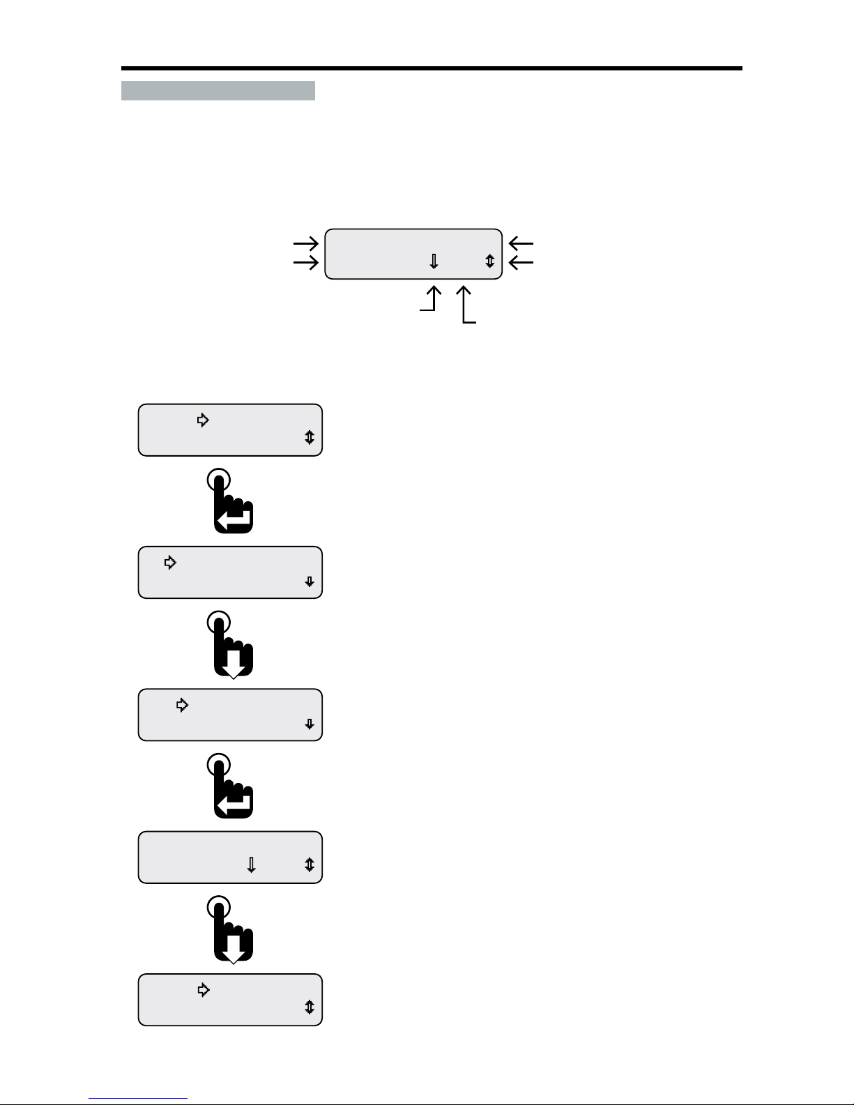
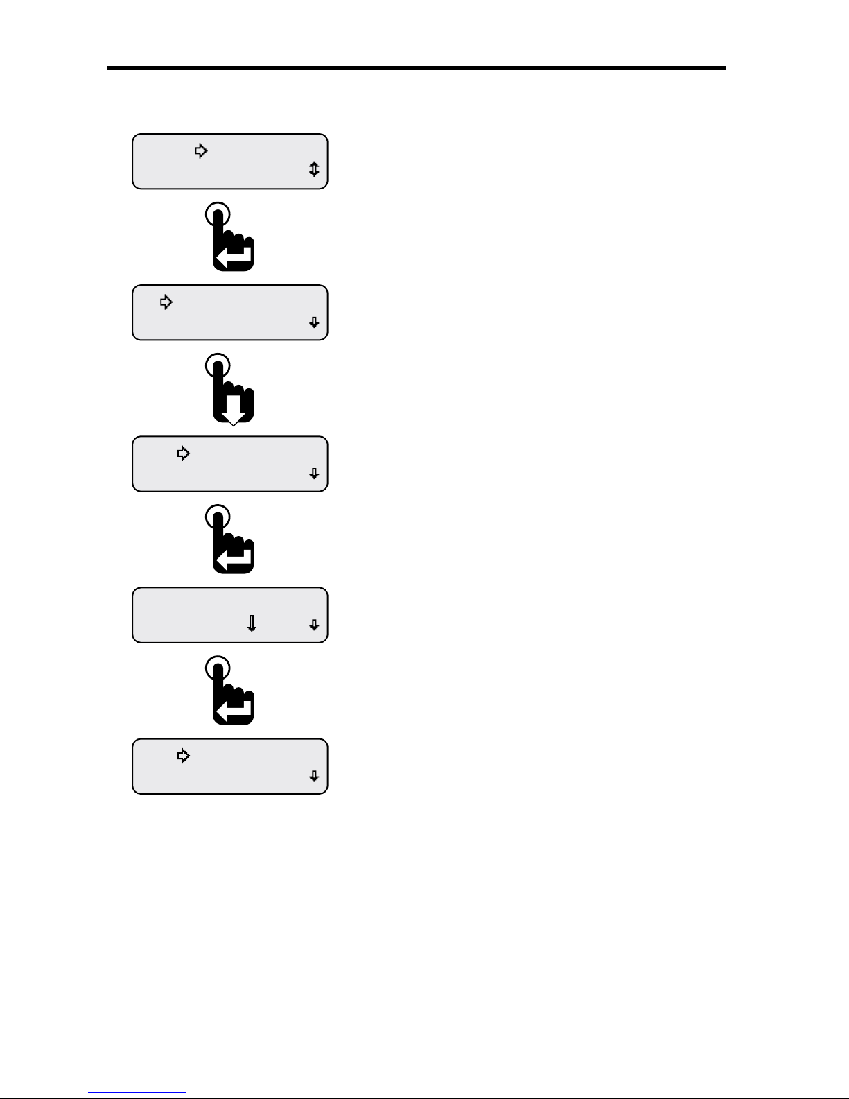
Figure 1-12: Alarm Screen Details
5 10 psi
A1 Eng Oil Pressure
Menu Scroll Icon.
Indicates scroll to view other
alarms or Alarms Menu options.
Parameter Name
Measured Parameter Value.
5 psi shown.
Alarm Number
User set alarm trigger value.
10 psi shown.
Trigger threshold direction indicator.
Lower than indicator shown.
Figure 1-13: Viewing Alarms
Exit
Return
5 10 psi
A1 Eng Oil Pressure
Edit Alarms
View Alarms
View Alarms
Alarms-Enabled
Mute Audio Alarm
Alarms
If no activity is detected for 30 seconds while viewing alarms,
the previously displayed CAN parameter appears.
To manually stop viewing alarms, scroll down to place the
selection arrow cursor next to the Return option then press
the Enter switch to return to the Main Menu or select the Exit
option to view the last displayed CAN parameter.
The rst congured alarm is displayed.
The display shows the alarm number, CAN parameter name
(if implemented), current reading and alarm trigger settings
(Below 10 psi in this example).
Scroll down to view any additional alarms.
With the selection arrow cursor next to the View Alarms option,
press the Enter switch to view any current alarms.
Once in the Alarms menu, scroll down to place the selection
arrow cursor next to the View Alarms option.
From the Main Menu, scroll to place the selection
arrow cursor next to the Alarms option.
Press the Enter switch to open the Alarms menu.
Page 21
15
NexSysLink® 2" Stand-Alone CAN Display Operation Manual SAE J1939
© 2011 Beede Electrical Instrument Co., Inc.
• Alarm Configuration
When adding a new alarm parameter or editing an existing alarm parameter with the Edit Alarms
option, users must set the following:
1� The CAN parameter to use�
2� The trigger threshold direction (Higher or Lower than alarm trigger value)�
3� The alarm trigger value�
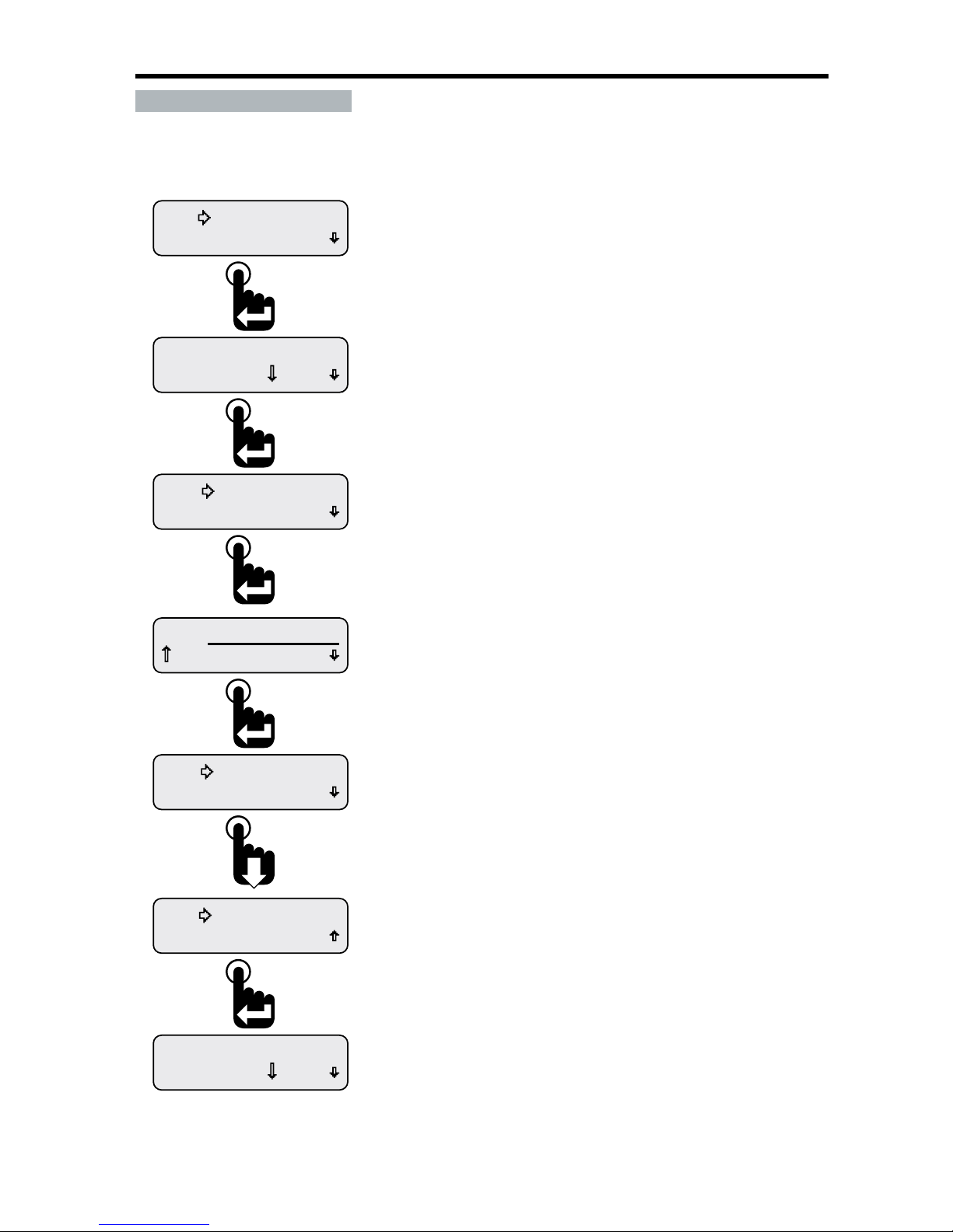
Figure 1-14: Add & Edit Alarm CAN Parameter Screen Details
10.0 V
A1 Alternator Volts
Menu/Value Scroll Icon.
Indicates scroll to view other
parameters, change direction
or value.
CAN Parameter Name
Higher/Lower Indicator
Alarm Number
Alarm Trigger Value
Higher than threshold indicator.
Alarm notication occurs
when measured parameter
is higher than trigger value.
Lower than threshold indicator.
Alarm notication occurs
when measured parameter
is lower than trigger value.
To select a CAN parameter, scroll through the parameter list with the Up and Down switches until the
desired parameter appears� Press the Enter switch to add the parameter to the alarm list�
After selecting a parameter, the blinking bar cursor appears under the Higher/Lower than arrow icon�
Users must choose if the alarm notication will occur when the actual parameter value is either higher
or lower than the desired trigger value� Pressing either the Up or Down switch toggles the indicator
between the higher than arrow (pointing up) and lower than arrow (pointing down)� Press the Enter
switch to accept direction of the arrow icon�
Once higher or lower is chosen, the blinking bar cursor moves to the alarm notication trigger value�
The units of this value change depending on the type of parameter chosen� Use the Up or Down
switches to change the value then press the Enter switch to accept the displayed value�
After conguring all the alarm parameters, users can choose to save or discard the alarm conguration�
Page 22
16
NexSysLink® 2" Stand-Alone CAN Display Operation Manual SAE J1939
© 2011 Beede Electrical Instrument Co., Inc.
• Adding an Alarm or Alarms
The Edit Alarms function is used to add CAN parameters for alarm notication�
Users may set up to 15 parameters for alarm notication�
The Edit Alarms menu screens dier if no alarms are set as compared to when previously congured
alarms exist� If no previously congured alarms exist, the Add Alarm menu option appears after
selecting Edit Alarms� If previously congured alarms exist, the congured alarms appear before the
Add Alarm menu option� To add an additional alarm when previously alarms exist, users must scroll
down thru all the previously congured alarms before reaching the Add Alarm menu option�
Figure 1-15: Menu Prompt Sequence with No Congured Alarms
Return
Add Alarm
Return
Edit Alarms
View Alarms
Alarms-Enabled
Mute Audio Alarm
Alarms
When no alarms exist, selecting Edit Alarms returns two
menu options, Add Alarm and Return.
Press the Enter switch to begin adding a CAN parameter
for alarm notication or select Return to bring back
the Edit Alarms menu option.
With the selection arrow cursor next to the Edit Alarms
option, press the Enter switch to begin editing alarms.
The Alarms Menu appears with the selection arrow
cursor next to the Alarms-Enabled or Disabled option.
Scroll down to place selection arrow cursor next to the
Edit Alarms option.
From the Main Menu, scroll to place the selection
arrow cursor next to the Alarms option.
Press the Enter switch to open Alarms Menu.
Page 23
17
NexSysLink® 2" Stand-Alone CAN Display Operation Manual SAE J1939
© 2011 Beede Electrical Instrument Co., Inc.
Figure 1-16: Menu Prompt Sequence with Previously Congured Alarms
Return
Add Alarm
Change? 10.0 V
A1 Alternator Volts
Return
Edit Alarms
View Alarms
Alarms-Enabled
Mute Audio Alarm
Alarms
Press the Enter switch to add a new alarm or select
Return to bring back the Edit Alarms menu option.
When a previously congured alarm or alarms exists,
they will appear after selecting Edit Alarms.
Scroll down thru all the previously congured alarms
to reach the Add Alarm menu function.
With the selection arrow cursor next to the Edit Alarms
option, press the Enter switch to begin editing alarms.
The Alarm menu appears with the selection arrow
cursor next to the Alarms-Enabled or Disabled option.
Scroll down to place selection arrow cursor next to
Edit Alarms option.
From the Main Menu, scroll to place the selection
arrow cursor next to the Alarms option.
Press the Enter switch to open Alarms Menu.
Page 24
18
NexSysLink® 2" Stand-Alone CAN Display Operation Manual SAE J1939
© 2011 Beede Electrical Instrument Co., Inc.
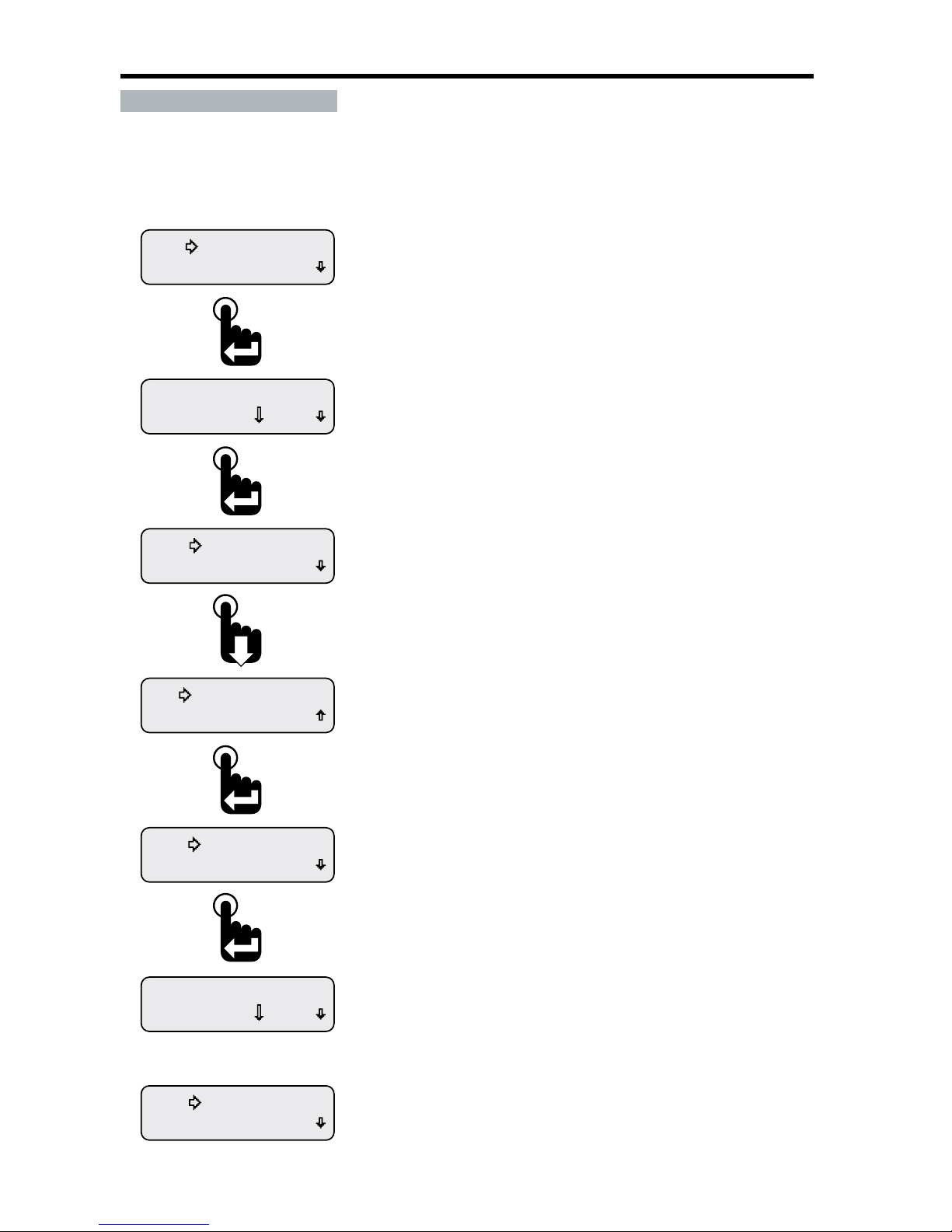
• Editing Alarms
The Edit Alarms function is used to change an alarms existing CAN parameter, higher/lower than
threshold indicator or trigger value�
Figure 1-17: Editing an Alarm
Change? 10.0 V
A1 Alternator Volts
Save Alarm
Save Alarm
No Change
0.0 V
A1 Alternator Volts
Delete Alarm
Edit Alarm
Change? 10.0 V
A1 Alternator Volts
Return
Edit Alarms
After choosing to either save or discard alarm changes, the same
alarm conguration screen appears to allow users to re-edit the
alarm if necessary.
Once the displayed alarm conguration is acceptable, press the
Down switch to scroll to the next alarm if one is congured or to the
Add Alarm and Return menu options.
With the selection arrow cursor next to the Save Alarm option,
press the Enter switch to save alarm changes.
Pressing the Enter switch after accepting the existing or edited
trigger value opens the save options menu choices.
To discard changes to the alarm, press the Enter switch to select
No Change. Otherwise, scroll down to place the selection arrow
cursor next to the Save Alarm option.
The alarms conguration screen appears with the blinking bar
cursor beneath the CAN parameter name.
Step through and edit the parameter name, threshold direction
and trigger value as desired using the Up and Down switches.
Pressing the Enter switch accepts and sets any changes.
After choosing an alarm to change, the selection arrow cursor
appears next to the Edit Alarm, option.
Press the Enter switch to begin editing the chosen alarm.
Pressing the Enter switch displays the rst previously congured
CAN parameter for alarm notication, A1.
The prompt “Change?” appears in the lower left corner of the display.
Press the Enter switch to accept the prompt to change/edit the
the displayed alarm, A1.
If more than one alarm exists, scroll down to display the desired
alarm then press the Enter switch to change/edit it.
From the Alarms Menu place the selection arrow cursor
next to the Edit Alarms option, Main Menu-Alarms-Edit Alarms,
then press the Enter switch to begin editing alarms.
Page 25
19
NexSysLink® 2" Stand-Alone CAN Display Operation Manual SAE J1939
© 2011 Beede Electrical Instrument Co., Inc.
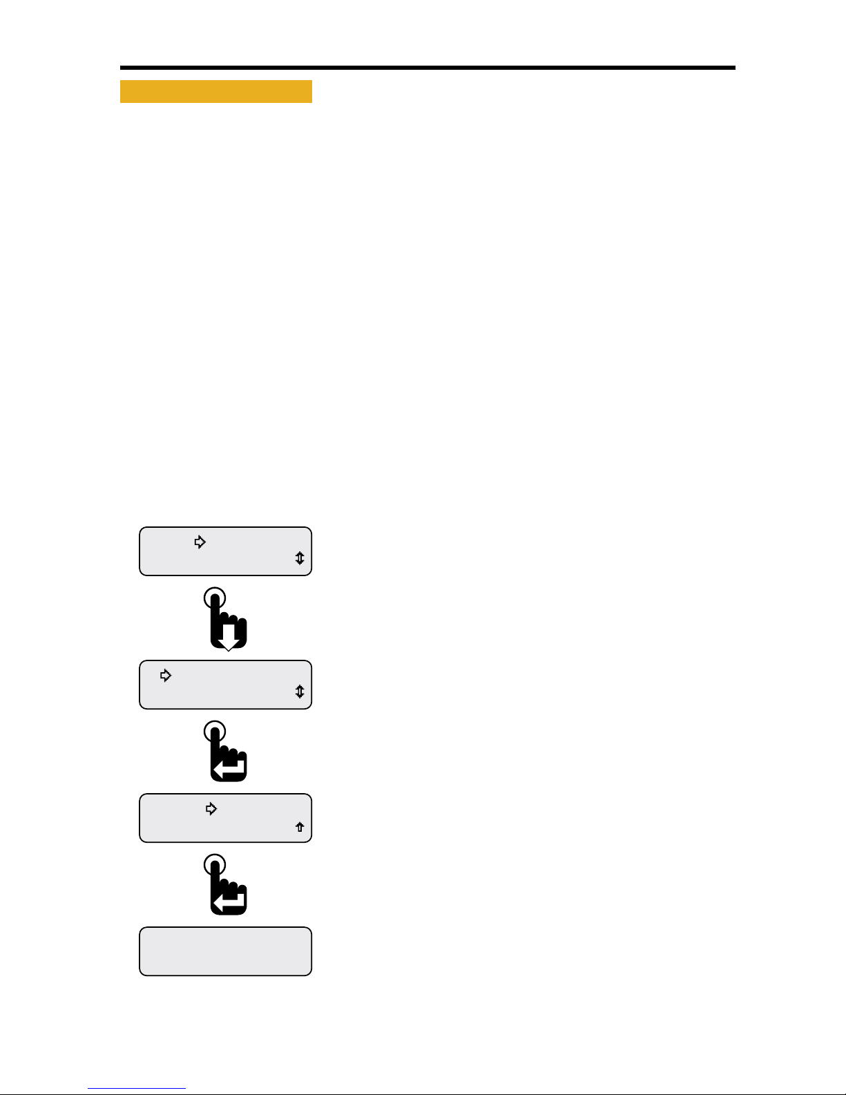
• Deleting Alarms
The Edit Alarms function is also used to delete existing alarms�
Figure 1-18: Deleting an Alarm
Return
Add Alarm
Change? 10.0 V
A1 Baery Volts
Confirm Delete
No Change
Delete Alarm
Delete Alarm
Edit Alarm
Change? 10.0 V
A1 Alternator Volts
Return
Edit Alarms
Or
If No Change is selected above, the previously displayed
Alarm conguration screen appears.
If Conrm Delete is selected, the next congured alarm appears.
If no other alarms were congured, the Add Alarm and Return
menu options appear.
After selecting Delete Alarm, users must either cancel the delete
request by selecting No Change or conrm the deletion by selecting
Conrm Delete.
With the selection arrow cursor next to the Delete Alarm option,
press the Enter switch.
After choosing the displayed alarm to delete, the selection arrow
cursor appears next to the Edit Alarm option.
Press the Down switch to place the selection arrow cursor next to the
Delete Alarm option then press the Enter switch.
Pressing the Enter switch displays the rst previously congured
CAN parameter for alarm notication, A1.
The prompt “Change?” appears in the lower left corner of the display.
To delete the displayed alarm conguration, press the Enter switch
to accept the prompt to change the alarm. Otherwise, press the
down switch until the desired alarm to delete appears on the
display then press the Enter switch to accept the change prompt.
From the Alarms Menu place the selection arrow cursor
next to the Edit Alarms option, Main Menu-Alarms-Edit Alarms,
then press the Enter switch to begin editing alarms.
Page 26
20
NexSysLink® 2" Stand-Alone CAN Display Operation Manual SAE J1939
© 2011 Beede Electrical Instrument Co., Inc.
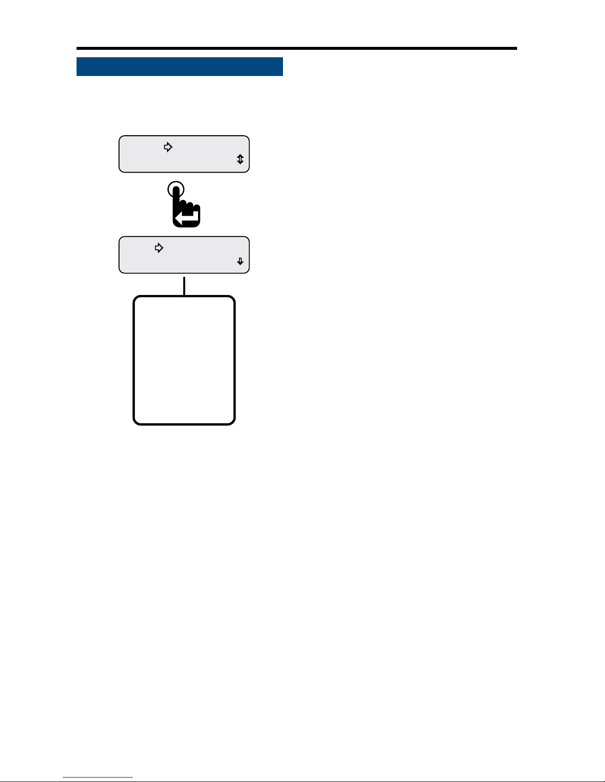
• Mute
The instrument is equipped with an internal audible device to alert users when a Fault, Warning or
Alarm condition occurs� Pressing the Enter switch after a Fault, Warning or Alarm condition occurs
either temporarily or permanently mutes the audible device for that condition depending upon the
setting of Mute Audio Alarm, Main Menu-Mute Audio Alarm�
Note: Regardless of the Mute Audio Alarm setting, the rst occurrence of a Fault, Warning or Alarm
condition always activates the audio alarm� Subsequent occurrences of the same Fault, Warning or
Alarm condition is controlled by the Mute Audio Alarm setting�
If an external audible device is connected to the switched output pin 3 of the connector, the device is
muted as well� For muting external devices, see "Alarm Output" on page 32�
Mute Audio Alarm - Permanent setting turns o the audible device for subsequent occurrences of the
specic Fault, Warning or Alarm�
Mute Audio Alarm - Temporary setting disables the audible device for twenty seconds�
Faults are muted for 20 seconds� Warnings and Alarms are muted for 2 minutes� Faults are muted
for a shorter period of time because they are considered critical conditions that require immediate
attention� A Fault condition sounds a steady audible tone while Warning and Alarms conditions sound
an intermittent audible tone�
Figure 1-19: Muting Faults, Warnings & Alarms
Engine Hours
1049.3
Exit
Setup
Mute-Temporary
Mute Audio Alarm
Alarms
Last displayed CAN parameter appears.
Engine Hours parameter shown as an example only.
After setting the mute status, scroll down to the Exit option then
press the Enter switch to return to the last displayed CAN parameter
or simply wait 30 seconds for the last displayed CAN parameter
to appear.
When the selection arrow cursor is placed next to the
Mute Audio Alarm option, the name changes to Mute and the
current state, i.e., Mute-Temporary or Mute-Permanent.
Pressing the Enter switch toggles between the two settings.
The setting is automatically saved once changed.
From the Main Menu, scroll to place the selection arrow cursor
next to the Mute Audio Alarm option, Main Menu-Mute Audio Alarm.
Page 27
21
NexSysLink® 2" Stand-Alone CAN Display Operation Manual SAE J1939
© 2011 Beede Electrical Instrument Co., Inc.
• Setup Menu
The Setup Menu contains all the functions necessary to congure the instrument to satisfy user
preferences and application requirements� This section of the manual describes those functions�
Figure 1-20: Setup Menu Functions
Units
Backlight
Informaon
Setup
Setup Menu Function List.
Backlight
Units
Popup
Display
Trip Mode
Alarm Output
Return
Exit
The Setup menu appears with the selection arrow
cursor next to the Backlight option.
Scroll down to view all Setup menu functions.
From the Main Menu, scroll to place the selection
arrow cursor next to the Setup option.
Press the Enter switch to view Setup functions.
Setup Menu function summary:
Backlight - Sets intensity of instrument illumination�
Units - Sets display units to English or SI-Metric�
Popup - Activates notication screen for Faults, Warnings and Alarms�
Display - Sets either 1 or 2 parameter display mode, LCD contrast and positive or negative image mode�
Trip Mode - Determines if maintenance hours or trip miles displays as the rst item of the Main Menu�
Alarm Output - Turns o (mutes) the output for audible devices�
Return - Brings users back to Main Menu-Setup�
Exit - Leaves the menu to show the last displayed CAN parameter�
Page 28
22
NexSysLink® 2" Stand-Alone CAN Display Operation Manual SAE J1939
© 2011 Beede Electrical Instrument Co., Inc.
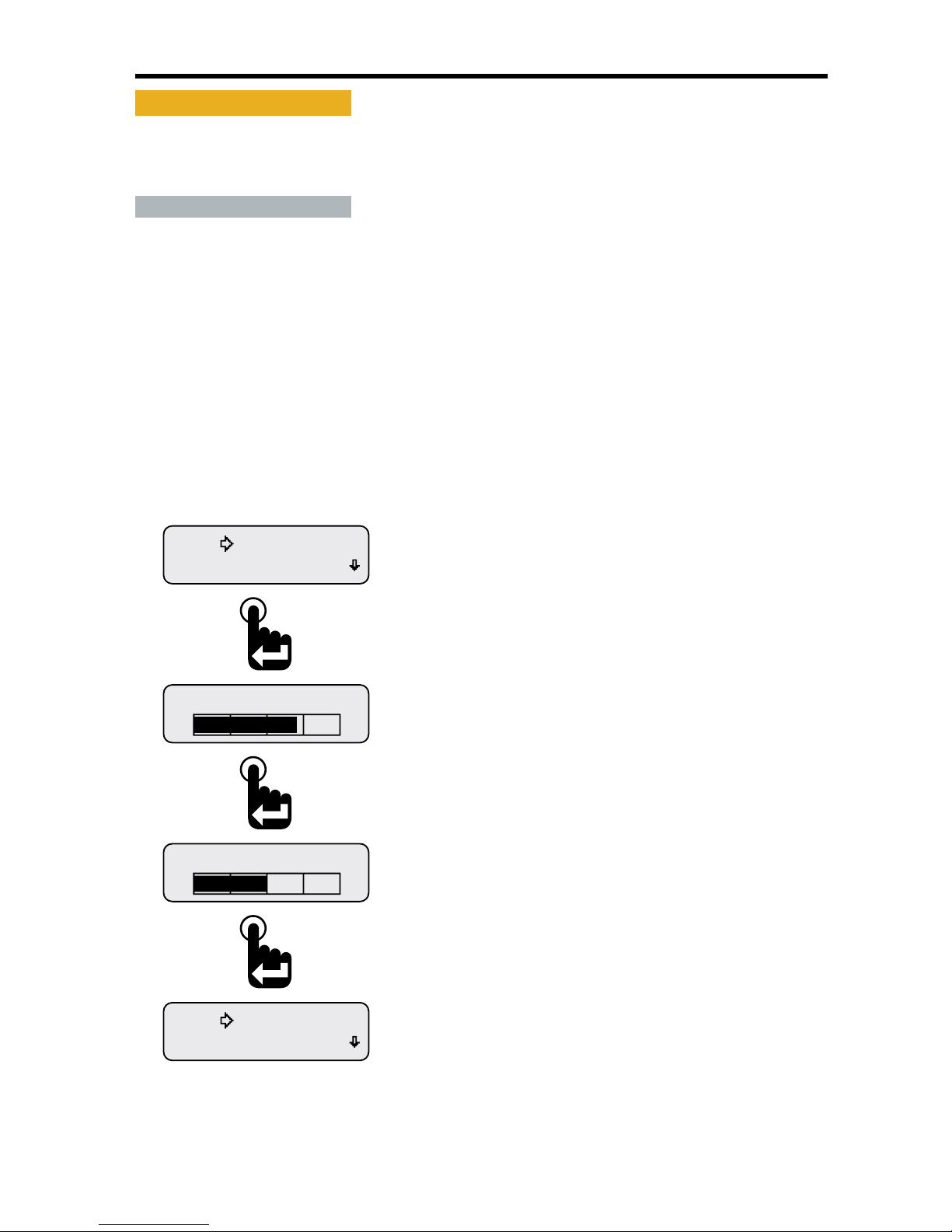
• Backlight
The instrument oers two levels of illumination control; external lamp switch on and lamp switch o�
Backlight intensity is set using the Backlight option from the Setup Menu, Main Menu-Setup-Backlight�
Backlight intensity values range from 0 or o to 100% or maximum by increments of 10%�
• Lamp On & Lamp Off
Lamp On: The Lamp On function sets the backlight illumination brightness when pin 4 of the
instrument's 6 pin connector is wired to an external lamp switch and that switch is turned on�
Lamp O: The Lamp O function sets the backlight illumination brightness when no external lamp
switch is used or when an external lamp switch is wired to pin 4 of the instruments 6 pin connector
and the lamp switch is turned o� This feature allows users to turn on and control the instruments
backlighting independent of the vehicle's or equipment's light switch�
Note: Standard factory hardware conguration for the instrument uses Pin 4 of the 6 pin connector
to connect to an external lamp switch� Some factory congured instruments use pin 4 for serial data
communication to Beede NexSysLink® instruments� See "Stand-Alone and Master Node Congurations"
on page iv for more information�
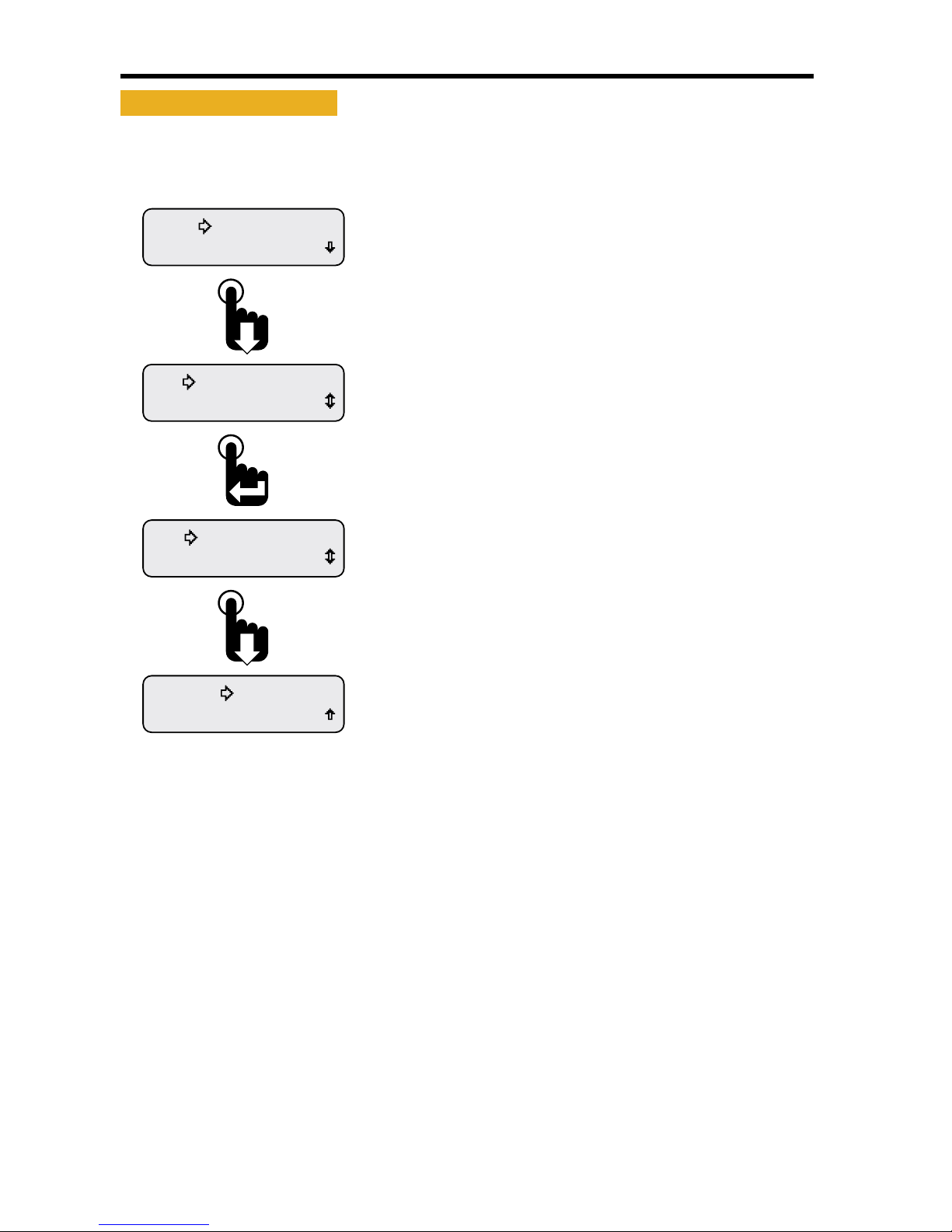
Figure 1-21: Setting Backlight Intensity
Units
Backlight
Lamp Off 50%
Lamp On 70%
Units
Backlight
Once the Lamp O backlight intensity is set, the Backlight
option of the Setup menu appears.
Scroll down to exit the Setup Menu or wait 30 seconds for
the last displayed CAN parameter to appear.
After setting the Lamp On backlight intensity, the Lamp O
backlight intensity screen appears.
Use the Up and Down switches to increase or decrease
the Lamp O backlight intensity.
Press the Enter switch to accept the value.
Lamp On backlight intensity bar graph appears.
Use the Up and Down switches to increase or decrease
the Lamp On backlight intensity.
Press the Enter switch to accept the value.
From the Setup Menu place the selection arrow cursor next to
Backlight, Main Menu-Setup-Backlight, then press the
Enter switch to begin adjusting the LCD backlight intensity.
Page 29
23
NexSysLink® 2" Stand-Alone CAN Display Operation Manual SAE J1939
© 2011 Beede Electrical Instrument Co., Inc.
• Setting Units
Users may select to display CAN parameters in either English or SI-Metric units�
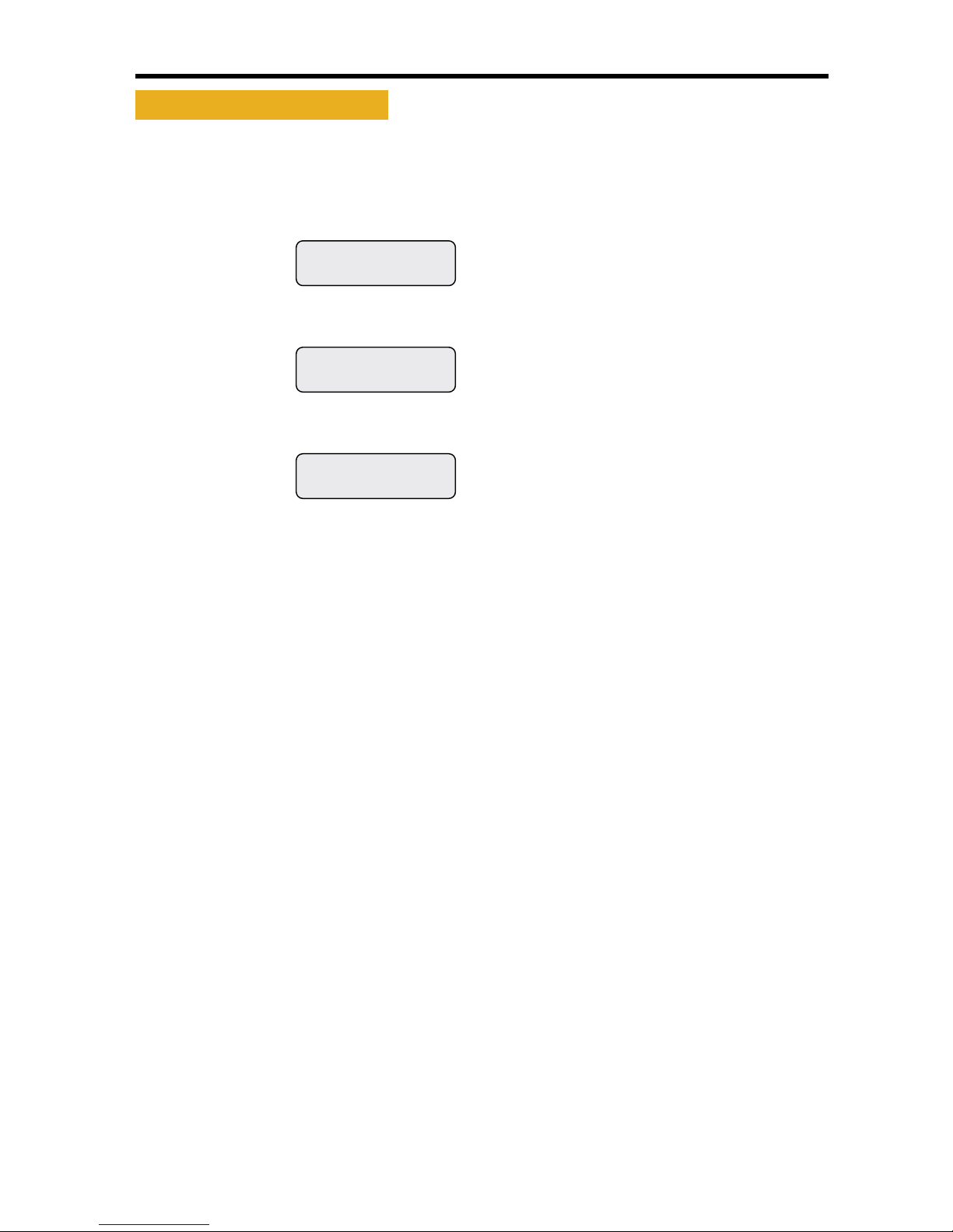
Figure 1-22: Setting Units
Exit
Popup
Units-Metric
Popup
Units-English
Units
Backlight
Scroll down to the Exit option and press the Enter switch or
wait 30 seconds for the last displayed CAN parameter to appear.
Pressing the Enter switch toggles the units to Metric.
Press the Enter switch to toggle the units back to English.
When the selection arrow cursor is placed next to the
Units option, the name changes to Units and the current
setting, i.e., Units-English or Units-Metric.
Pressing the Enter switch toggles between the two settings.
The setting is automatically saved once changed.
From the Setup menu, scroll to place the selection arrow
cursor next to the Units option, Main Menu-Setup-Units.
Page 30
24
NexSysLink® 2" Stand-Alone CAN Display Operation Manual SAE J1939
© 2011 Beede Electrical Instrument Co., Inc.
• Popups Notification Screens
Turning on popups provide a highly visible alert screen when a system Fault, Warning or Alarm occurs�
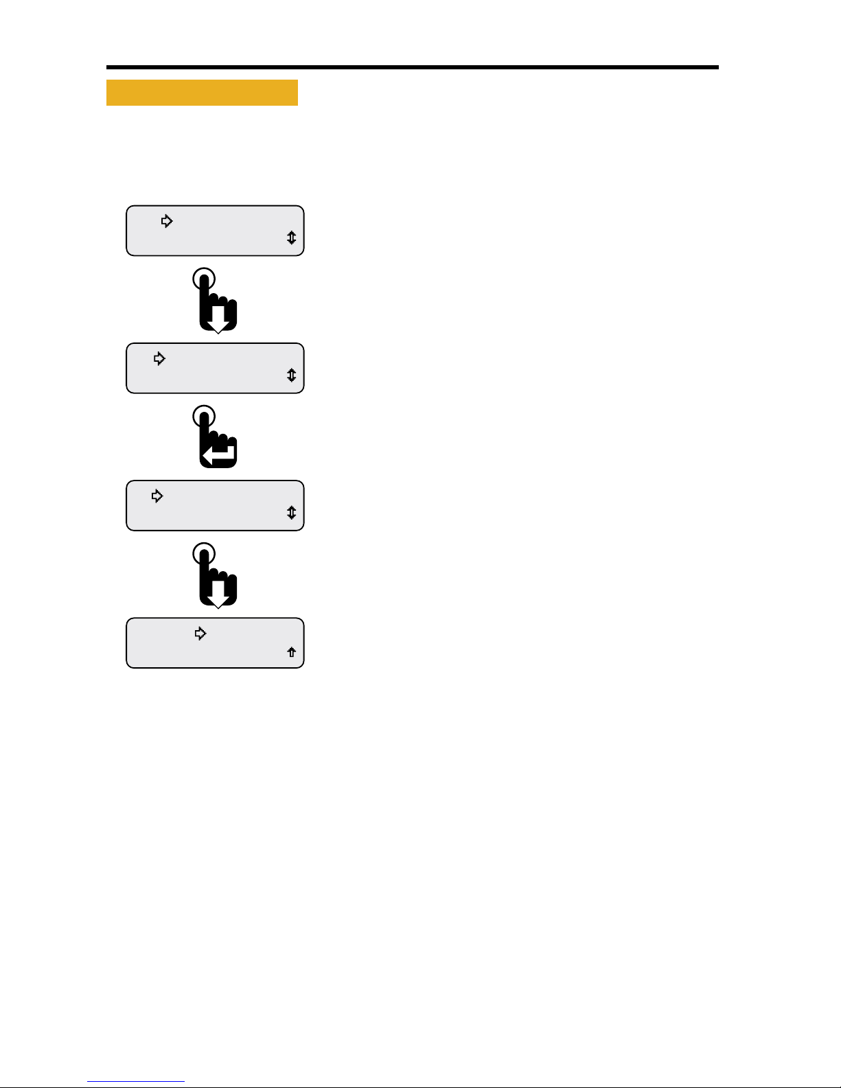
Figure 1-23: Popup Fault, Warning & Alarm Screens
ALARM
WARNING
FAULT
Alarm Notication Screen
Warning Notication Screen
Fault Notication Screen
Pressing the Enter switch clears the
notication screens.
Pressing the Up or Down switch
displays the Fault, Warning or Alarm
condition detail information screen.
Fault, Warning and Alarm popup screens remain displayed until acknowledged by pressing the Enter
switch� Pressing the Enter switch returns the last displayed CAN parameter prior to the occurrence of
the Fault, Warning or Alarm condition�
For Faults and Warnings, the Fault LED and Warning LED remain illuminated after pressing the Enter
switch to acknowledge and clear the notication screen�
After pressing the Enter switch for Alarms, a blinking "bell" icon appears in the upper left corner of the
CAN parameter display screen to indicate an alarm condition exists�
Pressing the Up or Down switch when a notication screen appears brings up the Fault, Warning or
Alarm detail information display�
Note: If the condition that caused the Fault, Warning or Alarm clears, the notication screens and bell
icon disappears and the alert LEDs turn o�
Page 31
25
NexSysLink® 2" Stand-Alone CAN Display Operation Manual SAE J1939
© 2011 Beede Electrical Instrument Co., Inc.
• Setting Popups
Enabling popups allows the Fault, Warning and Alarm screens to appear when a when a System Fault,
Warning or Alarm condition occurs�
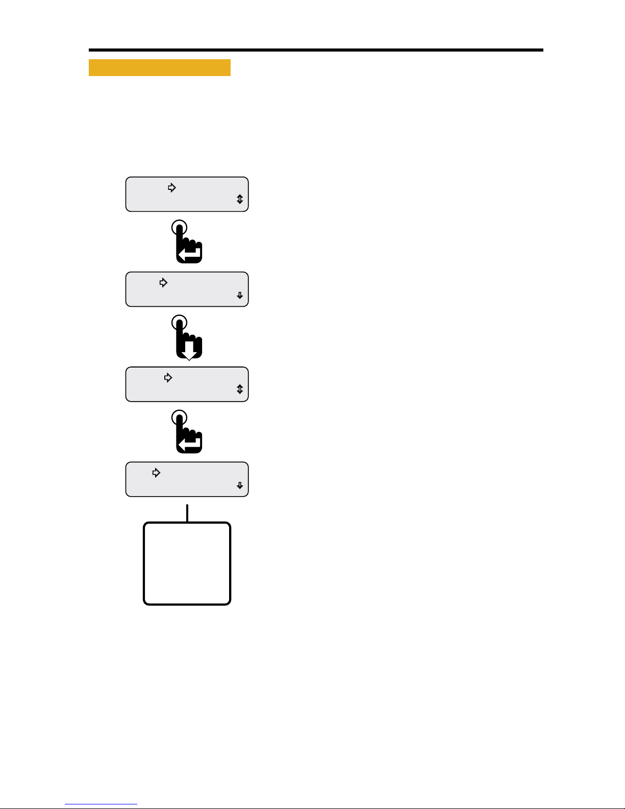
Figure 1-24: Setting Popup Status
Exit
Display
Popup-Disabled
Display
Popup-Enabled
Popup
Units-English
Scroll down to the Exit option and press the Enter switch or
wait 30 seconds for the last displayed CAN parameter to appear.
Pressing the Enter switch toggles the popup setting to
disabled. Press the Enter switch to toggle the units back
to enabled.
When the selection arrow cursor is placed next to the
Popup option, the name changes to Popup and the current
setting, i.e., Popup-Enabled or Popup-Disabled.
Pressing the Enter switch toggles between the two settings.
The setting is automatically saved once changed.
From the Setup menu, scroll to place the selection arrow
cursor next to the Popup option, Main Menu-Setup-Popup.
Page 32
26
NexSysLink® 2" Stand-Alone CAN Display Operation Manual SAE J1939
© 2011 Beede Electrical Instrument Co., Inc.
• Display
The Display Menu functions provide users the ability to congure the LCD� Options for conguring
the display include either 1 or 2 parameter display mode, LCD contrast and positive or negative image
mode� Each function is detailed in the following pages�
Figure 1-25: Display Menu
Contrast
1-Parameter
Trip Mode
Display
Units
Backlight
Informaon
Setup
Display Menu Function List.
*1- Parameter
Contrast
Video Mode
Return
Exit
* Either Maintenance Hours or
Vehicle Trip appears as the rst
Main Menu function depending
upon the Main Menu-Setup-Trip Mode
conguration.
Main Menu-Setup-Trip-Hours
displays Maintenance Hours.
Main Menu-Setup-Trip-Distance
displays Vehicle Trip.
The Display Menu appears with the selection arrow
cursor next to either the 1-Parameter or 2-Parameter option.
Scroll down to view all Display Menu functions.
Scroll down to place the selection arrow cursor next
to the Display option then press the Enter Switch.
The Setup Menu appears with the selection arrow
cursor next to the Backlight option.
From the Main Menu, scroll to place the selection
arrow cursor next to the Setup option.
Press the Enter switch to view setup functions.
Page 33
27
NexSysLink® 2" Stand-Alone CAN Display Operation Manual SAE J1939
© 2011 Beede Electrical Instrument Co., Inc.
• 1 or 2 Parameter Display
Users can set whether 1 or 2 CAN parameters appear on the LCD screen�
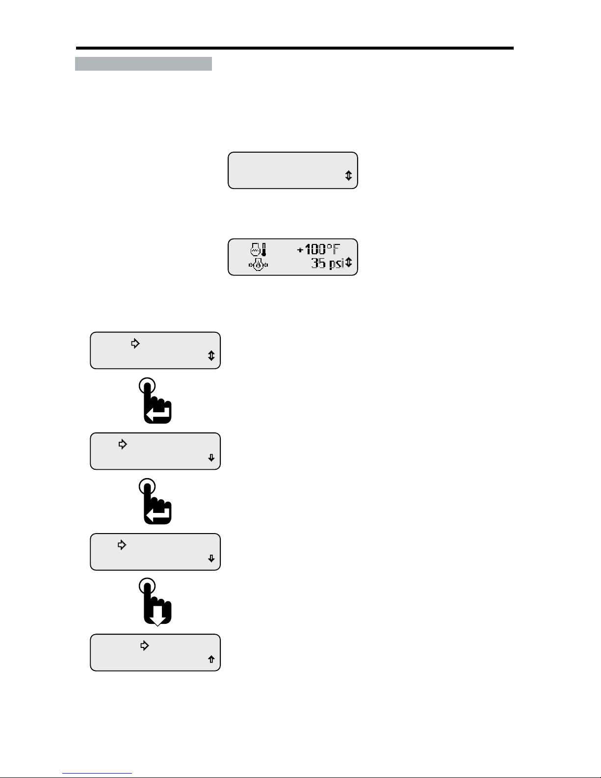
Figure 1-26: 1 and 2 CAN Parameter Display Formats
Eng Oil Pressure
35 PSI
1- Parameter Display Format
2- Parameter Display Format
Figure 1-27: Setting 1 or 2 Parameter Display Lines
Exit
Contrast
2-Parameter
Contrast
1-Parameter
Trip Mode
Display
Scroll down to the Exit option and press the Enter switch or
wait 30 seconds for last displayed CAN parameter to appear.
Pressing the Enter switch toggles the paramater display mode
to two 2-Parameter.
When the Display Menu opens, the selection arrow appears
next to the current parameter display mode setting,
i.e., 1-Parameter or 2-Parameter.
Pressing the Enter switch toggles between the two settings.
The setting is automatically saved once changed.
From the Setup Menu place the selection arrow cursor next to
the Display option, Main Menu-Setup-Display, then press
the Enter switch to view the Display Menu functions.
Page 34
28
NexSysLink® 2" Stand-Alone CAN Display Operation Manual SAE J1939
© 2011 Beede Electrical Instrument Co., Inc.
• Set Contrast
Contrast sets the dierence between the white and black colors of the LCD�
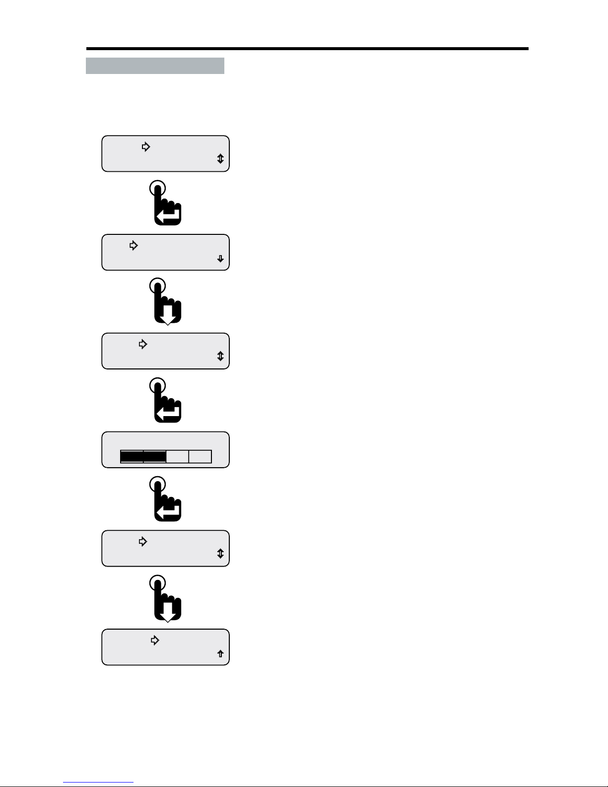
Figure 1-28: Setting LCD Contrast
Exit
Video Mode
Contrast
Contrast 50%
Video Mode
Contrast
Contrast
1-Parameter
Trip Mode
Display
Scroll down to the Exit option and press the Enter switch or
wait 30 seconds for the last displayed CAN parameter to appear.
After setting the contrast value, the selection arrow cursor
appears next to the Contrast option of the Display Menu,
Main Menu-Setup-Display-Contrast.
The contrast adjustment screen appears.
Use the Up and Down switches to increase or decrease the
contrast percent. Press the Enter switch to accept the
displayed contrast value.
With the selection arrow cursor next to the Contrast option,
press the Enter switch to open the contrast adjustment
screen.
The rst two Display Menu functions appear. Scroll to place
the selection arrow cursor next to the Contrast option.
From the Setup Menu place the selection arrow cursor next to
the Display option, Main Menu-Setup-Display, then press
the Enter switch to view the Display menu functions.
Page 35
29
NexSysLink® 2" Stand-Alone CAN Display Operation Manual SAE J1939
© 2011 Beede Electrical Instrument Co., Inc.
• Video Mode Formats
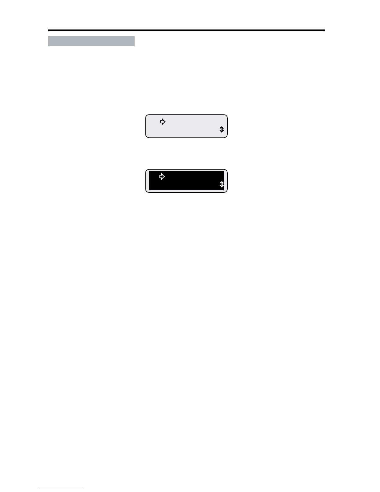
Setting the video mode changes the color scheme of the LCD from white graphics on a black
background (Normal) to black graphics on a white background (Reverse)�
Figure 1-29: Video Mode Formats
Return
Video-Reverse
Return
Video-Normal
LCD Reverse Video Mode
LCD Normal Video Mode
Page 36
30
NexSysLink® 2" Stand-Alone CAN Display Operation Manual SAE J1939
© 2011 Beede Electrical Instrument Co., Inc.
• Set Video
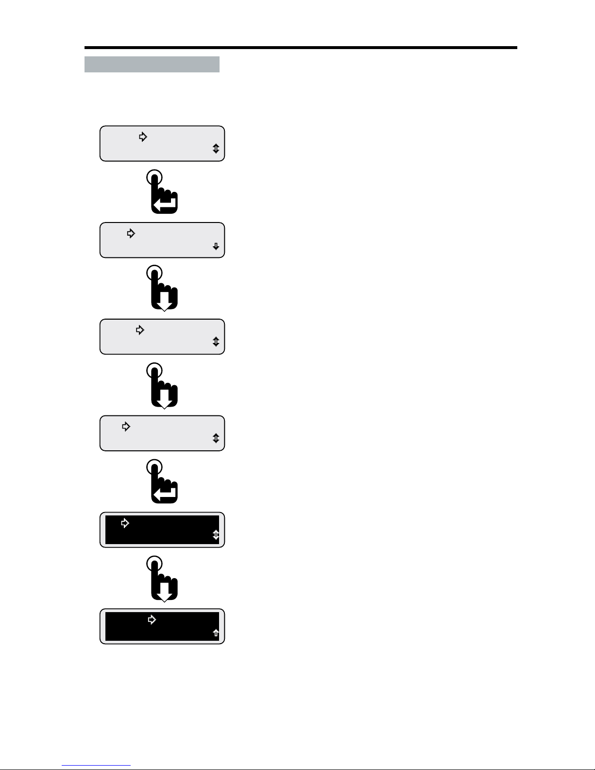
The menu sequence below shows how to set the video mode to either normal or reverse�
Figure 1-30: Setting LCD Background Color Scheme (Video Mode)
Exit
Return
Video-Reverse
Return
Video-Normal
Video Mode
Contrast
Contrast
1-Parameter
Trip Mode
Display
Scroll down to the Exit option and press the Enter switch or
wait 30 seconds for the last displayed CAN parameter to appear.
Pressing the Enter switch toggled the video mode to the
reverse setting.
The setting is automatically saved once changed.
When the selection arrow cursor is placed next to the
Video-Mode option, the name changes to the current video
display mode, i.e., Video-Normal or Video-Reverse.
Pressing the Enter switch toggles between the two settings.
The setting is automatically saved once changed.
Screen shows Video Mode function prior to placing the
selection arrow cursor next to the function.
Continue to press the Down switch to place the selection
arrow cursor next to the Video Mode function.
The rst two Display Menu functions appear. Scroll to place
the selection arrow cursor next to the Video Mode option.
From the Setup Menu place the selection arrow cursor next to
the Display option, Main Menu-Setup-Display, then press
the Enter switch to view the Display Menu functions.
Page 37
31
NexSysLink® 2" Stand-Alone CAN Display Operation Manual SAE J1939
© 2011 Beede Electrical Instrument Co., Inc.
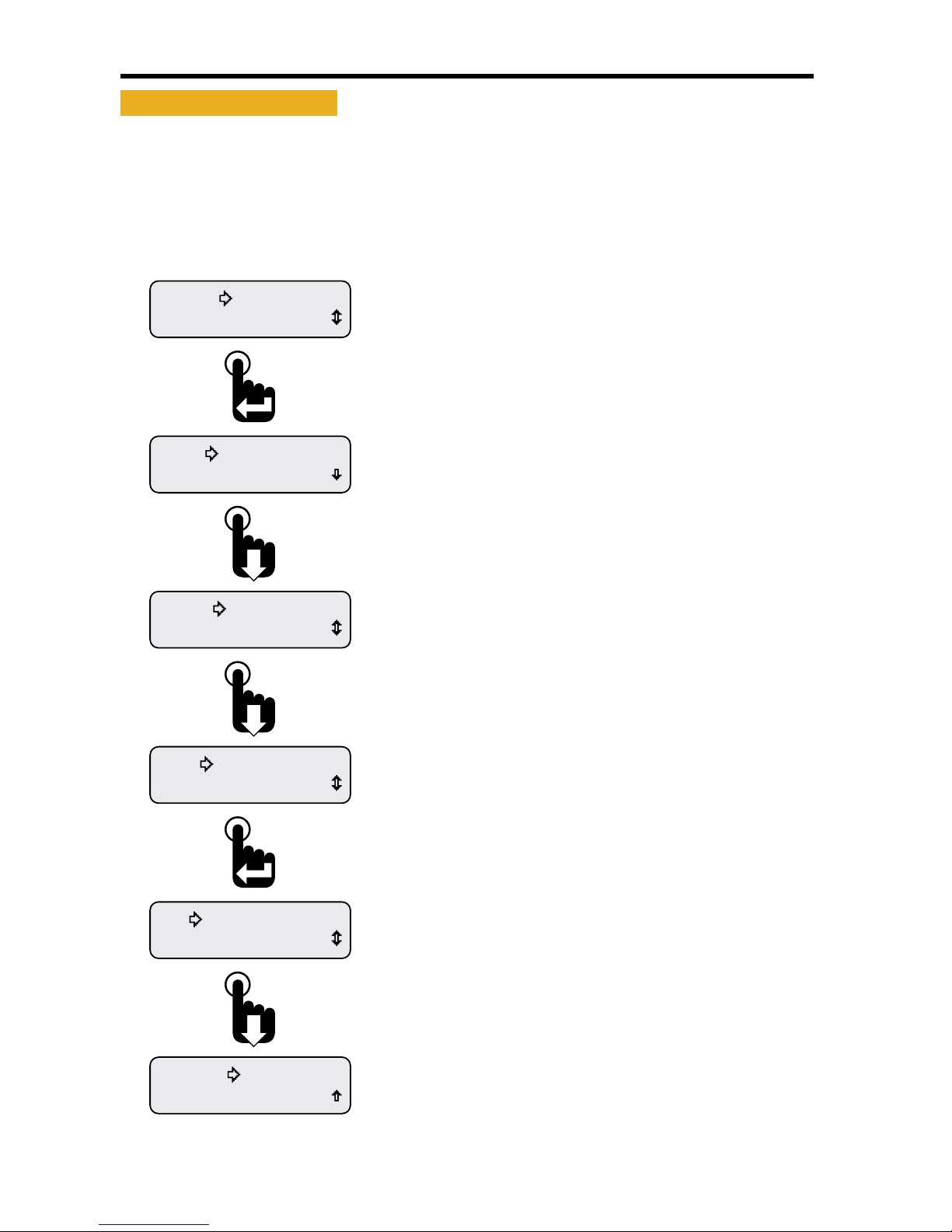
• Trip Mode
The Trip mode setting determines whether distance or hours appear as the rst item upon entering the
Main Menu�
The decision to set the Trip Mode function to either hours or distance depends upon which of the two
parameters is viewed more frequently in the application�
Figure 1-31: Setting Hours or Miles for Main Menu Display
Exit
Alarm Output
Trip-Distance
Alarm Output
Trip-Hours
Trip Mode
Display
Units
Backlight
Informaon
Setup
Scroll down to the Exit option and press the Enter switch or
wait 30 seconds for last displayed CAN parameter to appear.
Pressing the Enter switch toggled the Trip Mode setting to
the distance setting.
The setting is automatically saved once changed.
When the selection arrow cursor is placed next to the
Trip Mode option, the name changes to the current Trip Mode
setting, i.e., Trip-Hours or Trip-Distance.
Pressing the Enter switch toggles between the two settings.
The setting is automatically saved once changed.
Screen shows Trip Mode function prior to placing the
selection arrow cursor next to the function.
Continue to press the Down switch to place the selection
arrow cursor next to the Trip Mode function.
The Setup Menu appears with the selection arrow cursor
next to the Backlight option.
Scroll down to place the selection arrow cursor next
to the Trip Mode option.
From the Main Menu, scroll to place the selection arrow cursor
next to the Setup option.
Press the Enter switch to view the Setup Menu functions.
Page 38
32
NexSysLink® 2" Stand-Alone CAN Display Operation Manual SAE J1939
© 2011 Beede Electrical Instrument Co., Inc.
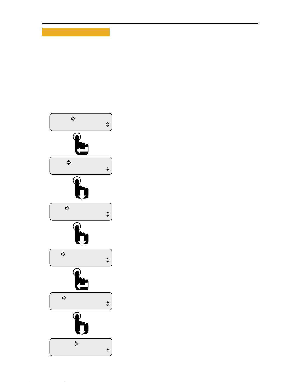
• Alarm Output
The alarm output setting controls whether the alarm output pin is turned o when an alarm condition
occurs and the Enter switch is pressed� This function is also dependant upon the Mute setting for the
audible output�
If Mute is set to Temporary and Alarm Output is set to Audible, the internal and external audible devices
will temporarily turn o� If Mute is set to Permanent and the Alarm Output is set to Audible, the internal
and external audible devices will remain o until a new alarm condition occurs�
If Alarm Output is set to light, the output pin remains on regardless of the current mute setting when
the Enter switch is pressed�
Figure 1-32: Setting Alarm Output Pin Status
Exit
Return
Output-Light
Return
Output-Audio
Alarm Output
Trip-Hours
Units
Backlight
Informaon
Setup
Scroll down to the Exit option and press the Enter switch or
wait 30 seconds for last displayed CAN parameter to appear.
Pressing the Enter switch toggled the Alarm Output setting to
the light option.
The Output-Light option does not disable output pin 3 when the
Enter switch is pressed to mute an alarm notication.
When the selection arrow cursor is placed next to the
Alarm Output option, the name changes to the current alarm
output mode, i.e., Output-Audio or Output-Light.
The Audio option disables output pin 3 when the Enter switch
is pressed to mute an alarm notication.
Pressing the Enter switch toggles between the two settings.
The setting is automatically saved once changed.
Screen shows Alarm Output function prior to placing the
selection arrow cursor next to the function.
Continue to press the Down switch to place the selection
arrow cursor next to the Alarm Output function.
The Setup Menu appears with the selection arrow cursor
next to the Backlight option.
Scroll down to place the selection arrow cursor next to the
Alarm Output option.
From the Main Menu, scroll to place the selection arrow cursor
next to the Setup option.
Press the Enter switch to view the Setup Menu functions.
Page 39
33
NexSysLink® 2" Stand-Alone CAN Display Operation Manual SAE J1939
© 2011 Beede Electrical Instrument Co., Inc.
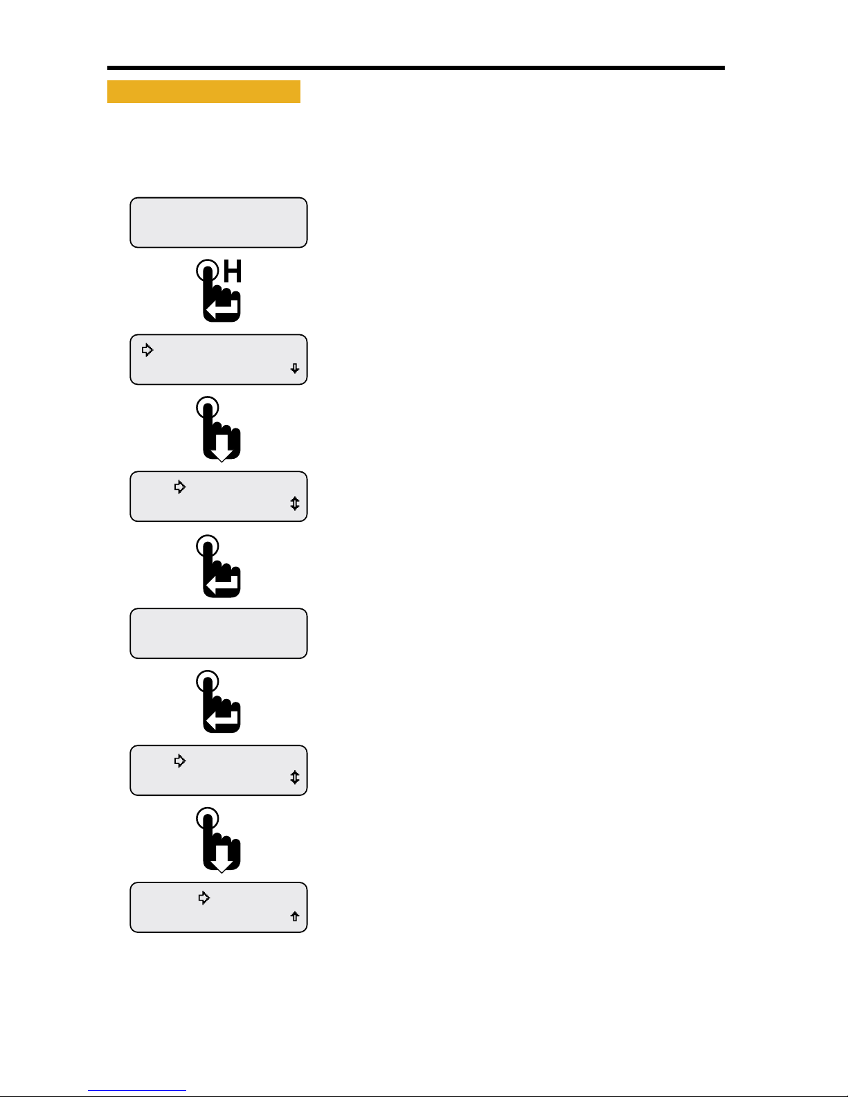
• Firmware Information
Firmware part number, revision and release date are available when selecting the Information option
from the Main Menu�
Figure 1-33: Viewing Firmware Revision
Exit
Exit
Information
861449B 4.28.11
Information
Exit
Information
Faults Active
Maintenance Hours
Engine Hours
1049.3
Scroll down to the Exit option and press the Enter switch or
wait 30 seconds for the last displayed CAN parameter to appear.
Pressing the Enter switch returns the Information Main Menu
option.
The information screen displays the rmware part number,
revision and release date.
Press the Enter switch to exit the information display or wait
30 seconds for the last displayed CAN parameter to appear.
Scroll down to place the selectio arrow cursor next to the
Information option of the Main Menu.
Press the Enter switch to view rmware information.
First two Main Menu options appear with the selection arrow
cursor next to the Maintenance Hours option.
Note: Instrument conguration may show vehicle trip.
With a CAN parameter displayed, press and hold the Enter switch
to open the Main Menu.
Engine Hours parameter shown as an example only.
Page 40

34
NexSysLink® 2" Stand-Alone CAN Display Operation Manual SAE J1939
© 2011 Beede Electrical Instrument Co., Inc.
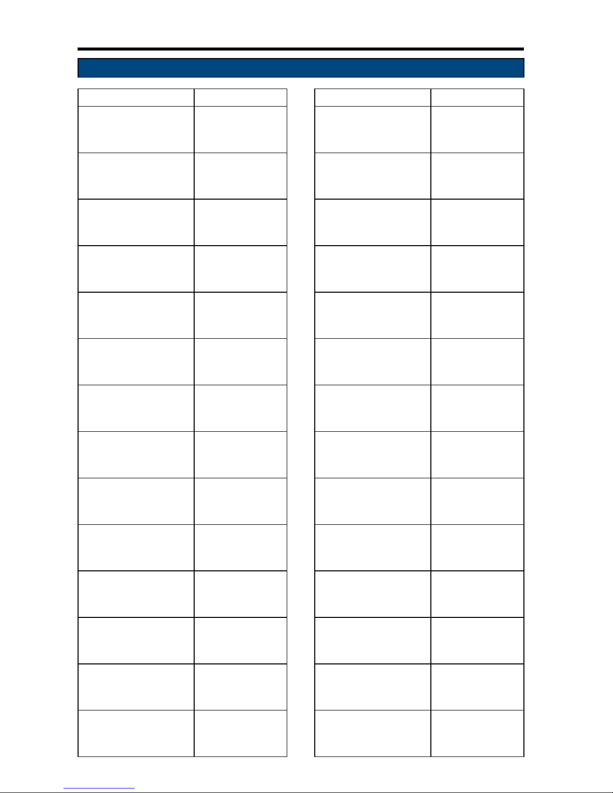
• Implementation of SAE J1939 Parameters
Parameter Name SPN PGN Range LCD Display Name
Accelerator Pedal Position 1 91 61443 0-100% Accel Pedal %
Charging System Potential 167 65271 0-50 Volts Alternator
Engine Average Fuel Economy 185 65266 0-200 MPG Avg Fuel Econ
Net Battery Current 114 65271 -125 - 125 Amps Battery Curr
Battery Potential/Power Input 1 168 65271 0-50 Volts Battery Volt
Engine Intake Manifold #1 Pressure 102 65270 0-72 PSI Boost Press
Aftertreatment 1 SCR Catalyst Tank Level 1761 65110 0-100% Cat Tank Lvl
Aftertreatment 1 SCR Catalyst Tank
Temperature
3031 65110 -40 - 400 ºF Cat Tank Temp
Engine Coolant Level 111 65263 0-100% Coolant Level
Engine Coolant Pressure 109 65263 0-72 PSI Coolant Press
Engine Coolant Temperature 110 65262 0-400 ºF Coolant Temp
Transmission Current Gear 523 61445 -6 - 30 Position Current Gear
Engine Oil Level 98 65263 0-100% Eng Oil Level
Engine Oil Pressure 100 65263 0-140 PSI Eng Oil Press
Engine Oil Temperature 1 175 65262 0-500 ºF Eng Oil Temp
Engine Total Hours of Operation 247 65253 0-999999 Hours Engine Hours
Engine Speed 190 61444 0-10,000 RPM Engine Speed
Engine Exhaust Gas Temperature 173 65270 0-3000 ºF Exh Gas Temp
Engine Instantaneous Fuel Economy 184 65266 0-200 MPG Fuel Economy
Fuel Level 1 96 65276 0-100% Fuel Level 1
Fuel Level 2 38 65276 0-100% Fuel Level 2
Engine Fuel Delivery Pressure 94 65263 0-140 PSI Fuel Pressure
Engine Fuel Rate 183 65266 0-40 GPH Fuel Rate
Engine Fuel Temperature 1 174 65262 0-400 ºF Fuel Temp
High Resolution Total Vehicle Distance 917 65217 0-999999 Miles HR Vehicle D
Hydraulic Oil Level 2602 65128 0-100 PSI Hydr Oil Lvl
Hydraulic Temperature 1638 65128 0-400 ºF Hydraulic Temp
Engine Intercooler Temperature 52 65262 0-400 ºF Intrcoolr Tmp
Engine Intake Manifold 1 Temperature 105 65270 0-400 ºF Manifold Temp
Engine Percent Load At Current Speed 92 61443 0-120% Percent Load
Power Takeo Oil Temperature 90 65264 0-400 ºF PTO Oil Temp
Power Takeo Speed 186 65264 0-8000 RPM PTO Speed
Wheel-Based Vehicle Speed 84 65265 0-200 MPH Speed
Engine Throttle Position 51 65266 0-100% Throttle
Transmission Oil Level 124 65272 0-100% Trans Oil Lvl
Transmission Oil Pressure 127 65272 0-500 PSI Trans Oil Prs
Transmission Oil Temperature 177 65272 0-500 ºF Trans Oil Tmp
Total Vehicle Distance 245 65248 0-999999 Miles Vehicle Dist
Page 41
35
NexSysLink® 2" Stand-Alone CAN Display Operation Manual SAE J1939
© 2011 Beede Electrical Instrument Co., Inc.
• Parameter Icons & Descriptions
Parameter Icon Description Parameter Icon Description
Accelerator Pedal
Position
Engine RPM/Speed
Alternator Current
or Voltage
Fuel Level
Average Fuel
Economy
Fuel Level 2
Battery Voltage
or current
Fuel Pressure
Boost Pressure
Fuel Rate/Flow
Total
Engine Coolant
Level
Fuel Temperature
Engine Coolant
Pressure
Hydraulic Oil Level
Engine Coolant
Temperature
Hydraulic Retarder
Oil Temperature
Engine Exhaust Tem-
perature
Instantaneous Fuel
Economy
Engine Intercooler
Temperature
Percent Load
Engine Manifold
Temperature
Power Takeo Oil
Pressure
Engine Oil Level
Power Takeo Oil
Temperature
Engine Oil Pressure Power Takeo Speed
Engine Oil
Temperature
Speed,
Wheel or Water
Based
Page 42
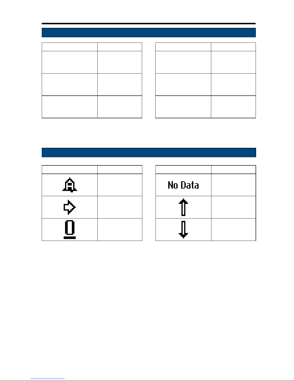
36
NexSysLink® 2" Stand-Alone CAN Display Operation Manual SAE J1939
© 2011 Beede Electrical Instrument Co., Inc.
• Parameter Icons & Descriptions
Parameter Icon Description Parameter Icon Description
Throttle Position
Transmission Gear/
Actual Gear/Current
Gear
Total Engine Hours
Transmission Oil
Pressure
Total Vehicle
Distance
Transmission Oil
Temperature
• Menu Navigation Icon Descriptions
Menu Navigation Icon Description Menu Navigation Icon Description
Alarm Indicator
(Blinks)
No CAN Data
Present
Selection Arrow
Cursor
Higher Than Alarm
Threshold Indicator
Blinking Bar Cursor
(Shown under
number 0, zero)
Lower Than Alarm
Threshold Indicator
Page 43

37
NexSysLink® 2" Stand-Alone CAN Display Operation Manual SAE J1939
© 2011 Beede Electrical Instrument Co., Inc.
• Notes
Page 44

WARRANTY
Beede Electrical Instrument Co., Inc warrants all
instruments and accessories free from all defects in
workmanship and materials on gauges that are less than
three (3) years old or have been in service fewer than
two (2) years and, at no charge, will replace or repair at
Beede’s option all instruments that fail.
Contact Beede for complete details.
Thank you for purchasing a Beede® Instrument.
Our instruments are designed and manufactured for you in the U.S.A.
Visit our web site at www.beede.com or contact customer service for
information on this or other Beede® instruments.
THANK YOU!
 Loading...