

Page 1
This document provides installation steps for racking the Unity Storage 224 Expansion, and cabling all
Nexsan storage components for power, and for connectivity to Unity.
1
Firmware Version 2.0
Quick Start Guide
NEXSAN Unity Storage 224 Expansion
Taking delivery
Check to ensure that no damage has been sustained
to the packaging in transit. If any of the Unity storage
components appear damaged, you should file a
damage claim with your reseller.
Hardware overview
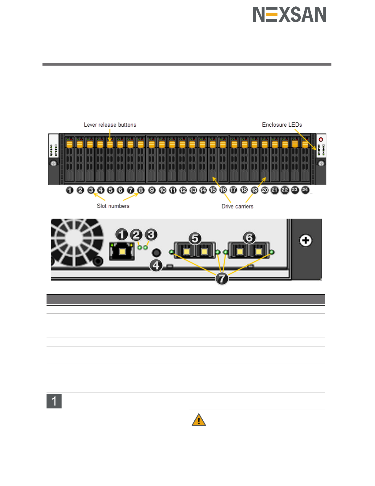
The main components of the US 224 are shown in
these diagrams.
Front view (bezel removed)
Rear view controller I/O components
Prepare for installation
A Carefully read safety notices on page 4.
B Ensure ahead of time that you have a suitable
rack; see Rack and enclosure specifications on
page 4.
C Ensure that you have a Phillips screwdriver.
D Arrange for someone to help you unpack the
system.
Item Name Description
1 LAN port Not used with Unity Storage Expansions
2 Status LED Green: Initialization successful
Red: Initialization failure
3 Unit ID status LED On/Off
4 BMC Reset button Resets the base management controller
5 SAS IN ports Serial Attached SCSI IN ports from the head unit
6 SAS OUT ports SAS OUT ports to another storage unit
7 SAS link status LEDs (2 IN, 2x OUT) Green: All four physical layers (PHY) of each port
connected with consistent link speed (12 G or 6G)
Red: Single PHY degraded link speed or
disconnected
CAUTION: Acclimate new disk drives to
room temperature for two hours before you
install them.
Page 2
2 — US 224 Quick Start Guide
Unpack the US 224
A Remove all the components from packaging.
Support the chassis from underneath as you pull
it out of the foam insert.
Do NOT lift out the US 224 chassis from its
packaging using the controller handles or
attached rails.
B Place the components on an anti-static surface
until you are ready to use them.
US 224 package contents
One US 224 Expansion (with front bezel)
2 outer-rack rail assemblies (inner-chassis rails
are already installed)
4 mounting screws with 4 washers to attach
outer-rack rails to the rack (1 on the front and 1
on the back for both the left and right rail
assemblies)
2 long screws to secure the chassis to the rack
from the front (attached to the chassis)
FASTier, SSD, and HDD drives. Check that the
components included in your shipment
correspond to your packing slip.
SAS cables (HD Mini SAS to HD Mini SAS)
Two power cables
1 electrostatic discharge (ESD) wrist strap
CD containing the Discovery Wizard.
Rack the US 224
Step 1: Remove the front bezel
A Turn the key lock at the right end of the bezel to
the unlock position.
B Unhook the left end of the bezel from the chassis.
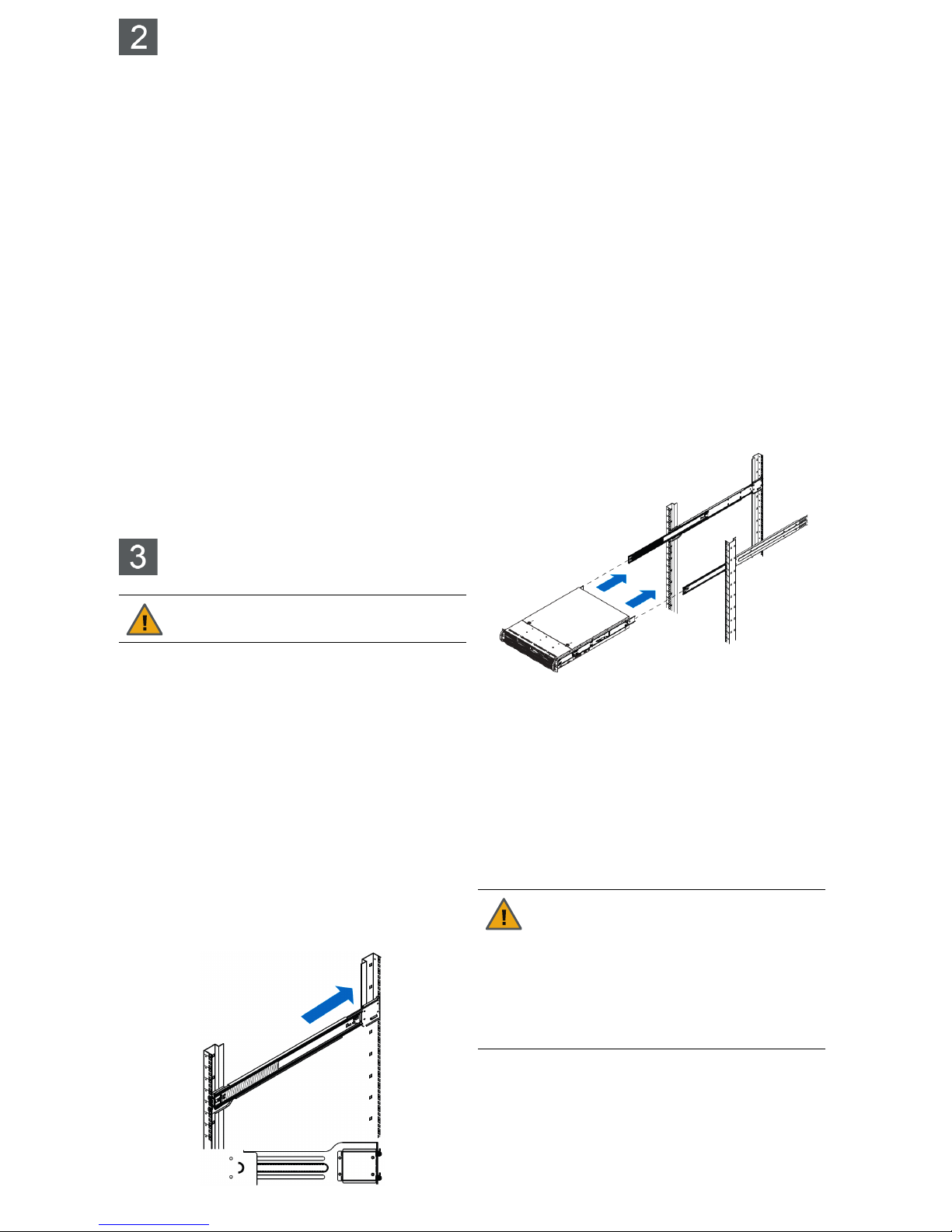
Step 2: Install the outer-rack rails on the
rack
A Attach the RIGHT and LEFT outer-rack rails to
the rack by inserting the hooks included on the
rails into the holes provided on the rack.
The hooks should be located in the MIDDLE
holes of the rack units selected.
B Extend rail assemblies to fit the depth of the rack.
Pull on the rear of the assembly until the hooks
reach the back of the rack.
C Screw the rails to the rack using the mounting
screws provided.
The screws should be secured in the BOTTOM
hole of each of the rails.
Step 3: Install the inner rails on the chassis
(if necessary)
A Extend the inner rail toward the front of the rail
assembly as far as possible, then depress the
locking tab to pull it completely out.
B Place the inner rail on the side of the chassis
aligning the hooks of the chassis with the rail
extension holes.
C Slide the extension toward the front of the
chassis.
D If desired, secure the chassis with screws.
E Repeat for the other inner rail.
Step 4: Install the US 224 on the rack
A Lift the US 224 chassis from each side—not from
the front and back.
B Line up the inner-chassis rails with the front of the
outer-rack rails.
C Slide the inner-chassis rails into the outer-rack
rails, keeping the pressure even on both sides;
you have to depress the locking tabs when
inserting.
D Push the US 224 completely into the rack; you
should hear the locking tabs click into position.
E Tighten the thumbscrews that hold the front of the
US 224 to the rack.
Step 5: Install the disk drives and FASTier
read cache SSDs
Installation order:
1 Install the FASTier Read Cache SSDs from the
LEFT, starting with the FIRST slot.
2 Install the disk drives in any order in the remaining
slots.
CAUTION: Physical installation requires
two people.
CAUTION: Put on the ESD wrist strap
before starting:
A Slip the wrist loop over your hand (left or
right), then tighten the loop against your
wrist.
B Attach the clip end of the anti-static wrist
strap to a properly grounded metal
surface.
Page 3
3 — US 224 Quick Start Guide
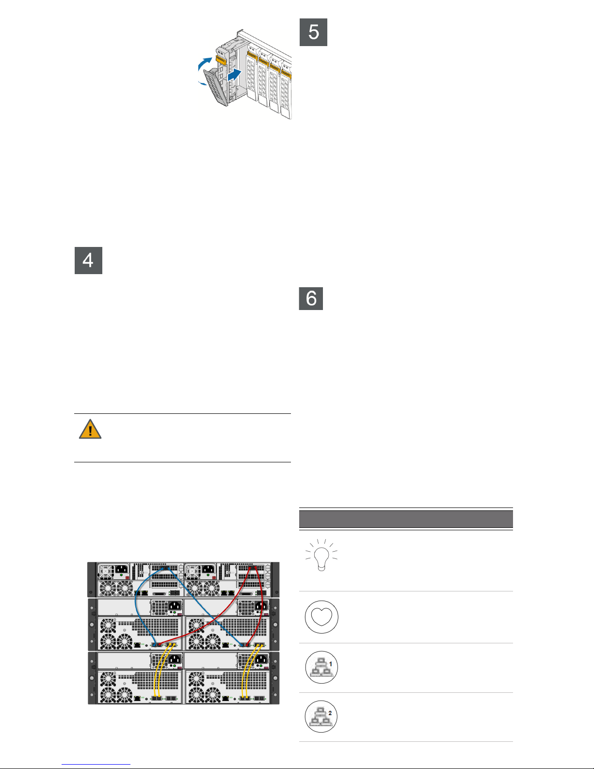
To install the drives:
A Slide the release button
on the front of the drive
carrier and open the
handle.
B Insert the hard-drive
carrier into the drive bay
until the carrier contacts
the backplane.
C Close the hard-drive
carrier handle to lock the drive in place.
D Repeat these steps for each drive.
Install the Nexsan Unity Storage System
Unpack and install any Nexsan Unity Storage
Systems (such as the Unity 4400 or Unity 6900)
included in your Unity shipment.
For detailed instructions, refer to the appropriate
Nexsan Unity Quick Start Guide included in the
packaging.
Connect the US 224
This section describes the steps for connecting the
power, and for connecting a Unity Storage System to
the US 224
.
Step 1: Connect the US 224 to the Unity
Storage System
Connect from the Add-on SAS OUT ports on each
storage system controller to the SAS IN ports on
the expansion controllers, as shown in Unity 4400
with US 224 on page 3.
Step 2: Connect the power cables
A Plug the power cords into their respective power
supplies on the rear of the US 224.
B Plug the power cords connected to the power
supply units into a high-quality strip that offers
protection from electrical noise and power surges.
Unity 4400 with US 224
NOTE:
The Unity Storage System is hot pluggable:
Once in service, powering down is not normally
required to add a Unity Storage Expansion.
Power on the US 224
Step 1: Power on the US 224
A Power on the US 224 by pressing and holding the
power button located on the right front panel of
the chassis until the power LED lights up.
B Wait approximately 1 minute for the drives to all
become ready.
C Verify that all drive carrier activity LEDs are
illuminated in green. If a drive carrier activity LED
does not light up, check to make sure the
corresponding drive is properly seated in the
chassis.
Step 2: Reattach the front bezel
If all LEDs indicate normal operational status,
reattach the front bezel to the US 224:
A Hook the left end of the bezel onto the chassis.
B Fit the right side of the bezel onto the chassis.
C Turn the key lock at the right end of the bezel to
the lock position to secure the bezel to the chassis.
Monitor the US 224
This section describes the front panel LEDs that help
you monitor the Nexsan US 224.
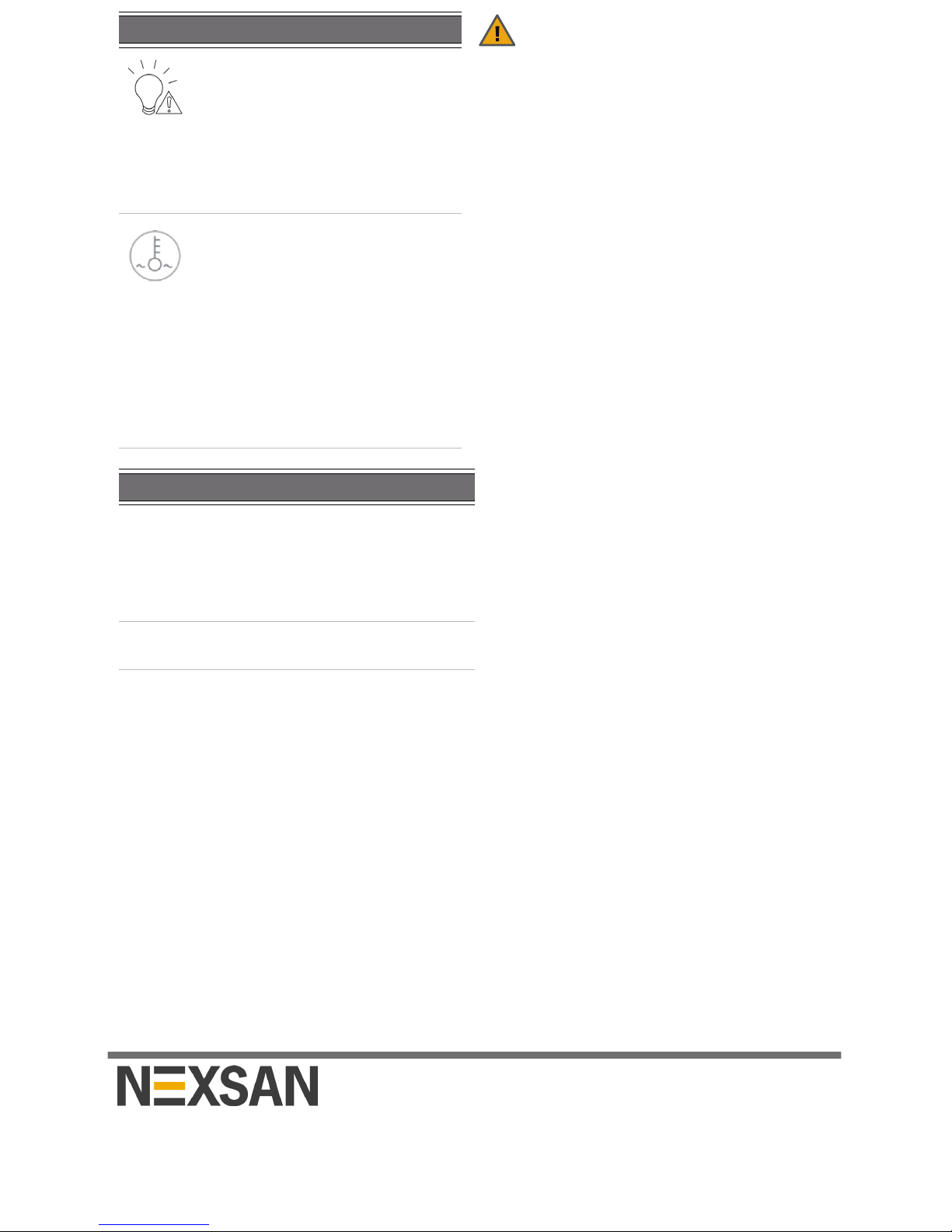
Control Panel LEDs
The two control panels located on the front left and
right sides of the US 224 have several LEDs. These
LEDs provide you with critical information related to
the corresponding node.If the Power fail or Fan fail
LED illuminates, replace the component as
described in the Nexsan Unity Storage Expansion
Reference Guide.
Drive carrier LEDs
Each drive carrier on the US 224 has two LEDs. If a
drive fails, replace the drive as described in the
Nexsan Unity Storage Expansion Reference Guide.
CAUTION: Do not connect to the Unity
Storage Expansion from the on-board SAS
ports on either the Unity 4400 or the Unity
6900.
LED Indication
Power
Indicates power is being supplied to
the system’s power supply units. This
LED is illuminated when the system is
operating.
Heartbeat
This is a server board heartbeat LED
and indicates that power is being
supplied to the server board.
NIC1
Indicates network activity on the LAN1
port when flashing.
NIC2
Indicates network activity on the LAN2
port when flashing.
Page 4
Copyright © 2010-2017 Nexsan Corporation. All Rights Reserved. Nexsan®, Unity™, Unity 2200™, Unity 4400™, Unity 6900™, Unity 2200X™, US 224™,
US 316™, US 424™, US 460, ™ FASTier™, and the Nexsan logo are trademarks or registered trademarks of Nexsan Corporation. All other trademarks
and registered trademarks are the property of their respective owners.
Nexsan 900 E Hamilton Ave, Suite 230, Campbell, CA 95008 | p. 1.866.463.9726 | www.nexsan.com
Part number: P0450172 Rev: B Release Date: June 2017
Related Documentation: Nexsan Unity Hardware Maintenance Guide,
Nexsan Unity Software User Guide, Nexsan Unity nxadmin CLI Reference
Guide
Technical Support
By Phone:
U.S. & Canada: +1 (866) 263-9726
Global: U.S. Toll +1 (760) 690-1111
By Email: [email protected]
By Web: http://helper.nexsansupport.com/unt_support.html
Safety notices
This equipment must be installed and operated in
compliance with local laws and regulations.
Ensure that the ambient temperature at the
installation is between 5°C (41°F) and 30°C
(86°F). If the temperature at the site is not actively
regulated, ensure that daily and seasonal
temperature changes will not result in the ambient
temperature going outside these limits.
Always fully stabilize racks with wall anchors or
stabilizing legs, or both, before mounting the
Nexsan storage unit or any other components on
the rack.
Situate the rack so that full air flow at both the
front and the rear of the Nexsan storage unit is
possible.
Ensure that the floor beneath the mounting rack
has enough load-bearing capacity to support the
rack and all mounted components.
Always fully secure all rack-mounting hardware
when installing the Nexsan storage unit in a rack.
Insufficient rack-mount support may allow the unit
to fall onto other rack-mounted hardware or onto
the floor, potentially damaging equipment or
causing injury to nearby personnel.
Rack and enclosure specifications
Rail kit mounting
2U enclosure height
The rack must have square roles
Maximum distances: 30" (800 mm)
Enclosure dimensions
Height: 3.5’’ 88 mm
Width: 17.2’’ 437 mm
Depth: 25.5’’ 641 mm
Weight: 56 lbs 25.5 kg (no drives installed)
85 lbs 38.6 kg (all drives installed)
Power requirements
Power supply: 1,200W
Input voltage: 100-240V
Amperage: 12V (100A @ 240V), +5Vsb (6A @
240V, 4A @ 100V)
Power consumption: varies depending on the
number and size of drives, running fans, and room
temperature
Power fail
Indicates a power supply module has
failed. The second power supply
module takes the load and keeps the
system running, but the failed module
should be replaced as soon as
possible.
This LED should be off when the
system is operating normally.
Fan fail
When flashing, this LED indicates a
fan failure.
When illuminated continuously, this
LED indicates an overheat condition,
which may be caused by cables
obstructing the airflow in the system or
the ambient room temperature being
too high.Check the routing of the
cables and make sure all fans are
connected and operating normally. You
should also check to make sure that
the chassis covers are installed.
Drive LED Indication
Green
A steady green LED indicates the
drive is powered on.
If this LED is not lit, the drive is not
getting power.
If this LED is flashing, the drive is
being accessed (read or write).
Red
A steady red LED indicates a drive
failure.
LED Indication
 Loading...