

Page 1
This document helps you quickly get your Nexsan UNITY224X™ unpacked, mounted, and connected. For
detailed instructions, see the Nexsan UNITY Expander Unit Reference Guide.
Quick Start Guide
NEXSAN UNITY224X
TM
1
UNIFIED HYBRID STORAGE
Firmware Version: UNITY 1.0
Taking Delivery
When you receive your Nexsan UNITY224X shipment, check to ensure no damage has been sustained to
the packaging in transit. If the UNITY224X itself shows damage, you should file a damage claim with the
carrier who delivered it.
UNITY224X Hardware overview
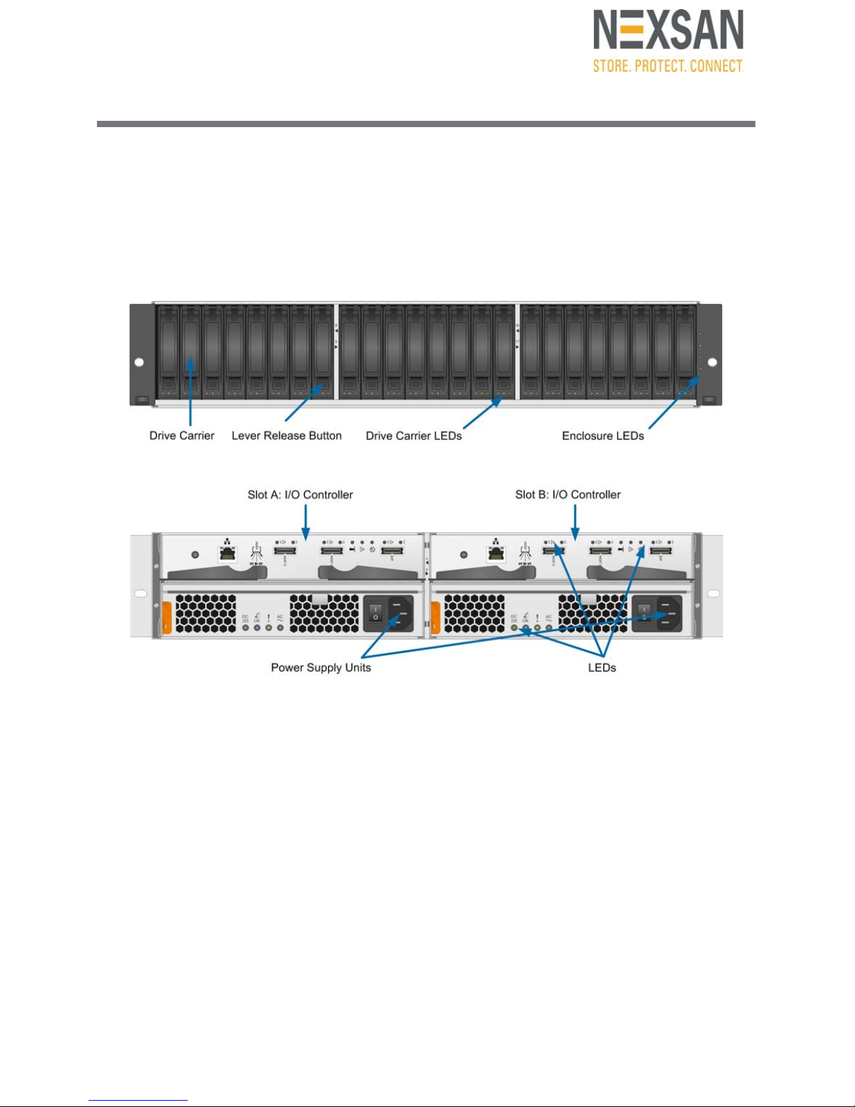
The main components of the UNITY224X Expander unit are shown in these diagrams.
Front View
Rear View
Disk drive specifications
The UNITY224X Expander unit supports up to 24
SAS and/or SDD disk drives.
Each disk drive is mounted in a drive carrier with a
push-button lever for quick installation and removal.
NOTE: A disk drive must not be removed from its
drive carrier. A disk drive removed from its carrier is
not covered by the hardware warranty.
Each drive carrier has three LEDs, which indicate
status. Disk drives are hot-swappable.
The slots are numbered from 1 to 24 (left to right).
Disk drives must be qualified by Imation and meet
these specifications:
10,000 rpm or eMLC SSD
Hot-swap/hot-plug support
SAS device plug connector
6 Gb/sec or 3 Gb/sec data rate
2.5” form factor
Upgradable disk drive firmware
Cable specifications
To connect the UNITY224X, use high-quality SAS
cables that meet these length requirements:
Minimum length: 0.5 meters
Maximum length: 3 meters
For updated disk drive information or to purchase
approved SAS cables, please contact your Imation
sales representative or reUNITY6000UNITY6000
SAS I/O controllers, which are installed on the back
of the enclosure.
Each controller has three SAS ports:
Use the input ports (Host 1/2) to connect to the
Nexsan UNITY appliance.
Use the expansion port to connect to another
UNITY224X Expander unit; see Connection and
configuration options on page 1 for more
information.
Page 2
2
Power Supply Units (PSUs)
The UNITY224X Expander unit has two PSUs
located on the back of the unit.
The cooling fans in each PSU run on separate
circuits from the power supply . Therefore, if one PSU
fails, its fans continue to run on power supplied by
the other PSU.
Each PSU has four LEDs, which indicate status.
PSUs are hot-swappable.
Maintaining correct airflow and cooling
In addition to supplying power, the PSUs maintain
proper airflow and cooling within the enclosure.
Because there are two PSUs, the UNITY224X can
continue to operate even if one PSU fails.
However, for proper operation and cooling, two
PSUs with fully-functional fans must be installed at
all times. The UNITY224X can run temporarily with
a single PSU while you install a new one—you must
install a second PSU as quickly as possible to
maintain correct airflow and cooling.
Prepare for the Installation
A Carefully read safety notices on page 6.
B
Ensure ahead of time that you have a suitable
rack; see
Rack and Enclosure Specifications
on page 6
.
C Ensure that you have a Phillips screwdriver.
D Have someone assist you during installation.
Unpack the UNITY224X
A Remove all the components from packaging.
Position hands under the chassis to pull it free
from the foam insert.
Do NOT lift out the UNITY224X chassis from its
packaging using the controller handles or
attached rails.
B Place the components on an anti-static surface
until you are ready to use them.
Package Contents
Your shipment includes these components:
UNITY224X Expander Unit (I/O modules)
Rack-mounting hardware:
6 M5 x 10 mm Phillips flat-head screws to
attach outer-rack rails to the rack (in bag #1)
2 M5 x 13 mm Phillips pan-head screws to
secure chassis from the front (in bag #2)
Two power cords
Two SAS cables
24 drives: If you ordered data SSDs, the carriers
will have 6, 12, or 18 free drive slots, depending
on the number of SSDs.
Rack the UNITY224X
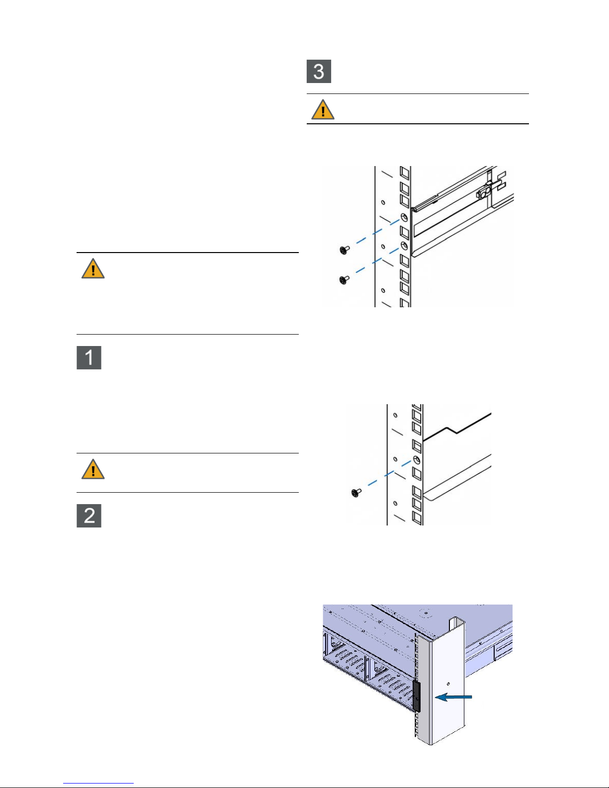
Step 1: Install the rail assemblies
A Loosen the screws before you secure the rails to
the supports of the rack.
B Secure both REAR mount ears to the vertical
supports using two of the M3x8mnm screws on
each side:
One screw in the last hole of the rack space
One screw in the middle hole of the rack space
C Secure both FRONT mount ears to the vertical
support on the middle hole of the rack space,
using one M3x8mm screw on each side.
D Ensure that the rails are level on both sides and
that both rails are installed at the same height.
E Slide the unit onto the rails, then push it all the
way back until the rack mount ears are flush
against the vertical supports and the unit rests
completely on the rails.
CAUTION: Once you remove a failed
PSU, you must replace it within five
minutes or the UNITY224X may overheat
and shut down to prevent hardware
damage. This shutdown is immediate—
unexpected loss of data access and
permanent data loss may occur.
CAUTION: Acclimate new disk drives to
room temperature for 2 hours before
installation.
CAUTION: Physical installation requires
two people.
Page 3
3
Step 2: Install the disk drives on the
expansion unit
Installation order:
1 Install the F AST ier Write Cache SSD in the FIRST
slot on the LEFT.
2 Install the FASTier Read Cache SSD in the
SECOND slot on the LEFT.
3 Install the disk drives in any order in the
remaining slots.
To install the drives:
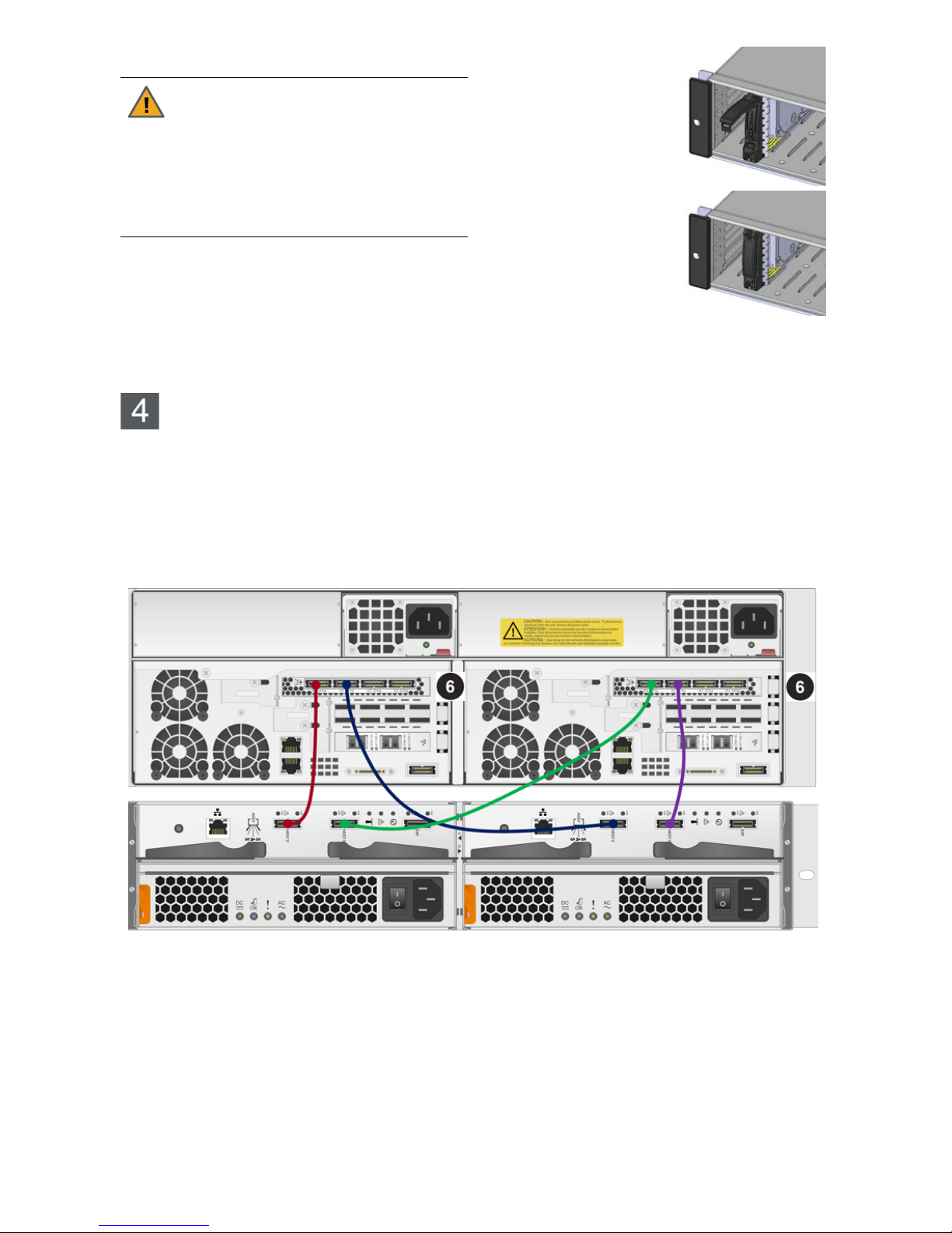
A Hold the disk drive so
that the LEDs are on the
bottom and THE LEVER
IS FULLY OPEN.
B Slide the disk drive into
the drive slot using the
lever until the drive locks
into place.
C Gently push the lever
until it mates with the
latch on the bottom of the
drive slot and clicks into
place.
D Repeat for all remaining
disk drives.
Connect the UNITY224X
This section explains how to connect a single UNITY224X Expander unit to the Nexsan NST5300 or the
Nexsan UNITY6530.
Step 1: Connect a single UNITY224X Expander unit
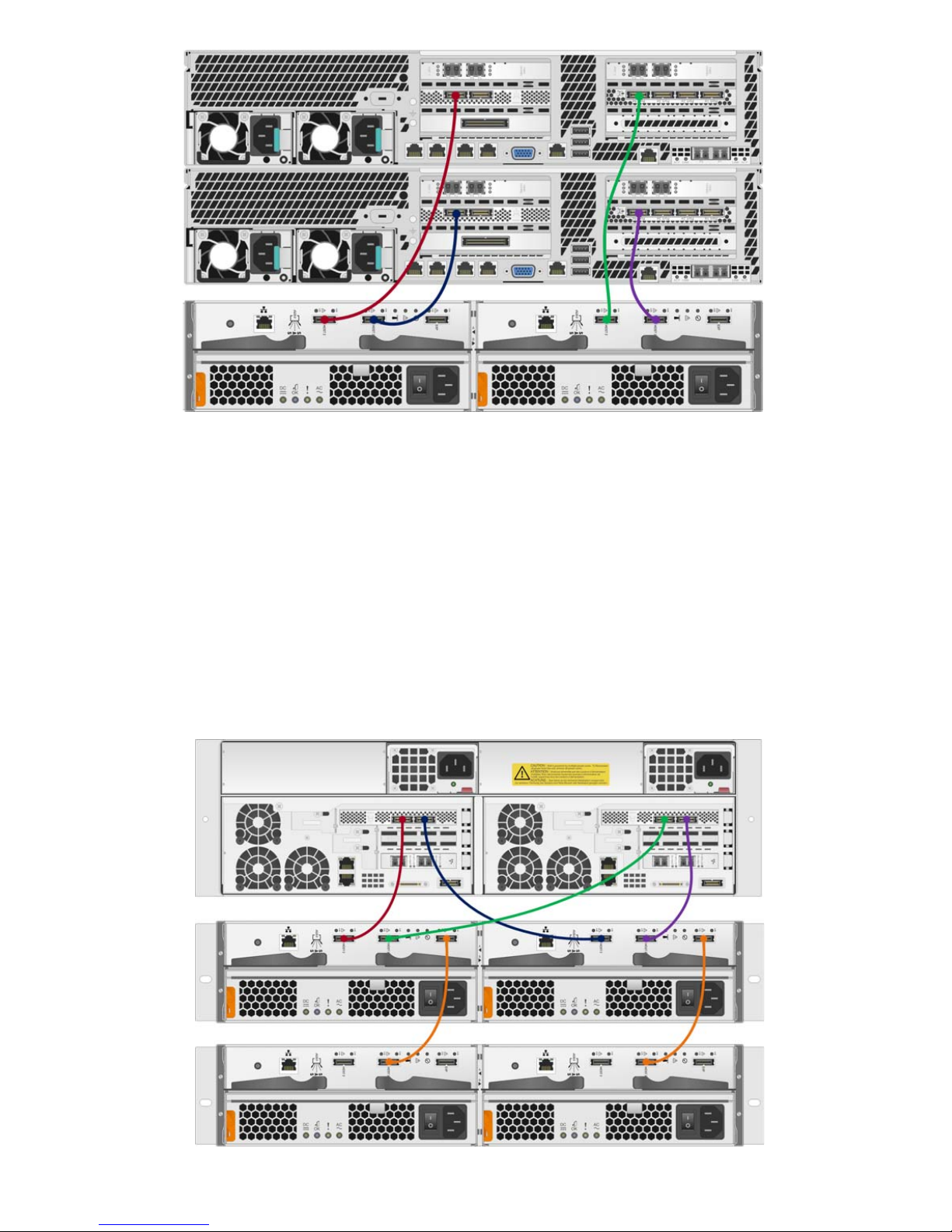
Use the external SAS cables to connect from the SAS HBA ports on each UNITY appliance to the
input ports on each UNITY224X controller.
Basic configuration with the NST5000
CAUTION: Put on the ESD wrist strap
before starting:
A Slip the wrist loop over your hand (left or
right), then tighten the loop against your
wrist.
B Attach the clip end of the anti-static wrist
strap to a properly grounded metal
surface.
Page 4
4
Basic configuration with the UNITY6000
Step 2: (Optional) Connect Additional UNITY224X Expander Units
You can connect up to 3 UNITY224X Expander units together to create a daisy chained set, and then
connect this daisy chained set to the Nexsan NST5300 or Nexsan UNITY6530.
This configuration requires both the 2x- and 4x-port PCIe to Serial Attached SCSI (SAS) host bus adapters
on the UNITY appliance (available as optional components on the NST5000).
Please contact your Imation sales representative or reseller for information about daisy-chaining
UNITY224X Expander units, and purchasing optional PCIe to Serial Attached SCSI (SAS) host bus
adapters for the Nexsan NST5300.
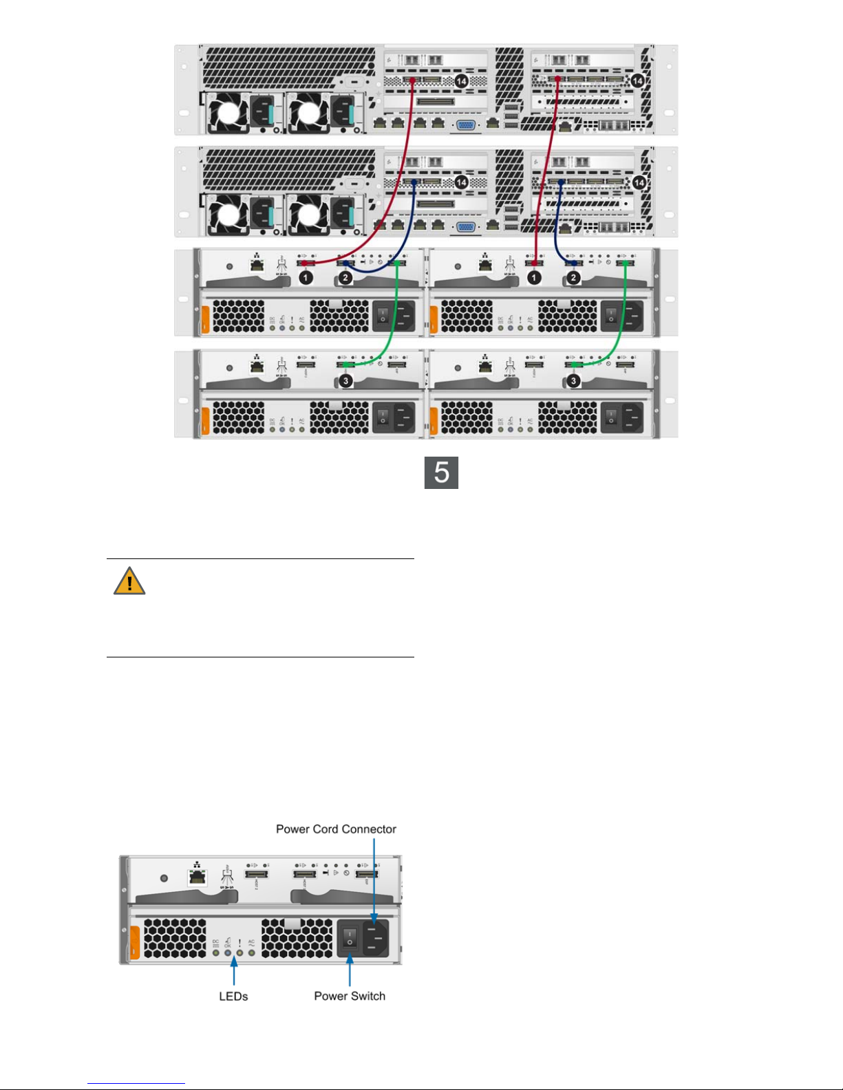
A Use the external SAS cables to connect the expansion port to the input port on the next UNITY224X
Expander unit.
When daisy chaining UNITY224X Expander units, ensure that only controllers in Slot A are daisy
chained together, and that only controllers in Slot B are daisy chained together.
B To expand your configuration with multiple UNITY224X expander units, continue to connect the
expansion ports of the previous expander unit to the input port of the next expander unit.
NST5300 connected to the UNITY224X in a daisy chain
Page 5
5
UNITY6530 connected to the UNITY224X in a daisy chain
To see diagrams showing an NST5000 or
UNITY6000 connected to additional UNITY224X
units in a daisy chain, refer to the Nexsan UNITY
Expander Unit Reference Guide.
Step 3: Connect the power cables
A Plug the power cords into their respective power
supplies on the rear of the UNITY224X
enclosure(s).
B Using the included power cords, connect each
power supply unit to an AC power source.
We strongly recommend that you use an
uninterruptible power supply (UPS) to protect
your enclosure.
View of a single controller
Power on the UNITY224X
Expander unit(s)
Power up the UNITY224X Expander unit(s) and the
Nexsan NST5300 or the Nexsan UNITY6530 in this
sequence.
In a single UNITY224X Expander unit
configuration:
A Turn on both PSUs (power supply units) using the
power switches on the back of the enclosure.
B Wait approximately 1 minute for the drives to all
become ready.
C Power on the UNITY appliance.
In an expanded, or daisy chained,
configuration:
A Power up the last enclosure in the chain up first.
B Power up the UNITY224X enclosures by pressing
the power switches on the rear of the enclosures
located on the PSU units.
NOTE: The primary (or first) UNITY224X
enclosure must be turned on LAST. (The primary
UNITY224X is the one connected directly to the
UNITY appliance). The power up order is critical
for each of the expansion boxes to properly be
seen by the previous UNITY224X in the chain.
C Wait approximately 1 minute for the drives to all
become ready.
D Power on the UNITY appliance.
CAUTION: Use only the power cords
supplied with the UNITY224X. Do not use
another type of cord or extension cords. If
you require additional power cords, please
contact your Imation sales representative
or reseller.
Page 6
Copyright © 2010-2016 Nexsan Corporation. All Rights Reserved. Nexsan®, E-Centre™, UNITY4000™, UNITY6000™, UNITY6000MC™, UNITY224X™,
E18™, E48™, E60™, FASTier™, and the Nexsan logo are trademarks or registered trademarks of Nexsan Corporation. All other trademarks and
registered trademarks are the property of their respective owners.
Nexsan 900 E Hamilton Ave, Suite 230, Campbell, CA 95008 | p. 1.866.463.9726 | www.nexsan.com
Part number: P0450158 Rev: A Release Date: June 2016
Related Documentation: Nexsan UNITY Hardware Reference Guide,
Nexsan UNITY Software User Guide, Nexsan UNITY nxadmin CLI
Reference Guide
Technical Support
By Phone:
U.S. & Canada: +1 (866) 263-9726
Global: U.S. Toll +1 (760) 690-1111
By Email: [email protected]
By Web: http://helper.nexsansupport.com/nexsan_aaq.html
Attach the front bezel
If all LEDs indicate normal operational status, attach
the front bezel to the UNITY224X:
A Unpack the front bezel of the expansion unit from
its packaging.
B Hook the left end of the bezel onto the chassis.
C Fit the right side of the bezel onto the chassis.
D Turn the key lock at the right end of the bezel to
the lock position to secure the bezel to the chassis.
Monitor the UNITY224X
To monitor the enclosure:
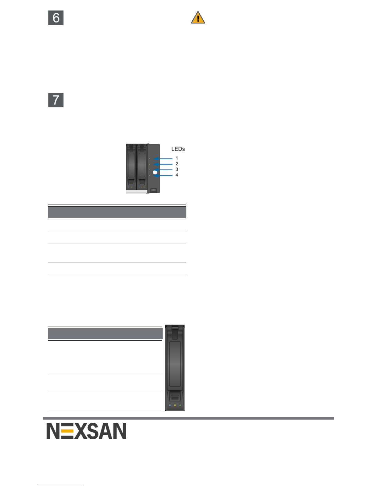
Four LEDs on the right side of the front of the
UNITY224X Expander’s enclosure indicate the
status of the whole enclosure.
When a failure occurs on a
controller or PSU unit, the
enclosure LEDs indicate an
enclosure fault.
For instructions to replace a
controller or a PSU unit,
see the Nexsan UNITY
Expander Unit Reference
Guide.
To monitor the disk drives:
Each disk drive carrier has three LEDs that indicate
the status of the disk drive. For instructions to
replace a disk drive, see the Nexsan UNITY
Expander Unit Reference Guide.
Safety Notices
This equipment must be installed and operated in
compliance with local laws and regulations.
Ensure that the ambient temperature at the
installation is between 5°C (41°F) and 30°C
(86°F). If the temperature at the site is not actively
regulated, ensure that daily and seasonal
temperature changes will not result in the ambient
temperature going outside these limits.
Always fully stabilize racks with wall anchors or
stabilizing legs, or both, before mounting the
Nexsan storage unit or any other components on
the rack.
Situate the rack so that full air flow at both the
front and the rear of the Nexsan storage unit is
possible.
Ensure that the floor beneath the mounting rack
has enough load-bearing capacity to support the
rack and all mounted components.
Always fully secure all rack-mounting hardware
when installing the Nexsan storage unit in a rack.
Insufficient rack-mount support may allow the unit
to fall onto other rack-mounted hardware or onto
the floor, potentially damaging equipment or
causing injury to nearby personnel.
Rack and Enclosure Specifications
Rail Kit Mounting
2U enclosure height
The rack has square roles
Maximum distances: 30" (800 mm)
Enclosure Dimensions
Height: 3.5’’ 88 mm
Width: 17.6’’ 447 mm
Depth: 19.3’’ 490 mm
Weight
Weight: 53 lbs 27 kg (all drives installed)
Power Requirements
Power supply: 920W
Input voltage: 100-240V
Amperage: 5V @ 45A, 3.3V @ 24A, -12V @0.6A
Input frequency: 50/60 Hz
Power consumption: varies depending on the
number and size of drives, running fans, and
room temperature
LED Condition Color Indication
1 N/A White Not used
2 On Amber Enclosure fault
3 Flash Amber Service action
allowed
4 On Green Power on
LED Condition Color Indication
Blue On Blue Service
action
allowed
(not used)
Yellow On Amber Drive
fault
Green On/
Flashing
Green Drive
ready
 Loading...