

Page 1
1
NexPump Ai Manual
NexPump, Inc.
Phone: 630-365-4639
Fax: 630-365-6919
Email: [email protected]
Web Address: www.nexpump.com
User’s Manual 7.00.0000
NexPump is a Registered Trademark of NexPump, Inc.
Copyright © 2003-2018 NexPump, Inc., All Rights Reserved
Patent Pending
Page 2
2
NexPump User’s Manual
The NexPump Ai is the World's Most Reliable Sump Pump
Box Contents
Qty. 1 - NexPump Ai System Unit
(AN - Phone Notification Module Installed)
(ANi – Wired Internet Notification Module Installed)
(ANiw – Wireless Internet Notification Module Installed)
(ENi – Wired internet with Email Notification Only)
(ENiw – Wireless internet with Email Notification Only)
Model Ai Single
Qty. 1 - High Capacity Pump w/Adapter
Model Ai Dual
Qty. 2 - High Capacity Pumps w/Adapters
Model Ai Jet
Qty. 1 - Ultra Capacity Pump w/Adapter
Model Ai Turbo
Qty. 1 - High Capacity Pump w/Adapter
Qty. 1 - Ultra Capacity Pump w/Adapter
Model Ai Rage
Qty. 2 - Ultra Capacity Pumps w/Adapters
Qty. 1 - Gray Sensor with SS mounting clamp (Sensor 1)
Qty. 1 - White Sensor with SS mounting clamp (Sensor 2)
Qty. 1 - Owner’s Manual
Purchased Separately: (Required to operate)
1 - Deep-Cycle Marine Battery (See Battery section for
more information)
You will also need to supply for installation:
• 1-1/2" or 2” rigid PVC pipe and fittings
• PVC cement and primer
• Check Valves (if applicable)
Please take a moment and review this manual before starting
installation or powering up your NexPump Ai System
TABLE OF CONTENTS
Safety Instructions ....... 3
NexPump Precautions ....... 4
Installation Procedures ....... 5
Control Box Overview ....... 7
Navigation Panel ....... 8
System Operating Status ....... 9
Mode Selection ....... 9
Pump Operations ....... 9
Sensor Operations ....... 10
AC Power ....... 10
Testing ....... 11
Battery ....... 11
Charger ....... 13
Internal Cooling Fan ....... 14
Internal Electronics ....... 14
Alerts ....... 15
Clearing/Disabling/Silencing Alarms.. 16
Configuration Menu ....... 17
Information Menu ....... 18
Advanced Menu ....... 19
Reset Menu ....... 20
Quick Reference Guide ....... 21
NexPump Specifications ....... 22
Warranty Information ....... 23
Installation Examples ....... 24
Page 3

3
Safety Instructions
Save these instructions - This manual contains important safety and operating instructions for the NexPump. Follow these
important safety precautions. Failure to follow safety precautions can result in personal injury or damage to the NexPump.
CAUTION - To reduce the risk of injury, charge only lead type rechargeable batteries. Other types of batteries may burst causing
personal injury and damage.
Do not expose the NexPump system unit to rain or snow.
Do not install the NexPump system unit where temperatures will be below freezing (32 degrees Fahrenheit).
Do not charge a battery that may be frozen. Allow the battery to sit at room temperature before connecting to the NexPump.
If an extension cord must be used, make sure
A. That the pins on the plug or extension cord are the same number, size and shape as those of the plug on the NexPump
system unit.
B. That the extension cord is properly wired and in good electrical condition.
C. That the wire size is large enough for the AC ampere rating of the NexPump system unit.
Do not operate the NexPump system unit if it has received a sharp blow, been dropped, or otherwise damaged in anyway- take it
to a qualified serviceman.
Do not operate the NexPump system unit with a damaged cord or plug - have them replaced or repaired immediately.
Do not disassemble the NexPump system unit- take it to a qualified serviceman when service or repair is required. Dis-assembly
may result in a risk of electric shock or fire and void the warranty.
Never pull directly on any wiring connected to pumps, battery, AC power or sensors. Disconnect by pulling on connectors only.
Never force the connectors out of place, they should disconnect and connect easily. Some connectors have safety latches, so make
sure they are depressed.
Never attempt any maintenance and/or cleaning with the NexPump powered up. Risk of electric shock may result.
WARNING - RISK OF EXPLOSIVE GASES WORKING IN THE VICINITY OF A LEAD-ACID BATTERY CAN BE
DANGEROUS. BATTERIES GENERATE EXPLOSIVE GASES DURING NORMAL BATTERY OPERATION.
FOR THIS REASON, IT IS OF THE UTMOST IMPORTANCE THAT EACH TIME BEFORE USING YOUR NEXPUMP
CONTROL UNIT YOU READ THIS MANUAL AND FOLLOW THE INSTRUCTIONS EXACTLY.
A SPARK NEAR THE BATTERY MAY CAUSE AN EXPLOSION.
Be sure the area around the battery is well ventilated.
Personal Precautions
If LEAD-ACID battery is used
Someone should be within range of your voice and/or close enough to come to your aid when you work near a lead-acid battery.
Have plenty of fresh water and soap nearby in case battery acid contacts skin, clothing or eyes.
Wear complete eye protection and clothing protection. Avoid touching your eyes while working near the battery.
If the battery acid contacts skin and/or clothing, wash immediately with soap and water. If acid enters the eye, immediately flood
eye with running cold water for at least ten minutes and get medical attention immediately.
When the battery fluid level is low, add distilled water in each cell until the level reaches the indicator on each cell. Do not
overfill.
Precautions for all Batteries
Page 4
4
NEVER smoke or allow a spark or flame in the vicinity of the battery.
Be extra cautious to reduce the risk of dropping a metal tool onto the battery. It might spark or short-circuit the battery or another
electrical part that may cause an explosion.
Remove personal metal items such as rings, bracelets, necklaces and/or watches when working with a battery. A battery can
produce a short circuit current high enough to weld a ring (or the like) to metal, causing a severe burn.
When cleaning the battery terminals be careful to keep corrosion from coming in contact with eyes.
Do not use the system unit for charging dry-cell batteries that are most commonly used with household appliances. These batteries
may burst and cause injury to persons and damage to property.
NexPump Precautions
NexPump system unit location
Locate the NexPump system unit as far away from the battery as the DC cables permit.
Do not operate the NexPump system unit in an area with restricted ventilation.
Do not set a battery on top of the NexPump system unit.
Do not allow the NexPump system unit to sit on top of the battery.
Do not block the NexPump system unit ventilation in any way. Allow at least six inches of free space from the fan exhaust on the
right side of the NexPump unit.
Do not install the NexPump system unit where temperatures will be below freezing (32 degrees Fahrenheit).
Do not install the NexPump system unit where it will be exposed to outside elements.
DC Connection Precautions
The NexPump unit requires a connected marine type deep-cycle battery for proper operation. You must assure the battery is
connected while the NexPump unit is operating.
When attaching the battery cables to the battery posts, secure them to insure a good connection.
The BLACK wire from the NexPump system unit connects to the NEGATIVE (-) post of the battery. The RED wire from the
NexPump system unit connects to the POSITIVE (+) post of the battery.
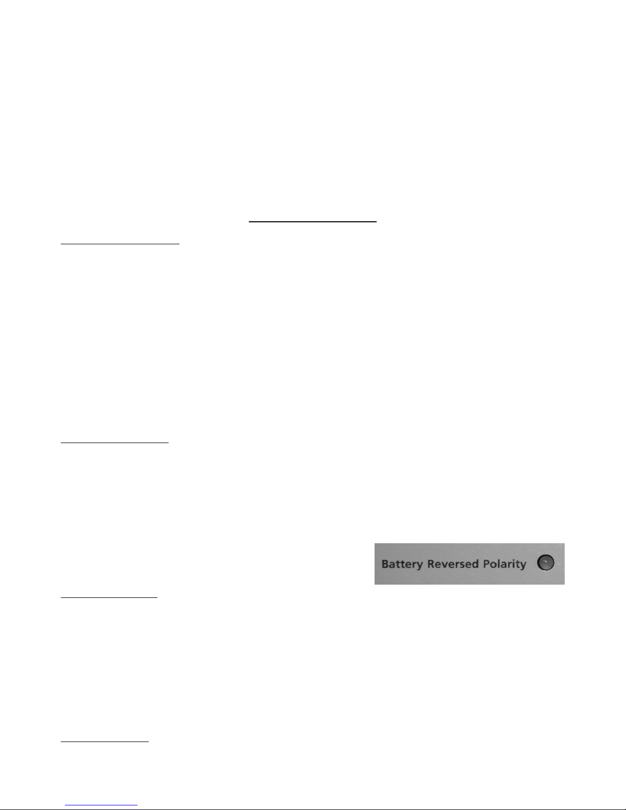
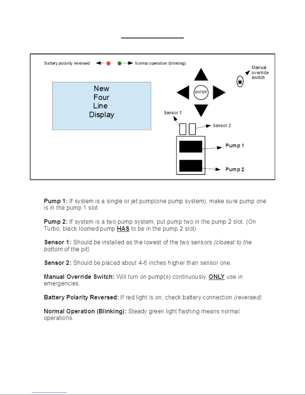
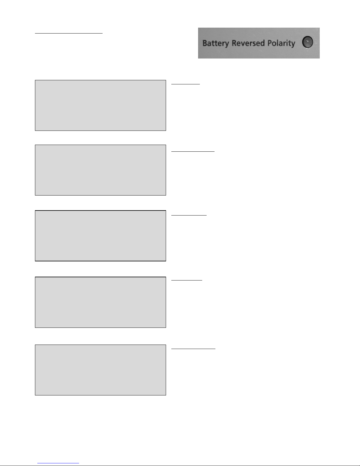
The ‘REVERSE POLARITY LED’ will illuminate if the battery connections
are reversed.
AC Power Requirements
The NexPump system unit must be operated from 120 volt household current from the AC outlet.
GROUNDING AND AC CORD INSTRUCTIONS
The NexPump system unit should be plugged into an outlet that is properly installed and grounded in accordance with all local
codes and ordinances.
DANGER- Never alter the AC cord or plug provided – if it will not fit the outlet, have a proper outlet installed by a qualified
electrician. Improper connection can result in a risk of an electric shock. An adapter should not be used with the NexPump system
unit.
Important Safe Guards
Page 5

5
Never allow other items that discharge into the sump pit to be unsecured. Unsecured items such as garden hoses, laundry hoses
and other medium used to discharge water may interfere with the NexPump pumps or sensors. Be sure to secure all items that may
be used to discharge water into the sump pit and verify that secured items will not interfere will any NexPump operations.
Installation Procedures
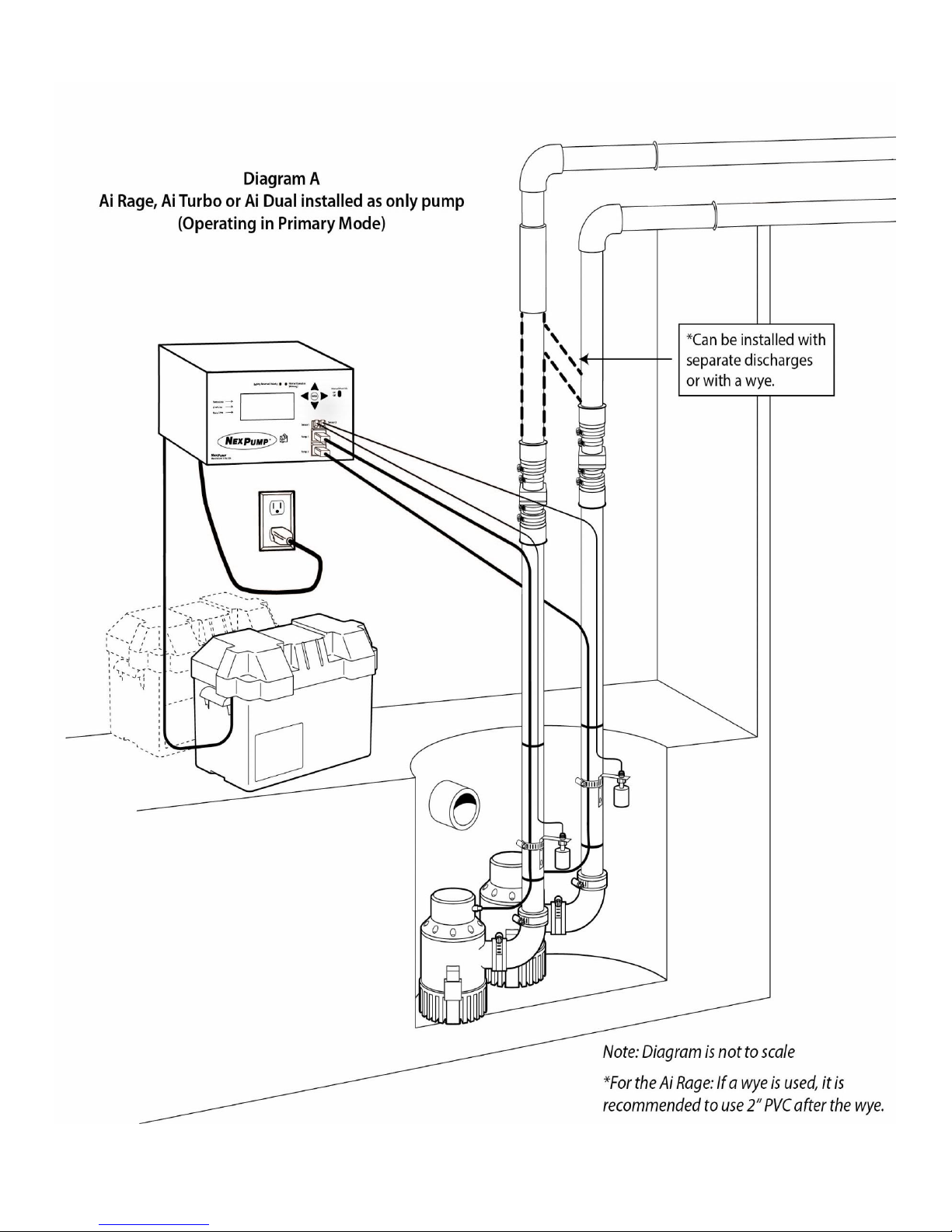
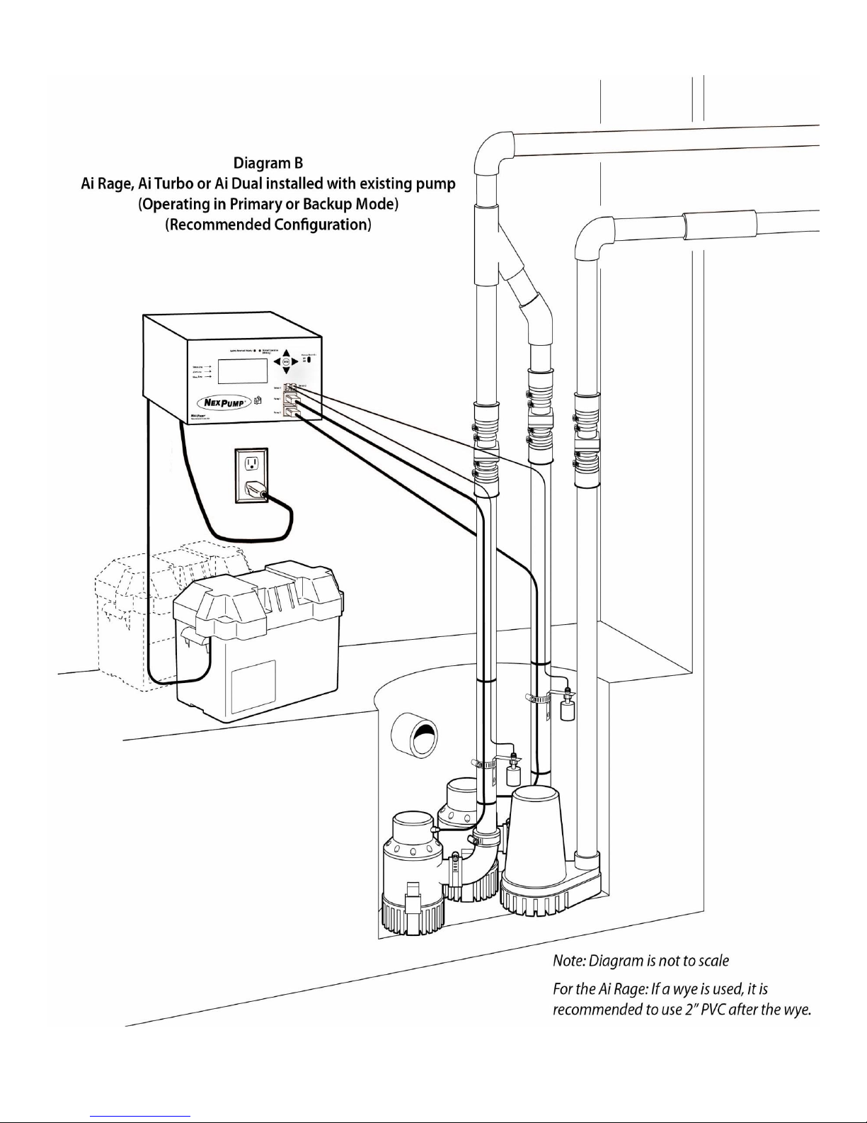
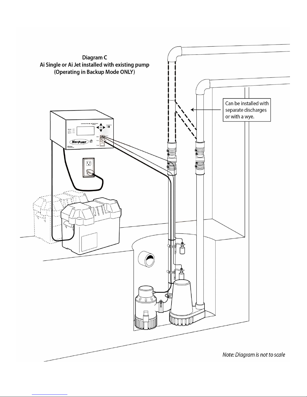
Installing the NexPump does require some plumbing expertise. You can use the installation diagrams at the end of this document
as a reference for proper installation. For a Dual Pump NexPump System, separate discharges are recommended for maximum
discharge rates and multiple output paths. If a Dual Pump NexPump System is installed as a backup, then you can use a WYE,
however install one NexPump Pump on the straight through of the WYE and your normal electric pump on the 45 degree of the
WYE. The remaining NexPump Pump should be installed as a separate discharge. You can install all the pumps in a multiple wye
configuration, however this type of installation may reduce the total discharge capacity about fifteen (15%) percent at high
discharge rates.
Points for Proper Installation
Tighten hose clamps on check valves if applicable.
Tighten pump adapters securely.
Install separate discharges for maximum discharge rate.
Make sure the RED filter screen is securely attached to each pump.
For very narrow sump pits, pumps can be stacked on top of each other. Pump 1 must be the lowest pump.
IMPORTANT: When using a check valve, a small 1/8” hole must be drilled in the vertical discharge pipe of each pump. DO
NOT DRILL INTO THE PUMP OR THE ELBOW. The hole should be drilled at a 45 degree downward angle to prevent water
spraying upwards and position the hole about 2” above the top of the elbow.
IMPORTANT: Ai Turbo NexPump. Pump 1 must be the pump with the RED WIRE LOOM.
REVIEW ALL SAFETY PRECAUTIONS AND INSTRUCTIONS BEFORE PROCEEDING!
Finishing Installation
Step 1: Positioning the Sensors
Sensor 1 is the main sensor and will operate the pump(s) when the water rises above the sensor. The gray sensor should be used
for Sensor 1. Sensor 2 does not operate exactly like Sensor 1 however, functions as a backup and high water alarm. (See Sensor
Operations). The white sensor should be used for Sensor 2. Attach the sensors to any discharge pipe securely with the supplied
stainless steel clamps (float side down, sensor cable up, mounting bracket up, remove any shipping tape). Float on each sensor
should move freely up and down.
Position the sensors as described below.
Sensor 1 (Left Sensor Receptacle)
NexPump in Backup Mode:
Position Sensor 1 approximately 4 - 6 inches above the activation level of the main pump. If not, the NexPump may show the
pumps have been activated prematurely.
NexPump in Primary Mode (only sump pump):
Position Sensor 1 approximately 2 - 4 inches above the pumps.
NexPump in Primary Mode (with electric sump pump):
Position Sensor 1 above the level of the NexPump pumps and below the level that the AC pump will turn on.
Sensor 2 (Right Sensor Receptacle)
Sensor 2 is used as a backup and alert for high water. When activated the NexPump will begin operation in a special emergency
mode and with the ‘Auto Notification’ feature will alert immediately. Position Sensor 2 about six inches above all other trigger
Page 6
6
points.
Be sure the sensor is positioned vertically with the mounting bracket at the top. Verify the sensor is not tilted in any way.
IMPORTANT: If a vent hole is drilled in the discharge pipe make sure a sensor or sensor clamp does not block the vent hole.
Do not position the sensor on the side of the discharge pipe facing the drain tile or any incoming rush of water.
Step 2: Secure Wires
Secure the pump and sensor wires to discharge pipes with nylon wire ties.
IMPORTANT: Make sure the wire ties or wires do not interfere with the operation of the sensor.
Step 3: Position Battery and System Unit
Place the battery in a battery box (if used) on the floor or on a secure shelf, rack or ledge. Position the NexPump system unit in a
secure place ideally above the floor. The pump wires and sensor wires should be long enough to position the NexPump system
unit approximately 3-4 feet above the floor. Be sure the power cord will reach the AC power socket. Secure the electrical power
cord as needed. Do not plug in at this time. Make sure battery cables will reach battery. Do not connect battery cables at this
time.
Step 4: Pump and Sensor Connections
Plug the pump connectors into the NexPump system unit. If both pumps are not on the bottom of the pit then Pump 1 must be the
lowest pump. Plug in the sensors. Primary sensor (Sensor 1) to left receptacle. Backup sensor (Sensor 2) to right receptacle. The
sensor connectors plug in with the security latch to the right of the NexPump System Unit. Verify the sensor connectors are
securely attached.
IMPORTANT: Ai Turbo NexPump. Pump 1 must be the pump with the RED WIRE LOOM.
To disconnect a pump connector, slightly depress the security latch on the bottom of the connector and pull out the connector.
To disconnect a sensor connector, slightly depress the security latch on the right side of the connector and pull out the connector.
Step 5: Connecting the AC Power Cord
IMPORTANT: Make sure that the AC outlet is a grounded outlet.
Plug in the NexPump's AC power cord and verify a secure connection. The display will illuminate and ‘Operating Status’ Green
LED should be blinking.
Note: An alarm may sound at this time because the battery is not connected.
Step 6: Connect Battery
Attach the battery cables to the battery, the BLACK wire to the NEGATIVE (-) post, the RED wire to the POSITIVE (+) post and
tighten securely.
IMPORTANT: Check the ‘Battery Reverse’ LED on the NexPump system unit and if it is illuminated the connections are
reversed.
Step 7: Check Your NexPump
All alarms should be off at this time. Set your preferred mode setting (see mode selection). The NexPump will schedule an
automatic self-test approximately two minutes after power up. If there are any alerts they will be displayed on the LCD display
and an alarm will sound.
Step 8: Secure Battery Boxes
If battery boxes are used, place each battery in the battery box.
Step 9: Set Battery Type/Amp Hours and Enable Charger
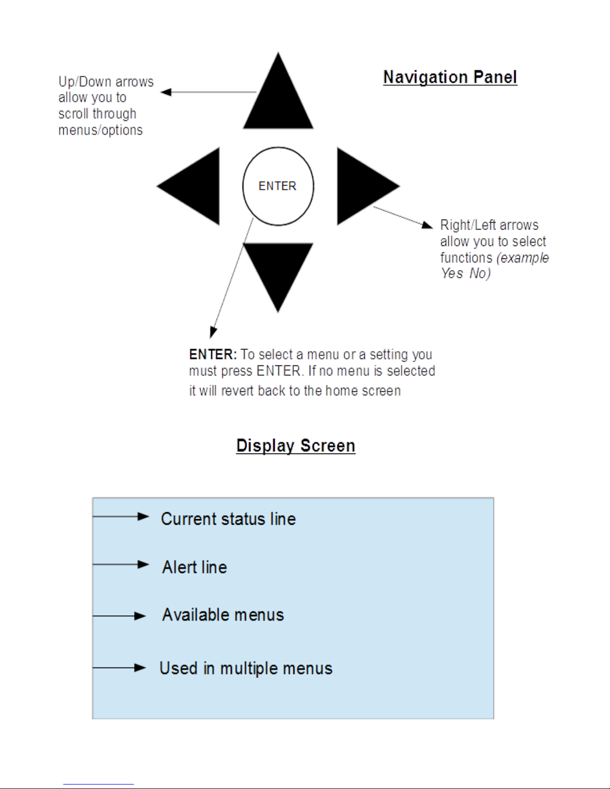
These all can be found in the configuration menu. Use the up and down arrows on the navigation panel to find the configuratio n
menu then press ENTER. Use the left and right arrows to move the cursor/increase the amp hours and the press ENTER when
cursor is on desired position.
Note: Always perform this step when installing new batteries.
Your NexPump is ready for use!
Page 7
7
Control Box Overview
Page 8
8
Page 9
9
System Operating Status
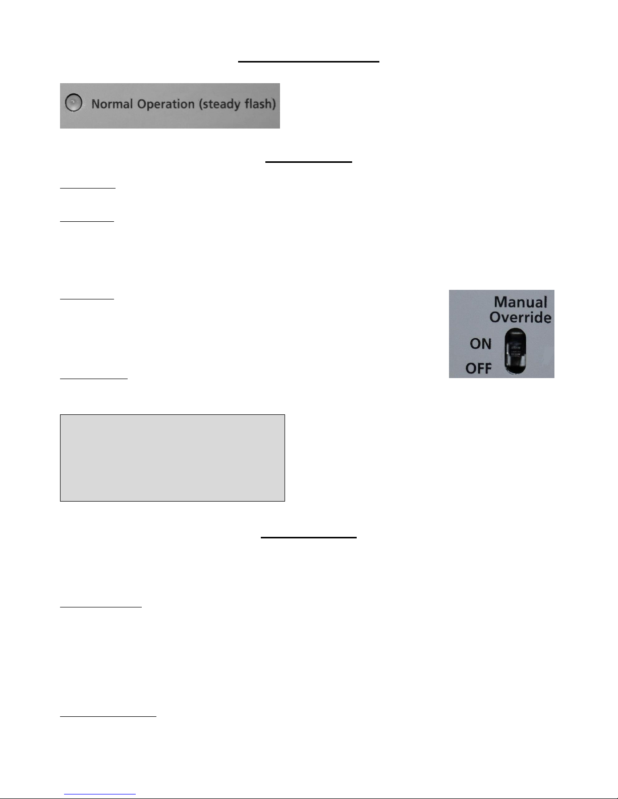
The ‘Normal Operation’ LED must be blinking to indicate the
NexPump system is operating. If it is NOT blinking then there may be
problem with the NexPump system.
Mode Selection
Primary Mode – This should be used when pump is the primary pump.
NexPump WILL NOT display or sound an alarm if pump(s) are activated.
Backup Mode – Should be used when pump is a backup pump
Mode switch in down position. The letter ‘B’ will be blinking in the mode position on display.
NexPump WILL display and sound an alarm if pump(s) are activated.
Note: To select or change a mode it can be found under the configuration menu. Use the left and right arrows and press ENTER
when cursor is over desired position.
Manual Mode – Will manually turn on both pumps
Switch in up position manual mode is ON and in down position manual mode is OFF.
When operating on battery power the NexPump will not calculate battery life remaining.
Clog or vapor lock detection is disabled.
Pumps will turn off for 5 seconds each minute to clear possible vapor lock conditions.
Auto self-test is disabled
Emergency Mode – Will automatically be selected
Mode Emergency will be displayed on the first line of the unit.
Alarm will sound with display indicating the reason NexPump went into the Emergency mode.
Note: The Emergency mode is automatically selected if the NexPump
detects certain conditions. Below is an example of the display when
operating in the emergency mode.
Pump Operation
The NexPump system can only be used with a NexPump specified pump. The Single pump units (Ai Single, Ai Jet) must be
plugged in to the pump 1 slot. The Ai Turbo Pump 1 (red loomed pump) has to be plugged in to the Pump 1 slot. Make sure all
pumps are plugged in properly.
Possible Pump Alerts
Pump is off- pump is not currently pumping
Pump is on- pump is currently running
Pump Activated (backup mode only) - pump needed to run
Pump Problem (Low) - pump may be defective or not working correctly. The system will specify which pump number.
Pump Problem (High) - pump may be defective or not working correctly. The system will specify which pump number.
Pump Problem (Run) - circuit board issue. The system will specify which pump number.
Pump is over hour lifespan- pump has gone over its expected life span of 2500 hours.
Possible Plumbing Alerts
Vapor Lock- This alert indicates there may be air trapped in the discharge plumbing. It may also indicate Sensor 1 is stuck in the
Mode Emergency
Alert 1 of 1
Page 10
10
up position. If a check valve is used, check for a proper vent hole in the pump discharge pipe or check if the vent hole is clogged.
Clog Alerts- This alert indicates a possible clog in the plumbing discharge. Verify the discharge is clear of obstructions. In the
winter it may indicate a frozen discharge pipe.
If Notification is installed
Notification will occur on all pump alerts after approximately five minutes, with the exception of (Pump Activation) which will
occur after approximately thirty minutes.
Clear Pump Alerts
To clear any pump alert use the navigation panel up and down arrows to find the menu clear alarms. Press ENTER to select.
Testing
Pumps are tested on 12 hour self-tests or manual tests.
Pump Hours/Type
This screen has the current stats of your pumps. This can be found in
the information menu.
Pump 1= is the current run hours on pump 1
Pump 2= is the current run hours on pump 2
Type= will either have an ‘H’ or ‘U’ depending on the system.
‘H' = High capacity, 'U' = Ultra capacity)
(00)= indicates how many times the pump has gone over 2500 hours.
The pump is rated at 2500 hours.
Sensor Operations
Sensor Operation
Sensor 1 runs and operates each pump independently. Sensor 2 DOES NOT operate the same as Sensor 1. An active Sensor 2 will
double-beep for approximately sixty seconds before a High Water Alert is triggered. You can test the operation of Sensor 1 by
lifting the float and verifying Pump 1 turns on. Sensor 2 can be tested by lifting the float and verifying a double-beep from the
NexPump System Unit.
Note: The gray sensor should be used as Sensor 1. Sensor 1 should be installed as the lower of the two sensors. The white sensor
should be used for Sensor 2 and should be installed 4-6 inches higher than sensor 1.
Testing
Sensors are continually monitored.
If Notification is installed
Notification will occur on all sensor alerts after approximately five minutes, with the exception of a (High Water Alert) which will
occur in approximately one minute.
Clear Sensor Alerts
Sensor alerts will clear automatically when condition is corrected.
Sensor Displaying Disconnected
Verify the sensors are plugged in and wires are attached to each connector. If the sensors are connected correctly, the sensor may
be defective.
AC Power
AC Power Operation
The NexPump runs on AC power as long as AC is available. During an AC Power outage the NexPump will automatically switch
to battery power. The NexPump will display AC Power problem and sound its alarm. If the alarmed is silenced the system will
still display alerts. When power is restored the alarm will turn off automatically.
Testing
AC Power is continually monitored.
Pump 1=0000H (00)
Type=’H‘
Pump 2=0000H (00)
Type=’H‘
Page 11

11
If Notification is installed
Notification will occur on AC Power loss after approximately thirty minutes.
Clear AC Power Alerts
AC power alerts will clear automatically when condition is corrected.
AC Power Loss
If the NexPump is alerting about an AC Power loss and there is not an issue with the AC Power in your household, you should
check the electrical outlet the NexPump AC Power cord in plugged into with a portable device to check if the electrical outlet is
live. If the electrical outlet is live then there may be an issue with the internal power supply in the NexPump system unit.
IMPORTANT: The power supply is not field serviceable. Do not attempt to disassemble the NexPump or power supply.
Testing
The NexPump schedules an automatic self-test every 12 hours. A
manual test can be done by selecting the menu manual self-test. The
self-test feature will test pumps, battery, electronics, etc. To run a
manual self-test use the up, down arrows and select the menu manual
self-test by pressing ENTER.
Resetting the self-test time can be found in the reset menu or can be
performed with command console on internet versions. Resetting
should be performed at the time you want the self-test to begin.
Once reset the automatic self-test will start at the new time.
To change the self-test time of the system use the left and right
arrows to adjust the time. When on desired time press ENTER to set.
The system self-tests every twelve hours so this will be the time for
AM and PM.
Battery
Battery Specifications
The NexPump requires a deep-cycle marine battery. A 105 amp hour or greater rating is required. This is usually a group 27 or
group 31 deep-cycle marine battery.
Multiple Batteries:
Two batteries may be connected in PARALLEL to increase time on battery power. This configuration is highly recommended.
IMPORTANT: DO NOT CONNECT BATTERIES IN SERIES. CONNECTING MULTIPLE BATTERIES IN SERIES WILL
DAMAGE THE UNIT AND VOID THE WARRANTY.
Testing
Battery is tested on 12 hour self-tests or manual tests. Exceptions: Charge system is active, battery disconnected or battery
replacement alert is active.
If Notification is installed
Notification will occur on a battery disconnected or low battery or battery replacement alert after approximately five (5) minutes.
After an AC Power Outage when running on battery, Notification will occur after approximately thirty (30) minutes.
Manual Self-Test?
Reset Self-Test Time
Hour ? 12 AM/PM
Page 12
12
Battery Connected Improperly
If the battery cables are connected to the wrong posts, the ‘Reversed
Polarity’ red LED will illuminate and an alarm will sound for 'Battery
Problem.’
Note: Correct by reversing the battery cables.
Battery Type
Be sure to select the battery type installed with the system. This
screen can be found under the configuration menu.
Use the left, right arrows and press ENTER when cursor is over
desired position.
Battery Amp Hours
Select the battery amp hours on your battery. If multiple batteries are
connected add the total amp hours together. This can be found in the
configuration menu.
Use the right and left arrows to increase or decrease amp hours.
When on desired number press ENTER.
Battery Charger
The charger should be turned on when the system is first installed or
when replacing the batteries. This can be found in the configuration
menu.
Use the left, right arrows and press ENTER when cursor is over
desired position.
Battery Timer
Batteries have a lifespan and should be replaced when the NexPump
reports this time frame has expired. This should also be reset when
replacing batteries. Defaults for battery type selected. (WET = 1300
days, 3.5 years, AGM = 1600 Days, 4.5 Years)
This can be found in the Reset menu. To select use the left and right
arrows and press ENTER when cursor is over desired position.
Battery Information
This screen can be found under the information menu.
BA=current amp hours of your battery
Batt=battery type
Replace battery= how many days until the system recommends
changing the battery
Battery Type ? W A
W=Wet A=AGM,Gel
Charger ? On Off
Battery Amps ? 105AH
Reset Battery Timer?
Confirm ? Y N
BA=105 AH
E/S=On Batt=Wet
Replace Battery
In: 1350 Days
Page 13
13
Running On Battery Power
When AC power is out the system will alert of an AC power
problem. It will then indicate how many hours are remaining on the
battery. ‘999’ hours is the maximum number displayed. The battery
life monitor calculates the remaining life about four times an hour.
When running on battery power you should closely monitor the
battery life when the hours indicated are ten or below. Battery life
will not be accurate if the battery amp hours are not set correctly
before the power outage began. You can silence this alarm by using
the up, down arrows until the menu silence alarm (24H) appears. To select press ENTER. Once AC power is restored the display
will again display a normal status.
IMPORTANT: When the battery life is calculated at two hours or below, a 'Low Battery' alarm will sound, in addition a
notification will take place if this is the only critical alert. When zero hours are calculated, the pump(s) will no longer operate
to prevent total battery discharge.
Note: If battery life is LOW and battery power is still needed you should connect a replacement battery at this time.
Battery Maintenance:
Check fluid levels, if applicable for each installed battery at least once every six months. To fill fluid levels:
Remove the cell caps of battery. Add distilled water to each cell. If distilled water is not available, tap water with a low mineral
content may be used. NEVER ADD MORE ACID. Fill the battery cell so water is just below the fill cap.
Clean battery posts as needed with a 50/50 solution of water and baking soda or a wire brush. Do not allow any cleaning solution
to enter the battery. Thoroughly dry the terminals and apply petroleum jelly to terminals as needed.
Battery Replacement
The NexPump is constantly monitoring the battery state and will fail
a battery if any one of several tests are not passed within tolerance.
IMPORTANT: Review the safety instructions before proceeding to
replace the battery or batteries.
1. Disconnect each battery, you DO NOT need to power off the
NexPump system unit.
2. Remove each battery and dispose of properly.
3. Connect each new battery. Attach the battery cables to the battery - the BLACK wire to the NEGATIVE (-) post, the RED wire
to the POSITIVE (+) post and tighten securely.
IMPORTANT: Verify the ‘Battery Reverse’ LED is NOT illuminated. If so, reverse connections.
5. Verify battery type and amps under the configuration menu.
6. Turn ON Charger under the configuration menu.
Charger Operation
Charger System Operation:
Charge Rate: 20 Amps
The charging circuit is disabled anytime the battery or electric power
is disconnected or if both pumps are operating. The charge status can
be ‘Full’, ‘Trickle’, ‘Maintain Mode’ and ‘Disabled’. When the
charge is started the display will show ‘Fxx’, where the ‘xx’ is the
actual charge rate in amps. The charge is automatically monitored at
all times. After a full charge is complete the NexPump unit will go
into a trickle charge mode. The display will show ‘Txx’ where the
‘xx’ is the charge rate. When the Trickle mode is complete, the NexPump will go into the ‘Maintain Mode’. In the ‘Maintain
Mode’ charge rates can be very low and may even display ‘M00’ for extended times. It is normal for the 'Maintain Mode’ to run
for multiple days. When the battery is disconnected the charging mode will go into the ‘Disable mode’. The display will show
‘D00’.
Battery Disconnected to Reconnected
Charge Mode F00
Battery Replace
Battery Life 333H
AC Power Problem
Page 14
14
‘S30- The count in seconds when the charge system will start. This allows time for the battery to be reconnected before the
charger starts again.
If Notification is installed
Notification will occur on all charger system alerts after approximately five minutes.
Testing
Charger system is tested on 12 hour self-tests or manual tests. Exceptions: Full or Trickle charge is currently active, AC Power is
off or battery is disconnected.
Turn Charger On
The charger should be turned on when system is first installed or
when replacing the batteries.
This can be found in the configuration menu. Use the left, right
arrows and press ENTER when cursor is over desired position.
Charger Problem
Charger system problems may also be a result of an AC Power problem while a charger system test was active. In that case use the
up, down arrows to find the menu clear alarm and press ENTER. If that is not the case it may indicate a problem with the battery
charger system.
Note: If the battery is completely discharged the NexPump may display the battery disconnected then count down from five
seconds. This may cycle until the battery is at a sufficient level to start the full charge mode. This prevents an overload to the
charge system or battery.
Internal Cooling Fan
Fan Operation
The internal fan does not run continually and is only in use when the charging system is active, any pump is in use or it is in the
test mode, however the fan will continue to run for some time after any pump has run.
Testing
The fan is testing during operation, on self-tests and during manual tests.
If Notification is installed
Notification will occur on any fan alerts after approximately five
minutes.
Fan Problem
A fan problem usually means that the fan is defective and must be
repaired.
Internal Electronics
Primary VRef Alert
A ‘Primary VRef Problem’ indicates an internal hardware problem. This will display as a 'VRef Problem' in the alert line of the
display. The NexPump automatically switches over to its backup VRef if this alert is detected.
Testing
The Primary VRef is continually monitored.
If Notification is installed
Notification will occur on a Primary VRef alert after approximately five minutes.
Clear Primary VRef Alerts
Primary VRef alerts will clear automatically when condition is corrected.
Charger ? On Off
Fan Problem
Page 15
15
Alerts
The NexPump system monitors 38 critical points on the unit. In the case of an alert the system will alarm followed by a
notification if you have that option.
Normal Alerts
Pump Activation
AC Power Loss
Notifications: After approximately thirty minutes
Note: Pump Activation lets you know there may be an issue with your main pump. If you find you have a problem with your main
pump you can switch the NexPump mode to 'Primary' until the main pump problem is corrected.
Critical Alerts
All other alerts
After approximately five minutes, except a High Water Alert, which is approximately one minute.
Silencing or Un-Silencing the Alarm
The alarm can be silenced for normal alerts only. It will silence for
24 hours. A silenced alarm clears automatically after 24 hours.
To silence or unsilence alarm press Enter when on menu ‘Silence
Alarm (24H)’ or ‘unsilence alarm.’
Note: When the alarm is silenced the alerts will blink to notify which
conditions are in the alarm state.
Disabling or Enabling the Alarm
The alarm can be disabled if needed. When disabled, the alarm will
not sound for any reason. The alarm will stay disabled for five days
and automatically be enabled after that time. You can enable the
alarm before the five day period by selecting the Enable Alarm menu
and pressing ENTER.
Note: All notifications will take place while the alarm is disabled,
disabling the alarm simply turns off the sound.
Alert History
Under the information menu you can retrieve the history of the last
ten alerts registered. The date and time will be displayed with the
alert.
To find the alert history select the information menu and once on the
screen ‘Alert History Display’ use the left and right arrows to move
the cursor then press ENTER.
Displaying Alerts:
Below are two examples of what the display will look like when there are alerts on the NexPump. Line two of the display will
show you each alert approximately every three seconds. The first example will let you know the number of alerts and the current
number it will be displaying. The format will be 'Alert x of x'. The second example is the actual alert that follows the first
example.
Alert History
Display ? Y N
Silence Alarm? (24H)
Disable Alarm? (5D)
Page 16
16
Clearing, Silencing, Disabling Alarms
To clear the alarm use the up, down arrows to find the menu clear
alarm. To select press ENTER.
The alarm can be silenced for normal alerts only. These include
Pump Activation and AC Power Loss. A silenced alarm clears
automatically after twenty four hours.
To silence the alarm use the up, down arrows to find the menu
silence alarm. To select press ENTER.
Note: When the alarm is silenced the alerts will blink to notify which
conditions are in the alarm state.
If the alarm is silenced you can unsilence it by selecting the menu
unsilence alarm.
To unsilence the alarm use the up, down arrows to find the menu
unsilence alarm. To select press ENTER.
The alarm can be disabled if needed. When disabled, the alarm will
not sound for any reason. The alarm will stay disabled for five days
and automatically be enabled after that time. You can enable the
alarm before the five day period.
To disable the alarm use the up, down arrows to find the menu
disable alarm. To select press ENTER. It will ask to confirm
disabling the alarm, use the left, right arrows to select desired
position then press ENTER.
Note: All notifications will take place while the alarm is disabled,
disabling the alarm simply turns off the sound.
Alert 1 of 1
Sensor 2 Problem
Clear Alarm?
Silence Alarm? (24H)
Disable Alarm? (5D)
UnSilence Alarm?
Page 17
17
If the alarm is disabled you can enable it by selecting the menu
enable alarm.
To enable the alarm use the up, down arrows to find the menu enable
alarm. To select press ENTER.
Configuration Menu
Note: If you have a notification unit please see the Notification Guide for additional screens.
The configuration menu allows unit specific information to be input
into the system. Battery, amps, charger, etc.
To select the configuration menu use the up, down arrows until you
see configuration menu on the third display line then press ENTER.
Select the battery type currently on your system. Press ENTER when
cursor is over desired position.
Select the battery amp hours on your battery. If multiple batteries are
connected add the total amp hours together. Use the right and left
arrows to increase or decrease amp hours. When on desired number
press ENTER.
Charger will turn on the battery charger if selected. It is
recommended to turn on the charger when system is first installed or
when replacing batteries. Press ENTER when cursor is over desired
position.
Battery Type ? W A
W=Wet A=AGM,Gel
Battery Amps ? 105AH
Charger ? On Off
Configuration Menu?
Enable Alarm?
Page 18
18
There are two types of modes to select.
Primary Mode – Should be used when pump is the primary pump.
NexPump WILL NOT display or sound an alert if pump(s) are
activated.
Backup Mode - Used when pump is a backup pump. NexPump
WILL display and sound an alarm if pump(s) are activated.
To select a mode use the left and right arrows and press ENTER
when cursor is over desired position.
Information Menu
Note: If you have a notification unit please see the Notification Guide for additional screens.
The information menu has specific information on your system
including stats, serial number, alert history, etc.
To select the information menu use the up, down arrows until you
see information menu on the third display line, then press ENTER.
First line will display current system type.
SN= stands for the serial number of the system
The last line will indicate the current version of the system.
This screen has the current stats of your pumps
Pump 1= is the current run hours on pump 1
Pump 2= is the current run hours on pump 2
Type= will either have an ‘H’ or ‘U’ depending on the system.
‘H' = High capacity, 'U' = Ultra capacity)
(00)= indicates how many times the pump has gone over 2500 hours.
The pump is rated at 2500 hours.
CPU=current power up days of the system
TPU= total power up days of the system
Auto Tests= amount of self-tests the system has preformed
Man Tests= amount of manual tests the system has preformed
Man Tests= amount of manual tests the system has preformed
Mode ? Back Prim
System Type
SN-NPB0000000
Version Type
Pump 1=0000H (00)
Type=’H‘
Pump 2=0000H (00)
Type=’H‘
CPU=00123 Days
TPU=00123 Days
Auto Tests=00123
Man Tests=00123
Information Menu?
Page 19
19
BA=current amp hours of your battery
E/S=empty sump option
Batt=battery type
Replace battery= how many days until the system recommends
changing the battery
Current time and date set to the system.
Note: Notification systems will automatically set the date and time.
Alert history will display the last ten alerts of the system. It will
display the alert as well as the date and time the alert occurred.
Advanced Menu
Note: If you have a notification unit please see the Notification Guide for additional screens.
To select the advanced menu use the up, down arrows until you see
advanced menu on the third display line, then press ENTER.
The empty sump option will pump the water out of the pit after each
12 hour self-test. This is useful so no standing water is left in the pit
especially when the NexPump is a backup pump for another pump
that could corrode.
To select use the left and right arrows and press ENTER when cursor
is over desired position.
Alert History
Display ? Y N
Time=12:12AM/PM
Date=01-01-18
BA=105 AH
E/S=On Batt=Wet
Replace Battery
In: 1350 Days
Empty Sump ? On Off
Advanced Menu?
Page 20
20
Reset Menu
Note: If you have a notification unit please see the Notification Guide for additional screens.
The reset menu allows you to change or reset the time, date, timers,
etc.
To select the reset menu use the up, down arrows until you see reset
menu on the third display line, then press ENTER.
This will allow you to set the current time on the system. If you want
to set the time select the ‘Y’ and use the up, down arrows to adjust
the time.
Note: the up, down arrows will adjust the time and the left, right
arrows will move the cursor.
This will allow you to set the current date on the system. If you want
to set the date select the ‘Y’ and use the up, down arrows to adjust
the time.
Note: the up, down arrows will adjust the time and the left, right
arrows will move the cursor.
To change the self-test time of the system use the left and right
arrows to adjust the time. When on desired time press ENTER to set.
The system self-tests every twelve hours so this will be the time for
AM and PM.
Batteries have a lifespan and should be replaced when the NexPump
reports this time frame has expired. This should also be reset when
replacing batteries. Defaults for battery type selected. (WET = 1300
days, 3.5 years, AGM = 1600 Days, 4.5 Years)
To select use the left and right arrows and press ENTER when cursor
is over desired position.
Set Time ? Y N
Time=12:12 AM/PM
Set Date ? Y N
Date=01-01-18
Reset Self-Test Time
Hour ? 12 AM/PM
Reset Battery Timer?
Confirm ? Y N
Reset Menu?
Page 21

21
Quick Reference Guide
Power OFF
1. Disconnect Battery
a. Disconnect (+) Positive Cable (Red)
b. Disconnect (-) Negative Cable (Black)
2. Unplug NexPump’s AC Power Cord
Power ON
1. Plug in the AC Power Cord FIRST!
2. Connect Battery
a. Connect (-) Negative Cable (Black)
b. Connect (+) Positive Cable (Red)
c. Verify Battery Reverse Indicator
Manual Override Mode
1. Set Override switch to up position.
2. Pump(s) should turn on.
3. Battery life will not be calculated.
4. Clog or vapor lock detection is disabled.
5. Set Override switch to down position to turn pump(s) off and return to normal.
Clear Alarm(s)
To clear the alarm use the up, down arrows to find the menu clear alarm. To select press ENTER.
Silence Alarm
To silence the alarm use the up, down arrows to find the menu silence alarm (24H). To select press ENTER.
Note: Automatically cleared after 24 hours. Alarm will only silence for 'Pump Activated' and ‘AC Power Problems Alarms
UnSilence Alarm
If the alarm is silenced you can unsilence it by selecting the menu unsilence alarm.
To unsilence the alarm use the up, down arrows to find the menu unsilence alarm. To select press ENTER.
Manual Test
To run a manual self-test use the up, down arrows to find the menu manual self-test. To select press ENTER.
Retrieve Serial Number
The NexPump serial number is located on a card on the top of the unit or a sticker on the rear of the unit.
Battery Amp Hours Setup
1. Use the up, down arrows to find the configuration menu. Select it by pressing ENTER.
2. Wait for the screen ‘Battery Amps?’
3. Use the left and right arrows to increase or decrease the amps. Press ENTER when on correct amps.
Stats Information
The stats can be found under the information menu. Use the up and down arrows to find the information menu. Select it by
pressing ENTER.
Disable Alarm
To disable the alarm use the up and down arrows to find disable alarm (5D). Select it by pressing ENTER. To confirm it use the
left and right arrows until the cursor is over the desired position. Select it by pressing ENTER.
Enable Alarm
If the alarm is disabled you can re-enable it by using the up and down arrows to find enable alarm. Select it by pressing ENTER.
Reset Battery Timer
1. Use the up, down arrows to find the reset menu. Select it by pressing ENTER.
2. Wait for the screen ‘Reset Battery Timer Confirm?’
3. Use the left and right arrows until the cursor is over the desired position. Select it by pressing ENTER.
Page 22

22
NexPump Specifications
Maximum input/output levels
Input: AC
Ai Extreme, Ai Dual
Full Load 115 Volts AC @ 8.5 amps
Standby Load 115 Volts AC @ 0.17 amps
Ai Single
Full Load 115 Volts AC @ 4.5 amps
Standby Load 115 Volts AC @ 0.17 amps
Charge Output
20 Amps
Operating Temperature
9ºC~38ºC (48ºF~100ºF)
Storage Temperature
0ºC~38ºC (32ºF~100ºF)
Page 23

23
LIMITED WARRANTY:
This NexPump, Inc. product is warranted against defects in workmanship and materials. If any failure of these components,
resulting from a defect in either workmanship or material shall occur under normal use within THREE YEARS (3) from the
original date of purchase for Ai Extreme Series Pumps and Ai Dual or under normal use within TWO YEARS (2) from the
original date of purchase for the Ai Single, such failure shall be corrected free of charge to the original purchaser by repa ir or, at
NexPump's sole option, replacement of the defective part or parts.
No charge shall be made for labor or services performed during the said warranty period providing the defective product is
sent prepaid to our Authorized Service Station. NexPump, Inc. will either repair or at its sole option, replace any such part except
for fuses, circuit breakers under normal and proper use. This warranty does not cover High Capacity pumps that have exceeded
2500.0 hours of operating time or Ultra Capacity pumps that have exceeded 2500.0 hours of operating time and does not cover
equipment, which had been tampered with in any way, or to damage caused by accident, negligence, alteration, misapplication or
natural disasters.
This product must be returned transportation prepaid, properly packed and insured. NexPump, Inc. bears transportation cost of
the repaired product back to the purchaser. This warranty applied only to the original purchaser.
NO OTHER WARRANTIES ARE EXPRESSED OR IMPLIED. NEXPUMP, INC. IS NOT LIABLE FOR
CONSEQUENTIAL DAMAGES.
EXCEPT AS SET FORTH HEREIN, THERE ARE NO WARRANTIES, EXPRESS OR IMPLIED, WITH RESPECT TO
NEXPUMP PRODUCTS. NEXPUMP, INC. EXPRESSLY EXCLUDES AND DISCLAIMS ANY IMPLIED WARRANTY OF
MERCHANTABILITY AND ANY WARRANTIES OF FITNESS FOR A PARTICULAR PURPOSE, APPLICATION OR USE.
UNDER NO CIRCUMSTANCES WILL THE COMPANY BE LIABLE FOR SPECIAL, INCIDENTAL OR CONSEQUENTIAL
DAMAGES, WHETHER SUCH DAMAGES ARE SOUGHT IN CONTRACT, IN TORT (INCLUDING BUT NOT LIMITED
TO NEGLIGENCE AND STRICT LIABILITY) OR OTHERWISE, AND THE COMPANY'S LIABILITY SHALL IN NO
EVENT EXCEED THE PURCHASE PRICE OF THE NEXPUMP PRODUCTS ON WHICH SUCH LIABILITY IS BASED.
Page 24
24
Page 25
25
Page 26
26
 Loading...