

Page 1
User Manual
Page 1 of 15
Page 2

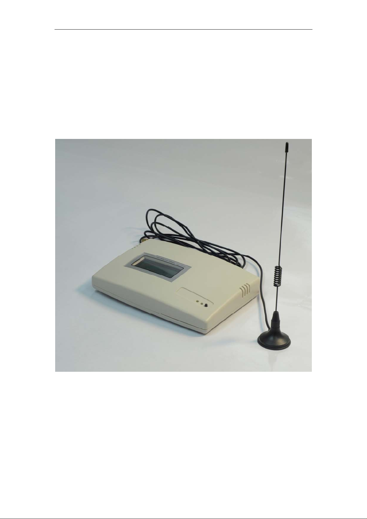
Product Introduction
Congratulations on purchasing of our Fixed Wireless Terminal. Before using this terminal, please
kindly read this user guide carefully.
This is our new design, which uses GSM networks to operate. You can dial the local calls,
domestic and international calls with this Terminal connecting with a common wired desktop
phone and a standard SIM card. It is widely used in these areas:
Remote country
Mountains
Dwelling house with weak signals
Public telephone shops
Offices
Removable places such as Ships, Trains, and Long distance buses
Our wireless Terminal also has these characteristics as below:
Easy to install
Easy to operation
Powerful capacity of signals receiving
Clear talking setting
Long using life
Steady performance
Key Technical Specifications
Following are the key technical specifications of this Terminal:
1. Networks support: GSM 850/900/1800/1900MHz
2. Frequency range:
TX Frequency Range:
880~915MHz,1710~1785MHz
824~849MHz,1850~1910MHz
RX Frequency Range:
925~960MHz,1805~1880MHz
869~894MHz,1930~1990MHz
Voltage: DC 5V
3.
4.
Power consumption:
Static≤25MA emission≤500MA
5. Peak power consumption: 1W/2W
6. Receive sensitivity: -104db
Key functions
The key functions of the Terminal are list as below:
1. Can dial the local calls, mobile calls, international calls and special free calls;
2. Password authority administrable;
Page 2 of 15
Page 3

3. volume adjustable;
4. Time and Date setting and getting
Cautions and Storage
Cautions
1. This terminal should not be used at garage, oil storage, and chemical plant or near to any
inflammable or explosive substance.
2. This terminal should be avoided in the hospital. It will interfere with medical electronic
equipments such as pacemaker and audiphones.
3. If it is found that the terminal is not successful in login onto network, please check whether
the SIM card or antenna is well installed.
4. It is blocked to touch the antenna when the Terminal is being used. (Being making calls or
receiving calls), otherwise the terminal will be damaged. This kind of damage is beyond
the range of warranty.
5. When the terminal is being used, it should be placed where signal is strong enough. In order
to ensure good voice quality, the terminal should be far from other electronic equipment.
6. Don’t use chemic substance to clean the terminal, but use dry soft cloth to clean it.
7. Don't disassemble the terminal by yourself. If there is any problem, please contract the
authorized personnel.
Storage:
1. The terminal that is packed or not could piled up no more than 10 layers.
2. The terminal should be saved in ventilate and dry place.
3. Don’t knock the terminal to avoid breaking the case.
This user guide provides information on the use and
operation of your FWT. Kindly read all the information
contained in this user guide carefully prior to using the
Phone. This will help you in getting the best
performance and shall prevent any unintended
damage to the Phone. Check the contents of the box
as per the packing list and report any discrepancies
Do’s & Don’ts
z Do not clean the FWT while in operation. Before attempting to clean the FWT,
turn the FWT off, disconnect the external power adapter. Use a Damp cloth for
cleaning. Do not use liquid or aerosol cleaners.
immediately to the store from where Phone has been
purchased.
z Do not hold the antenn a. This may affect call quality and cause FWT to operate
at unintended power levels.
z Keep the antenna free from obstructions and position the antenna straight up.
This will ensure best call quality.
Page 3 of 15
Page 4

z Do not use a damaged antenna. Have this replaced through a qualified
technician. Use only antenna approved by the manufacturer. Unapproved
antenna may impair the call quality as well as cause damage to the FWT.
z Do not attempt to change the security codes or components. User is responsible
for any consequences arising out of such attempt.
z Avoid shock or impact. Rough handling can cause damage to the FWT body and
internal circuits.
z Do not paint.
z During lightening do not touch power plug or FWT line. This can cause Electric
shock, even death. Do not touch the external antenna.
z Your FWT is to work with 100-240V AC. Check the voltage before connecting.
z Do not plug many power cords in the outlet.
z Do not touch the plug with wet hands. Always grasp and pull the plug, not the
cord. Do not put heavy things on the power cord or bend it too much.
z If the FWT is not working for any reason, do not attempt to repair it. The FWT
should be serviced by qualified service personnel only.
z Place the FWT and the power supply in a properly ventilated place.
z Do not place the FWT near high temperature objects, under direct sunlight, near
source of water, near fire or near inflammable and explosive materials.
z Do not place any articles over the FWT.
z Place the FWT in a dry place and do not expose to moisture.
z Place the FWT away from other electronic devices like TV and Radio to avoid
interference.
z For a better reception, do not place the Instrument in a building with iron or metal
roof.
z Hospitals or health care facilities may use equipment which is sensitive to Radio
Frequencies. Please ensure that your FWT is turned “OFF” while in the vicinity of
such facilities.
z Do not use the FWT in designated “No Fixed FWT Use” area.
Page 4 of 15
Page 5
Connect the terminal
Connecting Your Service Provider
To use the networks services available in you terminal, you will need to sign up with wirelesses
provider and purchase a SIM (Subscriber Identity Module) Card or purchase a prepaid SIM card.
In many cases, the wireless provider will make available descriptions of its services and
instructions for using its features. Wireless provider may differ in their support of features. Before
you sigh up, make sure a wireless provider support the features that you need.
Installing the Antenna
To choose a proper place for the antenna is the first and very important step for antenna
installing. You can use your mobile phone to search for the place where the strongest signal is.
Then put the antenna here.
Please do not make the antenna too close to the terminal. It will disturb the signal of the
terminal.
Please do not make the antenna and the terminal too close to the TV set, computer, and
radiogram. It will disturb the signal of the terminal.
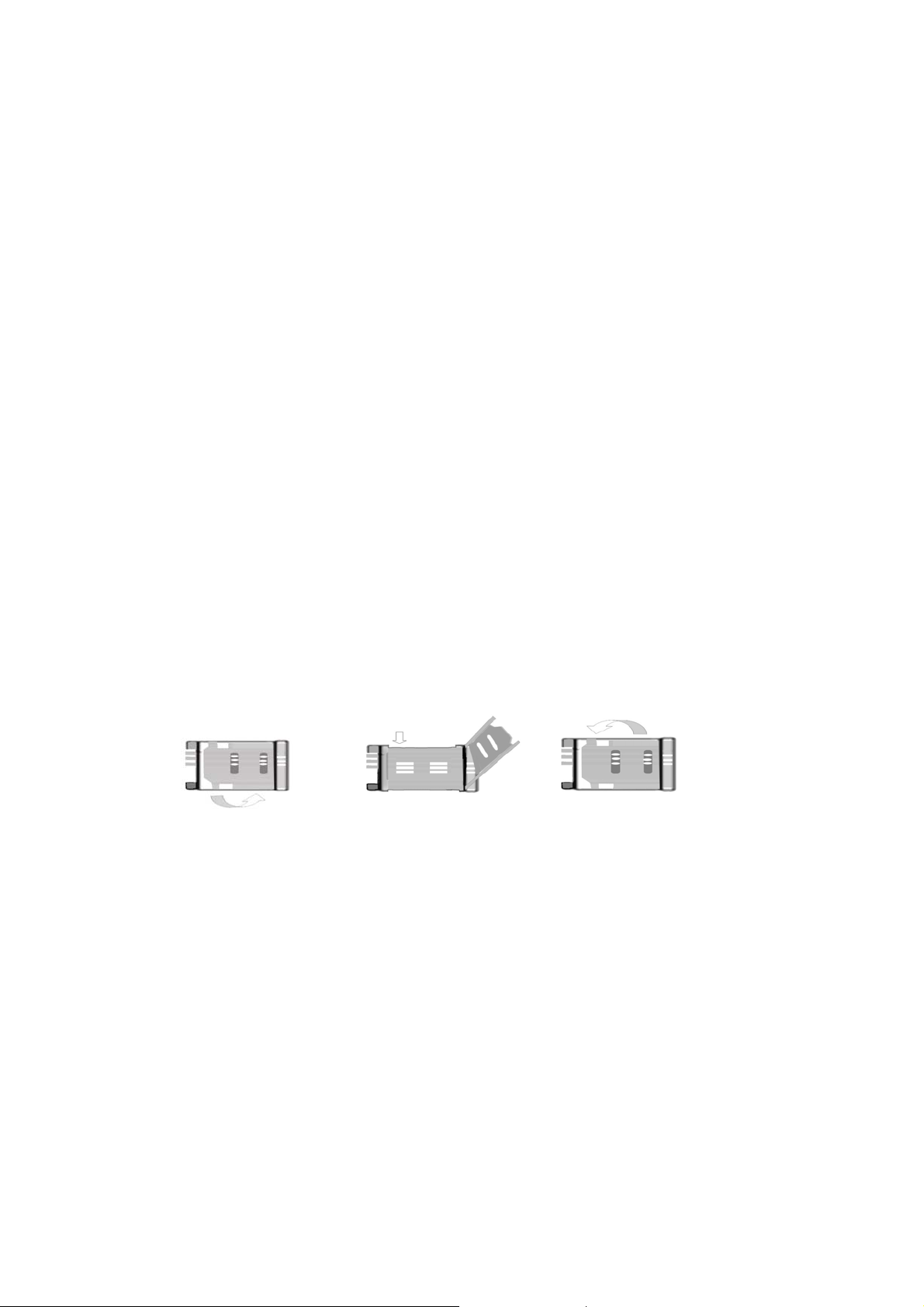
Inserting a SIM Card
Make sure the terminal is switched off and the AC adapter is unplugged: insert the SIM card only
when the terminal is switched off and the AC adapter is unplugged. Follow the instructions below
to insert a SIM Card into the terminal.
1). Screw off the screw of SIM card case, and open the cover.
2). Slide back the SIM card door and lift it up.
3). Slide the SIM card into the SIM door making sure that the clipped corner of the SIM
card lines up with the clipped corner of the SIM holder.
4). Close the SIM card door and slide it to lock the SIM card in place.
5). Replace the cover of SIM card case and fixes it with a screw.
Connecting your terminal with desktop phone
If you want to use the terminal to make calls, you should connect the terminal with a common
wired desktop phone.
Page 5 of 15
Page 6

There are two communicatio n portals at th e back of the t erminal. You can connect desktop phones
with our terminal. It’s very easy to connect the phone and terminal, just need a common
communication cable.
Page 6 of 15
Page 7

Operation and Setting
1. Power on/off the FWT
There is a toggle switch in the back FWT, power on the FWT after switch on this switch.
1.1 LED light and Infomation after power on
Red LED: Power LED Indicator,It will LED ON permanent after power on.
Greed LED: Network Indicator, It will flash after registering on the network.
Reset Button: after press this button, the FWT will reset.
Green LED light activity Status
ON
OFF LED OFF
The below table show the mean of display information after power on the FWT
inf:0
inf:1
inf:2
inf:3
inf:17~25
INPUT PIN:
2. Date and Time setting and query
2.1 Date Query command: **1010*1#.
Response Confirmation Tone if success and display Year,Month,Day.
The below photo is a sample.
LED ON permanent FWT is switched ON but not registered on the network
LED Flashing slowly
LED Flashing rapidly
Without Sim card Greend Indicator
Limited Service
No Service
Searching networking
Sim Card error
Opened SIM Card PIN Function, PLS Close it.
FWT is switched ON and registered on the network,
but no Call is in progress (Idle mode)
FWT is switched ON and registered on the network,
and a Call is in progress
LED ON permanent
LED ON permanent
LED ON permanent
LED ON permanent
LED ON permanent
Page 7 of 15
Page 8

2.2 Time Query Command: **1010*2#.
Response Confirmation Tone if success and display hour and minute.
The below photo is a sample response.
2.3 Set time command: **2011*MMMM*YYMMDDHHMM#
Response Confirmation Tone if success.
MMMM is password, default password is 0505.
YYMMDDHHMM is year (YY) month (MM) day (DD) hour (HH) minute (MM).
2.4 Version Query Command: **1010*0#
Response Confirmation Tone if success and display current Software version number
The below photo is a sample response.
Page 8 of 15
Page 9

1.Dialing:
Pick up handset, input desired number after hearing dialing tone;
Press “#” key after input desired number to dial it faster, it’ll be dialed out
automatically after 4 seconds if you don’t press “#” key;
The LCD will display below photo
2.Pick up phone call:
When the terminal rings that means there is new call come, the LCD will display
above photo, pick up handset to proceed conversation, it will show the below photo.
Page 9 of 15
Page 10

Return handset to the base after conversation completed. The LCD show below
photo, it showes the total call timer.
4. Speical setting command.
MMMM is previous
password and
NNNN is new
password, default
password is 0505.
MMMM is
password,
YYMMDDHHMM is
year (YY) month
(MM) day (DD)
hour (HH) minute
(MM).
The command is
used to obtain
setting
authorization, and it
Password
Authority
Management
Function
Change password
Set Time
Set command
authority
**2010*MMMM*NN
NN*NNNN#
**2011*MMMM*YY
MMDDHHMM#
**2012*MMMM#
Response
Confirmation
Tone if success
Response
Confirmation
Tone if success
Page 10 of 15
Page 11

will lose efficacy in
another minute.
RESTORE
FACTORY
SETTINGS
The following commands need customer to gain some setting permissions. (The red letter ones )
Volume setting **1020*N#
Set 100ms flash
hang up.
Enable ring back
tone
Function setting
Disable ring back
tone
Enable Caller ID
blocking
Disable Caller ID
blocking
Display numbers
in DTMF mode
Query number
Call in and call
out
display mode
Set numbers dial
out delayed
**2030*1234#
**1050*1#
**1060*1#
**1060*0#
**1100*1#
**1100*0#
**1110*0#
**1110*2#
**1120*T#
Response
Confirmation
Tone if success
Response
Confirmation
Tone if
success
Response
Confirmation
Tone if
success
Response
Confirmation
Tone if
success
Response
Confirmation
Tone if
success
Response
Confirmation
Tone if
success
Response
Confirmation
Tone if
success
Response
Confirmation
Tone if
success
Response
Confirmation
Tone if
success and
show up as
10X
Response
Confirmation
Tone if
success
Restore default
value.
N is volume level
1-8,Default level is
level 5.
Default value is
100ms flash hang
up.
Play ring back tone
when you call out
but did not’ getting
through.
This option is ON
by default.
No all SIM card
support this
function.
Default value
Show as DTMF by
default.
Value 0 means
DTMF mode.
T is delayed time.
Its value is 1~9
second. The
minimum time is 1
second, default
value is 5 second.
Page 11 of 15
Page 12

Fixed dialling
function
Query delay
seconds and dial
out after pressing
call number
Disable
international
phone call out
Enable
international
phone call out
Query
international
phone call
restriction
Restrict all
incoming calls
Cancel all
incoming call
restriction
Query all
incoming calls
setting
Set incoming call
blacklist
**1120*0#
**1140*1#
**1140*0#
**1140*2#
**1141*1#
**1141*0#
**1141*2#
**1142*M*N#
Response
Confirmation
Tone if
success and
show up as
2XX
Response
Confirmation
Tone if
success
Response
Confirmation
Tone if
success
Response
Confirmation
Tone if
success and
show up as
40X
Response
Confirmation
Tone if
success
Response
Confirmation
Tone if
success
Response
Confirmation
Tone if
success and
show up as
40X
Response
Confirmation
Tone if
success
XX means delayed
time duration. Unit:
second, e.g. 03
means 3 seconds.
To restrict overseas
call. Overseas call
are enabled by
default.
Enable
international phone
call out
If value of X is 1, it
means there is
international call
restriction;
If value of X is 0, it
means there is no
international call
restriction.
All incoming calls
are barred. There is
no restriction by
default.
No incoming call is
barred.
If value of X is 1, it
means there is
international call
restriction;
If value of X is 0, it
means there is no
international call
restriction.
M is sequence
number, value
ranges from 0-9,
and means there
are 10 groups of
number.
N means number
segment, maximum
Page 12 of 15
Page 13

Clear all incoming
call blacklist
Query incoming
call white list
Set fixed
restricted number
Clear all fixed
restricted
numbers
Inquire fixed
restricted number
**1142*#
**1143*M*#
**1144*M*N#
**1144*#
**1145*M#
length is 11 digits.
Response
Confirmation
Tone if
success
Response
Confirmation
Tone if
success
and show up
as XXNNN
Response
Confirmation
Tone if
success
Response
Confirmation
Tone if
success
Response
Confirmation
Tone if
success and
show up as
XXNNN…
Clear all incoming
call blacklist
M is sequence
number, value
ranges from 0-9,
means the
sequence number
in 10 numbers.
It is showed as
XXNNN…,
XX is sequence
number, ranges
from 0-9; its value
is the same as that
of M.
NNN is restricted
number segment.
M is sequence
number, ranges
from 0-9; it means
you can set 10
telephone
numbers.
N is number
segment, the length
is no more than 11
digits.
Clear all fixed
restricted numbers
M is sequence
number, ranges
from 0-9; it means
you are inquiring
the Nth phone
number in the 10
numbers, and
showed as
XXNNN…, XX is
sequence number,
ranges from 0-9; its
value is the same
Page 13 of 15
Page 14

as M.
N
NNN… means
restricted number
segment.
Packing List
With the Fixed Wireless Terminal, there are some accessories. When you get the terminal please
check them and to see whether you have all of them. Please contact us or call the distributor in
your area to hand back the absent parts if you find that you lack one of them as below:
ame Quantity Remark
DC adapter
Special antenna
User Manual
1pcs DC5V/1A
1pcs
1pcs English
Page 14 of 15
Page 15

FCC Warning:
This device complies with part 15 of the FCC Rules. Operation is subject to the following
two conditions: (1) This device may not cause harmful interference, and (2) this device
must accept any interference received, including interference that may cause undesired
operation.
Any Changes or modifications not expressly approved by the party responsible for
compliance could void the user’s authority to operate the equipment.
FCC Radiation Exposure Statement:
This equipment complies with FCC radiation exposure limits set forth for an uncontrolled
environment .This equipment should be installed and operated with minimum distance 1
m between the radiator & your body.
This transmitter must not be co-located or operating in conjunction with any other antenna
or transmitter.
Page 15 of 15
 Loading...