

Page 1

STM Series
STM S118 Sub Module
STM B112 Bass Module
STM M46 Main Module
STM M28 Omni Module
Setup Manual
STM Series User Manual V1.02
Date: 2016/03/25
Page 2
Page 2/62 PLEASE READ CAREFULLY BEFORE PROCEEDING
PLEASE READ CAREFULLY BEFORE PROCEEDING
BASIC PRECAUTIONS
Do not open the speaker system or attempt to disassemble the internal parts or modify them in any way.
The speaker system contains no user-serviceable parts. If it should appear to be malfunctioning or damaged,
discontinue use immediately and have it inspected by qualified NEXO service personnel.
Water exposure: Do not expose the speaker system to direct rain; do not use it near water or in wet
conditions. Do not place containers with liquid on speaker system as they might spill into openings. If any
liquid such as water seeps into the speaker system, have it inspected by qualified NEXO personnel.
SYSTEM DEPLOYMENT SAFETY RULES
Read User Manual before deployment. Before use of enclosed speaker system, please ensure
that anyone involved in system deployment understands the rigging – stacking – pole mounting
safety rules as described in the speaker system User Manual. Failure to do this exposes
people to potential injury or death.
Always consult qualified NEXO personnel if the device installation requires construction work and make sure
to observe the following precautions:
Mounting precautions
- choose mounting hardware and an installation location that can support the weight of the speaker system;
- do not use speaker system handles for suspended installation;
- do not expose speaker system to excessive dust or vibration, or extreme cold or heat to prevent possibility
of component damage;
- do not place the speaker system in an unstable position from which it might fall accidentally;
- if speaker systems uses a stand, ensure that stand specifications are adapted, and that stand height does
not exceed 1.40m/55”; never move the stand while the speaker is in position.
Connection and powering precautions
- remove all connected cables before moving the speaker system;
- turn off AC power of all power amplifier units before connecting the speaker system;
- when turning on the AC power to the audio system, always turn on the power amplifier last; when turning
the AC power off, always turn off the power amplifier first;
- when used in cold conditions, a gradual power ramp up should applied to the system on an 5 mn period to
allow the loudspeaker components to stabilize during the very first minutes of usage.
Inspect the speaker system periodically.
Page 3

PLEASE READ CAREFULLY BEFORE PROCEEDING Page 3/62
SAFETY INSTRUCTIONS FOR NEXO TD CONTROLLERS
NXAMP4x1 AND NXAMP4x4 POWERED CONTROLLERS ARE CLASS 1 APPARATUS AND
MUST BE EARTHED.
THE GREEN AND YELLOW WIRE OF THE MAINS CORD MUST ALWAYS BE CONNECTED TO AN
INSTALLATION SAFETY EARTH OR GROUND. THE EARTH IS ESSENTIAL FOR PERSONAL SAFETY AS
WELL AS THE CORRECT OPERATION OF THE SYSTEM, AND IS INTERNALLY CONNECTED TO ALL
EXPOSED METAL SURFACES.
- Read these instructions.
- Keep these instructions.
- Heed all warnings.
- Follow all instructions.
- Do not use this apparatus near water.
- Clean only with dry cloth.
- Do not block any ventilation openings. Install in accordance with the manufacturer’s instructions.
- Do not install near any heat sources such as radiators, heat registers, stoves, or other apparatus (including
amplifiers) that produce heat.
- Do not defeat the safety purpose of the polarized or grounding-type plug. A polarized plug has two blades
with one wider than the other. A grounding type plug has two blades and a third grounding prong. The wide
blade and the third prong are provided for your safety. If the provided plug does not fit into your outlet,
consult an electrician for replacement of the obsolete outlet. (US market)
- Protect the power cord from being walked on or pinched particularly at plugs, convenience receptacles,
and the point where they exit from the apparatus.
- Only use attachments/accessories specified by the manufacturer.
- Unplug this apparatus during lightning storms or when unused for long periods of time.
- Refer all servicing to qualified service personnel. Servicing is required when the apparatus has been
damaged in any way, such as power-supply cord or plug is damaged, liquid has been spilled or objects
have fallen into the apparatus, the apparatus has been exposed to rain or moisture, does not operate
normally, or has been dropped.
Page 4
Page 4/62 PLEASE READ CAREFULLY BEFORE PROCEEDING
HIGH SOUND PRESSURE LEVELS
Exposure to extremely high noise levels may cause permanent hearing loss. Individuals vary
considerably in susceptibility to noise-induced hearing loss but nearly everyone will lose some
hearing if exposed to sufficiently intense noise for a sufficient period of time. The U.S.
Government’s Occupational and Health Administration (OSHA) has specified the following
permissible noise level exposures: Sound Duration Per
Day In Hours
Sound Level dBA, Slow Response
8
90 6 92 4 95 3 97
2
100
1 ½
102 1 105 ½ 110
¼ or less
115
According to OSHA, any exposure in excess of the above permissible limits could result in some hearing loss.
Ear plugs or protectors to the ear canals or over the ears must be worn when operating this amplification system
in order to prevent permanent hearing loss, if exposure is in excess of the limits as set forth above. To ensure
against potentially dangerous exposure to high sound pressure levels, it is recommended that all persons
exposed to equipment capable of producing high sound pressure levels such as this amplification system be
protected by hearing protectors while this unit is in operation.
DISPOSAL OF OLD ELECTRICAL & ELECTRONIC EQUIPMENT
This symbol on the product or on its packaging indicates that it shall not be treated as
household waste. Instead it shall be handed over to the applicable collection point for the
recycling of electrical and electronic equipment. By ensuring this product is disposed of
correctly, you will help prevent potential negative consequence for the environment and
human health, which could otherwise be caused by inappropriate waste handling of this
product. The recycling of materials will help to conserve natural resources. For more
detailed information about recycling of this product, please contact your local city office,
your household waste disposal service or the shop where you purchased the product.
Page 5

CONTENTS Page 5/62
CONTENTS
PLEASE READ CAREFULLY BEFORE PROCEEDING ........................................................ 2
CONTENTS ............................................................................................................................. 5
1 Introduction ..................................................................................................................... 7
2 STM Connectors and cabling ........................................................................................ 9
2.1 Speaker modules connection .................................................................................... 9
2.2 STM cabling ............................................................................................................ 11
3 STM and NUAR NEXO Universal Rack........................................................................ 12
3.1 NUAR Components ................................................................ ................................. 12
3.1.1 NXAMP4x4 .......................................................................................................... 12
3.1.2 DMU (Digital Metering Unit) ................................................................................. 13
3.1.3 DPU (Digital Patching Unit) .................................................................................. 13
3.1.4 Digital audio networking ....................................................................................... 14
3.1.5 Power box ............................................................................................................ 14
3.1.6 Rack ..................................................................................................................... 14
3.2 STM Setups ............................................................................................................. 14
3.2.1 NEXO STM configurations ................................................................................... 14
3.2.2 Custom STM configurations ................................................................................. 14
STM and NUAR configurations .......................................................................................... 15
4 NS-1 Simulation software ............................................................................................ 21
5 STM system deployment procedure ........................................................................... 22
5.1 SAFETY FIRST ....................................................................................................... 22
5.1.1 Flown Systems Safety ......................................................................................... 22
5.1.2 Ground Stacking Safety ....................................................................................... 23
5.1.3 Contacts ............................................................................................................... 23
5.2 General Description ................................................................................................. 24
5.2.1 STM Modules ....................................................................................................... 24
5.2.2 Rigging Components ........................................................................................... 25
5.2.3 One rigging point rigging modes .......................................................................... 26
5.2.4 Two rigging points modes .................................................................................... 27
5.3 Upper assembly ...................................................................................................... 28
5.4 Flying on a single motor with bridle ......................................................................... 29
5.5 Flying on a single motor with Variobumper .............................................................. 31
5.6 Flying on two motors and a chain lever hoist (M28 default mode) ........................... 32
5.7 Flying on two motors and kelping chain (M46 + B112 default mode) ...................... 33
Page 6

Page 6/62 CONTENTS
5.8 Connecting subsequent modules and presetting angles ......................................... 35
5.9 Lower Assembly ...................................................................................................... 37
5.10 Compression and bumper angle with a single motor ............................................... 38
5.11 Compression and bumper angle with 2 motors and a chain lever hoist ................... 38
5.12 Compression and bumper angle with 2 motors and kelping chain ........................... 39
5.13 Adding M28 as a downfill for M46 ............................................................................ 40
5.14 Special case: flying with lightweight bumper ............................................................ 42
5.15 Special case: flying S118 only clusters .................................................................... 44
6 STM S118 Technical Specifications ............................................................................ 47
7 STM B112 Technical Specifications ............................................................................ 48
8 STM M46 Technical Specifications .............................................................................. 49
9 STM M28 Technical Specifications .............................................................................. 50
10 STM accessories ........................................................................................................... 51
10.1 Rigging accessories ................................................................................................. 51
10.2 Transport accessories ............................................................................................. 57
11 USER NOTES................................................................................................................. 62
Page 7

INTRODUCTION Page 7/62
1 INTRODUCTION
Thank you for selecting a NEXO STM Series Modular Line Array System. This manual is intended to provide
you with necessary and useful information about your STM System, which includes the following products:
S118 is STM Sub Module. It comprises a
band-pass loaded 1x18” (46cm) 4” voice
coil Neodynium high- excursion driver. An
innovative profile for vent increases limits of
air-flow non-linearity, and allows S118 to
deliver very high SPL output under a
compact volume.
B112 is STM Bass Module. It comprises a
1x12” (46cm) 4” voice coil Neodynium highexcursion driver. B112 load is a hybrid
combination of exponential horn and vented
enclosure, which provides high efficiency
while keeping low frequency impact.
M46 is STM Main Module. It comprises
4x6.5” flat membrane drivers minimizing
diffraction along the HF path, loaded by
anti-resonance vents. HF is handled by
4x2.5” coil / 1.4” exit neodymium drivers
featuring Keton Polymere diaphragms;
these 4 units are HRWTM NEXO proprietary
waveguide loaded.
M28 is STM Omni module. It can
complement M46 as a downfill, or be flown
or stacked in columns.
It comprises 2x8’’ long excursion
neodymium LF/MF drivers, loaded by antiresonance vents, as well as 2x2.5” coil / 1.4”
exit neodymium drivers featuring Keton
Polymere diaphragms; these 2 units are
HRWTM NEXO proprietary waveguide
loaded. M28 can be configured in 90° or
120° horizontal coverage.
Page 8
Page 8/62 INTRODUCTION
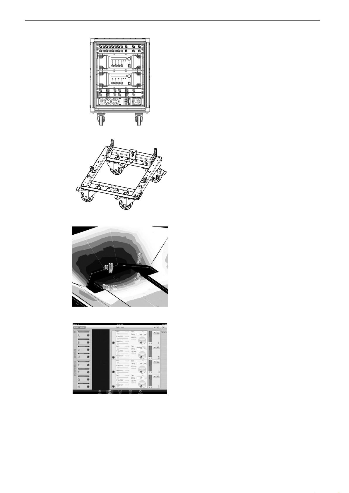
The NEXO Universal Amp Rack feeds 12
STM modules in any combination in groups
of 3. Comprising two NXAMP4x4 amplifiers,
2 digital input patches (DMU), 2 digital
output patches (DPU) and EtherSoundTM,
DanteTM or AES cards, the NUAR forms a
compact, powerful and scalable
amplification solution for STM systems of
any size.
STM Accessory Range. a full range of
accessories that provides safe, flexible and
simple means of transporting, protecting,
installing STM modules in touring
applications.
NS-1 simulation software assists in the
design and implementation of STM
modules. Please consult the NEXO web site
(www.NEXO.fr or www.NEXO-sa.com) for
the latest software releases.
NeMo Remote Monitoring: available for
iPad and Mac, NEXO’s NeMo Remote
Monitoring app provides remote control
over a NXAMP network from anywhere in
the venue.
Please devote your time and attention to reading this manual.
A comprehensive understanding of STM technologies, applications and specific features will help you
to operate your system at its full potential.
Page 9

STM CONNECTORS AND CABLING Page 9/62
2 STM CONNECTORS AND CABLING
2.1 Speaker modules connection
Connection system has been designed so that it is simple and mistake proof. STM modules connector panels
feature robust chassis metal connectors Speakon NL4 and/or NL8.
A wiring diagram is printed on the connection panel located on the back of each cabinet.
Table below gives STM general wiring assignment.
Module – Channel
NL4 / NL8 wiring
S118 - VLF
1-/1+
B112 - LF
2-/2+
M46 - MF
3-/3+
M46 - HF
4-/4+
M28 – LF/MF
1-/1+ (NL4 only)
M28 - HF
2-/2+ (NL4 only)
STM S118 connector panel
Speakon
Connecting
1(-)
S118 (-)
1(+)
S118 (+)
2(-)
To B112 (-)
2(+)
To B112 (+)
STM S118 is connected with Speakon
NL4FC plugs (not supplied). The 4 pins of the
2 Speakon sockets identified in / out are
connected in parallel within the enclosure.
Either connector can be used to connect
amplifier or to link to an additional S118 Sub
Module or to a B112 Bass Module. Therefore,
a single 4-conductor cable can connect two
amplifier channels up to 3xS118s and
3xB112s.
S118
WARNING
Operate only with NEXOTD Controller.
PROFESSIONALEQUIPMENT!
Please refer t o UserManual for
WorkingLoad Limits(WLL)
andRiggingInstructions.
WARNING
Disregard of RiggingInstructions
and/orWLL maydamage equipment
andri skpersonal injury or death.
WARNING
Exposure to high soundpressurel evels
maycausea permanent hearingloss.
Referto User Manual.
1 SUB
2 L F
MADE IN FRANCE
1 SUB
2 L F
Page 10

Page 10/62 STM CONNECTORS AND CABLING
STM B112 connector panel
Speakon
Connecting
1(-)
To S118 (-)
1(+)
To S118 (+)
2(-)
B112 (-)
2(+)
B112 (+)
STM B112 is connected with Speakon
NL4FC plugs (not supplied). The 4 pins of the
2 Speakon sockets identified in / out are
connected in parallel within the enclosure.
Either connector can be used to connect
amplifier or to link to an additional B112 Bass
Module or to a S118 Sub Module. Therefore,
a single 4-conductor cable can connect two
amplifier channels to up to 3xS118s and
3xB112s.
STM M46 connector panel
Speakon
Connecting
1(-)
To S118 (-)
1(+)
To S118 (+)
2(-)
To B112 (-)
2(+)
To B112 (+)
3(-)
M46 – MF (-)
3(+)
M46 – MF (+)
4(-)
M46 – HF (-)
4(+)
M46 – HF (+)
STM M46 is connected with Speakon NL8FC
plugs (not supplied). The 8 pins of the 2
Speakon sockets identified in / out are
connected in parallel within the enclosure.
Either connector can be used to connect
amplifier or to link to an additional M46 main
Module. Additionally, STM M46 panel
features 1 NL4 connector allowing local link
to S118 or B112.
Therefore, a single 8-conductor cable can
connect 4 amplifier channels to up to
3xS118s, 3xB112s and 3 M46s.
B112
WARNING
Operateonly wit h NEXOTD Controller.
PROFESSIONAL EQUIPMENT!
Please refer t oU serManual for
WorkingLoad Limits(WLL)
andRiggingInstructions.
WARNING
Disregardof RiggingInstructions
and/orWLLmay damageequipment
andrisk personalinjur y or death.
WARNING
Exposuret o highsound pressure levels
maycausea permanent hearingloss.
Referto User Manual.
1 SU B
2 L F
MADE IN FRANCE
1 SU B
2 L F
M46
1 SUB
2 L F
3 MF
4 H F
1 SUB
2 L F
3 MF
4 H F
WARNING
Operate only with NEXOTD Controller.
PROFESSIONALEQUIPMENT!
Pleaserefer t o UserManual for
WorkingLoad Limits (WLL)
andRiggingInstructions.
WARNING
Disregardof RiggingInstructions
and/orWLL maydamageequipment
andri skpersonali njury or death.
WARNING
Exposuret o high soundpressurelevels
maycausea permanent hearingl oss.
Referto User Manual.
1 SUB
2 L F
MADE IN FRANCE
Page 11
STM CONNECTORS AND CABLING Page 11/62
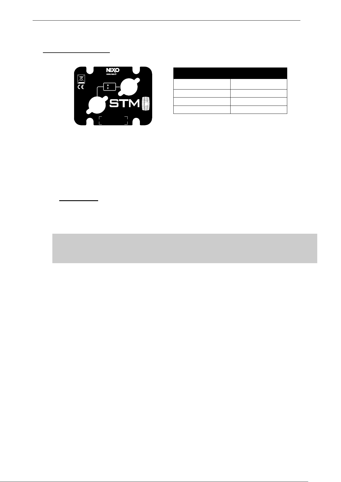
STM M28 connector panel
Speakon
Connecting
1(-)
M28 - LF (-)
1(+)
M28 - LF (+)
2(-)
M28 - HF (-)
2(+)
M28 - HF +)
STM M28 is connected with Speakon NL4FC
plugs (not supplied). The 4 pins of the 2
Speakon sockets identified in / out are
connected in parallel within the enclosure.
Either connector can be used to connect
amplifier or to link to an additional M28
Module.
2.2 STM cabling
STM cabling standard is 4x4mm2/AWG#10 (NL4) or 8x4mm2/AWG#10 (NL8).
Maximum cable run is 60 meters / 200 feet
IMPORTANT
Long speaker cables induce capacitive effects – up to hundreds of pF depending on the
quality of the cable - with a low-pass effect on high frequencies. If long speaker cables must
be used, ensure that they do not remain coiled while in use.
M28
SERIALNUMBER
MADE in FRANCE
1 LF
2 H F
Page 12

Page 12/62 STM AND NUAR NEXO UNIVERSAL RACK
3 STM AND NUAR NEXO UNIVERSAL RACK
The NEXO Universal Amp Rack (NUAR) provides NEXO users with a scalable, ‘plug & play’, amplified
audio distribution solution of unrivalled power and flexibility. Systems of any size can be configured
easily using channel by channel preset selection of any NEXO cabinet, and digital output patching.
The NUAR rack comprises a pair of NEXO NXAMP4X4 amplifiers, twin DMU digital input metering devices, a
pair of DPU digital output patching devices and a choice of 110V, 220V or dual-voltage mains distribution boxes
providing power to all the components in the rack.
System configuration is simple, using either ESMonitor the new NEXO NeMo iPad® app. NEXO cabinet presets
are selected on a channel by channel basis, with selected cabinet names displayed by the DPU for easy output
patching.
Digital input metering is provided by the DMU, clearly indicating the presence and status of input signals,
including network inputs.
An entirely new library of presets for every single cabinet in the NEXO range delivers linear phase across any
system, making it possible to mix and match NEXO cabinets.
Increased efficiency and versatility is inherent in NUAR’s mechanical design. The 14U chassis is suspended
within a robust rack case, featuring two sliding doors and an integrated rigging system. This enables up to 3
racks to be flown using an optional bumper and the easy attaching/detaching of a wheel board.
Each NUAR is fully configured and tested at NEXO to provide a truly versatile and tailored ‘Plug & Play’
amplification solution.
3.1 NUAR Components
For a complete description of these units, please refer to NEXO User Manuals.
3.1.1 NXAMP4x4
Among the most powerful amplifiers in the industry, the NXAMP4X4 integrates command, control,
amplification and protection functions within a relatively light weight and space-saving 4U rack.
By combining real-time monitoring of temperature, voltage and current with powerful dual-DSP control, the
NXAMP4X4 achieves exceptional performance with a high degree of protection for both amplifier and power
supply, while simultaneously offering all control parameters required for the speakers.
Page 13

STM AND NUAR NEXO UNIVERSAL RACK Page 13/62
The latest firmware load enables channel by channel preset selection for any speaker in the NEXO range. The
result of a 2-year development program, all presets have been revised using FIR filtering to ensure linear phase
across any combination of NEXO cabinets, making it possible to mix and match cabinets in a single, coherent
system.
EtherSound™ and Dante™ digital networking cards can be installed. Latest generation 24-bit audio converters
provide enhanced dynamic range with low latency (500us analogue input to output in ‘flat’ mode), eliminating
the need for external A/D conversion.
Improved power efficiency and decreased heat generation comes courtesy of four separate Switch Mode
Power Supplies, which ensure high power capacity with low load drive. NEXO amplification technology delivers
maximum efficiency in drive performance and power, while providing the audio quality of traditional class AB
amplifiers with the heat dissipation of class D amplifiers. This results in a 50% reduction in power consumption,
contributing to outstanding sound quality. Converters operate synchronized in the opposite phase, thus
cancelling noise.
The NXAMP4X4 delivers 4 x 4000W into 2 Ohm loads, and is available in 110V, 220V and dual voltage
versions.
3.1.2 DMU (Digital Metering Unit)
DMU is the ultimate tool for the easy monitoring of any activity on the NXAMP audio inputs. The DMU is totally
driven by the host NXAMP, with signal and power supply coming from the NXAMP’s GPIO port. Front panel
features include 4 analogue XLR inputs plus links, three RJ45 ports for digital audio networking and LED VU
meters. Particular care has been taken to ensure minimum insertion losses in the analogue audio signal.
Key Features:
• Intelligent input patch panel offering digital communication with NXAMPs.
• Provides input level meters on all analogue and network inputs.
• Fully passive design on the audio and network paths.
• Powered through the host NXAMP, no need for mains supply.
3.1.3 DPU (Digital Patching Unit)
The DPU is designed to optimise use of the NXAMP’s channel by channel preset selection by automatically
routing its outputs to any of 6 output connectors on the DPU front panel. Cabinet names and bridging status
are displayed alongside each output, making it easy to wire the system. Security is assured by fully redundant
power supplies and dual switching. When connecting DPU to the NXAMP, a routine first checks that the power
from the amplifier is coming from the correct channel. If communication is lost with the NXAMP, the DPU retains
its configuration until contact is resumed.
Key Features
• Intelligent input patch panel offering digital communication with NXAMPs.
• Provides input level meters on all analogue and network inputs.
• Fully passive design on the audio and network paths.
• Powered through the host NXAMP, no need for mains supply.
Page 14

Page 14/62 STM AND NUAR NEXO UNIVERSAL RACK
3.1.4 Digital audio networking
NUAR racks can be pre-configured with EtherSound™ or Dante™ digital audio networking capabilities,
enabling users to monitor and controlthe NXAMPs.
NXES104 EtherSoundTM Network Card
Key Features
• Extracts 4 audio streams (24 bits / 48 KHz) among the 2 x 64 channels of a ES100 EthersoundTM stream.
• IN and OUT port for simple daisy chain without any need for an external switch.
• 3rd Ethernet port for remote control of the whole network from any NXES104 card and ASIO streaming.
NXDT104 DanteTM Network Card
Key Features
• Receives 4 audio streams (24 bits / 48 KHz) in DanteTM format.
• Unique 3-port design can be used:
- Has an integrated 3 port gigabit switch
- Has two Dante™ redundant port plus an optional 3rd port for additional remote control
• Direct connection to PC using the ASIO format.
3.1.5 Power box
NUAR can be configured with a choice of 110V, 220V or dual-voltage power distribution boxes, allowing the
user to achieve the optimum balance of versatility and cost efficiency.
Where necessary, the power distribution boxes feature color-coding to assist power balancing when using three
phase supplies. The color-coding is also labelled on the rack case.
3.1.6 Rack
The 14U chassis is suspended within a rack case, featuring two sliding doors and an integrated rigging system.
Up to 3 racks can be flown using an optional bumper.
3.2 STM Setups
STM setups are available on NXAMP4x4 in “System Configuration” Menu in the STM section.
These setups are fixed in software and updated regularly: please consult the NEXO web site (www.nexo.fr) for
the latest software releases.
Load 4.0+ Key Features
Set up selection per channel
Linear phase on all set-ups
All NEXO systems compatible 20Hz-20kHz
Selectable crossover points for subs
8 fully parametric EQs per channel
3.2.1 NEXO STM configurations
These are NEXO recommended STM for proper STM operation. Please check STM setup list enclosed with
NXAMP loads (available at www.nexo-sa.com)
3.2.2 Custom STM configurations
NXAMP4x4 Load 4.0+ (“setup per channel”) allows re-configuring NEXO speaker setups in any combination
on the 4 channels when going into the Custom Setup menu.
Page 15

STM AND NUAR NEXO UNIVERSAL RACK Page 15/62
STM and NUAR configurations
A NUAR rack can feed 12 modules of STM – whatever they are – provided they are paralleled by 3.
Active Mode
3xSTM S118
2 channels of NXAMP4x4 in bridge stereo mode
3xSTM B112
2 channels of NXAMP4x4 in bridge stereo mode
3xSTM M46
2 channels of NXAMP4x4 in 4 channels mode
3xSTM M28
2 channels of NXAMP4x4 in 4 channels mode
IMPORTANT
- Paralleling less than 3 STM modules on NXAMP4x4 channels does not change power delivered
to each module
- Exceeding 3 paralleled STM modules on NXAMP4x4 channels will lead to a power drop of at
least 50% in each module.
12xS118 and 1 NUAR
Page 16

Page 16/62 STM AND NUAR NEXO UNIVERSAL RACK
12xB112 and 1 NUAR
12xM46 and 1 NUAR
Page 17

STM AND NUAR NEXO UNIVERSAL RACK Page 17/62
12xM28 and 1 NUAR
6xB112 and 6xM46
Page 18

Page 18/62 STM AND NUAR NEXO UNIVERSAL RACK
6xS118 and 6xB112
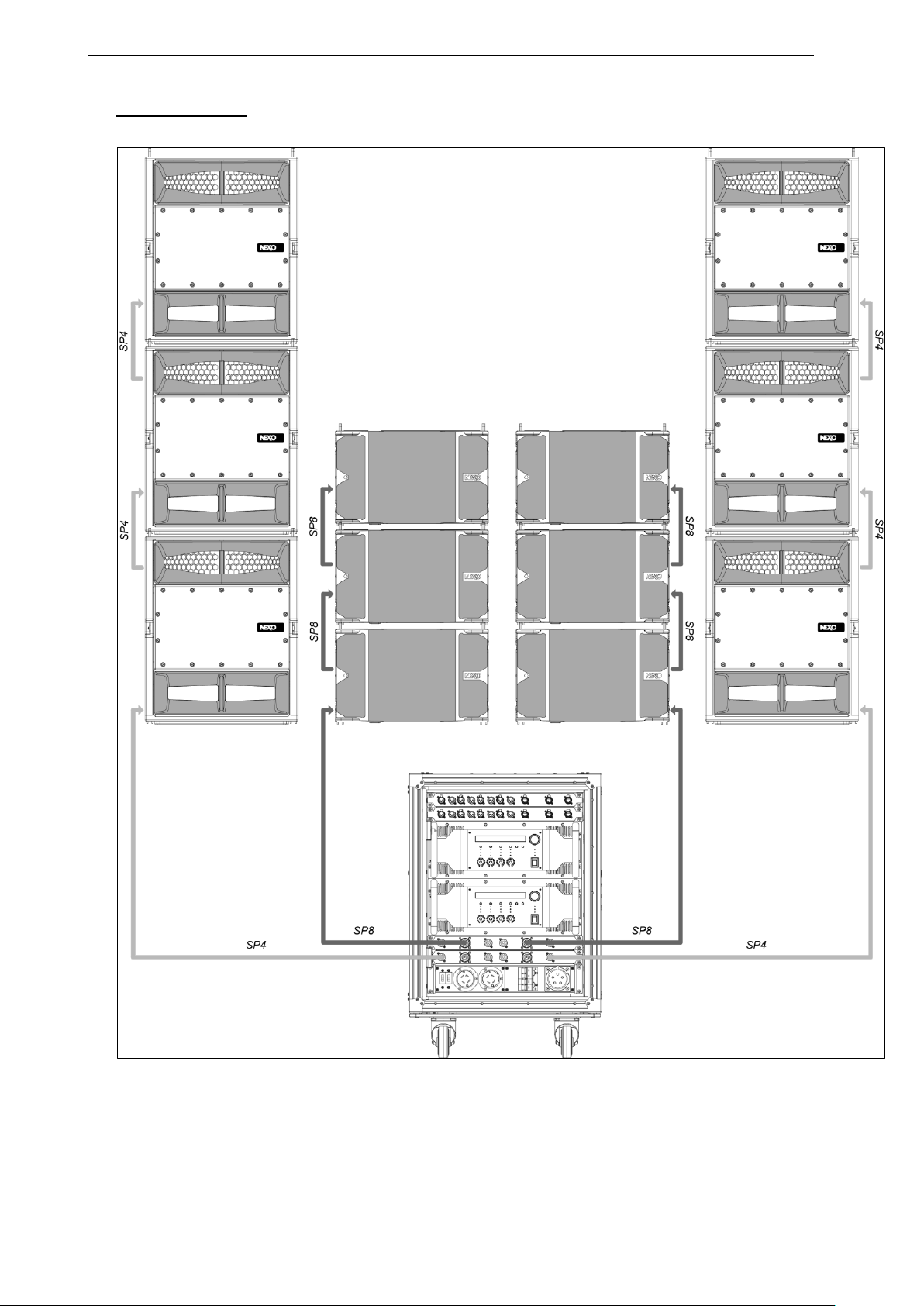
Page 19
STM AND NUAR NEXO UNIVERSAL RACK Page 19/62
6xS118 and 6xM46
Page 20
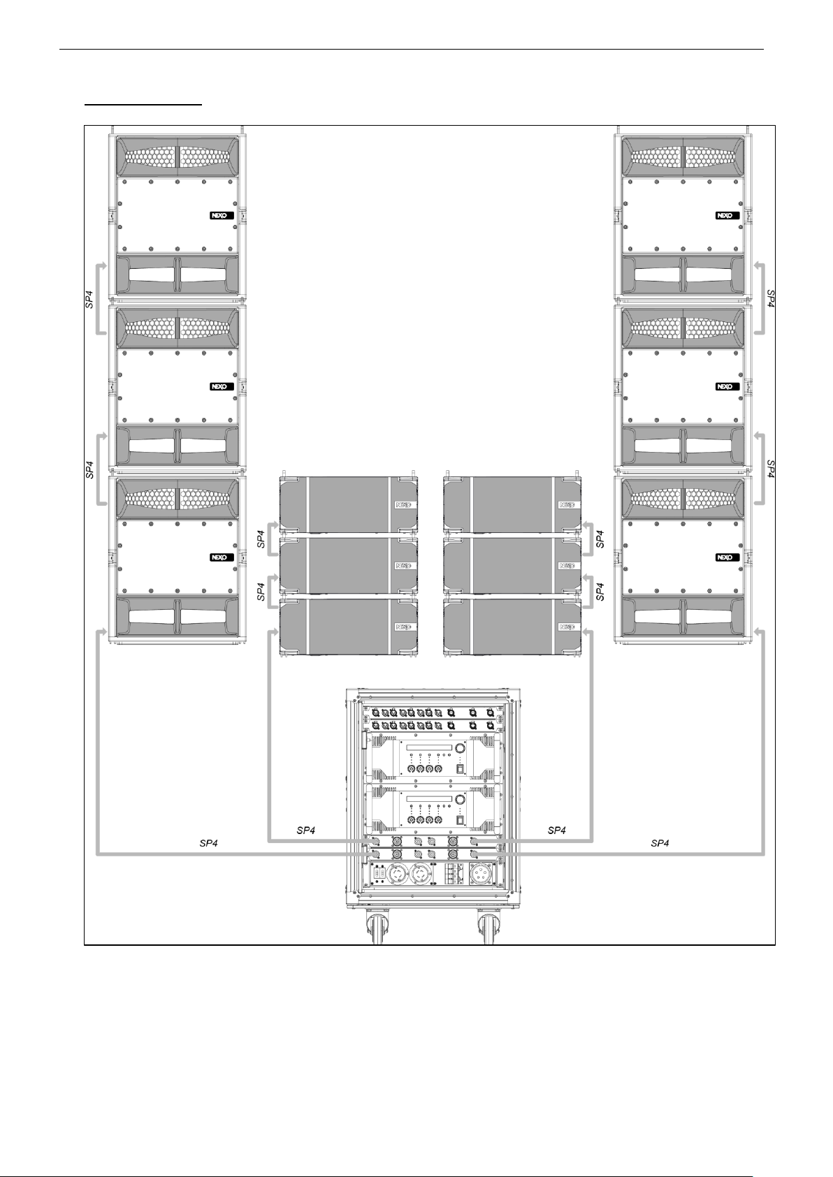
Page 20/62 STM AND NUAR NEXO UNIVERSAL RACK
6xS118 and 6xM28
Page 21
NS-1 SIMULATION SOFTWARE Page 21/62
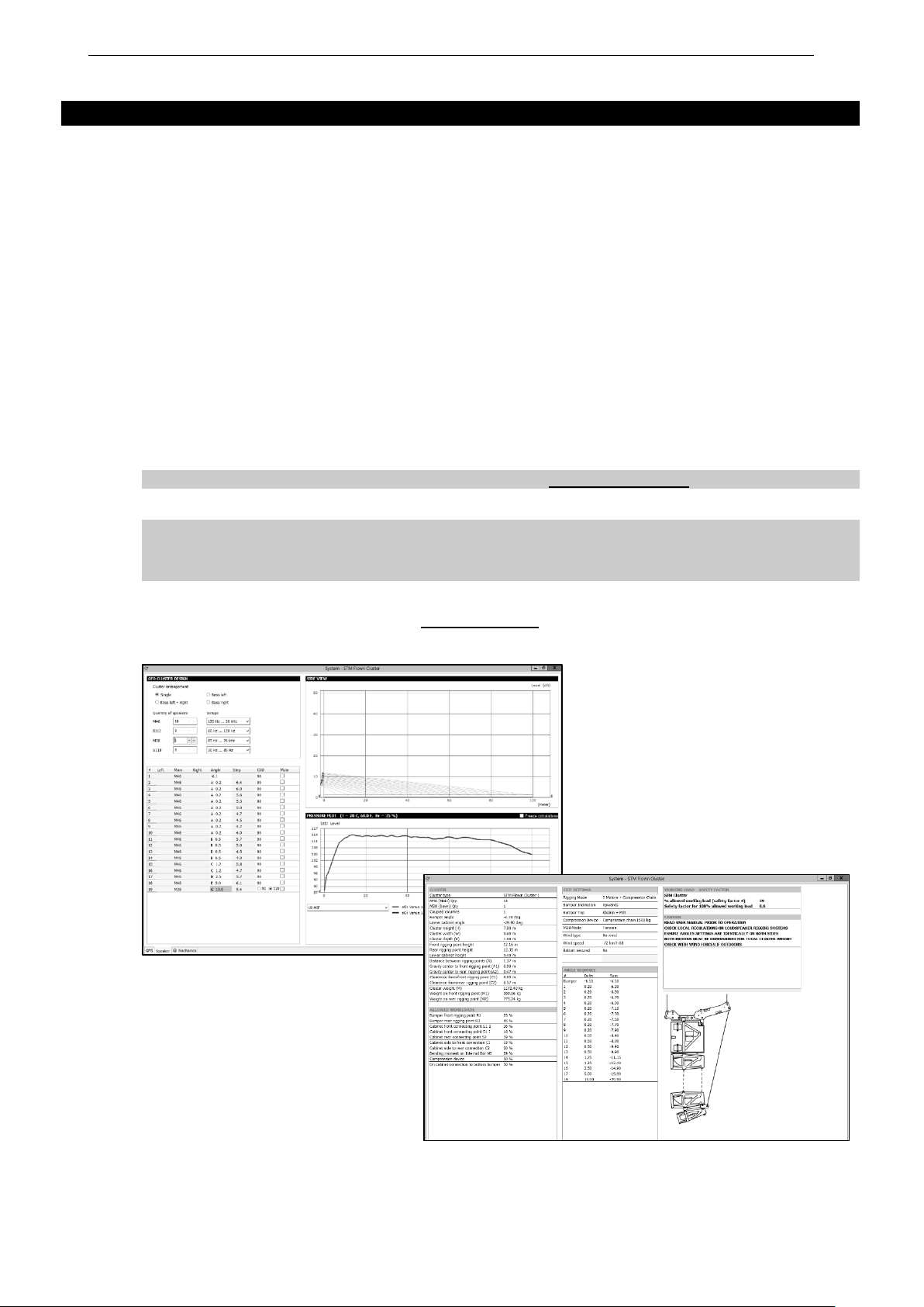
4 NS-1 SIMULATION SOFTWARE
NS-1 software is a R&D simulation tool derived application. It processes measured speaker data with complex
mathematical algorithms to assist the user in optimizing system design. Due to the complexity of the interaction
of multiple cabinets, it is simply not possible to reliably design curved vertical arrays without using the
processing power of a computer to predict the optimum array structure for a given audience geometry. The
design logic is far more complex than looking at a section drawing of the venue, measuring the overall angle
needed to cover the audience from the cluster location, and dividing by 10 degrees to determine the required
amount number of STM modules.
NS-1 is an easy to use tool that allows to shape the energy leaving the cluster to fit the audience. It predicts
pressure levels radiated from the system to ensure enough cabinets are provided for the application, as well
as mechanical constraints for safe flown systems.
In addition, it provides mechanical information for all clusters in agreement with Structural Analysis Reports
(available in the Help section): dimensions, weight, gravity center position, forces, moments, working load and
safety factor.
STM Structural Analysis Reports have been conducted by Vom Felde Gmbh, and is currently being submitted
to German Certification Organization RWTUV systems GmbH.
NS-1 installation package includes all NEXO User Manuals, Structural Analysis Reports and Certificates PDF
files.
NS-1 is a freeware available at www.nexo-sa.com
IMPORTANT
Never install a STM cluster without checking its acoustical performances and mechanical safety
in NS-1 prior to installation.
Any question or bug report please contact [email protected]
Page 22

Page 22/62 STM SYSTEM DEPLOYMENT PROCEDURE
5 STM SYSTEM DEPLOYMENT PROCEDURE
Before proceeding with assembly of STM arrays, please ensure that the components are present and
undamaged. A component list is appended to this manual. In the event of any shortage, please contact your
supplier.
For maximum efficiency the STM rigging system requires three experienced persons for set-up: typically one
motor hoist operator, and one STM operator per side of the array. Good synchronisation and crosscheck
between the operators are key elements for a reliable and safe set-up.
5.1 SAFETY FIRST
STM Rigging System structural computations and related documents are available in Geosoft2 or at Nexo
([email protected]) upon request.
We include this section to remind you of safe practice when flying the STM system. Please read it carefully.
However, user must always apply his or her knowledge, experience and common sense. If in any doubt, seek
advice from your supplier or NEXO agent.
This manual offers guidance only for STM loudspeaker systems. References in this manual to other rigging
equipment such as motor hoists, steels, shackles etc. are made to clarify the description of STM procedures.
The user must ensure that operators are properly trained by other agencies in the use of these items.
The STM Rigging System has been optimised for the deployment of curved vertical or horizontal tangent arrays
of STM loudspeakers. Angle adjustment between cabinets has been limited to specific settings to ensure
correct acoustic coupling.
The STM Rigging System is a professional precision tool set, and should be handled with extreme care. Only
persons who are fully conversant with the operation of the STM Rigging System and provided with suitable
safety equipment should deploy GEO Arrays. Misuse of the STM Rigging System could lead to dangerous
consequences.
Used and maintained correctly, the STM Rigging System will give many years of reliable service in portable
systems. Please take the time to read and understand this manual. Always use GEOSoft2 to determine the
optimum angle settings for a particular venue, hang point and curved vertical STM cluster. Applied forces and
moments are strongly cabinet quantity and angle configuration dependent. Cluster configuration must be
implemented and validated in Geosoft2 prior to installation.
5.1.1 Flown Systems Safety
Always inspect all the rigging components and cabinets for damage before assembly. Pay special attention to
the lifting points, and safety clips. If you suspect that any of the components are damaged or defective, DO
NOT USE THE AFFECTED PARTS. Contact your supplier for replacements.
Read this manual carefully. Also be familiar with the manuals and safe working procedures for any ancillary
equipment that will be used with the STM Rigging System.
Applied forces and moments are strongly cabinet quantity and angle configuration dependent. Cluster
configuration must be implemented and validated in Geosoft2 prior to installation.
Ensure that all local and National regulations regarding the safety and operation of flying equipment are
understood and adhered to. Information on these regulations can usually be obtained from Local Government
Offices.
When deploying a STM system always wear protective headwear, footwear and eye protection.
Do not allow inexperienced persons to handle a STM system. Installation personnel should be trained in
loudspeaker flying techniques and should be fully conversant with this manual.
Ensure that motor hoists, hoist control systems and ancillary rigging components are currently certified as safe
and that they pass a visual inspection prior to use.
Ensure that public and personnel are not allowed to pass beneath the system during the installation process.
The work area should be isolated from public access.
Never leave the system unattended during the installation process.
Do not place any object, no matter how small or light, on top of the system during the installation procedure.
The object may fall when the system is flown and is likely to cause injury.
Page 23

STM SYSTEM DEPLOYMENT PROCEDURE Page 23/62
Secondary safety steels must be installed once the system has been flown to the operating height. Secondary
steels must be fitted irrespective of requirements of the local safety standards applicable to the territory.
Ensure that the system is secure and prevented from pivoting around the motor hoist.
Avoid any form of excessive dynamic loading to the assembly (structural computations on STM Rigging System
are based on a 1/1.2 factor for hoist or motor acceleration).
NEVER attach any item to the STM system other than the STM accessories.
When flying outdoor systems, ensure that the system is not exposed to excessive wind or snow loads and is
protected from rainfall.
If wind velocity reaches or exceeds Beaufort 7 (60 km/h – 38 mp/h), the system must be landed.
The STM Rigging System requires regular inspection and testing by a competent test centre. NEXO
recommend that the system is load tested and certified annually or more frequently if local regulations require.
When de-rigging the system ensure that the same duty of care is given to the procedure as for the installation.
Pack STM components carefully to prevent damage in transit.
5.1.2 Ground Stacking Safety
Statistically, many more injuries occur due to unstable ground stacked PA systems than those associated with
flown systems. There are several reasons for this fact, however the message is clear:
Always survey the supporting structure upon which a ground stack is to be built. Always look beneath PA wings
to inspect the deck support and if necessary ask for the stage scrims and dressings be removed to allow
access.
If the stage surface slopes, as it does in some theatres, ensure that the system is prevented from sliding
forwards due to vibration. This may require the fitting of timber battens to the stage floor.
For outdoor systems ensure that that the system is protected from wind forces which might cause the ground
stack to become unstable. Wind forces can be huge, especially upon large systems, and should never be
underestimated. Observe meteorological forecasts, calculate the “worst case” effect upon the system prior to
erection and ensure that the system is secured appropriately.
Take care when stacking cabinets. Always employ safe lifting procedures and never attempt to build stacks
without sufficient personnel and equipment.
Never allow anyone, whether operators, artists or members of the public to climb onto a ground stacked PA
system. Anyone who needs to climb over 2m (6 ft) high should be fitted with suitable safely equipment including
a clip-on harness. Please refer to local Health and Safety legislation in your territory. Your dealer can help with
advice on access to this information.
Apply the same attention to all safety matters when de-stacking systems.
Be aware that safety procedures are as important in the truck and in the warehouse as they are at the venue.
5.1.3 Contacts
Correct training is fundamental to safe practise when working with loudspeakers flying systems. NEXO
recommend that users contact local industry associations for information on specialist course.
Information for International training agencies can be obtained by contacting either:
The Production Services Association (PSA),
School Passage,
Kingston-upon-Thames,
KT1 SDU Surrey,
ENGLAND
Telephone: +44 (0) 181 392 0180
ESTA
Entertainment Services & Technology Association
875 Sixth Avenue, Suite 1005
NEW YORK, NY 10001 USA
Phone: 212-244-1505 – Fax: 212-244-1502
[email protected] - www.esta.org
Page 24
Page 24/62 STM SYSTEM DEPLOYMENT PROCEDURE
5.2 General Description
5.2.1 STM Modules
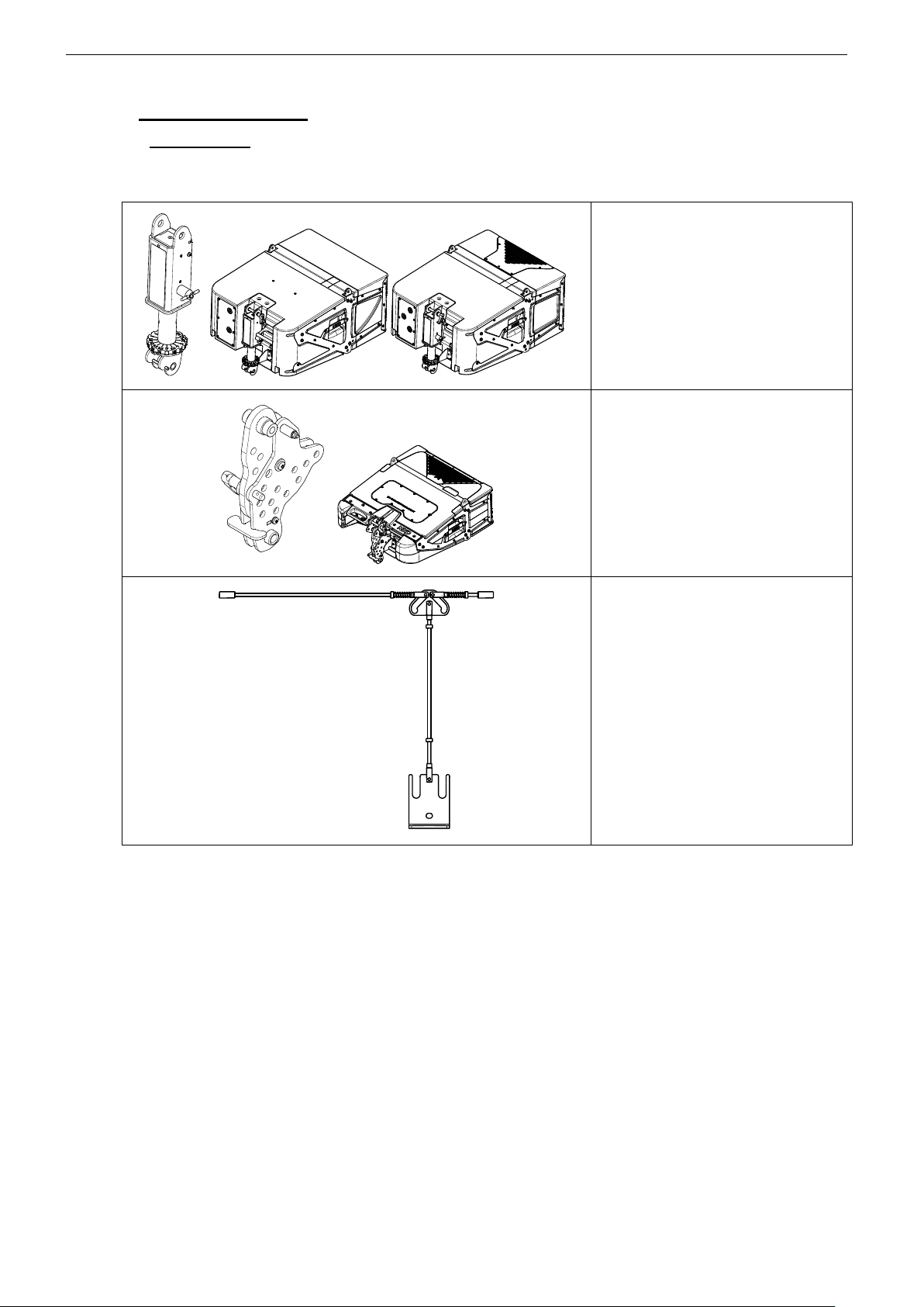
STM SYSTEMS SHARE IN COMMON AN INNOVATIVE PATENTED RIGGING SYSTEM, WHERE ALL ASSEMBLY OPERATIONS ARE DONE FROM
THE BACK OF THE MODULES:
PistonRigTM allows pre-setting of intercabinet angle values on M46 and B112
modules, from 0.2° to 10°
CompassRig™ allows pre-setting of
inter-cabinet angle values between M28
modules, from 0.2° to 15°
REDLock™ handle locks front rigging
points from rear of cabinet
STM rigging hardware allows to fly or stack single column clusters, as well as double and triple column clusters.
Each cluster configuration is an assembly of upper and lower rigging parts attached to cabinets in 3 points:
2 in the front with spring pins fixed inside the bumper,
1 in the back with a quick release pin.
The 2 and 3 columns wide configurations use coupling bars and beams.
The entire rigging of the STM is a combination of these different rigging parts.
The pages below describe every assembly of STM in flown configuration for single, double or triple column. The array
is always composed of the four modules (M46, B112, S118 and M28) for general description; users will adapt the type
and number of cabinets according to their project.
Page 25
STM SYSTEM DEPLOYMENT PROCEDURE Page 25/62
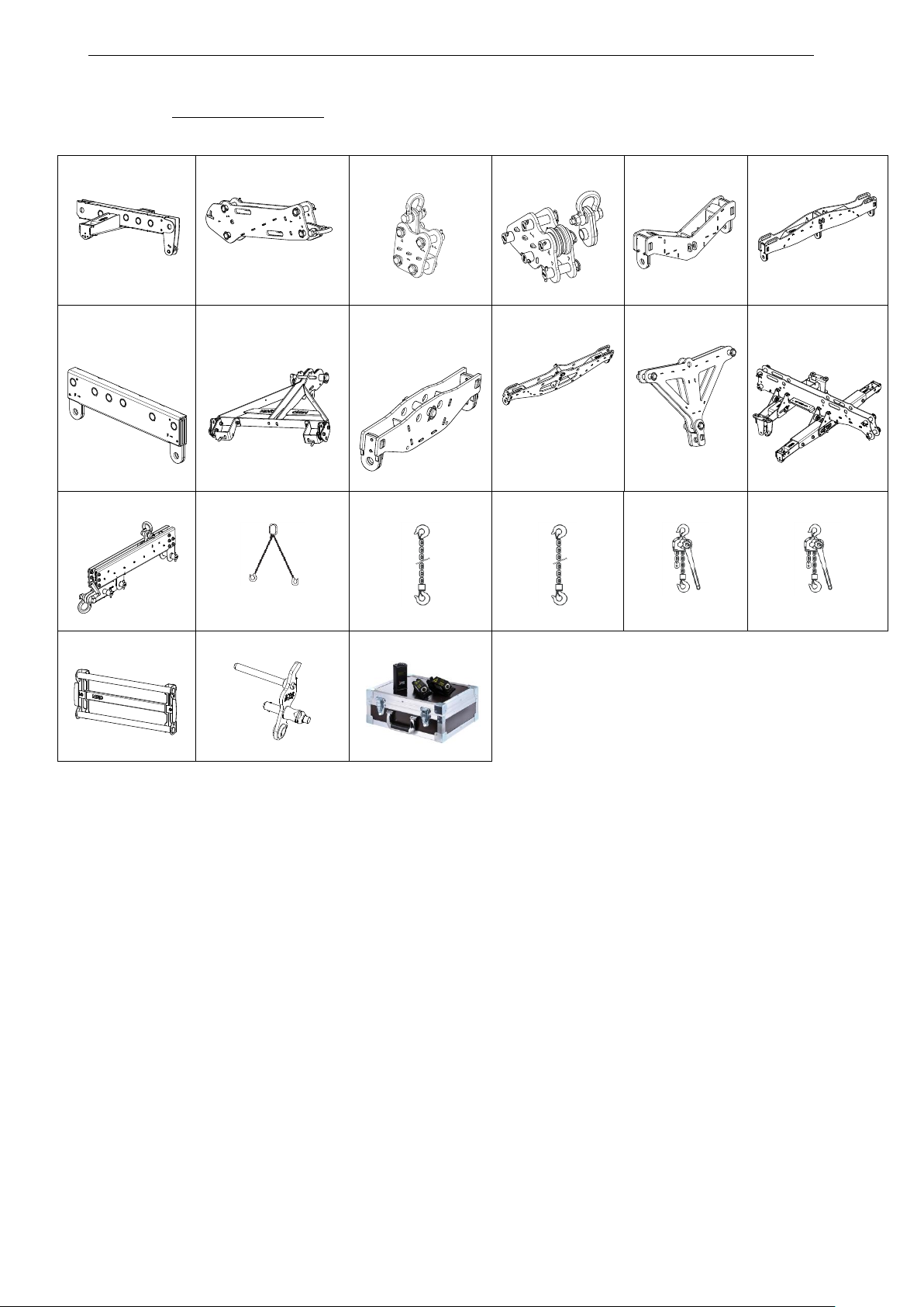
5.2.2 Rigging Components
STT-XBOW
STT-KBEAM
STT-MLINK
STT-PTILT
STT-XCOUP2
STT-XCOUP3
STT-MBEAM
STT-BTBUMPER
STT-BCOUP2
STT-BCOUP3
STT-DPLATE
STT-LBUMPER
STT-VBUMP
VXT-BRIDLE23
GTT-BCCH
STT-BCCH3
VXT-LEVA750
VXT-LEVA1500
STT- FHANDLE
STT-M46TOM28
VXT-LIKM
Page 26
Page 26/62 STM SYSTEM DEPLOYMENT PROCEDURE
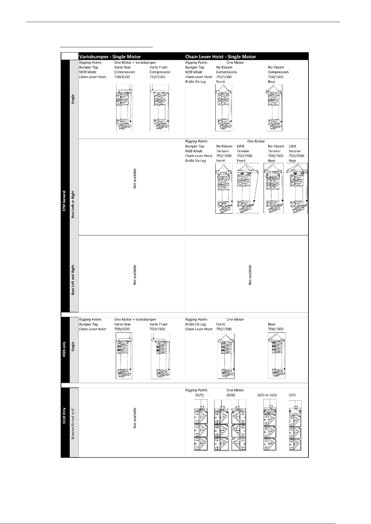
5.2.3 One rigging point rigging modes
Page 27
STM SYSTEM DEPLOYMENT PROCEDURE Page 27/62
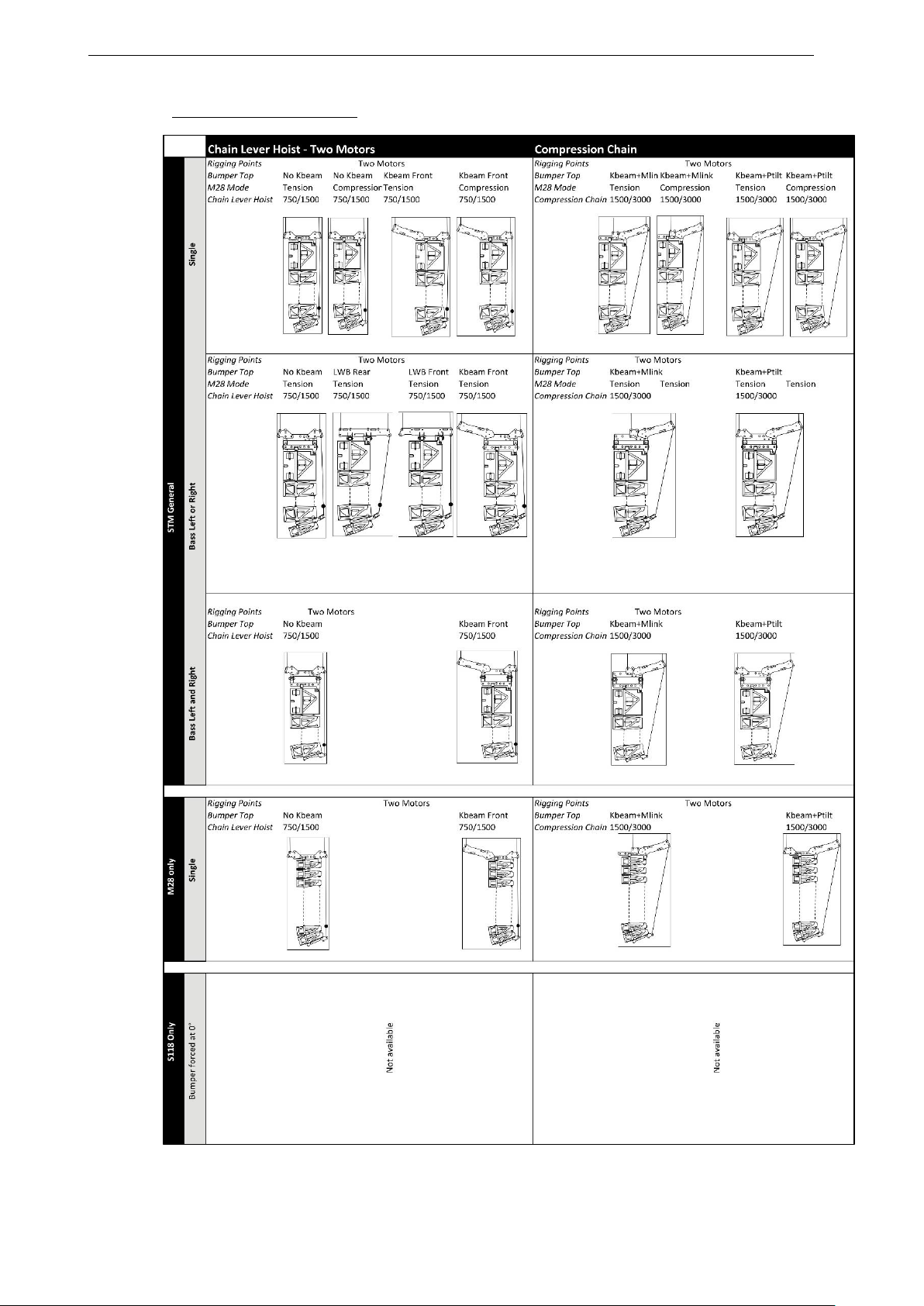
5.2.4 Two rigging points modes
Page 28
Page 28/62 STM SYSTEM DEPLOYMENT PROCEDURE
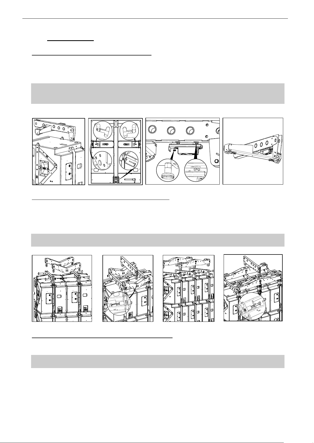
5.3 Upper assembly
Connecting XBOW to the top of the first cabinet(s)
o Insert the XBOW into the 3 fixing points: 2 on the sides and one at the back of the STM module
o Lock the lateral spring pins located inside the XBOW to the front lateral holes of the STM module
o Insert quick release pin at the back, in the hole located at the top of the corresponding piston
IMPORTANT
Ensure XBOW springs are functional
Ensure-XBOW lateral spring pins and rear quick release pin are properly locked into top cabinet
o Insert VXT-LIKM Laser inclinometer below XBOW and connect 3 pin XLR cable to it
Connecting XBOW to XCOUP2 (XCOUP3) coupling beams
o Insert front coupling beam XCOUP2 (XCOUP3) into left and right XBOWs, then lock these 2 components by
inserting the steel pins into the corresponding holes
o Insert safety pins into steel pins hole and lock safety pin by rotating its ring around steel pin
o Repeat the same procedure for the rear coupling XCOUP2 (XCOUP3)
IMPORTANT
Ensure assembly is properly locked on these 4 (6) points
Connecting MBEAM to XCOUP2 (XCOUP3) coupling beams
o Insert the MBEAM fixing points into XCOUP2 (XCOUP3) coupling beams then release XCOUP2 (XCOUP3)
spring pins so that above components are locked
IMPORTANT
Ensure-XCOUP2 (XCOUP3) spring pins are properly locked into MBEAM
Page 29
STM SYSTEM DEPLOYMENT PROCEDURE Page 29/62
5.4 Flying on a single motor with bridle
Single motor with bridle mode is only available for single or double columns clusters
S118 are not allowed in combination with other STM modules in this mode
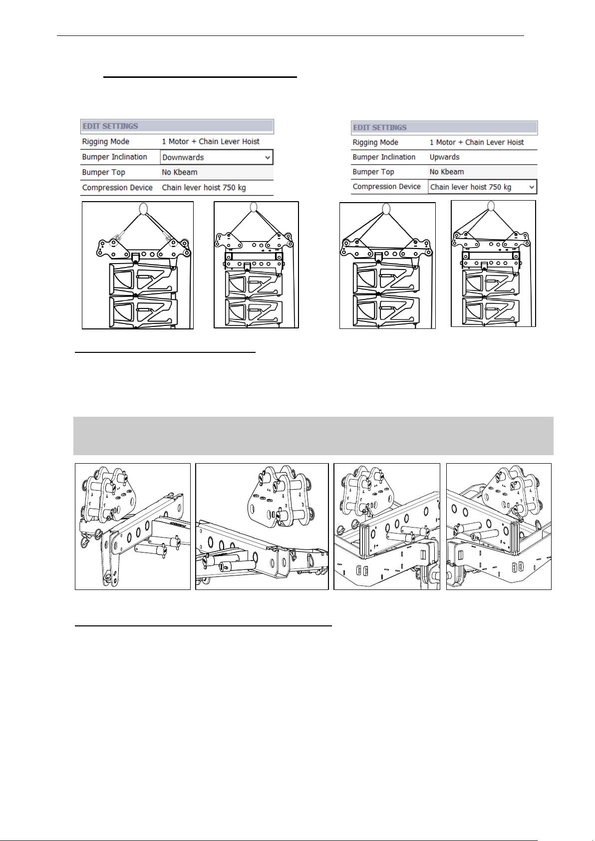
Connecting PTILTs to XBOW or MBEAM
o Position first PTILT to the front of XBOW or MBEAM then lock these components by inserting steel pins into
the corresponding holes
o Insert safety pins into steel pins holes and lock safety pin by rotating its ring around steel pin
o Position second PTILT to the rear of XBOW or MBEAM then repeat the same safety procedure than above
IMPORTANT
Ensure safety pins springs are functional
Ensure PTILT is properly locked to XBOW or MBEAM
Connecting PTILTs to XBOW Connecting PTILTs to MBEAM
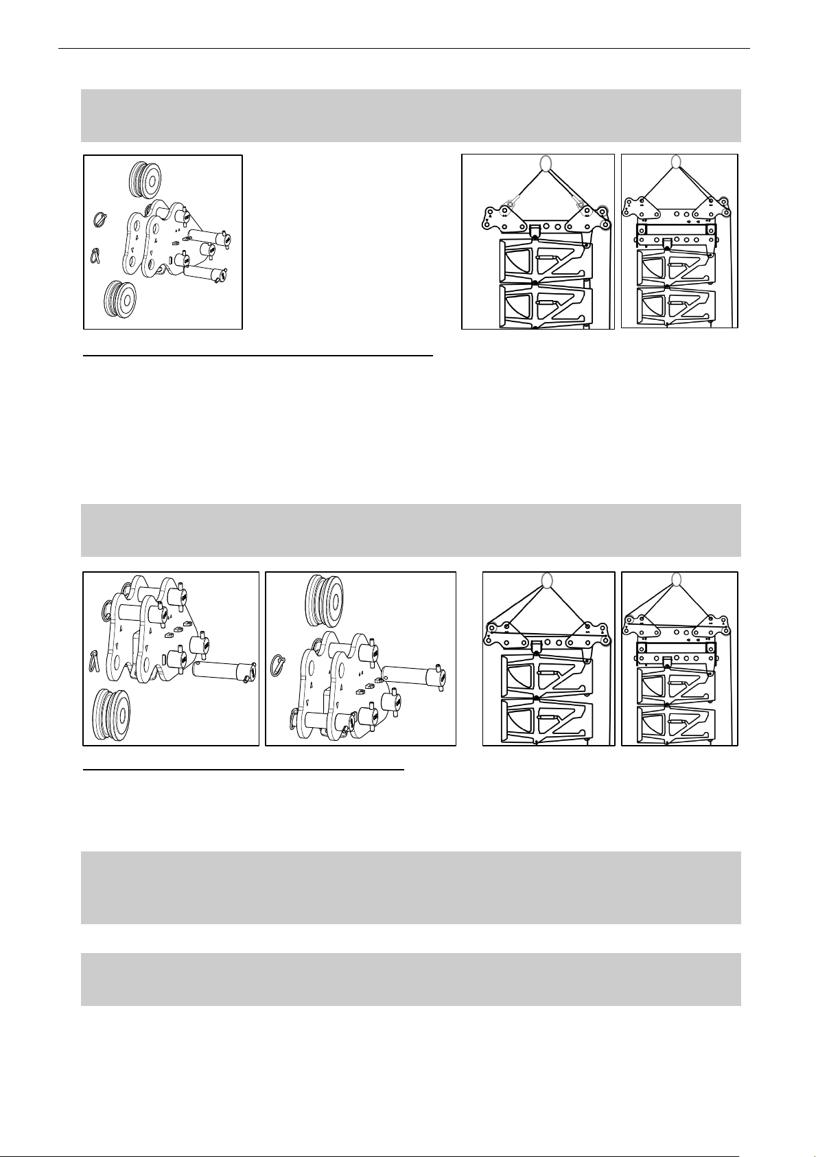
Positioning REA wheels to PTILT for bumper negative tilt
o Position lower REA wheel to the rear PTILT (rig point ) then lock these 2 components by inserting steel pins
into the corresponding holes
o Insert safety pins into steel pins holes and lock safety pin by rotating its ring around steel pin
o Position lever hoist chain above lower REA wheel so that it follows the path as in below drawings
o Position upper REA wheel to the rear PTILT (rig point ∆) then lock these 2 components by inserting steel pins
into the corresponding holes
o Insert safety pins into steel pins holes and lock safety pin by rotating its ring around steel pin
Page 30
Page 30/62 STM SYSTEM DEPLOYMENT PROCEDURE
IMPORTANT
Ensure safety pins springs are functional
Ensure REA is properly locked to PTILT
Positioning REA wheels to PTILT for bumper positive tilt
o Position lower REA wheel to the rear PTILT (rig point ) then lock these 2 components by inserting steel pins
into the corresponding holes
o Insert safety pins into steel pins holes and lock safety pin by rotating its ring around steel pin
o Position lever hoist chain above lower REA wheel so that it follows the path as in below drawings
o Position upper REA wheel to the front PTILT (rig point ∆) then lock these 2 components by inserting steel pins
into the corresponding holes
o Insert safety pins into steel pins holes and lock safety pin by rotating its ring around steel pin
IMPORTANT
Ensure safety pins springs are functional
Ensure REA is properly locked to PTILT
Finalizing the setup of top bumper rigging elements
o Insert centring devices into front and rear PTILT rig points ∆∆, then lock these devices by inserting the steel
pin into the corresponding hole
o Connect the bridle ring to the motor hoist, one bridle leg to the front centring device and the other bridle leg to
the rear centring device
IMPORTANT
Motor Hoist must be rated for total cluster weight
Bridle must be rated for twice total cluster weight
Please refer to NS1 mechanical information
o Attach compression upper chain lever hoist hook to bridle ring
IMPORTANT
Compression chain lever hoist must be rated according to compression pullback force.
Please refer to NS1 mechanical information
Page 31
STM SYSTEM DEPLOYMENT PROCEDURE Page 31/62
o If top modules are on a dolly, unlock the dolly by pulling bottom cabinet RedLock handle
o Lift assembly slightly off the ground (and store dolly)
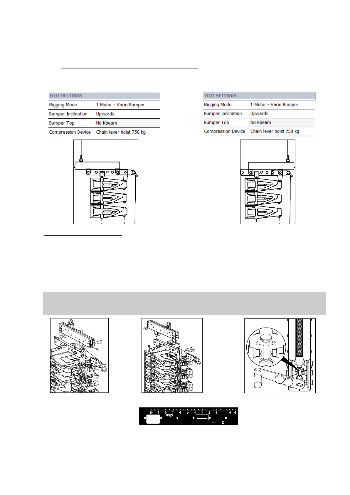
5.5 Flying on a single motor with Variobumper
Single motor with Variobumper mode is only available for single column clusters
S118 are not allowed in combination with other STM modules in this mode
Connecting VBUMP to XBOW
o Position VBUMP main beam on top of XBOW and insert VBUMP tail beam into X-BOW as in drawings below
for positive or negative bumper tilt
o Lock these 3 components by inserting steel pins into the corresponding holes
o Insert safety pins into steel pins holes and lock safety pin by rotating its ring around steel pin.
o Position and lock the crank as in drawings below
o Adjust VBUMP main beam shackle position according to NS1 “Rigging Point Position” value
IMPORTANT
Ensure safety pins springs are functiona
Ensure VBUMP main beam and tail beam are properly locked to XBOW
Connecting VBUMP to XBOW for negative tilt Connecting VBUMP to XBOW for positive tilt Locking the crank
Adjusting VBUMP rigging point position
UPTILT
2MOTORS
DOWNTILT
2MOTORS
UPTILT
1MOTOR
DOWNTILT
1MOTOR
LIFTINGCHAIN
SERIALNUMBER
STT-LBUMPER
MADEIN FRANCE
www.nexo.fr
0
www.nexo-sa.com
STT-VBUMP
MADEINFRANCE
PROFESSIONALEQUIPMENT
PleaserefertoUserManualforWorking
LoadLimits(WLL)andRigginginstructions.
WARNING
DisregardingRiggingInstructionsand/orWWLmay
damageequipmentandriskpersonalinjuryordeath.
Weight: 25kg/55 lb
Page 32
Page 32/62 STM SYSTEM DEPLOYMENT PROCEDURE
Finalizing the setup of top bumper rigging elements
o Connect the motor hoist to the VBUMP main beam shackle
IMPORTANT
Motor Hoist must be rated for total cluster weight
Please refer to NS1 mechanical information
o Connect the chain lever hoist hook to the VBUMP tail beam shackle
IMPORTANT
Compression chain lever hoist must be rated according to compression pullback force
Please refer to NS1 mechanical information
o Lift bumper assembly off the ground so that first cabinet dolly can roll underneath
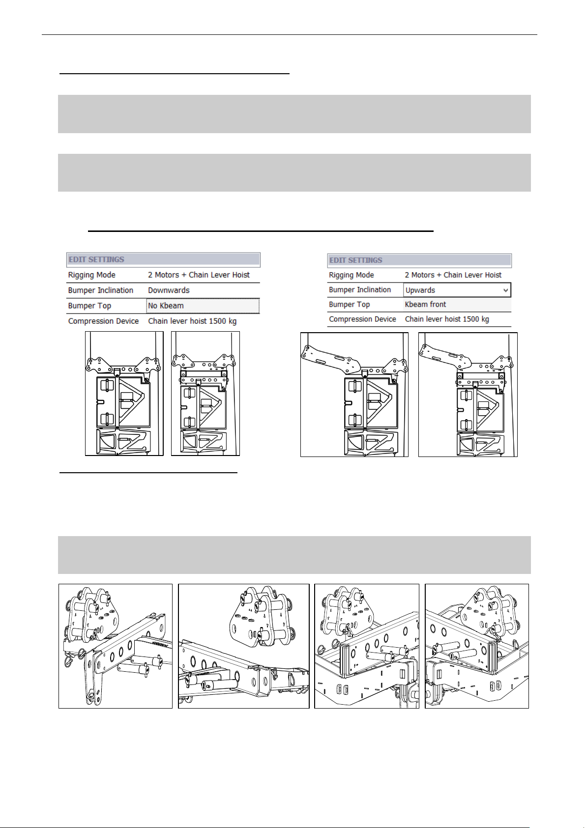
5.6 Flying on two motors and a chain lever hoist (M28 default mode)
This flying mode should be considered as the default rigging mode to be applied when flying STM M28.
Connecting PTILTs to XBOW or MBEAM
o Position first PTILT to the front of XBOW or MBEAM then lock these components by inserting steel pins into
the corresponding holes
o Insert safety pins into steel pins holes and lock safety pin by rotating its ring around steel pin
o Position second PTILT to the rear of XBOW or MBEAM then repeat the same safety procedure than above
IMPORTANT
Ensure safety pins springs are functional
Ensure PTILT is properly locked to XBOW or MBEAM
Connecting PTILTs to XBOW Connecting PTILTs to MBEAM
Page 33
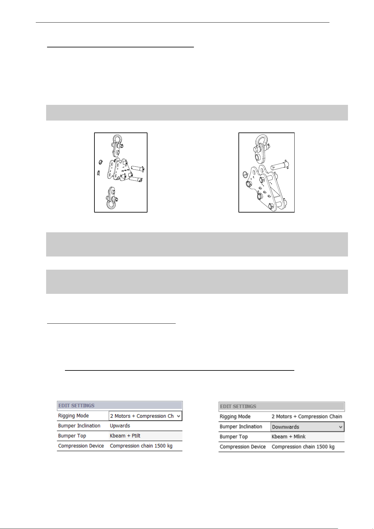
STM SYSTEM DEPLOYMENT PROCEDURE Page 33/62
Finalizing the setup of top bumper rigging elements
o Insert centring device into front PTILT main rig point ∆ (1 unit), then lock these 2 components by inserting the
steel pin into the corresponding hole
o Insert safety pins into steel pin hole and lock safety pin by rotating its ring around steel pin
o Insert centring devices into rear PTILT upper main rig point ∆ (1 unit) and into PTILT lower compression point
(1 unit), then lock these 3 components by inserting the steel pins into the corresponding holes
o Insert safety pins into steel pin holes and lock safety pins by rotating its rings around steel pins
IMPORTANT
Ensure safety pins springs are functional
o Attach motor hoists to front and rear PTILT upper centring devices
Attaching centring devices to rear PTILT Attaching centring device to front PTILT
IMPORTANT
Both motor hoists must be rated for total cluster weight
Please refer to NS1 mechanical information
o Attach compression upper chain lever hoist hook to PTILT lower centring device
IMPORTANT
Compression chain lever hoist must be rated according to compression pullback force
Please refer to NS1 mechanical information
o If top modules are on a dolly, unlock the dolly by pulling bottom cabinet RedLock handle
o Lift assembly slightly off the ground (and store dolly)
Alternative mode for important bumper up tilt
When important bumper positive angle is required (such as delay towers in stadium concerts), front PTILT can
be replaced by KBEAM in order to move front rigging point frontwards
o Proceed as above, except that KBEAM replaces front PTILT and must be connected to XBOW or MBEAM
through its articulation point
5.7 Flying on two motors and kelping chain (M46 + B112 default mode)
This flying mode should be considered as the default rigging mode to be applied when flying STM B112 and
STM M46
Page 34
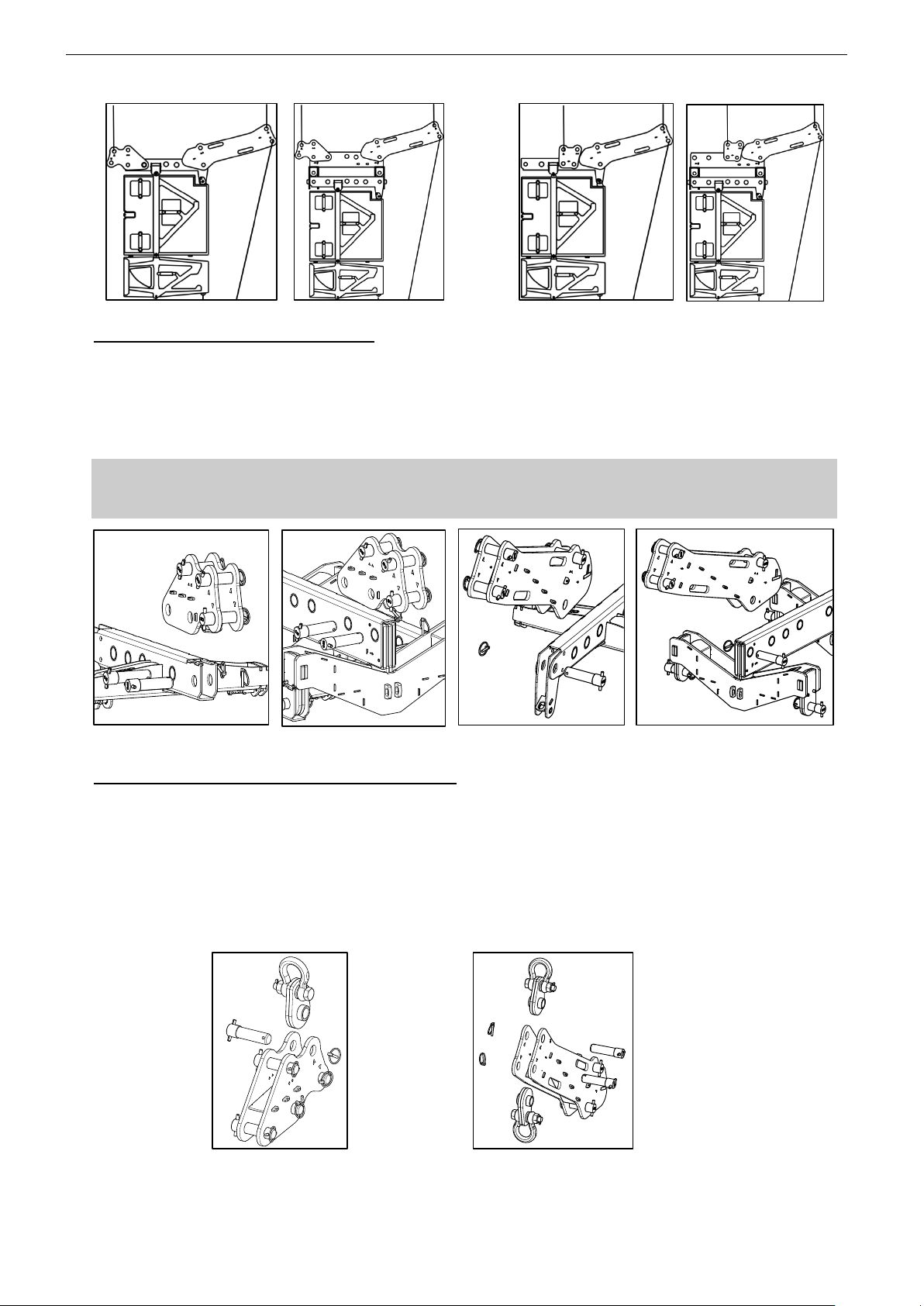
Page 34/62 STM SYSTEM DEPLOYMENT PROCEDURE
Connecting PTILTs to XBOW or MBEAM
o Position first PTILT to the front of XBOW or MBEAM then lock these components by inserting steel pins into
the corresponding hole
o Insert the KBEAM into the rear end of MBEAM then lock these 2 components by inserting steel pin into the
hole as displayed in side drawing
o Insert safety pin into steel pins hole and lock safety pin by rotating its ring around steel pin
IMPORTANT
Ensure safety pins springs are functional;
Ensure KBEAM is properly locked to MBEAM, and can be articulated around its axis
Connecting front PTILT to XBOW or MBEAM Connecting rear KBEAM to XBOW or MBEAM
Finalizing the setup of top bumper rigging elements
o Insert centring device into PTILT main rig point ∆ (1 unit), then lock these 2 components by inserting the steel
pin into the corresponding hole
o Insert safety pins into steel pin hole and lock safety pin by rotating its ring around steel pin
o Insert centring devices into KBEAM upper main rig point ∆ (1 unit) and into KBEAM lower compression point
(1 unit) , then lock these 3 components by inserting the steel pins into the corresponding holes
o Insert safety pins into steel pin holes and lock safety pins by rotating its rings around steel pins
o Attach motor hoists to PTILT and KBEAM upper centring devices
Page 35
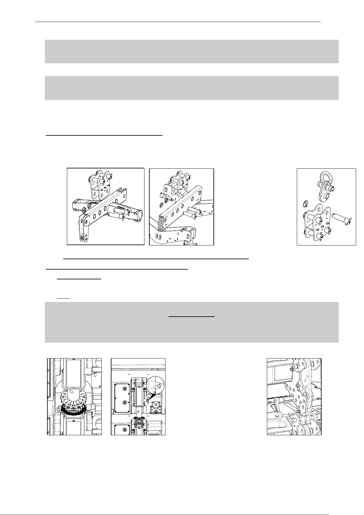
STM SYSTEM DEPLOYMENT PROCEDURE Page 35/62
IMPORTANT
Both motor hoists must be rated for total cluster weight.
Please refer to NS1 mechanical information
o Attach compression upper chain hook to KBEAM lower centring device
IMPORTANT
Compression chain must be rated according to compression pullback force.
Please refer to NS1 mechanical information
o If top modules are on a dolly, unlock the dolly by pulling bottom cabinet RedLock handle
o Lift assembly slightly off the ground (and store dolly)
Alternative mode to fly from gravity center
In order to avoid front swinging of the system when compression force is applied (see section XX), it is possible
to fly STM cluster from its gravity center position by using MLINK instead of PTILT
o Proceed as above, except that MLINK replaces front PTILT and must be connected to XBOW or MBEAM
according to below drawings
5.8 Connecting subsequent modules and presetting angles
Upper speaker modules assembly angle pre-setting
o M46 and/or B112: Set speaker angles as specified from NS-1 Software by turning piston wheels
o Rotate piston lock handles from “STORAGE” (horizontal) to “OPERATION” position (vertical)
o M28: Set speaker angles as specified from NS-1 Software by inserting pin in CompassRig in appropriate hole
WARNING
M46 and/or B112
Ensure lock handles are in “OPERATION” position
If not, pistons will be damaged at the time compression force is applied
Ensure that angle selection is identical on M46 and adjacent B112
o Connect speaker cables
Presetting angle on M46&B112 and moving to “operation” Presetting angle on M28 by inserting pin
Page 36
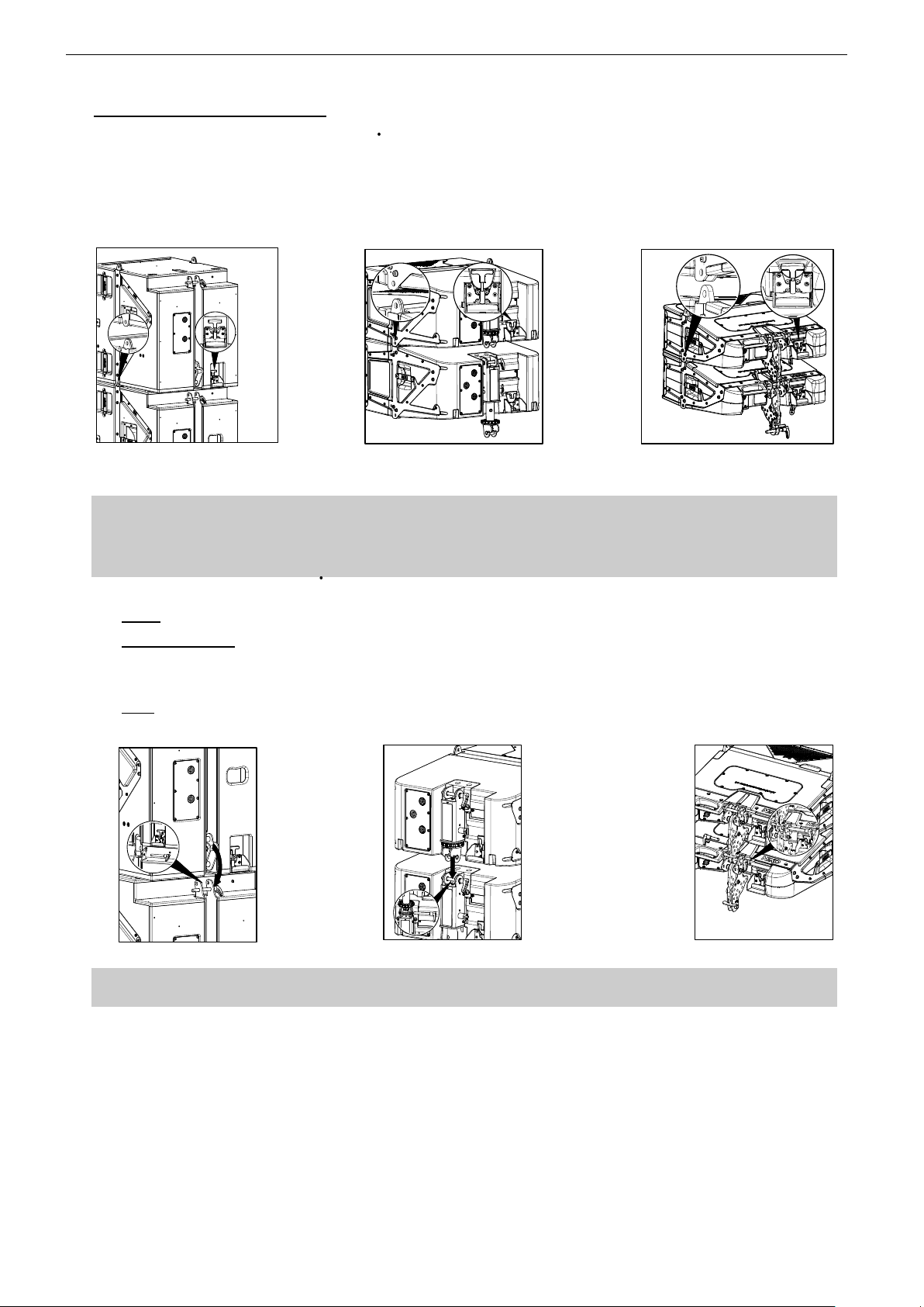
Page 36/62 STM SYSTEM DEPLOYMENT PROCEDURE
Connecting subsequent modules
o Lift upper assembly so that next module or dolly package can set underneath
o Align module or second dolly package below upper assembly
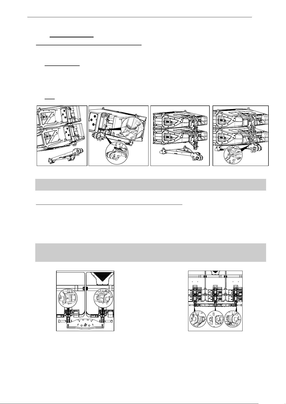
o Lower upper assembly into position, aligning side rigging slots on both sides of the cabinets
o Connect upper assembly to the second set of cabinets by pushing REDLOCK™ into “LOCK” position
o Ensure REDLOCK™ safety pins are locked into handle holes
Front locking on S118 Front locking on B112 and M46 Front locking on M28
IMPORTANT
Side locking pins must be flush to rigging plates on both sides of the cabinet
If locking pins appear to be going inwards in relation to rigging plates, cabinets must not be flown
Ensure all REDLOCK™ safety pins are locked into handle holes
o S118: insert rear quick release pin on the rear hinge so that upper set is connected to lower set
o M46 and/or B112: rotate lock handle of first set bottom cabinets in “OPERATION” mode (vertical position)
Slide upper set bottom modules piston axis and insert rear quick release pins so that upper set is connected
to lower set
o M28: extend upper set bottom modules CompassRig™ and insert rear quick release pins so that upper set is
connected to lower set
Rear locking on S118 Rear locking on B112 and M46 Rear locking on M28
IMPORTANT
Check rear quick release pins are fully engaged and locked
o Unlock the dolly from the bottom cabinets by pulling REDLOCK™ handle, and store dolly
o Connect speaker cables
o Lift up the assembly
o Repeat the same procedures as before until the full array is off the ground
Page 37
STM SYSTEM DEPLOYMENT PROCEDURE Page 37/62
5.9 Lower Assembly
Connecting BTBUMPERs below bottom modules
o Align BTBUMPERs to bottom cabinet side rigging slots, and lock the BTBUMPERs to bottom cabinets by
pushing REDLOCK™
o M46 and/or B112: Slide bottom cabinets pistons to bottom bumper connection point by rotating lock handle of
the last cabinet in OPERATION mode (vertical position), and insert quick release pin.
o Turn bottom cabinet piston wheels to ■ parking position.
o Lift BTBUMPERs so that they are adjacent to bottom cabinets and lock them by turning piston lock handle to
“STORAGE” (horizontal position)
o M28: rotate CompassRig, and insert pin into “BTBUMP” hole
Connecting bottom bumper to B112 or M46 Connecting bottom bumper to M28
IMPORTANT
Check rear quick release pins are fully engaged and locked
Connecting BTBUMPER to BCOUP2 (XCOUP3) bottom coupling bar
o Insert bottom bumper coupler BCOUP2 (BCOUP3) into the 2 (3) fixing points located at the back of the
BTBUMPERs.
o Insert the steel pins into the corresponding holes
o Insert safety pins into steel pin hole and lock safety pin by rotating its ring around steel pin
o Check that all elements are properly locked
IMPORTANT
Ensure safety pins springs are functional
Ensure BCOUP2 (BCOUP3) is properly locked to BTBUMPERs, and can be articulated around its axis
Coupling 2xBTBumpers with BCOUP2 Coupling 3xBTBumpers with BCOUP3
Page 38
Page 38/62 STM SYSTEM DEPLOYMENT PROCEDURE
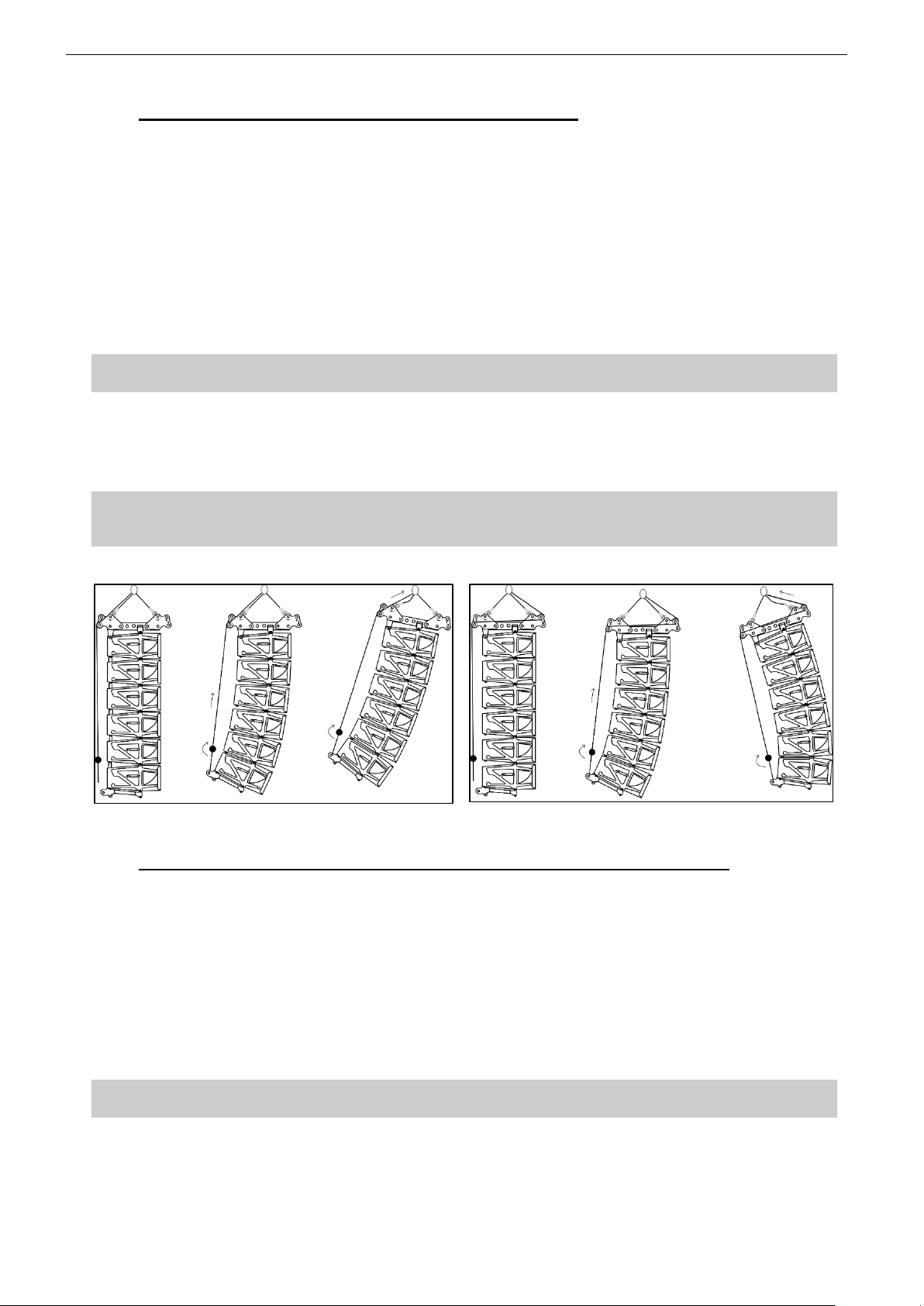
5.10 Compression and bumper angle with a single motor
o Attach the lower hook of the Chain Lever Hoist VXT-LEVA to the rear of BTBUMPER or BCOUP2 (BCOUP3)
o Rotate Chain Lever Hoist wheel clockwise until the BCOUP2 is approximatively parallel with the ground and
the chain is taught
o Make a final check that the Chain Lever Hoist VXT-LEVA is correctly installed
o Rotate the lever to apply pull up force to the bottom of the array. The rear motor hoist may now be raised to
apply the pull-up force to the bottom of the array. Notice that, as the chain gets shorter, the cabinets in the
array close together to piston / compass preset angle
o Once all of the cabinets are closed together, continuing rotating the lever will tilt the bumper up
o Adjust the aiming angle of the array according to the inclinometer display
o Store surplus chain in the chain bag. The chain bag should be clipped to the chain
IMPORTANT
DO NOT attempt to make any changes to the piston angles when the rear pull-up force is applied.
o Adjust the overall height of the array by lifting the motor hoist
o Install secondary safety steel between one PTILT hole marked ∆∆ and a suitable point in the supporting
structure
IMPORTANT
The requirements for secondary safety systems vary with territories. However, the secondary safety steel
MUST have a SWL equivalent to or greater than that of the rigging system
Applying compression and adjusting bumper angle: left for bumper negative tilt, right for bumper positive tilt
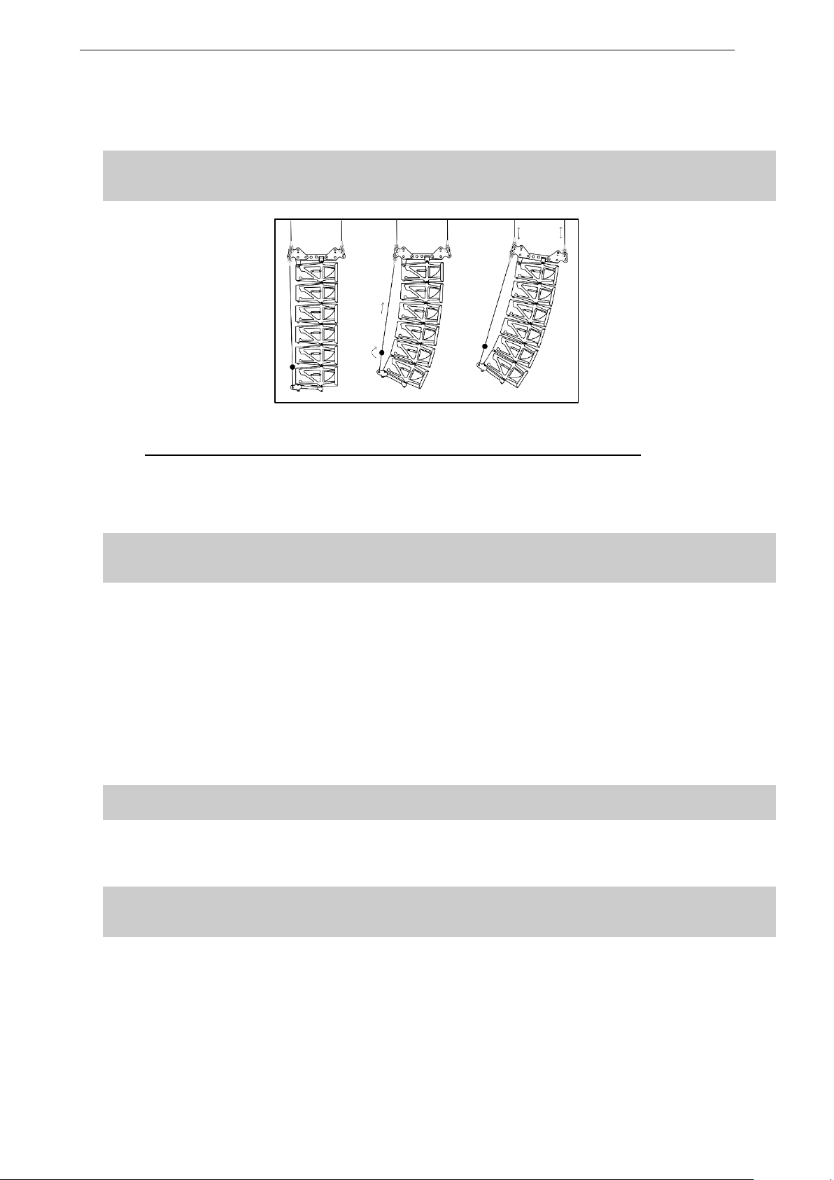
5.11 Compression and bumper angle with 2 motors and a chain lever hoist
o Attach the lower hook of the Chain Lever Hoist VXT-LEVA to the rear of BTBUMPER or BCOUP2 (BCOUP3)
o Rotate the finger wheel clockwise until the BCOUP2 is approximatively parallel with the ground and the chain
is taught
o Make a final check that the Chain Lever Hoist VXT-LEVA is correctly installed
o Rotate the lever to apply pull up force to the bottom of the array. Notice that, as the chain gets shorter, the
cabinets in the array close together to piston/compass preset angles
o When all of the cabinets are closed together, required force to rotate the lever becomes much stronger. This is
the indication that the angles have been correctly set
o Store surplus chain in the chain bag. The chain bag should be clipped to the chain
IMPORTANT
DO NOT attempt to make any changes to the piston angles when the rear pull-up force is applied
Page 39
STM SYSTEM DEPLOYMENT PROCEDURE Page 39/62
o Adjust the overall height and aiming angle of the array by adjusting the front and rear motor hoists accordingly
o Install secondary safety steel between one PTILT hole marked ∆∆ and a suitable point in the supporting
structure
IMPORTANT
The requirements for secondary safety systems vary with territories. However, the secondary safety steel
MUST have a SWL equivalent to or greater than that of the rigging system
Applying compression and adjusting bumper angle
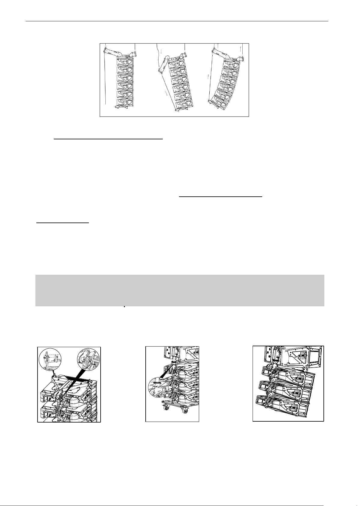
5.12 Compression and bumper angle with 2 motors and kelping chain
o With the cluster raised of the ground, lower the rear motor hoist only. The array will swing slowly forwards until
the centre of gravity lies directly below the front motor hoist. Continue to lower the rear motor hoist and the the
Kelping Beam KBEAM will swing downwards towards the cabinets. Stop lowering the rear hoist when the
Kelping Beam KBEAM is at its lower position.
IMPORTANT
When lowering rear motor hoist, the cluster swings forward: ensure there is no obstacle in front of the
cluster within sufficient distance
o Attach the lower hook of the Kelping Chain to the rear of BTBUMPER or BCOUP2 (BCOUP3)
o Manually raise the Bottomcoupler BCOUP2 (BCOUP3) until it is approximately parallel with the ground
o Set the adjustable clutch in the Kelping Chain BCCH so that the chain is taught
o Make a final check that the Kelping Chain BCCH is correctly installed and store the surplus chain in the chain
bag supplied. The chain bag should be clipped to the clutch adjuster assembly
o The rear motor hoist may now be raised to apply the pull-up force to the bottom of the array. Notice that, as the
rear hoist is raised, the cabinets in the array close together to piston preset angles
o When all of the cabinets are closed together the array begins to move as a whole. This is the indication that
the angles have been correctly set. Ensure that compression has been fully applied to all cabinets by controlling
that Kelping Beam KBEAM is not at its maximum upper position
IMPORTANT
DO NOT attempt to make any changes to the piston angles when the rear pull-up force is applied
o Adjust the overall height and aiming angle of the array by adjusting the front and rear motor hoists accordingly
o Install a secondary safety steel between the Kelping Beam front hole marked ∆∆ and a suitable point in the
supporting structure
IMPORTANT
The requirements for secondary safety systems vary with territories. However, the secondary safety steel
MUST have a SWL equivalent to or greater than that of the rigging system
Page 40
Page 40/62 STM SYSTEM DEPLOYMENT PROCEDURE
Applying compression and adjusting bumper angle
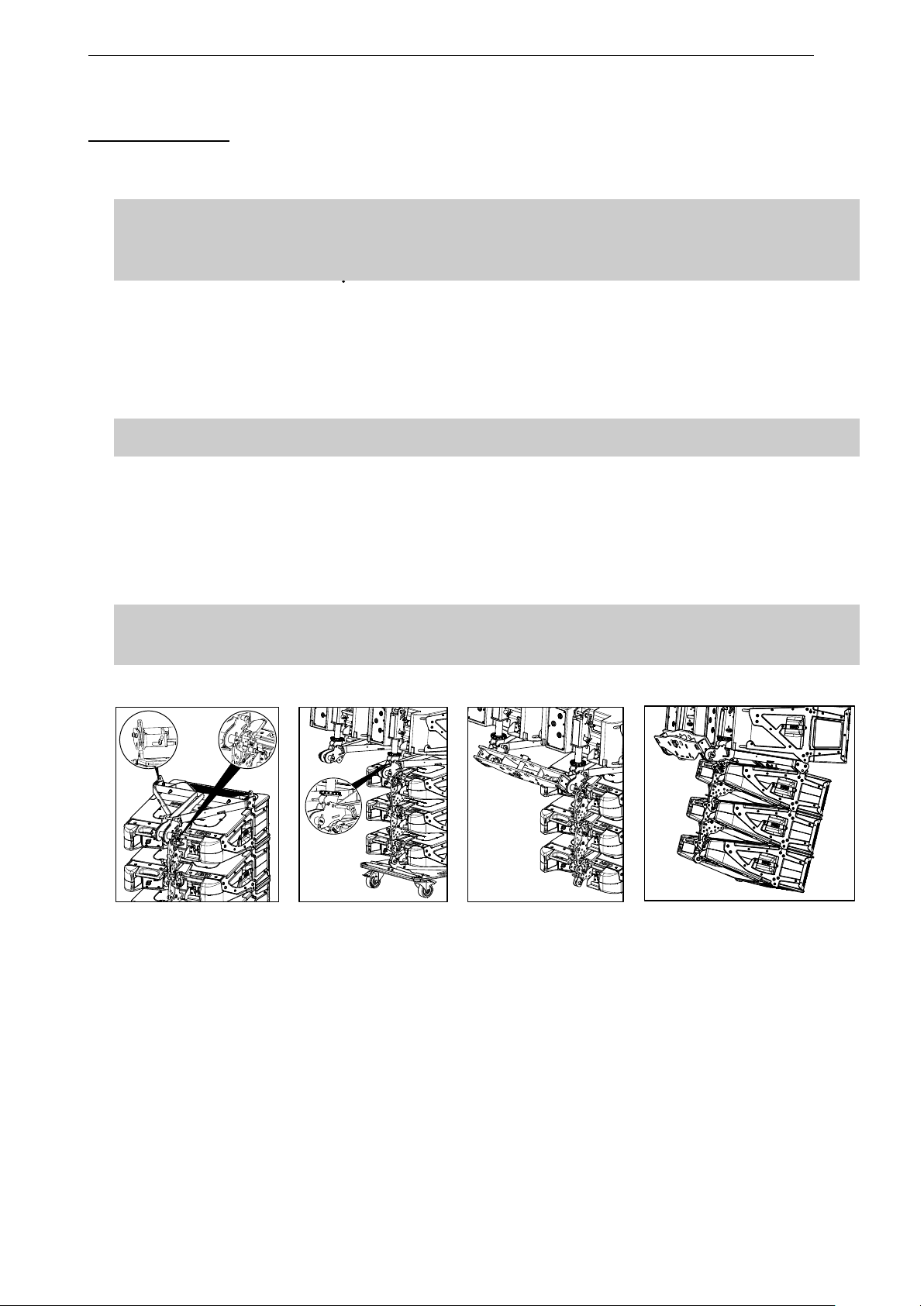
5.13 Adding M28 as a downfill for M46
Up to 3xM28 modules can be added below bottom M46 module in order to extend front coverage.
M28s can be added below bottom bumper in tension mode,
Angle between bottom M46 and first M28 is forced at 10°, angle between subsequent M28s ranges from 10°
to 15°.
NB: M28 cannot be flown below triple column clusters
Once M46 and B112 modules are off the ground and before bottom bumper is installed – ie before compression
is applied -.
Single STM column
o Connect BTBUMPER on top of M28 first downfill by locking the front points and with M46TOM28 for the rear
point
o Bring M28 dolly package below M46 column and lower cluster so that front connecting points of BTBUMPER
and lower M46 module are aligned
o Lock front pins by pushing REDLOCK™ into “LOCK” position; ensure REDLOCK™ safety pins are locked into
handle holes.
IMPORTANT
Side locking pins must be flush to rigging plates on both sides of the cabinets
If locking pins appear to be going inwards in relation to rigging plates, cabinets must not be flown
Ensure REDLOCK™ safety pin are locked into handle holes
o Rotate lock handle of bottom M46 module in “OPERATION” mode (vertical position) in order to disengage
PISTONRIG™
o Connect PISTONRIG™ to BTBUMPER
o apply compression according to preceding sections
Page 41
STM SYSTEM DEPLOYMENT PROCEDURE Page 41/62
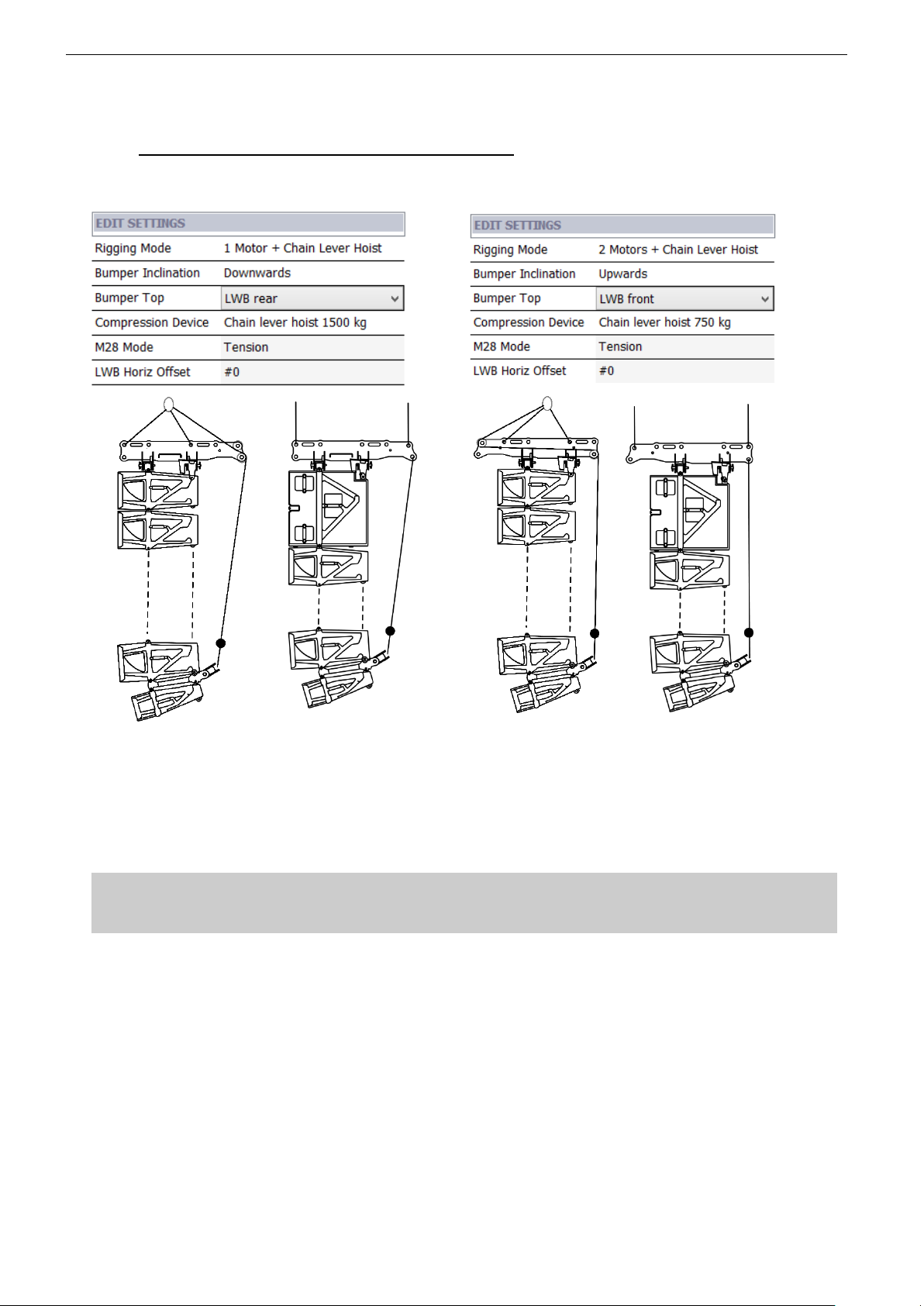
Double STM column
Proceed as above, but prior to applying compression:
o lock the second BTBUMPER to bottom B112 module by pushing RedLock.
IMPORTANT
Side locking pins must be flush to rigging plates on both sides of the cabinets
If locking pins appear to be going inwards in relation to rigging plates, cabinets must not be flown
Ensure REDLOCK™ safety pins are locked into handle hole
o Slide bottom B112 module pistons to bottom bumper connection point by rotating lock handle of the last cabinet
in OPERATION mode (vertical position), and insert quick release pin
o Turn bottom B112 module piston wheel to ■ parking position
o Lift BTBUMPER so that it is adjacent to bottom cabinets and lock them by turning piston lock handle to
“STORAGE” (horizontal position)
IMPORTANT
Check rear quick release pins are fully engaged and locked
o Insert bottom bumper coupler BCOUP2 (BCOUP3) into the 2 (3) fixing points located at the back of the
BTBUMPERs
o Insert the steel pins into the corresponding holes
o Insert safety pins into steel pin hole and lock safety pin by rotating its ring around steel pin
o Check that all elements are properly locked
IMPORTANT
Ensure safety pins springs are functional
Ensure BCOUP2 (BCOUP3) is properly locked to BTBUMPERs, and can be articulated around its axis
o apply compression according to preceding sections
Page 42
Page 42/62 STM SYSTEM DEPLOYMENT PROCEDURE
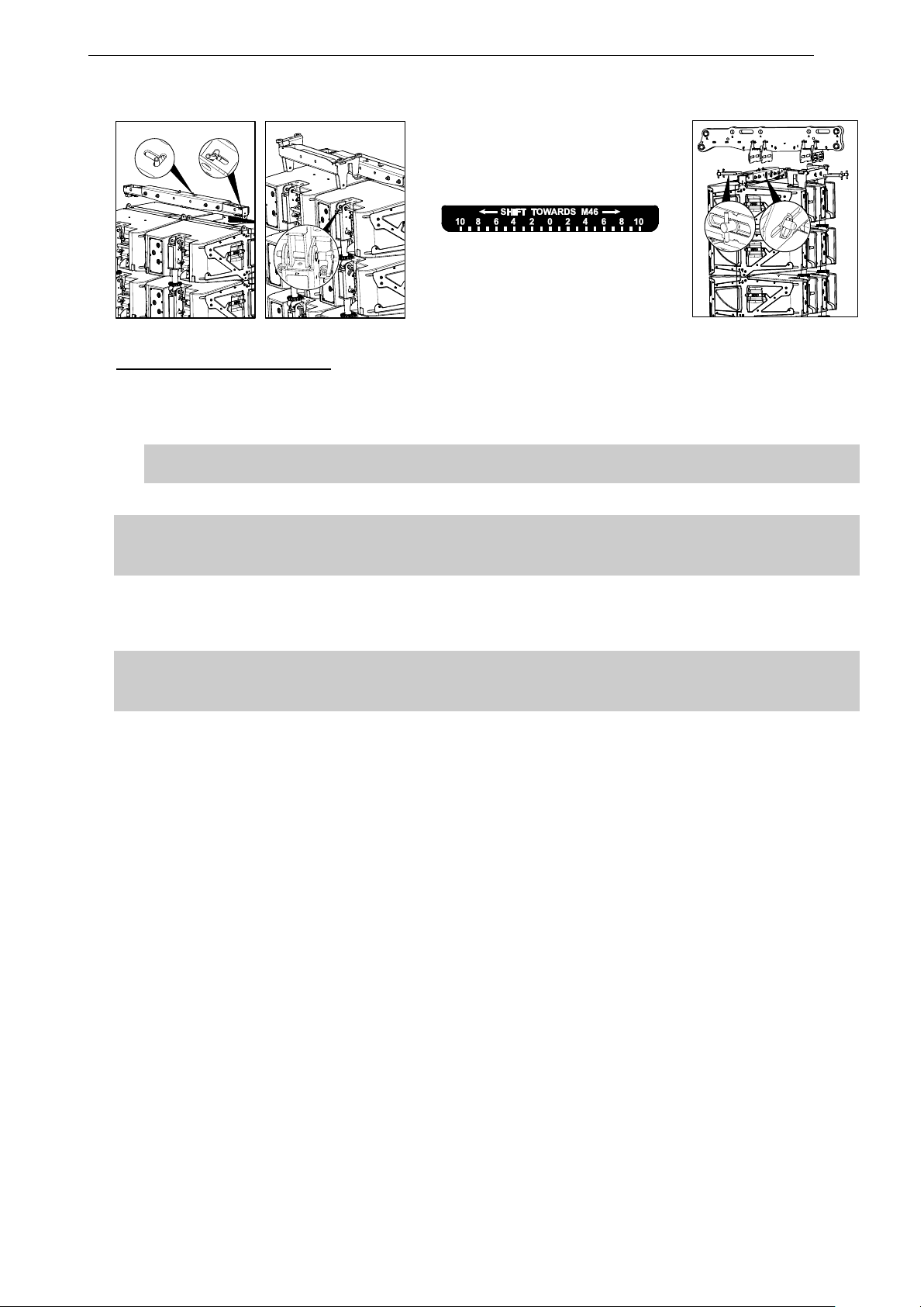
5.14 Special case: flying with lightweight bumper
For small and mid-size STM applications (up to 12 B112 and M46 modules and 3 M28), a specific lightweight bumper
LBUMPER is available.
o Position LBUMPER front beam on top of the two STM modules
o Lock the 4 lateral spring pins into the front lateral holes of STM modules
o Position LBUMPER rear beam on top of the two STM modules
o Insert the 2 quick release pins at the back, in the holes located at the rear of STM modules
IMPORTANT
Ensure LBUMPER front beam springs are functional
Ensure LBUMPER spring pins and rear quick release pin are properly locked into top modules
o Position LBUMPER rigging beam perpendicular to front and rear beams, frontwards or rearwards depending
on anticipated positive or negative bumper angle
o Adjust LBUMPER rigging beam laterally according to NS1 “LWB Horiz Offset” value
o Insert the 4 pins VGOUP16 once rigging beam is adjusted, and secure with the safety pins
Page 43
STM SYSTEM DEPLOYMENT PROCEDURE Page 43/62
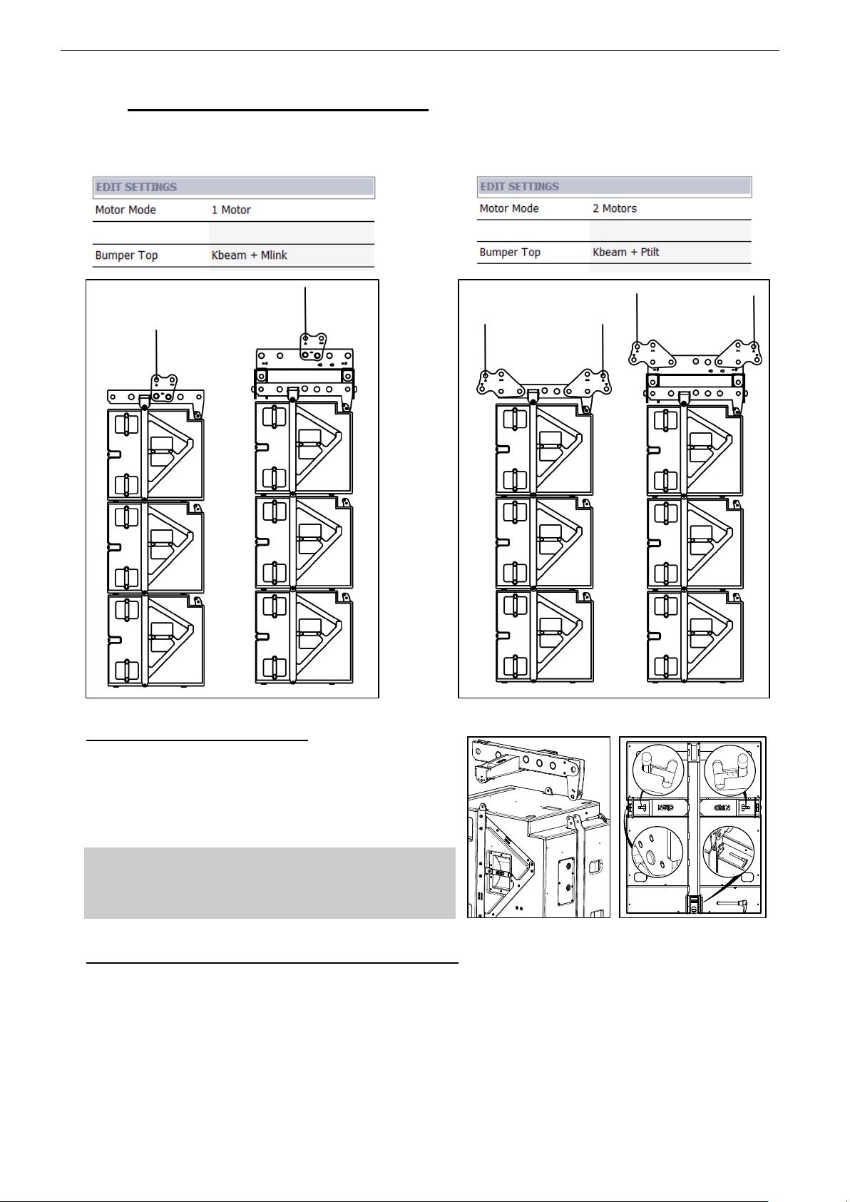
Finalizing the setup LBUMPER
o Insert centring devices into LBUMPER rigging points ∆ (1 unit), then lock these components by inserting the
steel pin into the corresponding hole
o Insert safety pins into steel pin hole and lock safety pin by rotating its ring around steel pin
IMPORTANT
Ensure safety pins springs are functional
o Attach motor hoists to centring devices
IMPORTANT
Both motor hoists must be rated for total cluster weight
Please refer to NS1 mechanical information
o Insert centring devices into LBUMPER lower compression point (1 unit), then lock these components by
inserting the steel pins into the corresponding holes
o Attach chain lever hoist hook to LBUMPER lower centring device
IMPORTANT
Compression chain must be rated according to compression pullback force
Please refer to NS1 mechanical information
o If top modules are on a dolly, unlock the dolly by pulling bottom cabinet RedLock handle
o Lift assembly slightly off the ground (and store dolly)
o And proceed as in above sections to connect modules, attach bottom bumper and apply compression
Page 44
Page 44/62 STM SYSTEM DEPLOYMENT PROCEDURE
5.15 Special case: flying S118 only clusters
When flying S118 only in single or multiple columns, and provided bumper angle is forced to 0° (horizontal),
compression procedure is no longer required.
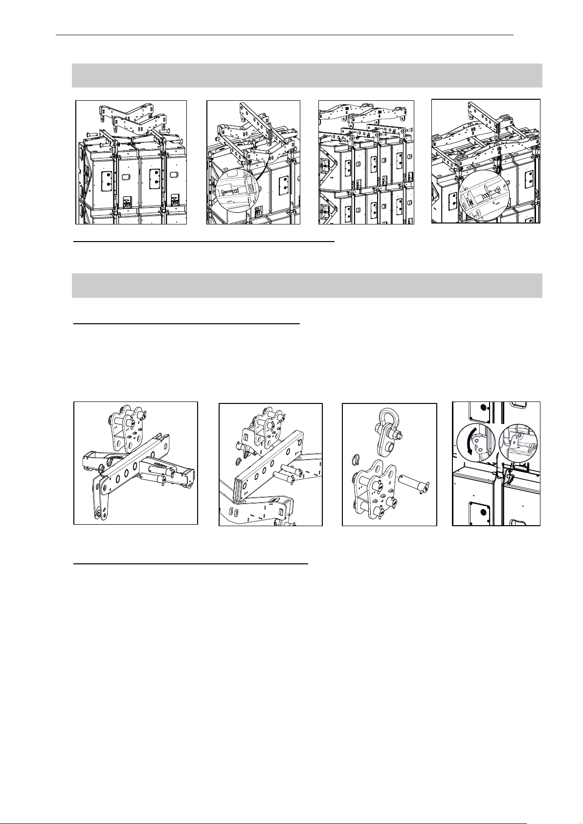
Connecting XBOW to the top S118
o Insert the XBOW into the 3 fixing points: 2 on the sides
and one at the back of the S118
o Lock the lateral spring pins located inside the XBOW to
the front lateral holes of the S118
o Insert quick release pin at the back
IMPORTANT
Ensure XBOW springs are functional
Ensure-XBOW lateral spring pins and rear quick release
pin are properly locked into top cabinet
Connecting XBOW to XCOUP2 (XCOUP3) coupling beams
o Insert front coupling beam XCOUP2 (XCOUP3) into left and right XBOWs, then lock these 2 components by
inserting the steel pins into the corresponding holes
o Insert safety pins into steel pins hole and lock safety pin by rotating its ring around steel pin
o Repeat the same procedure for the rear coupling XCOUP2 (XCOUP3)
Page 45
STM SYSTEM DEPLOYMENT PROCEDURE Page 45/62
IMPORTANT
Ensure assembly is properly locked on these 4 (6) points
Connecting MBEAM to XCOUP2 (XCOUP3) coupling beams
o Insert the MBEAM fixing points into XCOUP2 (XCOUP3) coupling beams then release XCOUP2 (XCOUP3)
spring pins so that above components are locked
IMPORTANT
Ensure-XCOUP2 (XCOUP3) spring pins are properly locked into MBEAM
One motor: connecting MLINK to XBOW or MBEAM
o Position MLINK at the middle of XBOW or MBEAM then lock these components by inserting steel pins into the
corresponding holes
o Insert centring device into MLINK main rig point ∆ (1 unit), then lock these 2 components by inserting the steel
pin into the corresponding hole
o Insert safety pins into steel pins holes and lock safety pin by rotating its ring around steel pin
Connecting MLINK to XBOW or MBEAM Centring Device Linking S118s
Two motors: connecting PTILTS to XBOW or MBEAM
o Position first PTILT to the front of XBOW or MBEAM then lock these components by inserting steel pins into
the corresponding holes
o Insert safety pins into steel pins holes and lock safety pin by rotating its ring around steel pin
Page 46
Page 46/62 STM SYSTEM DEPLOYMENT PROCEDURE
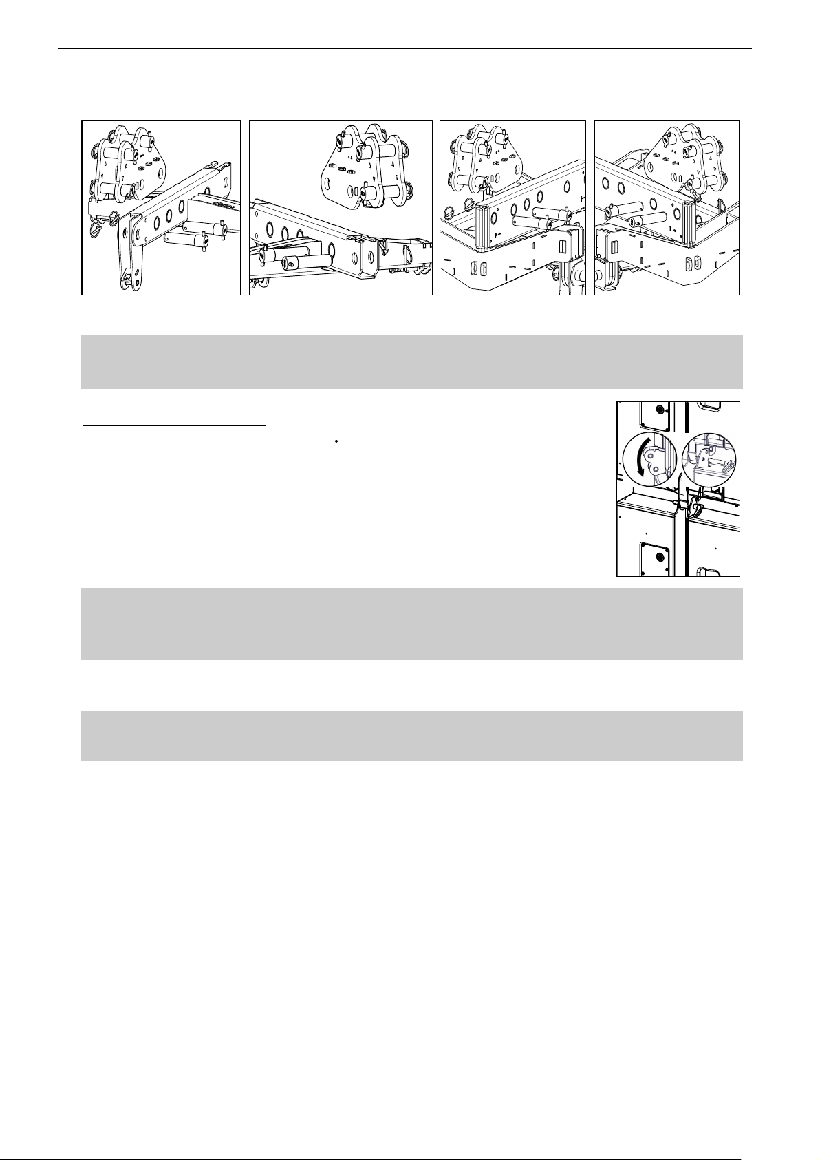
o Position second PTILT to the rear of XBOW or MBEAM then repeat the same safety procedure than above
Connecting PTILTs to XBOW Connecting PTILTs to MBEAM
IMPORTANT
Ensure safety pins springs are functional;
Ensure PTILTs or MLINK are properly locked to XBOW or MBEAM
Connecting subsequent S118
o Lift upper S118 assembly so that next dolly package can roll underneath
o Align second dolly package below upper assembly
o Lower upper assembly into position, aligning side rigging slots on both sides of the
cabinets
o In order to connect upper assembly to the second set of cabinets, push REDLOCK™
into “LOCK” position; ensure REDLOCK™ safety pins are locked into handle holes
o insert rear quick release pin on the rear hinge so that upper set is connected to lower
set
IMPORTANT
Side locking pins must be flush to rigging plates on both sides of S118
If locking pins appear to be going inwards in relation to rigging plates, S118 must not be flown
Check rear quick release pins are fully engaged and locked
o Repeat the same procedures as before until the full array is off the ground
o Install a secondary safety steel between the MLINK or PTILTs and a suitable point in the supporting structure
IMPORTANT
The requirements for secondary safety systems vary with territories. However, the secondary safety steel
MUST have a SWL equivalent to or greater than that of the rigging system
Page 47

STM S118 TECHNICAL SPECIFICATIONS Page 47/62
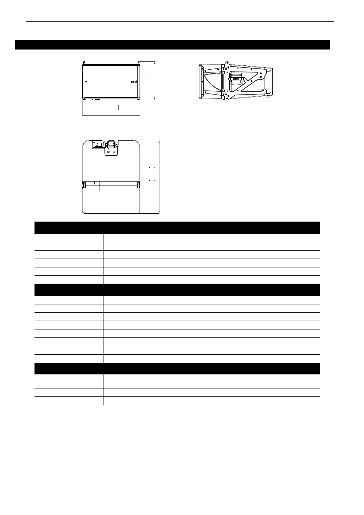
6 STM S118 TECHNICAL SPECIFICATIONS
SYSTEM SPECIFICATIONS
STM S118 with NXAMP 4x4
Frequency Response [a]
27Hz – 85Hz ±3dB
Usable Range @-6dB [a]
23Hz – 100Hz
Sensitivity 1W @ 1m [b]
109dB SPL Nominal
Nominal Peak SPL @ 1m [b]
143dB Peak
Nominal Impedance
16 (12 min)
Amplified Controller
NXAMP4x4 - 3xSTM S118 in parallel on 2 NXAMP4x4 bridged channels – 8000W/4
PRODUCT FEATURES
STM S118
Components :
LF: 1 x 18” (46cm) 3000W high excursion Neodynium16 Ohms driver.
Height x Width x Depth
700 x 575 x 715 mm – 27.56” x 22.64” x 28.15”
Weight : Net
85kg – 187lbs
Connectors
2 x NLT4-MDV Speakon 4 poles (in/out)
Construction
Baltic birch ply finished with structured black coating
Fittings: Handles
6 handles (3 per side)
Front
Perforated Dark Grey Metal Grille
Rigging
Integral 3 points flying and locking system.
SYSTEM OPERATION
Electronic Controller
The NEXO NXAMP4x4 presets are precisely matched to the STM Series cabinets and include sophisticated protection
algorithms.. Using STM Series cabinets without a properly connected NEXO NXAMP4x4 will result in poor sound quality and can
damage components.
Speaker Cabling
1-/1+: SUB - 2-/2+: LF
As part of a policy of continual improvement, NEXO reserves the right to change specifications without notice.
[a] Response curves & data : Half-Space Far Field for the STM S118 & B112 + NXAMP4x4.
[b] Sensitivity & Peak SPL data : these will depend on spectral distribution and crest factor of program material. Measured with band limited Pink Noise. Data are for speaker + amplified
controller. Peak SPL is at clipping of NXAMP4x4.
29,0
736
22,5
572
28,7
730
Page 48
Page 48/62 STM B112 TECHNICAL SPECIFICATIONS
7 STM B112 TECHNICAL SPECIFICATIONS
SYSTEM SPECIFICATIONS
STM B112 with NXAMP 4x4
Frequency Response [a]
63Hz – 200Hz ±3dB
Usable Range @-6dB [a]
55Hz – 250Hz
Sensitivity 1W @ 1m [b]
107dB SPL Nominal
Nominal Peak SPL @ 1m [b]
141dB Peak
Nominal Impedance
16 (12 min)
Amplified Controller
NXAMP4x4 - 3xSTM B112 in parallel on 2 NXAMP4x4 bridged channels – 8000W/4
PRODUCT FEATURES
STM B112
Components :
LF: 1 x 12” (30cm) 3000W high excursion Neodynium16 Ohms driver.
Height x Width x Depth
350 x 575 x 715 mm – 13.78” x 22.64” x 28.15”
Weight : Net
59 kg – 130 lbs
Connectors
2 x NLT4-MDV Speakon 4 poles (in/out)
Construction
PU Composite Low Density – Polyurethane water based black coating
Fittings: Handles
3 handles (2 sides and 1 rear)
Front
Perforated Dark Grey Metal Grille
Rigging
Integral 3 points flying system. Intercabinet angle adjustments from 0.2° to 10° in logarithmic steps.
SYSTEM OPERATION
Electronic Controller
The NEXO NXAMP4x4 presets are precisely matched to the STM Series cabinets and include sophisticated protection algorithms.
Using STM Series cabinets without a properly connected NEXO NXAMP4x4 will result in poor sound quality and can damage
components.
SubBass
STM S118 extends system low frequency response down to 25Hz
Speaker Cabling
1-/1+: SUB - 2-/2+: LF
As part of a policy of continual improvement, NEXO reserves the right to change specifications without notice.
[a] Response curves & data : Half-Space Far Field for the STM S118 & B112 + NXAMP4x4.
[b] Sensitivity & Peak SPL data : these will depend on spectral distribution and crest factor of program material. Measured with band limited Pink Noise. Data are for speaker + amplified
controller. Peak SPL is at clipping of NXAMP4x4.
22,64
575
28,74
730
15,12
384
Page 49

STM M46 TECHNICAL SPECIFICATIONS Page 49/62
8 STM M46 TECHNICAL SPECIFICATIONS
SYSTEM SPECIFICATIONS
STM M46 with NXAMP 4x4
Frequency Response [a]
85Hz – 19kHz ±3dB
Usable Range @-6dB [a]
80Hz – 20kHz
Sensitivity 1W @ 1m [b]
110dB SPL Nominal
Nominal Peak SPL @ 1m [b]
145dBPeak
Dispersion [c]
90° Horizontal x 0-10° vertical
Crossover Frequency
1.5 kHz
Nominal Impedance
LF-MF:16 (12 min) – HF: 16 (12 min)
Amplified Controller
NXAMP4x4 - 3xSTM M46 in parallel on 2 NXAMP4x4 channels – 2x4000W/2
PRODUCT FEATURES
STM M46
Components :
LF-MF: 4 x 6.5” (17cm) 16 flat membrane high excursion drivers.
HF: 4 x 2.5” voice coil, 1.4” throat Neodynium 16 drivers, Ketone Polymer diaphragm
Height x Width x Depth
350 x 575 x 715 mm – 13.78” x 22.64” x 28.15”
Weight : Net
59kg – 130lbsb
Connectors
2 x NL8-MDV Speakon 8 poles (in/ou t) & 1 x NLT4-MDV Speakon 4 poles (to STM S118 and B112)
Construction
PU Composite Low Density – Polyurethane water based black coating
Fittings: Handles
3 handles (2 sides and 1 rear)
Front
Perforated Dark Grey Metal Grille
Rigging
Integral 3 points flying system. In tercabinet angle adjustments from 0.2° to 10° in logarithmic steps.
SYSTEM OPERATION
Electronic Controller
The NEXO NXAMP4x4 presets are precisely matched to the STM Series cabinets and include sophisticated protection algorithms.
Using STM Series cabinets without a properly connected NEXO NXAMP4x4 will result in poor sound quality and can damage
components.
SubBass
STM S118 extends system low frequency response down to 25Hz
Speaker Cabling
1-/1+: SUB - 2-/2+: LF – 3-/3+: LF-MF 4-/4+: HF
As part of a policy of continual improvement, NEXO reserves the right to change specifications without notice.
[a] Response curves & data : Half-Space Far Field for the STM S118 & B112 + NXAMP4x4.
[b] Sensitivity & Peak SPL data : these will depend on spectral distribution and crest factor of program material. Measured with band limited Pink Noise. Data are for speaker + amplified
controller. Peak SPL is at clipping of NXAMP4x4.
[c] Directivity curves & data : obtained by computer treatment on off axis response curves.
28,7
730
15,1
384
22,6
575
Page 50
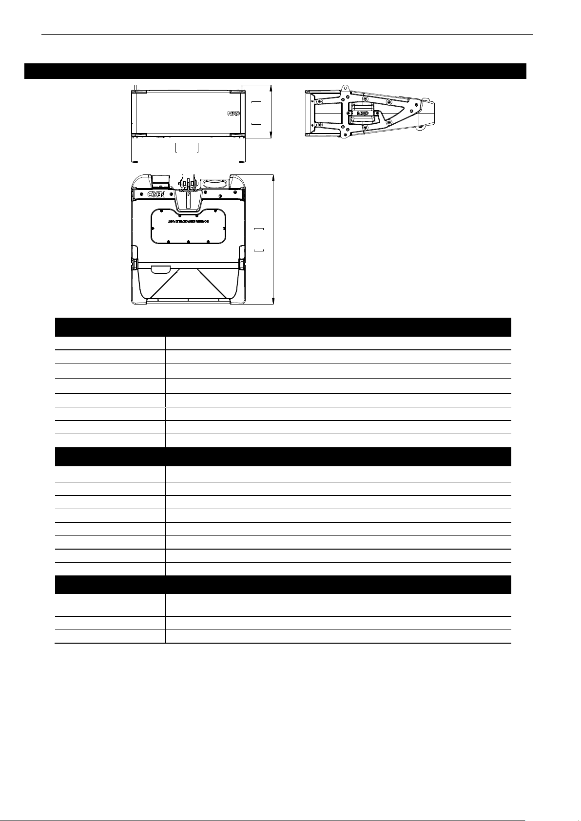
Page 50/62 STM M28 TECHNICAL SPECIFICATIONS
9 STM M28 TECHNICAL SPECIFICATIONS
SYSTEM SPECIFICATIONS
STM M28 with NXAMP 4x4
Frequency Response [a]
65Hz – 19kHz ±3dB
Usable Range @-6dB [a]
60Hz – 20kHz
Sensitivity 1W @ 1m [b]
106dB SPL Nominal (120° horizontal coverage)
107 dB SPL Nominal (90° horizontal coverage)
Nominal Peak SPL @ 1m [b]
140dBPeak (120° horizontal coverage)
141 dB Peak (90° horizontal coverage)
Dispersion [c]
Configurable 90°-120° Horizontal x 0-15° vertical
Crossover Frequency
900Hz (Active)
Nominal Impedance
LF: 8 (6 min) - HF: 8 (6 min)
Amplified Controller
NXAMP4x4 - 3xSTM M28 in parallel on 2 NXAMP4x4 channels – 2x4000W/2
PRODUCT FEATURES
STM M28
Components :
LF: 2 x 8” (20cm) high excursion 16 Neodynium drivers
HF: 2 x 2.5” voice coil, 1.4” throat Neodynium 16 drivers, Ketone Polymer diaphragm
Height x Width x Depth
234 x 575 x 653 mm – 9.2” x 22.64” x 25.7”
Weight : Net
37 kg – 82lbs
Connectors
2 x NLT4-MDV Speakon 4 poles
Construction
PU Composite Low Density – Polyurethane water based black coating
Fittings: Handles
3 handles (2 sides and 1 rear)
Front
Perforated Dark Grey Metal Grille
Rigging
Integral 3 points flying system. Intercabinet angle adjustments from 0.2° to 15° in logarithmic steps.
SYSTEM OPERATION
Electronic Controller
The NEXO NXAMP4x4 presets are precisely matched to the STM Series cabinets and include sophisticated protection algorithms.
Using STM Series cabinets without a properly connected NEXO NXAMP4x4 will result in poor sound quality and can damage
components.
SubBass
STM S118 extends system low frequency response down to 25Hz
Speaker Cabling
1-/1+: LF - 2-/2+: HF
As part of a policy of continual improvement, NEXO reserves the right to change specifications without notice.
[a] Response curves & data : Half-Space Far Field for the STM S118 & B112 + NXAMP4x4.
[b] Sensitivity & Peak SPL data : these will depend on spectral distribution and crest factor of program material. Measured with band limited Pink Noise. Data are for speaker + amplified
controller. Peak SPL is at clipping of NXAMP4x4.
[c] Directivity curves & data : obtained by computer treatment on off axis response curves.
10,5
267
22,6
575
25,7
653
Page 51
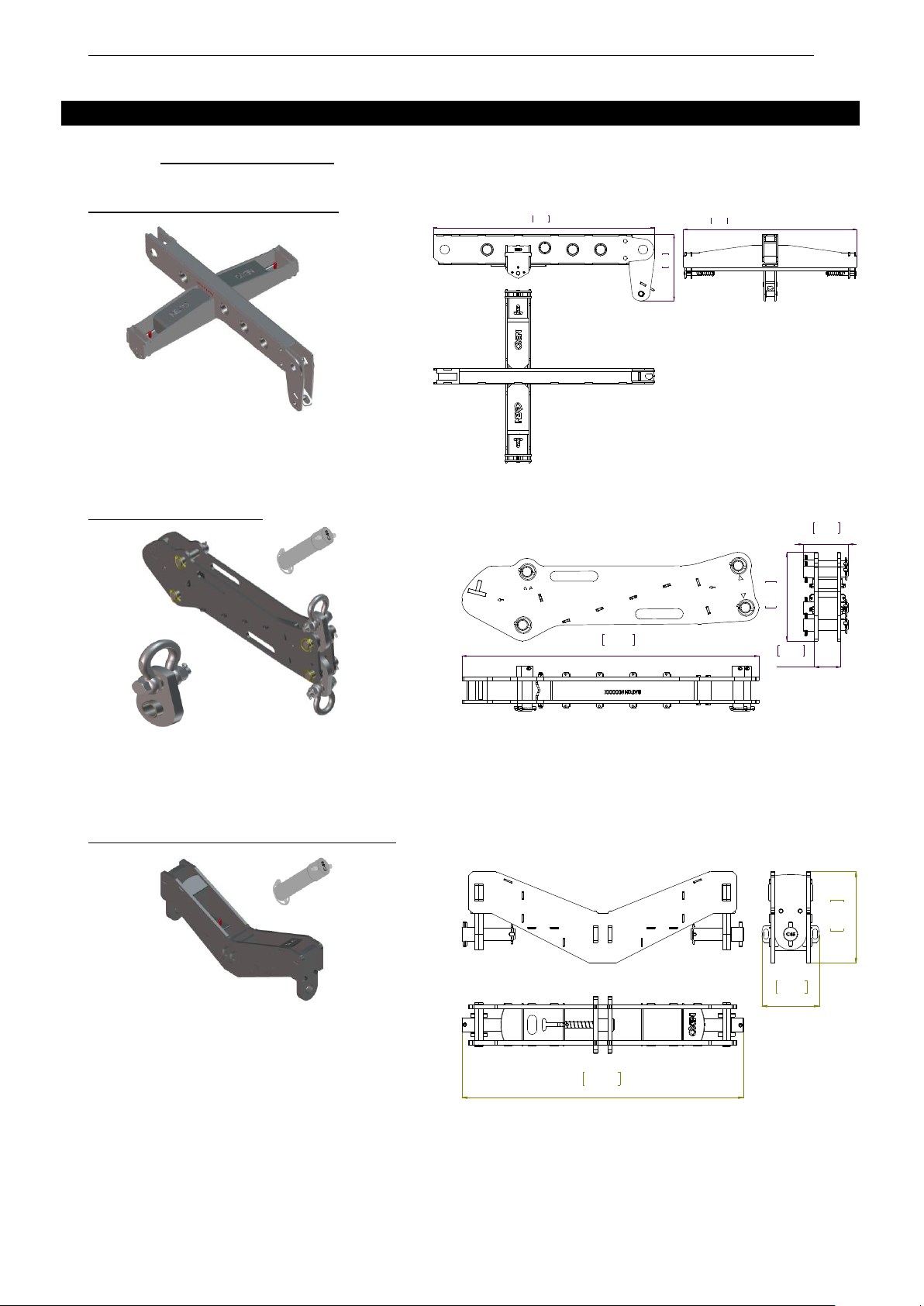
STM ACCESSORIES Page 51/62
10 STM ACCESSORIES
10.1 Rigging accessories
XBOW - single column top bumper
Item: 1 x unit
Weight: 16kg / 35lb
KBEAM – Kelping beam
Items: 1 x unit + 4 x C45 Ø30mm pins + 2 x centring devices
Weight: 26kg / 57lb (without centring device)
XCOUP2 - double column top coupling bar
Items: 2 x units + 4 x C45 Ø30mm pins
Weight: 20kg / 44lb
8,58
218
28,74
730
22,52
572
9,81
249
2,91
74
4,99
127
32,87
835
8,67
220
5,43
138
26,64
677
Page 52

Page 52/62 STM ACCESSORIES
XCOUP3 - triple column top coupling bar
Items: 2 x units + 6 x C45 Ø30mm pins
Weight: 34kg / 75lb
MBEAM – 2 and 3 columns flying beam
Items: 1 x unit
Weight: 19kg / 42lb (without centring device)
PTILT – front / rear motor rigging point
Items: 1 x unit + 5 x C45 Ø30mm pins + 1 x centring devices + 1 x nylon wheel
Weight: 12kg / 26lb (without centring device)
MLINK – center motor rigging point
5,43
138
9,77
248
50,06
1272
9,51
241
1,97
50
28,70
729
14,10
358
2,91
74
4,99
127
8
,3
6
2
1
2
Page 53
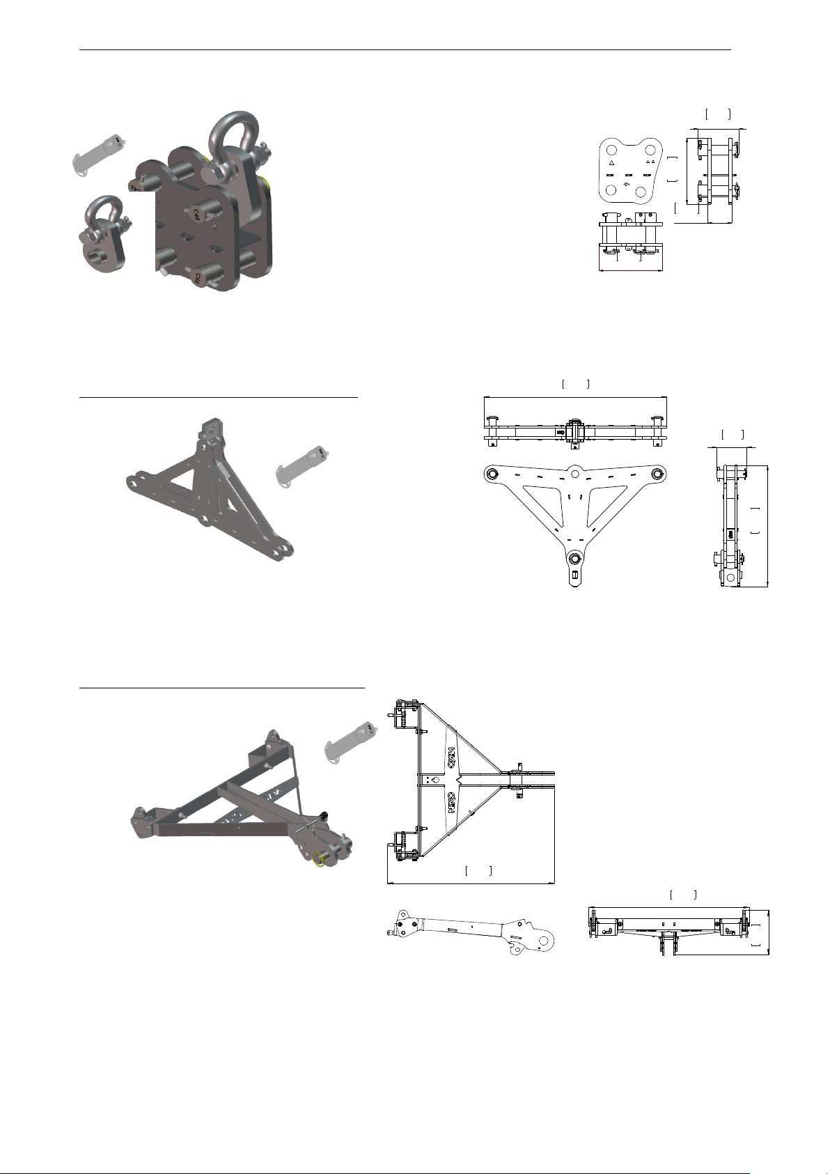
STM ACCESSORIES Page 53/62
Items: 1 x unit + 4 x C45 Ø30mm pins + 1 x centring device
Weight: 8kg / 18lb (without centring device)
DPLATE – Delta plate for horizontal aiming
Items: 1 x unit + 3 x C45 Ø30mm pins + 1 x centring device
Weight: 24kg / 53lb (without centring device)
BTBUMPER - single column bottom bumper
Items: 1 x unit + 1 x C45 Ø30mm pin
Weight: 10kg / 22lb
7,76
197
2,91
74
4,99
127
8
,0
7
2
0
5
4,99
127
2
0
,2
8
5
1
5
30,51
775
22,65
575
6,33
161
23,53
598
Page 54
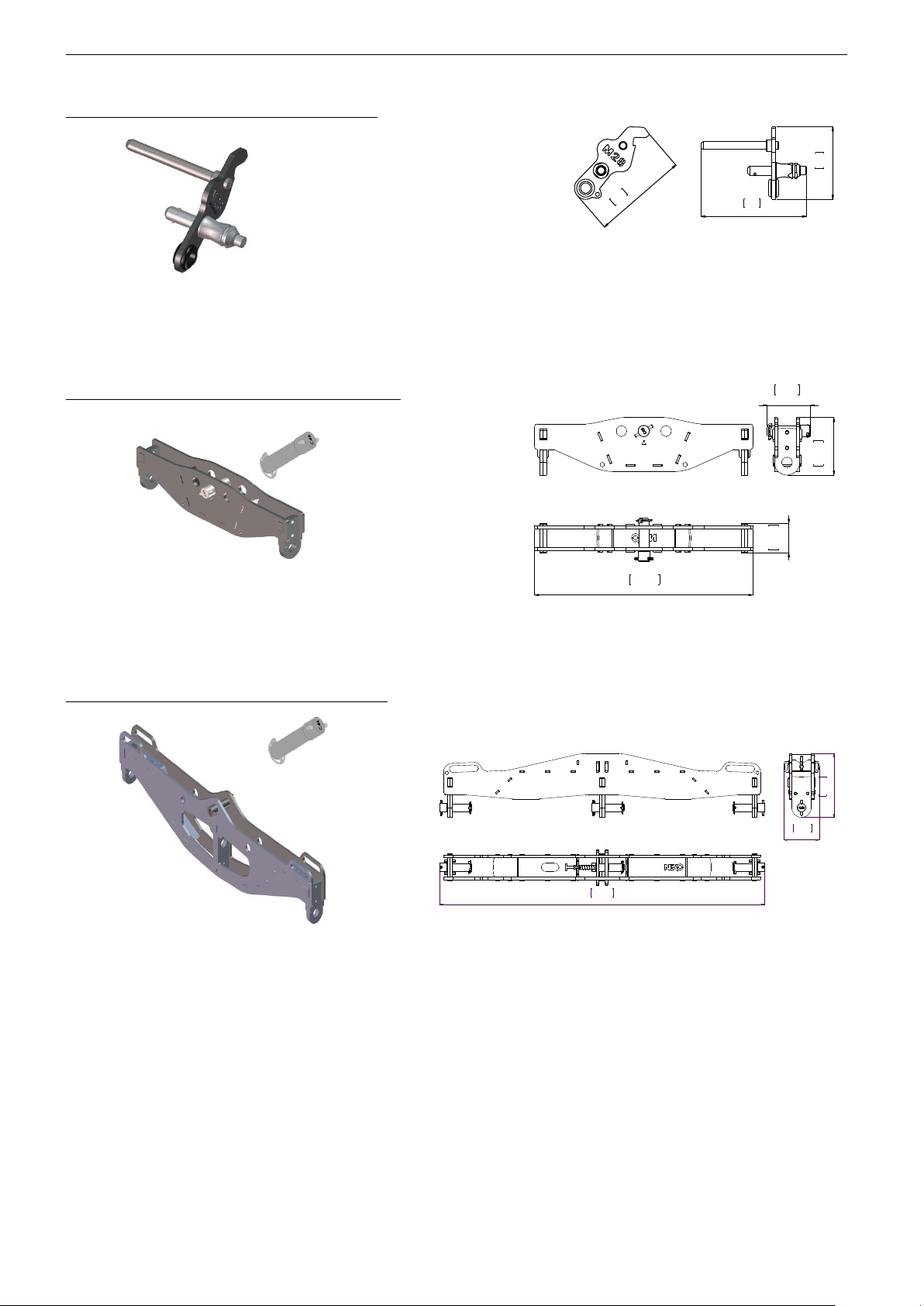
Page 54/62 STM ACCESSORIES
M46TOM28 – M28 Bottom bumper adaptor
Item: 1 x unit
Weight: 1kg / 2lb (without centring device)
BCOUP2 - double column bottom coupling bar
Items: 1 x unit + 1 x C45 Ø30mm pin
Weight: 16kg / 35lb
BCOUP3 - triple column bottom coupling bar
Items: 1 x unit + 1 x C45 Ø30mm pin
Weight: 34kg / 75lb
4
,
8
1
2
2
3,7
93
5,3
136
25,39
645
3,43
87
6,69
170
4,99
127
5,43
138
9,77
248
50,06
1272
Page 55
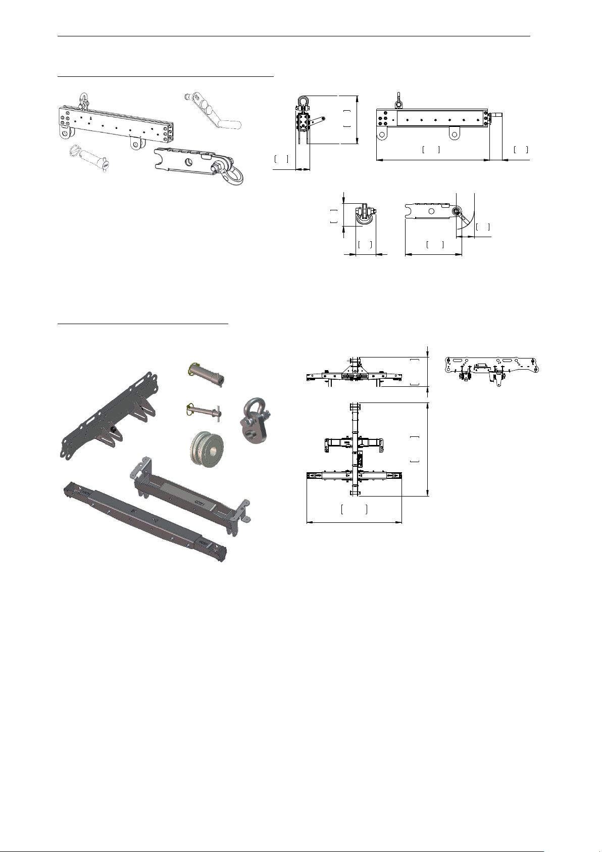
STM ACCESSORIES Page 55/62
VBUMPER – single rigging point Variobumper
Items: 1 x unit+ 3 x C45 Ø30mm pins
Weight: 25 kg / 55 lb
LBUMPER – double column bumper
Items: 1 x unit + 4 x C45 Ø30mm pins + 2 x 4 Vgoup16 + 3 x centring device + 2 x nylon wheels
Weight: 62 kg / 136 lb
31,5
801
3,5
88
3,9
100
13,4
340
12,8
325
4,1
104
5
,1
1
3
0
4,6
116
14,19
360
45,94
1167
45,24
1149
Page 56
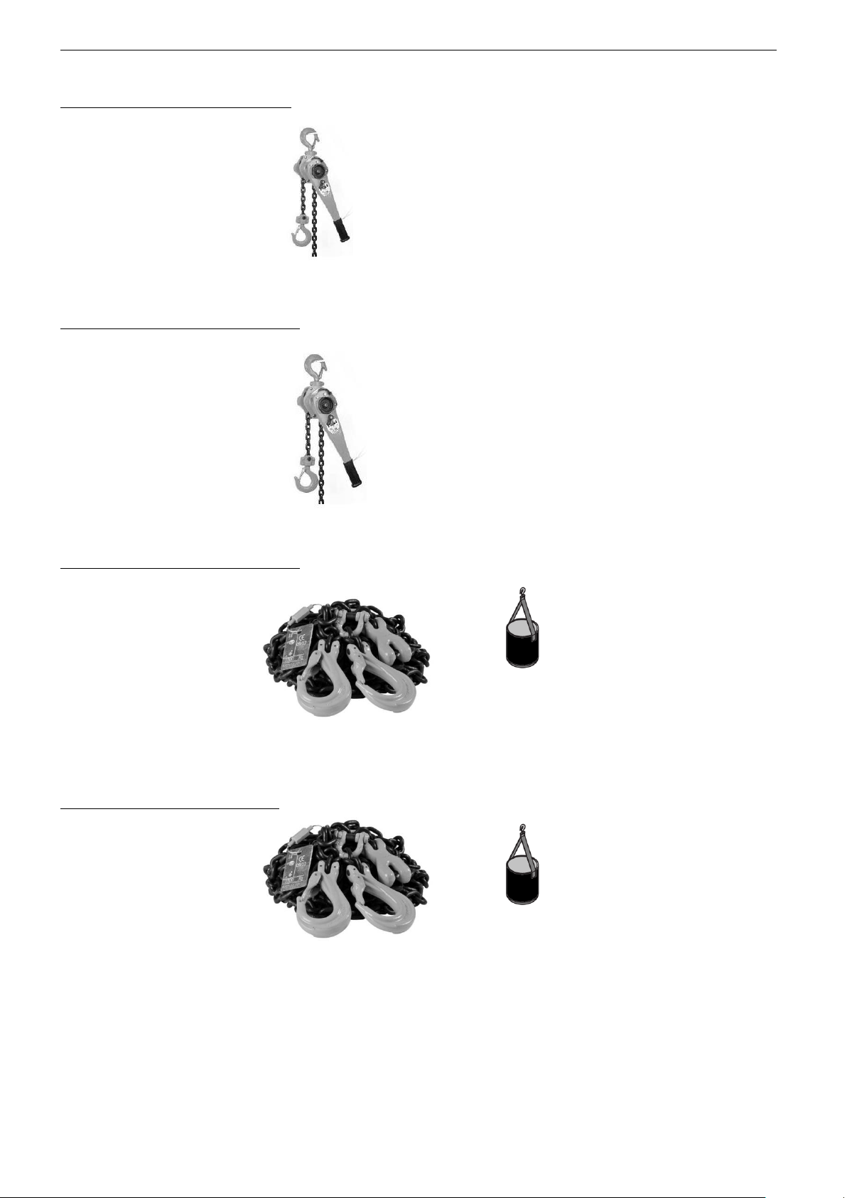
Page 56/62 STM ACCESSORIES
LEVA750 Chain Lever Hoist 750kg
Item= 1 x unit
Weight: 11kg / 24lb
LEVA1500 Chain Lever Hoist 1.5ton
Item : 1 x unit
Weight: 24kg / 53lb
BCCH15 Compression Chain 1.5ton
Items : 1 x unit + 1 chain bag
Weight: 10kg / 22lb – Length: 6m / 20ft
BCCH3 Compression Chain 3ton
Items : 1 x unit + 1 chain bag
Weight: 30kg / 66lb – Length: 9m / 30ft
Page 57
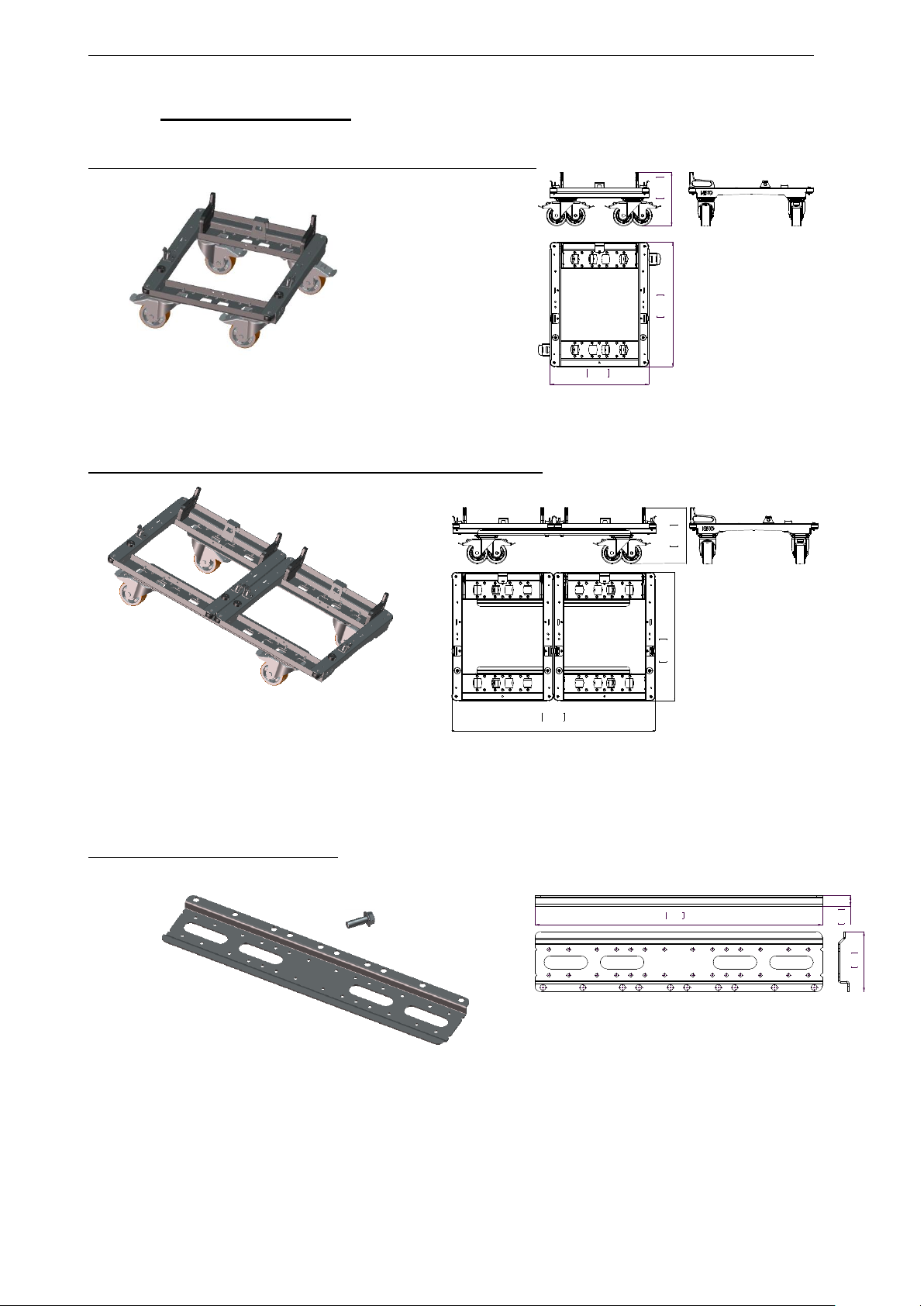
STM ACCESSORIES Page 57/62
10.2 Transport accessories
DOLLY01 – Single dolly for up to 3xM46 or 3xB112 or 2xS118
Items : 1 x unit + 1 x S118 adaptor
Weight: 32kg / 70lb
DOLLY02 – Double dolly for up to 6xM46 or 6xB112 or 4xS118
Items : 1 x unit + 2 x S118 adaptor
Weight: 63kg / 139lb
DCOUP- Coupling Rod for Dolly01
Items : 2 x units + 8 x M1030 screws
Weight: 12kg / 26lb
1
2
,7
5
3
2
4
2
9
,5
3
7
5
0
23,39
594
1
2
,9
5
3
2
9
46,81
1189
2
9
,5
3
7
5
0
1,34
34
35,10
892
7,37
187
Page 58
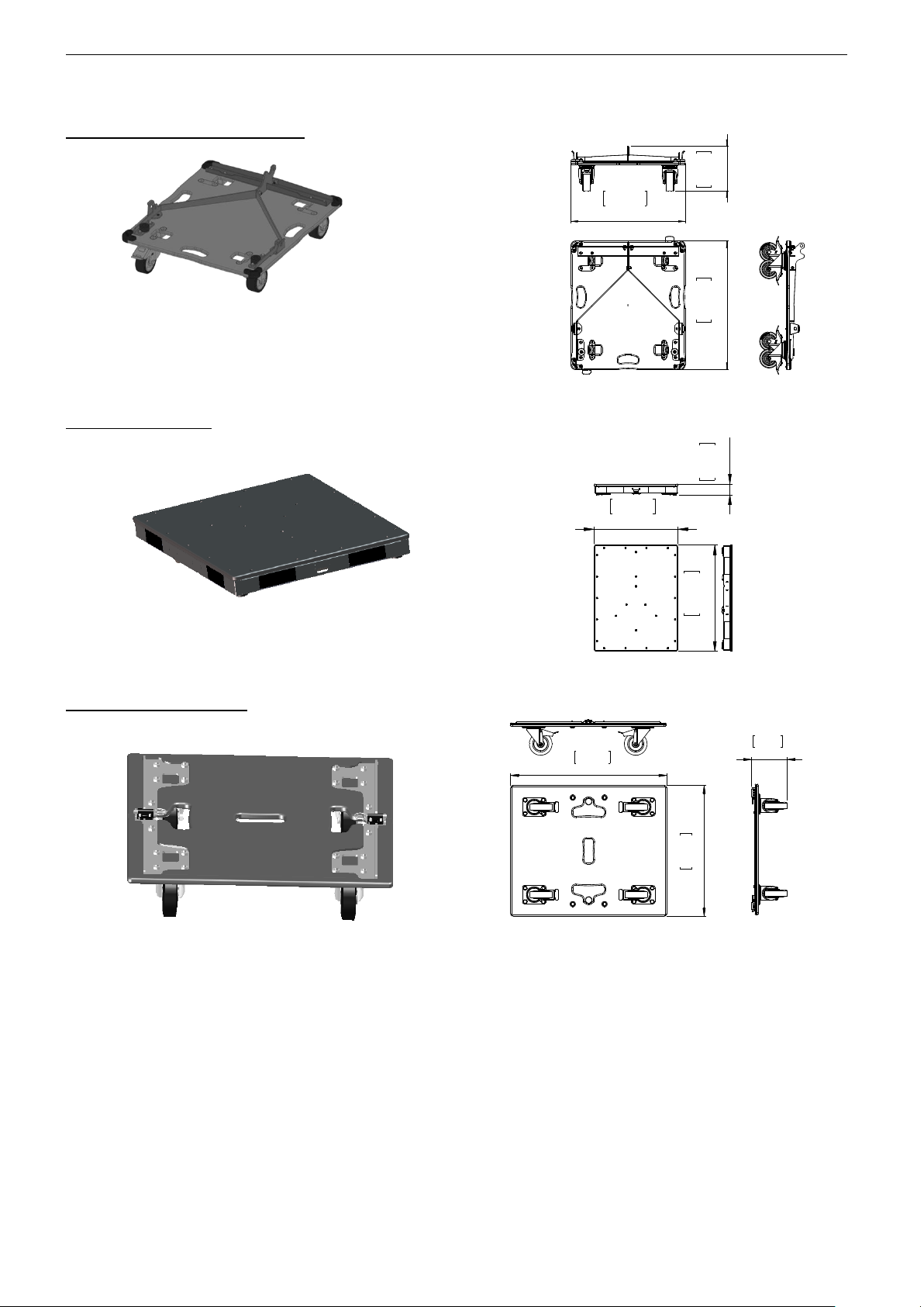
Page 58/62 STM ACCESSORIES
DOLLY03 –Dolly for up to 3xM28
Item : 1 x unit
Weight: 11kg / 24lb
DROOF – Dolly roof
Item: 1 x unit
Weight: 13kg / 29lb
WB02- S118 wheelboard
Item: 1 x unit
Weight: 10kg / 22lb
2
6
,5
7
6
7
5
23,65
601
9
,1
8
2
3
3
23,03
585
2
9
,3
7
7
4
6
2
,9
8
7
6
27,09
688
2
2
,6
4
5
7
5
6,21
158
Page 59
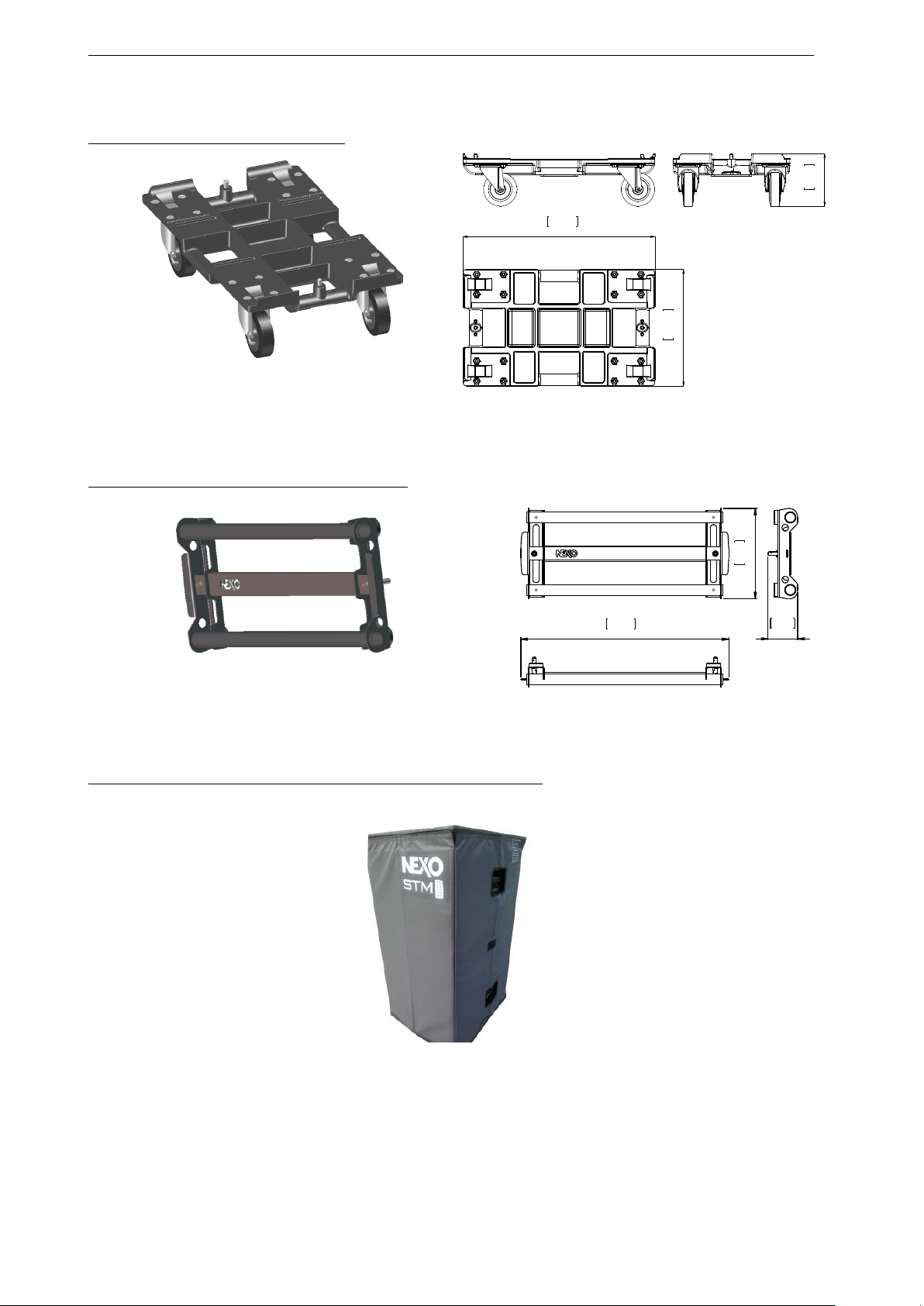
STM ACCESSORIES Page 59/62
WB01 – B112 and M46 wheelboard
Item: 1 x unit
Weight: 6kg / 13lb
FHANDLE – Front handle for B112 and M46
Item: 1 x unit
Weight: 3kg / 7lb
DCOVER01 – Lateral cover for 3xM46 or 3xB112 on DOLLY01
Item: 1 x unit
Weight: 4 kg / 9lb
2,25
57
13,78
350
22,63
575
9,82
250
22,56
573
3,21
82
Page 60
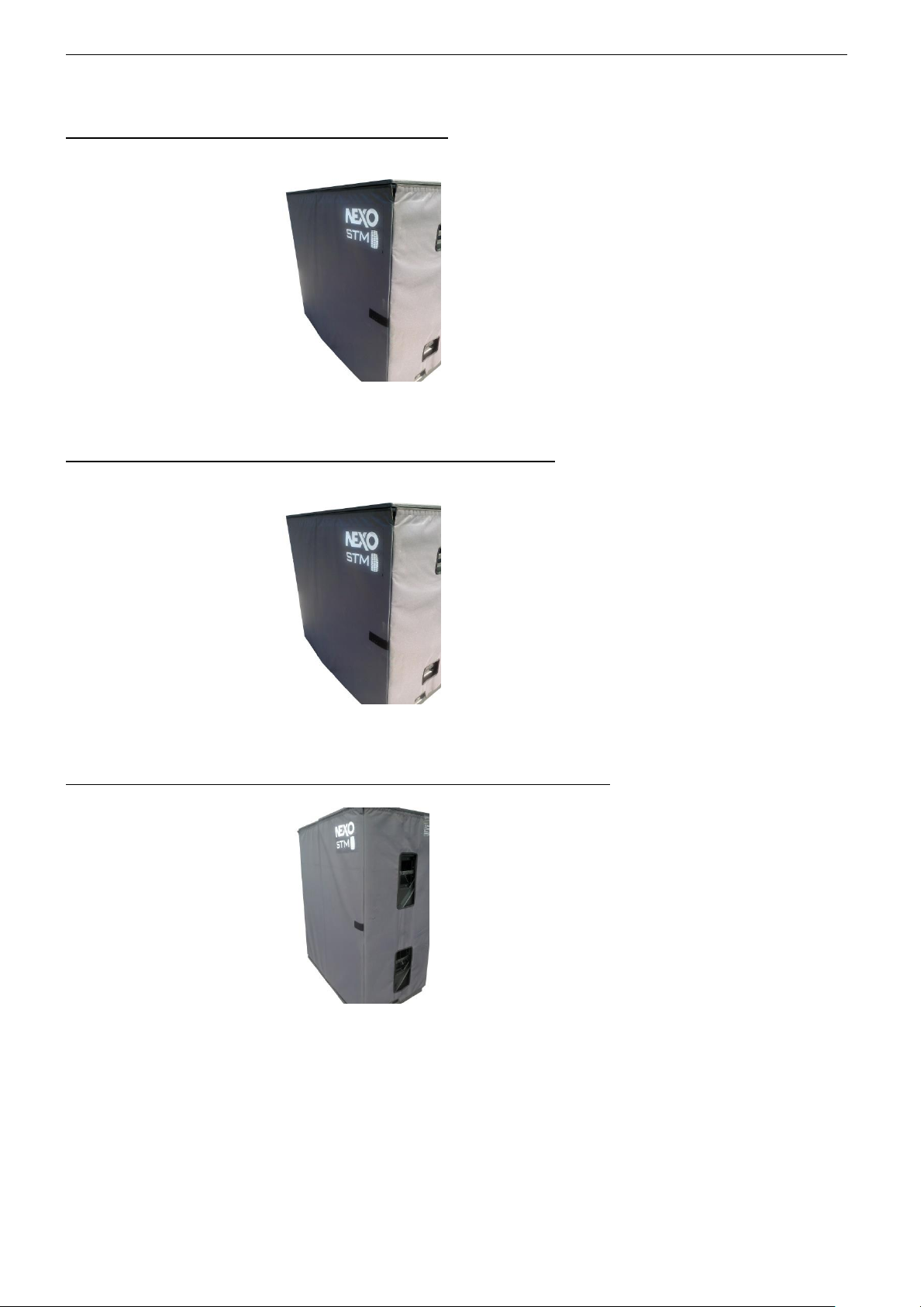
Page 60/62 STM ACCESSORIES
DCOVER04 – Lateral cover for 2xS118 on DOLLY01
Item: 1 x unit
Weight: 4 kg / 9lb
DCOVER02 – Lateral cover for 2x3xM46 or 2x3xB112 on DOLLY02
Item: 1 x unit
Weight: 6 kg / 13lb
DCOVER03 – Lateral cover for 8xM46 or 8xB112 or 4xS118 (on DOLLY02)
Item: 1 x unit
Weight: 7 kg / 15lb
Page 61
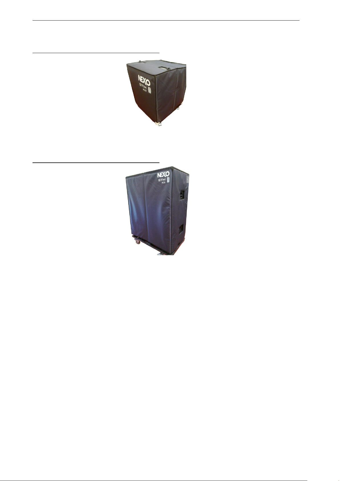
STM ACCESSORIES Page 61/62
DCOVER283 – Cover for 3xM28 (on DOLLY03)
Item: 1 x unit
Weight: 3 kg / 7lb
DCOVER283 – Cover for 3xM28 (on DOLLY03)
Item: 1 x unit
Weight: 6 kg / 13lb
Page 62

Page 62/62 USER NOTES
11 USER NOTES
France
Nexo S.A.
Parc d’activité de la Dame Jeanne
F-60128 PLAILLY
Tel: +33 3 44 99 00 70
Fax: +33 3 44 99 00 30
E-mail: [email protected]
www.nexo-sa.com
 Loading...