


STM Series
STM S118 Sub Module
STM B112 Bass Module
STM M46 Main Module
STM M28 Omni Module
Setup Manual
STM Series User Manual V1.02
Date: 2016/03/25
Page 2/62 PLEASE READ CAREFULLY BEFORE PROCEEDING
PLEASE READ CAREFULLY BEFORE PROCEEDING
BASIC PRECAUTIONS
Do not open the speaker system or attempt to disassemble the internal parts or modify them in any way.
The speaker system contains no user-serviceable parts. If it should appear to be malfunctioning or damaged,
discontinue use immediately and have it inspected by qualified NEXO service personnel.
Water exposure: Do not expose the speaker system to direct rain; do not use it near water or in wet
conditions. Do not place containers with liquid on speaker system as they might spill into openings. If any
liquid such as water seeps into the speaker system, have it inspected by qualified NEXO personnel.
SYSTEM DEPLOYMENT SAFETY RULES
Read User Manual before deployment. Before use of enclosed speaker system, please ensure
that anyone involved in system deployment understands the rigging – stacking – pole mounting
safety rules as described in the speaker system User Manual. Failure to do this exposes
people to potential injury or death.
Always consult qualified NEXO personnel if the device installation requires construction work and make sure
to observe the following precautions:
Mounting precautions
- choose mounting hardware and an installation location that can support the weight of the speaker system;
- do not use speaker system handles for suspended installation;
- do not expose speaker system to excessive dust or vibration, or extreme cold or heat to prevent possibility
of component damage;
- do not place the speaker system in an unstable position from which it might fall accidentally;
- if speaker systems uses a stand, ensure that stand specifications are adapted, and that stand height does
not exceed 1.40m/55”; never move the stand while the speaker is in position.
Connection and powering precautions
- remove all connected cables before moving the speaker system;
- turn off AC power of all power amplifier units before connecting the speaker system;
- when turning on the AC power to the audio system, always turn on the power amplifier last; when turning
the AC power off, always turn off the power amplifier first;
- when used in cold conditions, a gradual power ramp up should applied to the system on an 5 mn period to
allow the loudspeaker components to stabilize during the very first minutes of usage.
Inspect the speaker system periodically.

PLEASE READ CAREFULLY BEFORE PROCEEDING Page 3/62
SAFETY INSTRUCTIONS FOR NEXO TD CONTROLLERS
NXAMP4x1 AND NXAMP4x4 POWERED CONTROLLERS ARE CLASS 1 APPARATUS AND
MUST BE EARTHED.
THE GREEN AND YELLOW WIRE OF THE MAINS CORD MUST ALWAYS BE CONNECTED TO AN
INSTALLATION SAFETY EARTH OR GROUND. THE EARTH IS ESSENTIAL FOR PERSONAL SAFETY AS
WELL AS THE CORRECT OPERATION OF THE SYSTEM, AND IS INTERNALLY CONNECTED TO ALL
EXPOSED METAL SURFACES.
- Read these instructions.
- Keep these instructions.
- Heed all warnings.
- Follow all instructions.
- Do not use this apparatus near water.
- Clean only with dry cloth.
- Do not block any ventilation openings. Install in accordance with the manufacturer’s instructions.
- Do not install near any heat sources such as radiators, heat registers, stoves, or other apparatus (including
amplifiers) that produce heat.
- Do not defeat the safety purpose of the polarized or grounding-type plug. A polarized plug has two blades
with one wider than the other. A grounding type plug has two blades and a third grounding prong. The wide
blade and the third prong are provided for your safety. If the provided plug does not fit into your outlet,
consult an electrician for replacement of the obsolete outlet. (US market)
- Protect the power cord from being walked on or pinched particularly at plugs, convenience receptacles,
and the point where they exit from the apparatus.
- Only use attachments/accessories specified by the manufacturer.
- Unplug this apparatus during lightning storms or when unused for long periods of time.
- Refer all servicing to qualified service personnel. Servicing is required when the apparatus has been
damaged in any way, such as power-supply cord or plug is damaged, liquid has been spilled or objects
have fallen into the apparatus, the apparatus has been exposed to rain or moisture, does not operate
normally, or has been dropped.
Page 4/62 PLEASE READ CAREFULLY BEFORE PROCEEDING
HIGH SOUND PRESSURE LEVELS
Exposure to extremely high noise levels may cause permanent hearing loss. Individuals vary
considerably in susceptibility to noise-induced hearing loss but nearly everyone will lose some
hearing if exposed to sufficiently intense noise for a sufficient period of time. The U.S.
Government’s Occupational and Health Administration (OSHA) has specified the following
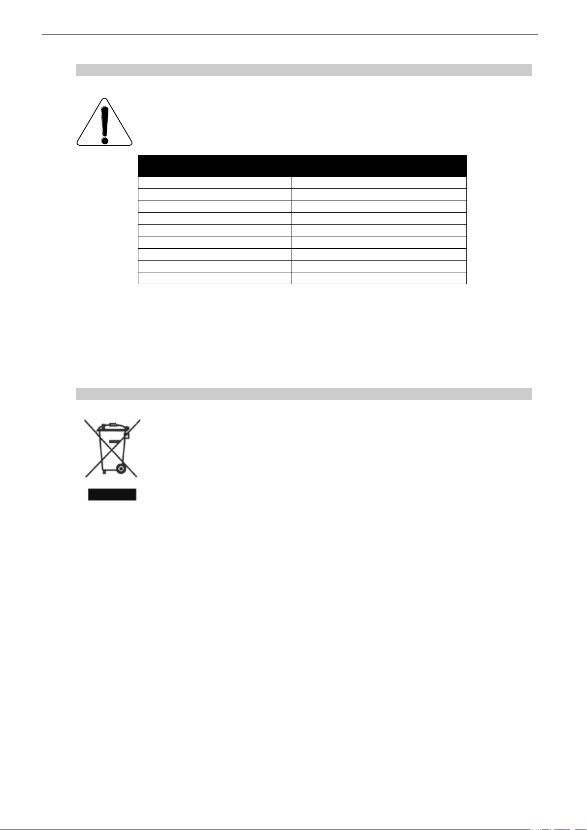
permissible noise level exposures: Sound Duration Per
Day In Hours
Sound Level dBA, Slow Response
8
90 6 92 4 95 3 97
2
100
1 ½
102 1 105 ½ 110
¼ or less
115
According to OSHA, any exposure in excess of the above permissible limits could result in some hearing loss.
Ear plugs or protectors to the ear canals or over the ears must be worn when operating this amplification system
in order to prevent permanent hearing loss, if exposure is in excess of the limits as set forth above. To ensure
against potentially dangerous exposure to high sound pressure levels, it is recommended that all persons
exposed to equipment capable of producing high sound pressure levels such as this amplification system be
protected by hearing protectors while this unit is in operation.
DISPOSAL OF OLD ELECTRICAL & ELECTRONIC EQUIPMENT
This symbol on the product or on its packaging indicates that it shall not be treated as
household waste. Instead it shall be handed over to the applicable collection point for the
recycling of electrical and electronic equipment. By ensuring this product is disposed of
correctly, you will help prevent potential negative consequence for the environment and
human health, which could otherwise be caused by inappropriate waste handling of this
product. The recycling of materials will help to conserve natural resources. For more
detailed information about recycling of this product, please contact your local city office,
your household waste disposal service or the shop where you purchased the product.

CONTENTS Page 5/62
CONTENTS
PLEASE READ CAREFULLY BEFORE PROCEEDING ........................................................ 2
CONTENTS ............................................................................................................................. 5
1 Introduction ..................................................................................................................... 7
2 STM Connectors and cabling ........................................................................................ 9
2.1 Speaker modules connection .................................................................................... 9
2.2 STM cabling ............................................................................................................ 11
3 STM and NUAR NEXO Universal Rack........................................................................ 12
3.1 NUAR Components ................................................................ ................................. 12
3.1.1 NXAMP4x4 .......................................................................................................... 12
3.1.2 DMU (Digital Metering Unit) ................................................................................. 13
3.1.3 DPU (Digital Patching Unit) .................................................................................. 13
3.1.4 Digital audio networking ....................................................................................... 14
3.1.5 Power box ............................................................................................................ 14
3.1.6 Rack ..................................................................................................................... 14
3.2 STM Setups ............................................................................................................. 14
3.2.1 NEXO STM configurations ................................................................................... 14
3.2.2 Custom STM configurations ................................................................................. 14
STM and NUAR configurations .......................................................................................... 15
4 NS-1 Simulation software ............................................................................................ 21
5 STM system deployment procedure ........................................................................... 22
5.1 SAFETY FIRST ....................................................................................................... 22
5.1.1 Flown Systems Safety ......................................................................................... 22
5.1.2 Ground Stacking Safety ....................................................................................... 23
5.1.3 Contacts ............................................................................................................... 23
5.2 General Description ................................................................................................. 24
5.2.1 STM Modules ....................................................................................................... 24
5.2.2 Rigging Components ........................................................................................... 25
5.2.3 One rigging point rigging modes .......................................................................... 26
5.2.4 Two rigging points modes .................................................................................... 27
5.3 Upper assembly ...................................................................................................... 28
5.4 Flying on a single motor with bridle ......................................................................... 29
5.5 Flying on a single motor with Variobumper .............................................................. 31
5.6 Flying on two motors and a chain lever hoist (M28 default mode) ........................... 32
5.7 Flying on two motors and kelping chain (M46 + B112 default mode) ...................... 33

Page 6/62 CONTENTS
5.8 Connecting subsequent modules and presetting angles ......................................... 35
5.9 Lower Assembly ...................................................................................................... 37
5.10 Compression and bumper angle with a single motor ............................................... 38
5.11 Compression and bumper angle with 2 motors and a chain lever hoist ................... 38
5.12 Compression and bumper angle with 2 motors and kelping chain ........................... 39
5.13 Adding M28 as a downfill for M46 ............................................................................ 40
5.14 Special case: flying with lightweight bumper ............................................................ 42
5.15 Special case: flying S118 only clusters .................................................................... 44
6 STM S118 Technical Specifications ............................................................................ 47
7 STM B112 Technical Specifications ............................................................................ 48
8 STM M46 Technical Specifications .............................................................................. 49
9 STM M28 Technical Specifications .............................................................................. 50
10 STM accessories ........................................................................................................... 51
10.1 Rigging accessories ................................................................................................. 51
10.2 Transport accessories ............................................................................................. 57
11 USER NOTES................................................................................................................. 62

INTRODUCTION Page 7/62
1 INTRODUCTION
Thank you for selecting a NEXO STM Series Modular Line Array System. This manual is intended to provide
you with necessary and useful information about your STM System, which includes the following products:
S118 is STM Sub Module. It comprises a
band-pass loaded 1x18” (46cm) 4” voice
coil Neodynium high- excursion driver. An
innovative profile for vent increases limits of
air-flow non-linearity, and allows S118 to
deliver very high SPL output under a
compact volume.
B112 is STM Bass Module. It comprises a
1x12” (46cm) 4” voice coil Neodynium highexcursion driver. B112 load is a hybrid
combination of exponential horn and vented
enclosure, which provides high efficiency
while keeping low frequency impact.
M46 is STM Main Module. It comprises
4x6.5” flat membrane drivers minimizing
diffraction along the HF path, loaded by
anti-resonance vents. HF is handled by
4x2.5” coil / 1.4” exit neodymium drivers
featuring Keton Polymere diaphragms;
these 4 units are HRWTM NEXO proprietary
waveguide loaded.
M28 is STM Omni module. It can
complement M46 as a downfill, or be flown
or stacked in columns.
It comprises 2x8’’ long excursion
neodymium LF/MF drivers, loaded by antiresonance vents, as well as 2x2.5” coil / 1.4”
exit neodymium drivers featuring Keton
Polymere diaphragms; these 2 units are
HRWTM NEXO proprietary waveguide
loaded. M28 can be configured in 90° or
120° horizontal coverage.
Page 8/62 INTRODUCTION
The NEXO Universal Amp Rack feeds 12
STM modules in any combination in groups
of 3. Comprising two NXAMP4x4 amplifiers,
2 digital input patches (DMU), 2 digital
output patches (DPU) and EtherSoundTM,
DanteTM or AES cards, the NUAR forms a
compact, powerful and scalable
amplification solution for STM systems of
any size.
STM Accessory Range. a full range of
accessories that provides safe, flexible and
simple means of transporting, protecting,
installing STM modules in touring
applications.
NS-1 simulation software assists in the
design and implementation of STM
modules. Please consult the NEXO web site
(www.NEXO.fr or www.NEXO-sa.com) for
the latest software releases.
NeMo Remote Monitoring: available for
iPad and Mac, NEXO’s NeMo Remote
Monitoring app provides remote control
over a NXAMP network from anywhere in
the venue.
Please devote your time and attention to reading this manual.
A comprehensive understanding of STM technologies, applications and specific features will help you
to operate your system at its full potential.

STM CONNECTORS AND CABLING Page 9/62
2 STM CONNECTORS AND CABLING
2.1 Speaker modules connection
Connection system has been designed so that it is simple and mistake proof. STM modules connector panels
feature robust chassis metal connectors Speakon NL4 and/or NL8.
A wiring diagram is printed on the connection panel located on the back of each cabinet.
Table below gives STM general wiring assignment.
Module – Channel
NL4 / NL8 wiring
S118 - VLF
1-/1+
B112 - LF
2-/2+
M46 - MF
3-/3+
M46 - HF
4-/4+
M28 – LF/MF
1-/1+ (NL4 only)
M28 - HF
2-/2+ (NL4 only)
STM S118 connector panel
Speakon
Connecting
1(-)
S118 (-)
1(+)
S118 (+)
2(-)
To B112 (-)
2(+)
To B112 (+)
STM S118 is connected with Speakon
NL4FC plugs (not supplied). The 4 pins of the
2 Speakon sockets identified in / out are
connected in parallel within the enclosure.
Either connector can be used to connect
amplifier or to link to an additional S118 Sub
Module or to a B112 Bass Module. Therefore,
a single 4-conductor cable can connect two
amplifier channels up to 3xS118s and
3xB112s.
S118
WARNING
Operate only with NEXOTD Controller.
PROFESSIONALEQUIPMENT!
Please refer t o UserManual for
WorkingLoad Limits(WLL)
andRiggingInstructions.
WARNING
Disregard of RiggingInstructions
and/orWLL maydamage equipment
andri skpersonal injury or death.
WARNING
Exposure to high soundpressurel evels
maycausea permanent hearingloss.
Referto User Manual.
1 SUB
2 L F
MADE IN FRANCE
1 SUB
2 L F

Page 10/62 STM CONNECTORS AND CABLING
STM B112 connector panel
Speakon
Connecting
1(-)
To S118 (-)
1(+)
To S118 (+)
2(-)
B112 (-)
2(+)
B112 (+)
STM B112 is connected with Speakon
NL4FC plugs (not supplied). The 4 pins of the
2 Speakon sockets identified in / out are
connected in parallel within the enclosure.
Either connector can be used to connect
amplifier or to link to an additional B112 Bass
Module or to a S118 Sub Module. Therefore,
a single 4-conductor cable can connect two
amplifier channels to up to 3xS118s and
3xB112s.
STM M46 connector panel
Speakon
Connecting
1(-)
To S118 (-)
1(+)
To S118 (+)
2(-)
To B112 (-)
2(+)
To B112 (+)
3(-)
M46 – MF (-)
3(+)
M46 – MF (+)
4(-)
M46 – HF (-)
4(+)
M46 – HF (+)
STM M46 is connected with Speakon NL8FC
plugs (not supplied). The 8 pins of the 2
Speakon sockets identified in / out are
connected in parallel within the enclosure.
Either connector can be used to connect
amplifier or to link to an additional M46 main
Module. Additionally, STM M46 panel
features 1 NL4 connector allowing local link
to S118 or B112.
Therefore, a single 8-conductor cable can
connect 4 amplifier channels to up to
3xS118s, 3xB112s and 3 M46s.
B112
WARNING
Operateonly wit h NEXOTD Controller.
PROFESSIONAL EQUIPMENT!
Please refer t oU serManual for
WorkingLoad Limits(WLL)
andRiggingInstructions.
WARNING
Disregardof RiggingInstructions
and/orWLLmay damageequipment
andrisk personalinjur y or death.
WARNING
Exposuret o highsound pressure levels
maycausea permanent hearingloss.
Referto User Manual.
1 SU B
2 L F
MADE IN FRANCE
1 SU B
2 L F
M46
1 SUB
2 L F
3 MF
4 H F
1 SUB
2 L F
3 MF
4 H F
WARNING
Operate only with NEXOTD Controller.
PROFESSIONALEQUIPMENT!
Pleaserefer t o UserManual for
WorkingLoad Limits (WLL)
andRiggingInstructions.
WARNING
Disregardof RiggingInstructions
and/orWLL maydamageequipment
andri skpersonali njury or death.
WARNING
Exposuret o high soundpressurelevels
maycausea permanent hearingl oss.
Referto User Manual.
1 SUB
2 L F
MADE IN FRANCE
STM CONNECTORS AND CABLING Page 11/62
STM M28 connector panel
Speakon
Connecting
1(-)
M28 - LF (-)
1(+)
M28 - LF (+)
2(-)
M28 - HF (-)
2(+)
M28 - HF +)
STM M28 is connected with Speakon NL4FC
plugs (not supplied). The 4 pins of the 2
Speakon sockets identified in / out are
connected in parallel within the enclosure.
Either connector can be used to connect
amplifier or to link to an additional M28
Module.
2.2 STM cabling
STM cabling standard is 4x4mm2/AWG#10 (NL4) or 8x4mm2/AWG#10 (NL8).
Maximum cable run is 60 meters / 200 feet
IMPORTANT
Long speaker cables induce capacitive effects – up to hundreds of pF depending on the
quality of the cable - with a low-pass effect on high frequencies. If long speaker cables must
be used, ensure that they do not remain coiled while in use.
M28
SERIALNUMBER
MADE in FRANCE
1 LF
2 H F

Page 12/62 STM AND NUAR NEXO UNIVERSAL RACK
3 STM AND NUAR NEXO UNIVERSAL RACK
The NEXO Universal Amp Rack (NUAR) provides NEXO users with a scalable, ‘plug & play’, amplified
audio distribution solution of unrivalled power and flexibility. Systems of any size can be configured
easily using channel by channel preset selection of any NEXO cabinet, and digital output patching.
The NUAR rack comprises a pair of NEXO NXAMP4X4 amplifiers, twin DMU digital input metering devices, a
pair of DPU digital output patching devices and a choice of 110V, 220V or dual-voltage mains distribution boxes
providing power to all the components in the rack.
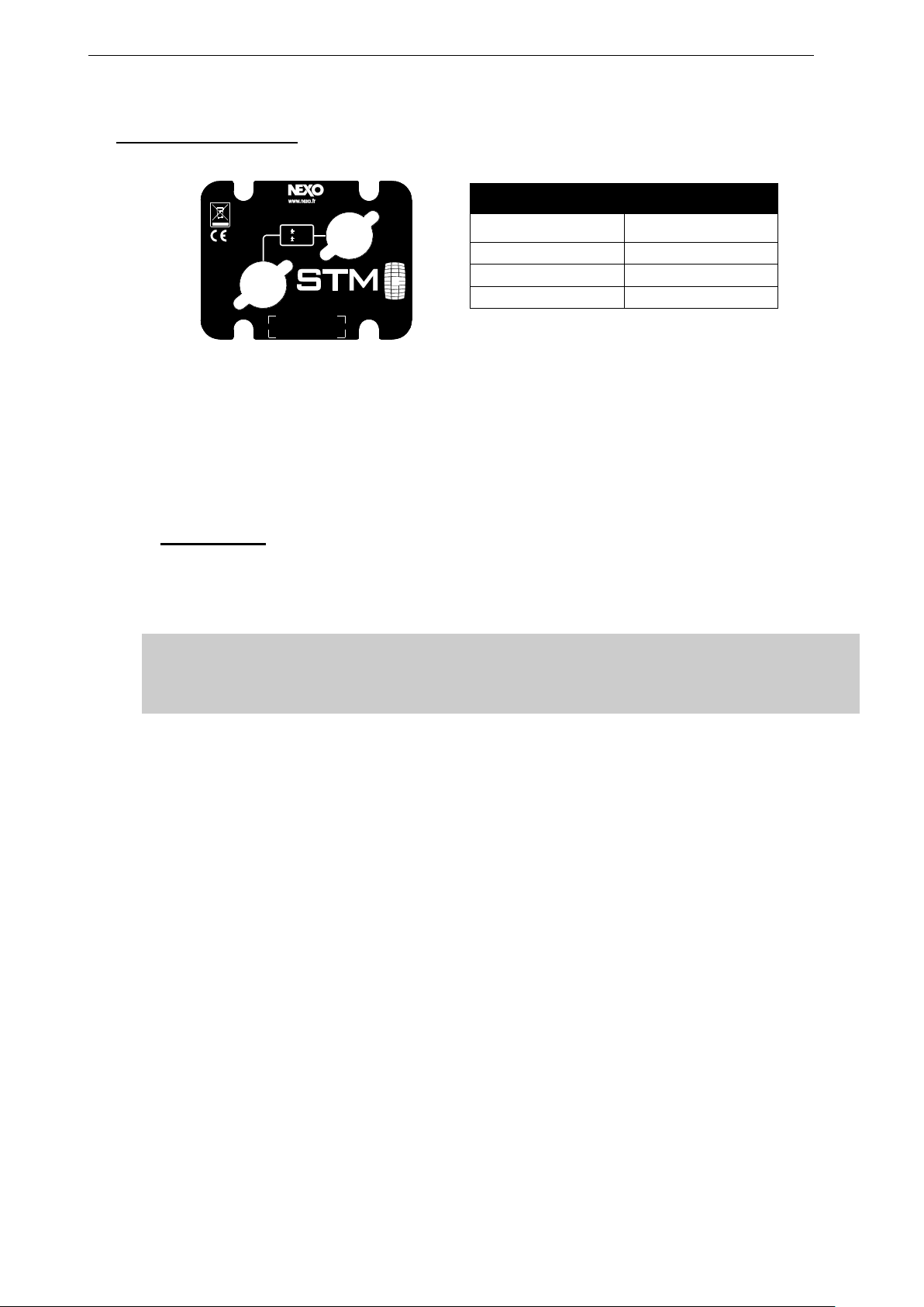
System configuration is simple, using either ESMonitor the new NEXO NeMo iPad® app. NEXO cabinet presets
are selected on a channel by channel basis, with selected cabinet names displayed by the DPU for easy output
patching.
Digital input metering is provided by the DMU, clearly indicating the presence and status of input signals,
including network inputs.
An entirely new library of presets for every single cabinet in the NEXO range delivers linear phase across any
system, making it possible to mix and match NEXO cabinets.
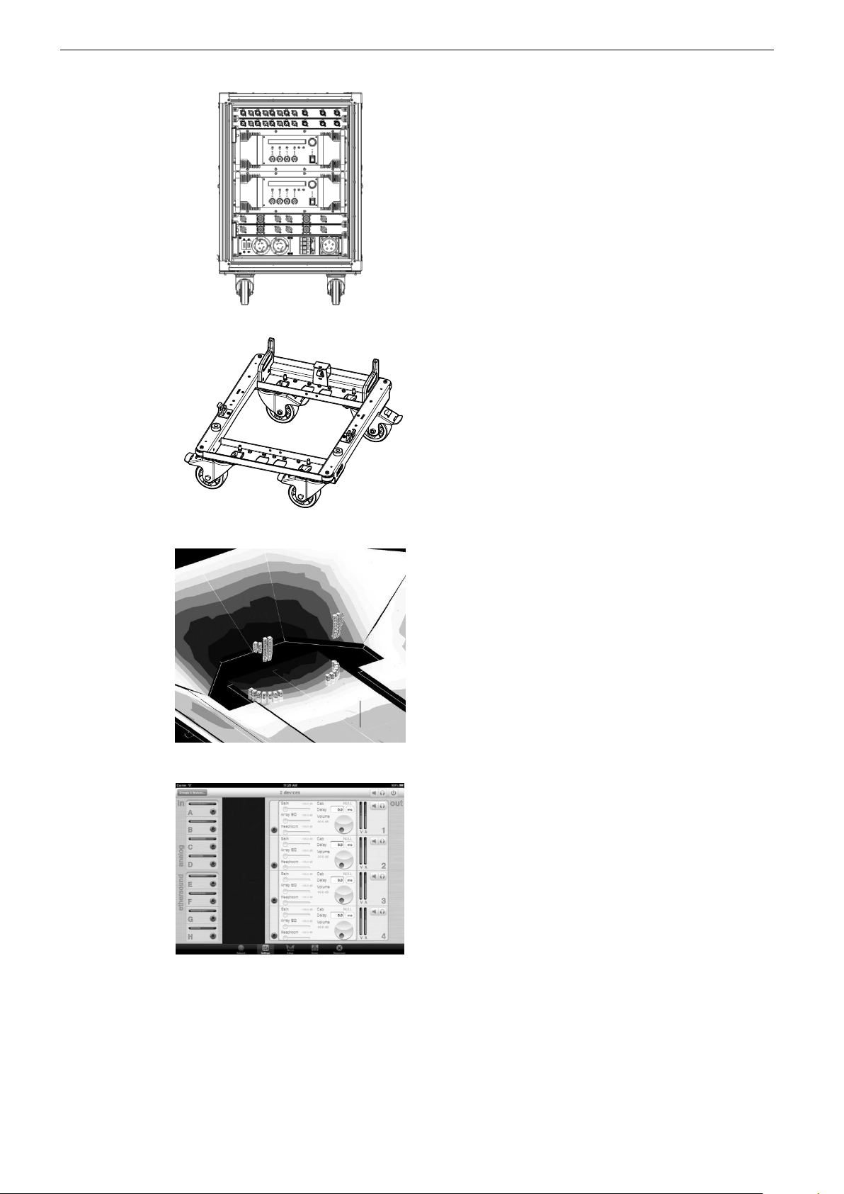
Increased efficiency and versatility is inherent in NUAR’s mechanical design. The 14U chassis is suspended
within a robust rack case, featuring two sliding doors and an integrated rigging system. This enables up to 3
racks to be flown using an optional bumper and the easy attaching/detaching of a wheel board.
Each NUAR is fully configured and tested at NEXO to provide a truly versatile and tailored ‘Plug & Play’
amplification solution.
3.1 NUAR Components
For a complete description of these units, please refer to NEXO User Manuals.
3.1.1 NXAMP4x4
Among the most powerful amplifiers in the industry, the NXAMP4X4 integrates command, control,
amplification and protection functions within a relatively light weight and space-saving 4U rack.
By combining real-time monitoring of temperature, voltage and current with powerful dual-DSP control, the
NXAMP4X4 achieves exceptional performance with a high degree of protection for both amplifier and power
supply, while simultaneously offering all control parameters required for the speakers.

STM AND NUAR NEXO UNIVERSAL RACK Page 13/62
The latest firmware load enables channel by channel preset selection for any speaker in the NEXO range. The
result of a 2-year development program, all presets have been revised using FIR filtering to ensure linear phase
across any combination of NEXO cabinets, making it possible to mix and match cabinets in a single, coherent
system.
EtherSound™ and Dante™ digital networking cards can be installed. Latest generation 24-bit audio converters
provide enhanced dynamic range with low latency (500us analogue input to output in ‘flat’ mode), eliminating
the need for external A/D conversion.
Improved power efficiency and decreased heat generation comes courtesy of four separate Switch Mode
Power Supplies, which ensure high power capacity with low load drive. NEXO amplification technology delivers
maximum efficiency in drive performance and power, while providing the audio quality of traditional class AB
amplifiers with the heat dissipation of class D amplifiers. This results in a 50% reduction in power consumption,
contributing to outstanding sound quality. Converters operate synchronized in the opposite phase, thus
cancelling noise.
The NXAMP4X4 delivers 4 x 4000W into 2 Ohm loads, and is available in 110V, 220V and dual voltage
versions.
3.1.2 DMU (Digital Metering Unit)
DMU is the ultimate tool for the easy monitoring of any activity on the NXAMP audio inputs. The DMU is totally
driven by the host NXAMP, with signal and power supply coming from the NXAMP’s GPIO port. Front panel
features include 4 analogue XLR inputs plus links, three RJ45 ports for digital audio networking and LED VU
meters. Particular care has been taken to ensure minimum insertion losses in the analogue audio signal.
Key Features:
• Intelligent input patch panel offering digital communication with NXAMPs.
• Provides input level meters on all analogue and network inputs.
• Fully passive design on the audio and network paths.
• Powered through the host NXAMP, no need for mains supply.
3.1.3 DPU (Digital Patching Unit)
The DPU is designed to optimise use of the NXAMP’s channel by channel preset selection by automatically
routing its outputs to any of 6 output connectors on the DPU front panel. Cabinet names and bridging status
are displayed alongside each output, making it easy to wire the system. Security is assured by fully redundant
power supplies and dual switching. When connecting DPU to the NXAMP, a routine first checks that the power
from the amplifier is coming from the correct channel. If communication is lost with the NXAMP, the DPU retains
its configuration until contact is resumed.
Key Features
• Intelligent input patch panel offering digital communication with NXAMPs.
• Provides input level meters on all analogue and network inputs.
• Fully passive design on the audio and network paths.
• Powered through the host NXAMP, no need for mains supply.

Page 14/62 STM AND NUAR NEXO UNIVERSAL RACK
3.1.4 Digital audio networking
NUAR racks can be pre-configured with EtherSound™ or Dante™ digital audio networking capabilities,
enabling users to monitor and controlthe NXAMPs.
NXES104 EtherSoundTM Network Card
Key Features
• Extracts 4 audio streams (24 bits / 48 KHz) among the 2 x 64 channels of a ES100 EthersoundTM stream.
• IN and OUT port for simple daisy chain without any need for an external switch.
• 3rd Ethernet port for remote control of the whole network from any NXES104 card and ASIO streaming.
NXDT104 DanteTM Network Card
Key Features
• Receives 4 audio streams (24 bits / 48 KHz) in DanteTM format.
• Unique 3-port design can be used:
- Has an integrated 3 port gigabit switch
- Has two Dante™ redundant port plus an optional 3rd port for additional remote control
• Direct connection to PC using the ASIO format.
3.1.5 Power box
NUAR can be configured with a choice of 110V, 220V or dual-voltage power distribution boxes, allowing the
user to achieve the optimum balance of versatility and cost efficiency.
Where necessary, the power distribution boxes feature color-coding to assist power balancing when using three
phase supplies. The color-coding is also labelled on the rack case.
3.1.6 Rack
The 14U chassis is suspended within a rack case, featuring two sliding doors and an integrated rigging system.
Up to 3 racks can be flown using an optional bumper.
3.2 STM Setups
STM setups are available on NXAMP4x4 in “System Configuration” Menu in the STM section.
These setups are fixed in software and updated regularly: please consult the NEXO web site (www.nexo.fr) for
the latest software releases.
Load 4.0+ Key Features
Set up selection per channel
Linear phase on all set-ups
All NEXO systems compatible 20Hz-20kHz
Selectable crossover points for subs
8 fully parametric EQs per channel
3.2.1 NEXO STM configurations
These are NEXO recommended STM for proper STM operation. Please check STM setup list enclosed with
NXAMP loads (available at www.nexo-sa.com)
3.2.2 Custom STM configurations
NXAMP4x4 Load 4.0+ (“setup per channel”) allows re-configuring NEXO speaker setups in any combination
on the 4 channels when going into the Custom Setup menu.

STM AND NUAR NEXO UNIVERSAL RACK Page 15/62
STM and NUAR configurations
A NUAR rack can feed 12 modules of STM – whatever they are – provided they are paralleled by 3.
Active Mode
3xSTM S118
2 channels of NXAMP4x4 in bridge stereo mode
3xSTM B112
2 channels of NXAMP4x4 in bridge stereo mode
3xSTM M46
2 channels of NXAMP4x4 in 4 channels mode
3xSTM M28
2 channels of NXAMP4x4 in 4 channels mode
IMPORTANT
- Paralleling less than 3 STM modules on NXAMP4x4 channels does not change power delivered
to each module
- Exceeding 3 paralleled STM modules on NXAMP4x4 channels will lead to a power drop of at
least 50% in each module.
12xS118 and 1 NUAR

Page 16/62 STM AND NUAR NEXO UNIVERSAL RACK
12xB112 and 1 NUAR
12xM46 and 1 NUAR

STM AND NUAR NEXO UNIVERSAL RACK Page 17/62
12xM28 and 1 NUAR
6xB112 and 6xM46

Page 18/62 STM AND NUAR NEXO UNIVERSAL RACK
6xS118 and 6xB112
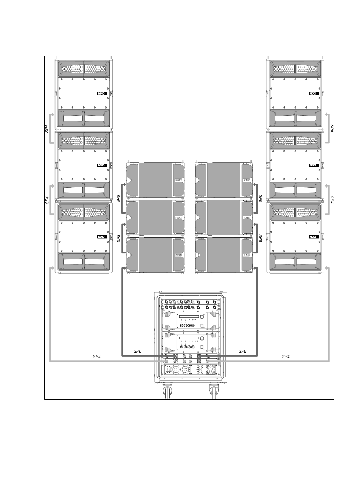
STM AND NUAR NEXO UNIVERSAL RACK Page 19/62
6xS118 and 6xM46
 Loading...