

Nexo RS18, RS15 User Manual

DP5235-01-CM
RS Series
RS15 & RS18 Subwoofers
System manual

CONTENTS
Page 2 / 76 System Manual RS Series
CONTENTS
PLEASE READ CAREFULLY BEFORE PROCEEDING .................................................................................. 5
1 INTRODUCTION ......................................................................................................................................... 7
2 RS GENERAL SET-UP INSTRUCTIONS ................................................................................................. 8
2.1 RS15 AND RS18 CONNECTIONS .............................................................................................................................8
2.1.1 RS15 connectors................................................................................................................................................................... 8
2.1.2 RS18 connectors................................................................................................................................................................... 8
2.1.3 Configuring connector and owner plates ................................................................................................................. 9
2.2 CABLING ................................................................................................................................................................... 10
2.3 RS15 AND RS18 RECOMMENDED AMPLIFICATION .......................................................................................... 10
2.4 RS15 AND RS18 SETUPS ON NEXO TD CONTROLLERS ................................................................................. 10
3 CONNECTION DIAGRAMS ..................................................................................................................... 11
3.1 RS15 / NXAMP4X1MK2 (BRIDGE STEREO) ................................................................................................... 11
3.2 RS18 / NXAMP4X1MK2 (BRIDGE STEREO) ................................................................................................... 11
3.3 RS15 / NXAMP4X2MK2 (4 CHANNELS MODE) .............................................................................................. 12
3.4 RS15 / NXAMP4X4MK2 (4 CHANNELS MODE) .............................................................................................. 13
3.5 RS18 / NXAMP4X4MK2 (4 CHANNELS MODE) .............................................................................................. 14
4 NS-1 SIMULATION SOFTWARE .......................................................................................................... 15
5 RS HARDWARE SETUP PROCEDURE ................................................................................................ 16
5.1 SAFETY FIRST ........................................................................................................................................................... 16
5.1.1 Flown systems safety ....................................................................................................................................................... 16
5.1.2 Ground stacking safety ................................................................................................................................................... 17
5.1.3 Contacts ................................................................................................................................................................................. 17
5.2 RS15 GENERAL INSTRUCTIONS ........................................................................................................................... 18
5.2.1 RS15 “Left” and “Right” .................................................................................................................................................. 18
5.2.2 RS15 handles ....................................................................................................................................................................... 19
5.2.3 RS15 Flying Plates with handles (touring applications) ................................................................................ 19
5.2.4 RS15 Wheels ........................................................................................................................................................................ 20
5.2.5 RS15 Dolly ............................................................................................................................................................................. 21
5.3 RS18 GENERAL INSTRUCTIONS ........................................................................................................................... 22
5.3.1 Mounting Rigging Plate ................................................................................................................................................. 22
5.3.2 RS18 Dolly ............................................................................................................................................................................. 26
5.3.3 RS18 Wheel Board ............................................................................................................................................................ 27
5.4 ACCESSORIES ........................................................................................................................................................... 28
5.5 WARNINGS ON RS15 AND RS18 ACCESSORIES ................................................................................................. 29
5.6 FLYING RS15 ........................................................................................................................................................... 30
5.7 FLYING RS18 ........................................................................................................................................................... 34
5.8 TESTING AND MAINTENANCE OF THE SYSTEM .................................................................................................. 38
6 GENERAL GUIDELINES FOR SUBWOOFER DESIGN...................................................................... 39
6.1 LOW FREQUENCY ISSUES ....................................................................................................................................... 39
6.2 GRADIENT SUBWOOFERS BENEFITS .................................................................................................................... 39
6.3 MONOPHONIC DESIGN ........................................................................................................................................... 40
6.4 STEREO DESIGN....................................................................................................................................................... 40
7 RAY SUB IMPLEMENTATION .............................................................................................................. 42
7.1 OMNIDIRECTIONAL MODE ..................................................................................................................................... 42
7.1.1 Single RS15 and RS18 ...................................................................................................................................................... 42
7.1.2 RS15 and RS18s arrays ................................................................................................................................................... 42
7.2 DIRECTIONAL MODE .............................................................................................................................................. 43
7.2.1 Single RS15 or RS18 ......................................................................................................................................................... 43
7.2.2 RS15s pair ............................................................................................................................................................................. 44
7.2.3 RS18s pair ............................................................................................................................................................................. 45
7.2.4 RS15s and RS18s arrays ................................................................................................................................................. 46

CONTENTS
System Manual RS Series Page 3 / 76
7.3 STEERED RS15S ARRAYS ...................................................................................................................................... 47
7.3.1 Steering technique ............................................................................................................................................................ 47
7.3.2 Delay values implementation ...................................................................................................................................... 47
7.3.3 Coverage result ................................................................................................................................................................... 48
7.4 STEERED RS18S ARRAYS ...................................................................................................................................... 49
7.4.1 Steering technique ............................................................................................................................................................ 49
7.4.2 Delay values implementation ...................................................................................................................................... 49
7.4.3 Coverage result ................................................................................................................................................................... 50
7.5 ALIGNING RS WITH MAIN SYSTEM ....................................................................................................................... 51
7.5.1 Alignment with distance measurement .................................................................................................................. 51
7.5.2 Alignment with phase measurement ....................................................................................................................... 52
7.5.3 Driving RS from the AUX send ..................................................................................................................................... 52
7.6 RECOMMENDED INSTALLATION TOOLS AND EQUIPMENT ................................................................................ 52
7.7 RS SYSTEM CHECK LIST......................................................................................................................................... 53
8 TECHNICAL SPECIFICATIONS ............................................................................................................. 54
8.1 RS15 ......................................................................................................................................................................... 54
8.1.1 System specifications ....................................................................................................................................................... 54
8.1.2 Dimensions (mm/inches) ............................................................................................................................................... 55
8.1.3 Frequency response and impedance ........................................................................................................................ 55
8.1.4 Polar plots ............................................................................................................................................................................. 56
8.2 RS18 ......................................................................................................................................................................... 59
8.2.1 System specifications ....................................................................................................................................................... 59
8.2.2 Dimensions (mm/inches) ............................................................................................................................................... 60
8.3 RS15 AND RS18 ACCESSORIES ............................................................................................................................ 61
8.3.1 RST-BUMPER15 ................................................................................................................................................................. 61
8.3.2 RST-FPLATES15 ................................................................................................................................................................. 62
8.3.3 RST-HANDLES15 ............................................................................................................................................................... 63
8.3.4 RST-WHEELS15 ................................................................................................................................................................. 64
8.3.5 RST-DOLLY15 ...................................................................................................................................................................... 65
8.3.6 RSI-INSP15 ........................................................................................................................................................................... 66
8.3.7 RST-BUMPER18 ................................................................................................................................................................. 67
8.3.8 RST-FPLATES18 ................................................................................................................................................................. 68
8.3.9 RST-HANDLES18 ............................................................................................................................................................... 69
8.3.10 RST-WB18.................................................................................................................................................................. 70
8.3.11 RST-DOLLY18 ........................................................................................................................................................... 71
8.3.12 VXT-BL820................................................................................................................................................................. 72
9 RS15 & RS18 MODULES & ACCESSORIES LIST .............................................................................. 73
10 USER NOTES ............................................................................................................................................. 75

PLEASE READ CAREFULLY BEFORE PROCEEDING
Page 4 / 76 System Manual RS Series
Going one step further in low frequency control: Ray Sub Technology
Radiation control of low frequencies is hard to achieve due to wavelength being larger than cabinet size. Consequently, most of
current subwoofers available on the audio-professional market are omnidirectional.
Drawbacks in using omnidirectional subwoofers are known by experienced engineers:
• Low Frequency sound pressure level is typically higher on stage than over the audience; high-pass filters are
mandatory in almost all microphones inputs to avoid feedback from the microphones to the subwoofers. Moreover,
gain from microphone to speakers is highly limited due to that feedback (reinforcing a double-bass can be an enormous
challenge)
• Indoor environments typically have much higher reverberation time in the Low Frequency range than in the mid and
high Frequencies. This characteristic is emphasized by the omnidirectional pattern of conventional subwoofers (all
sound engineers experienced kick drum lasting forever
• Many outdoor shows occur nearby residential areas where noise constraints are very restrictive; in such cases, low
frequencies levels over the audience have to be limited so that environment criteria are fulfilled (possibly leading to
unacceptable wideband limitations)
Gradient subwoofers provide an elegant solution to the above issues, based on a technology that is a simple transposition to
sound sources of what has been applied for decades in microphones: radiated field derives from pressure differences generated
from two (or more) sources:
• Rear radiation is lowered by more than 12 dB, which benefits to stage as well as to neighbours
• Direct to reverberant ratio is increased by nearly 6 dB in the low frequency range (which potentially gives back a kick
drum its original “punch”)
However, there are efficiency limitations: gain in lower bandwidth is reduced when sources become too close in relation to
wavelength, and pattern control is limited in upper bandwidth when both sources interfere destructively in the radiation axis.
Operating bandwidth were efficiency combines with pattern control is around 2 octaves.
Poor correlation between cabinet design and targeted specifications leads to two (and eventually more) drivers in directional
mode producing less energy than one driver in omnidirectional mode, which is not acceptable for simple practical aspects such
as weight and volume.
NEXO released its first gradient subwoofer, the CD12, which has been complemented since then by CD18, GEO SUB and
RS15. These have been quickly adopted worldwide as standards and are considered today as state-of-the-art subwoofers. This
success is a consequence of proper cabinet design and optimized definition of phase relations through sophisticated DSP
algorithms leading to high directional control and SPL output.
With RAY SUB patented technology, NEXO is again moving one step forward. RAY SUB technology is about optimizing
positioning and phase relationship of radiating surfaces in vented enclosures, so that acoustic distance from rear to front sections
always increases as frequency decreases; consequently, rear and front section always sum up efficiently – typically 5 dB gain
from rear section in the forward direction – and cancel in the rearward direction.
Used as a single cabinet, RAY SUB Technology allows the same cabinet to be configured for any polar pattern, omnidirectional
as a standard direct radiating subwoofer when speakers are facing the audience, or highly directional when cabinet is rotated
speakers sideways or upwards.
Used in arrays, RAY SUB subwoofers can be set back to back, front to front, in vertical columns, and beam-steered upwards or
downwards provided column length is sufficient.
NEXO RAY SUB technology brings a never achieved low frequency directional control to the sound reinforcement industry,
raising one more time NEXO standards.

PLEASE READ CAREFULLY BEFORE PROCEEDING
System Manual RS Series Page 5 / 76
PLEASE READ CAREFULLY BEFORE PROCEEDING
BASIC PRECAUTIONS
Do not open the speaker system or attempt to disassemble the internal parts or modify them in any way. The speaker system
contains no user-serviceable parts. If it should appear to be malfunctioning or damaged, discontinue use immediately and have
it inspected by qualified NEXO service personnel.
Water exposure: Do not expose the speaker system to direct rain, do not use it near water or in wet conditions. Do not place
containers with liquid on speaker system as they might spill into openings. If any liquid such as water seeps into the speaker
system, have it inspected by qualified NEXO personnel.
Sun exposure: Do not expose the speaker system to direct sun.
Operating temperature with temperate climate: 0°C to +40°C (-20°C to +60°C for storage).
SYSTEM DEPLOYMENT SAFETY RULES
Read User Manual before deployment. Before use of enclosed speaker system, please ensure that anyone
involved in system deployment understands the rigging – stacking – pole mounting safety rules as described
in the speaker system User Manual. Failure to do this exposes people to potential injury or death.
Please check the web site nexo-sa.com for the latest update.
Always consult qualified NEXO personnel if the device installation requires construction work and make sure to observe the
following precautions:
Mounting precautions
- choose mounting hardware and an installation location that can support 4 times the weight of the speaker system;
- do not use speaker system handles for suspended installation;
- do not expose speaker system to excessive dust or vibration, or extreme cold or heat to prevent possibility of component
damage;
- do not place the speaker system in an unstable position from which it might fall accidentally;
- if speaker systems use a stand, ensure that stand specifications are adapted, and that stand height does not exceed
1.40m/55”; never move the stand while the speaker is in position.
- in case of wind greater than 8 on Beaufort scale (72km/h – 45mph), a touring system has to be landed or an additional
securing has to be implemented.
- for fixed installations, wind loading has to be taken into account in accordance to the national standards.
Connection and powering precautions
- remove all connected cables before moving the speaker system;
- turn off AC power of all power amplifier units before connecting the speaker system;
- when turning on the AC power to the audio system, always turn on the power amplifier last; when turning the AC power off,
always turn off the power amplifier first;
- when used in cold conditions, a gradual power ramp up should be applied to the system on a 5 mn period to allow the
loudspeaker components to stabilize during the very first minutes of usage.
Inspect the speaker system periodically.

PLEASE READ CAREFULLY BEFORE PROCEEDING
Page 6 / 76 System Manual RS Series
HIGH SOUND PRESSURE LEVELS
Exposure to extremely high noise levels may cause permanent hearing loss. Individuals vary considerably
in susceptibility to noise-induced hearing loss but nearly everyone will lose some hearing if exposed to
sufficiently intense noise for a sufficient period of time. The U.S. Government’s Occupational and Health
Administration (OSHA) has specified the following permissible noise level exposures: Sound Duration Per
Day In Hours
Sound Level dBA, Slow Response
8
90 6 92 4 95
3
97
2
100
1 ½
102 1 105 ½ 110
¼ or less
115
According to OSHA, any exposure in excess of the above permissible limits could result in some hearing loss. Ear plugs or
protectors to the ear canals or over the ears must be worn when operating this amplification system in order to prevent
permanent hearing loss, if exposure is in excess of the limits as set forth above. To ensure against potentially dangerous
exposure to high sound pressure levels, it is recommended that all persons exposed to equipment capable of producing high
sound pressure levels such as this amplification system be protected by hearing protectors while this unit is in operation.
DISPOSAL OF OLD ELECTRICAL & ELECTRONIC EQUIPMENT
This symbol on the product or on its packaging indicates that it shall not be treated as household waste.
Instead it shall be handed over to the applicable collection point for the recycling of electrical and electronic
equipment. By ensuring this product is disposed of correctly, you will help prevent potential negative
consequence for the environment and human health, which could otherwise be caused by inappropriate
waste handling of this product. The recycling of materials will help to conserve natural resources. For more
detailed information about recycling of this product, please contact your local city office, your household
waste disposal service or the shop where you purchased the product.
INTRODUCTION
System Manual RS Series Page 7 / 76
1 INTRODUCTION
Thank you for selecting a NEXO RS Series Subwoofer.
This manual is intended to provide you with necessary and useful information about your RS System, which includes the
following products:
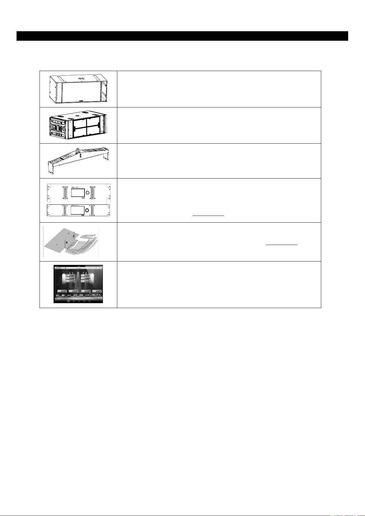
• RS15 comprises two 15” (38cm) long excursion Neodymium direct
radiating drivers mounted in a dual volume vented enclosure with
aerodynamic profiled vents.
• RS18 comprises 2x18’’ (46cm) long excursion Neodymium direct
radiating drivers mounted in a dual volume vented enclosure with
aerodynamic profiled vents.
• A full range of accessories that provides safe, flexible and simple means
of transporting and installing RS subwoofers in fixed installation as well
as in touring applications.
• RS15 and RS18 are controlled, powered and monitored by NEXO
TDcontrollers. For a complete description of these controllers, please
refer to User Manuals. NEXO TDcontrollers DSP algorithms and
parameters are fixed in software and updated regularly. Please consult
the NEXO web site (nexo-sa.com) for the latest software releases.
• NS-1 simulation software assists in the design and implementation of RS
subwoofers. Please consult the NEXO web site (nexo-sa.com) for the
latest software releases.
• Available for Mac, iPad and iPhone, NEXO NeMo provides full remote
control over a digital audio network from anywhere in the venue, thanks
to an intuitive and graphically attractive user interface. NeMo is available
on Apple App Store.
Please devote your time and attention to reading this manual. A comprehensive understanding of RS subwoofers specific
features will help you to operate your system at its full potential.
RS GENERAL SET-UP INSTRUCTIONS
Page 8 / 76 System Manual RS Series
2 RS GENERAL SET-UP INSTRUCTIONS
2.1 RS15 and RS18 connections
RS15 and RS18 are connected with Speakon NL4FC plugs (not supplied). A wiring diagram is printed on the connection panel
located on the back of each cabinet. The 4 pins of the Speakon sockets identified in / out are connected in parallel within the
enclosure.
Either connector can be used to connect amplifier or to link to an additional RS cabinet.
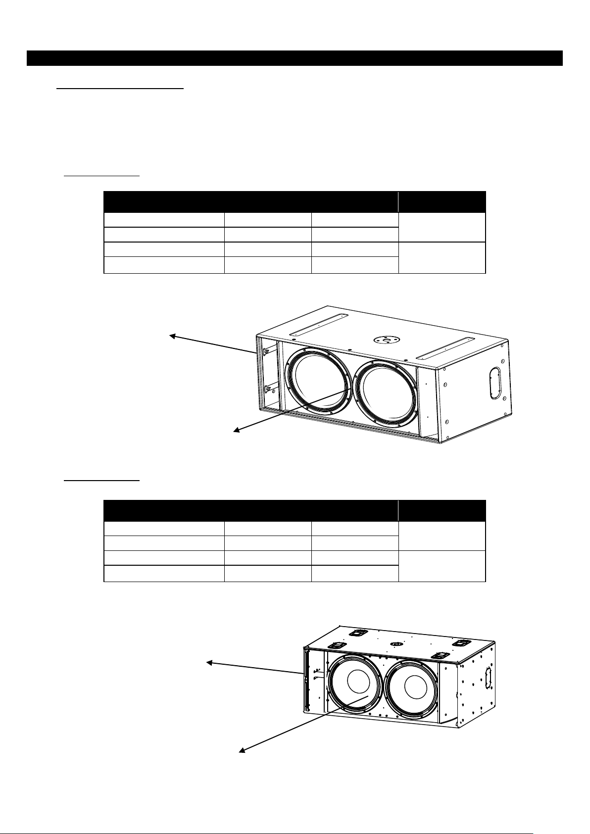
2.1.1 RS15 connectors
2.1.2 RS18 connectors
Speakon Connector
Omni Mode
Directional Mode
Comment
1(-)
Right driver (-)
Rear driver (-)
Driver next to
connector panel
1(+)
Right driver (+)
Rear driver (+)
2(-)
Left driver (-)
Front driver (-)
Driver opposite to
connector panel
2(+)
Left driver (+)
Front driver (+)
Speakon Connector
Omni Mode
Directional Mode
Comment
1(-)
Right driver (-)
Rear driver (-)
Driver next to
connector panel
1(+)
Right driver (+)
Rear driver (+)
2(-)
Left driver (-)
Front driver (-)
Driver opposite to
connector panel
2(+)
Left driver (+)
Front driver (+)
LEFT
(FRONT)
2-/2+
RIGHT
(REAR)
1-/1+
OMNI
MODE
DIRECTIONAL
MODE
OMNI
MODE
DIRECTIONAL
MODE
RS GENERAL SET-UP INSTRUCTIONS
System Manual RS Series Page 9 / 76
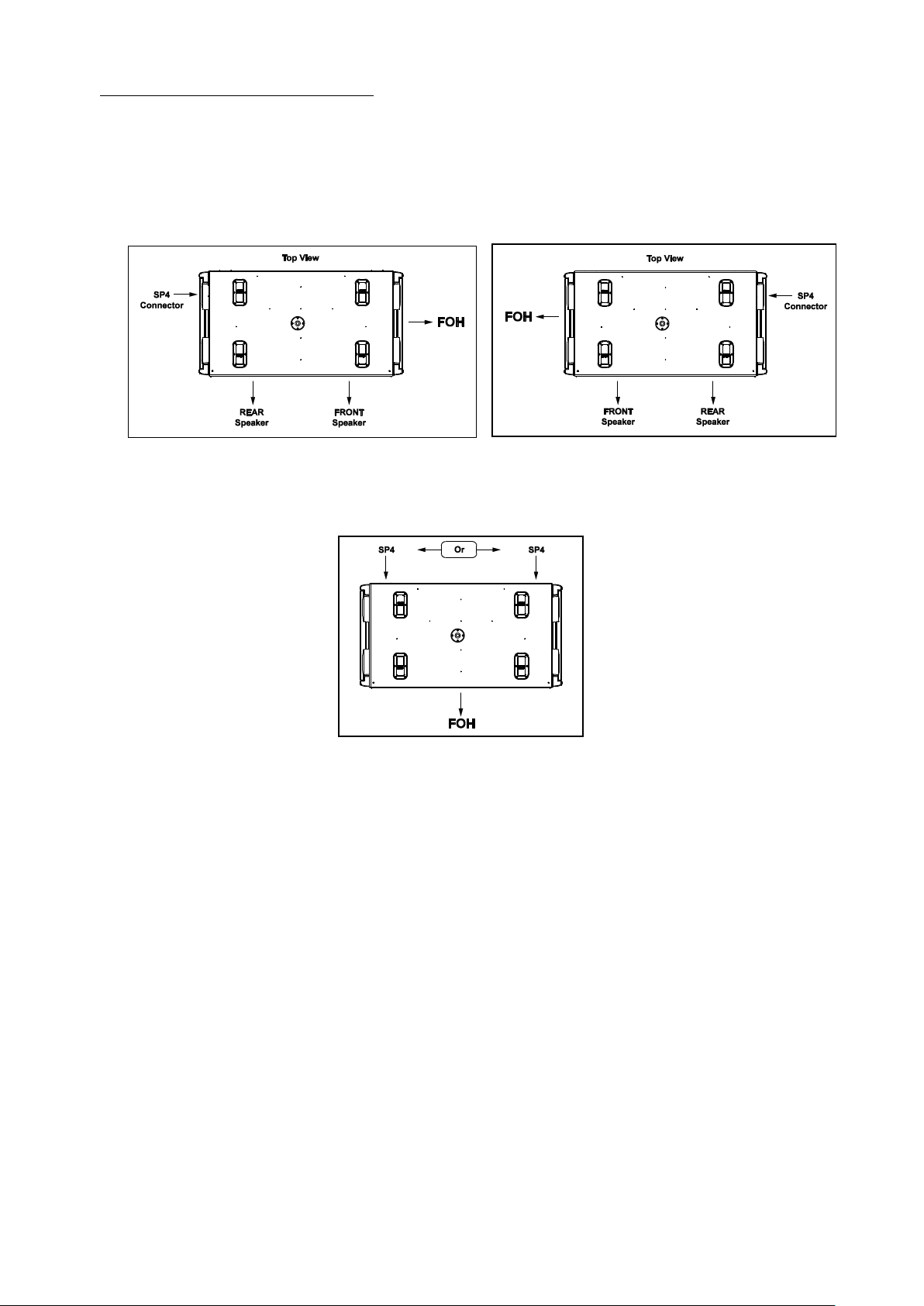
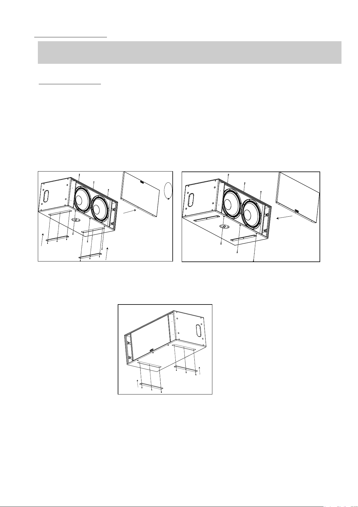
2.1.3 Configuring connector and owner plates
Owner and connector plates can be exchanged depending on chosen directional configuration.
Please note that connector plates can pass through the holes, it is therefore not required to unsolder the connectors.
Directional Mode: it is recommended to install the connector panel on the side which supports the rigging plates. Connection
side is always opposite to FOH (main lobe direction)
Connector plate in Directional Mode
Omni Mode: it is recommended to install the connector panel on the side opposite to the drivers (factory default configuration)
Connector PLATE IN Omni Mode
RS GENERAL SET-UP INSTRUCTIONS
Page 10 / 76 System Manual RS Series
2.2 Cabling
NEXO recommends the exclusive use of multi-conductor cables to connect the system: the cable kit is compatible with all the
cabinets, and there is no possible confusion between LF, MF and HF sections.
Cable choice consists mainly of selecting cables of the correct sectional dimension (size) in relation to the load resistance and
the cable length. Too small a cable section will increase both its serial resistance and its capacitance; this reduces the electrical
power delivered to the loudspeaker and can also induce response (damping factor) variations.
For a serial resistance less or equal to 4% of the load impedance (damping factor = 25), the recommended cable length is given
by:
L
max
= Z x S S in mm2, Z in Ohm, L
max
in meters
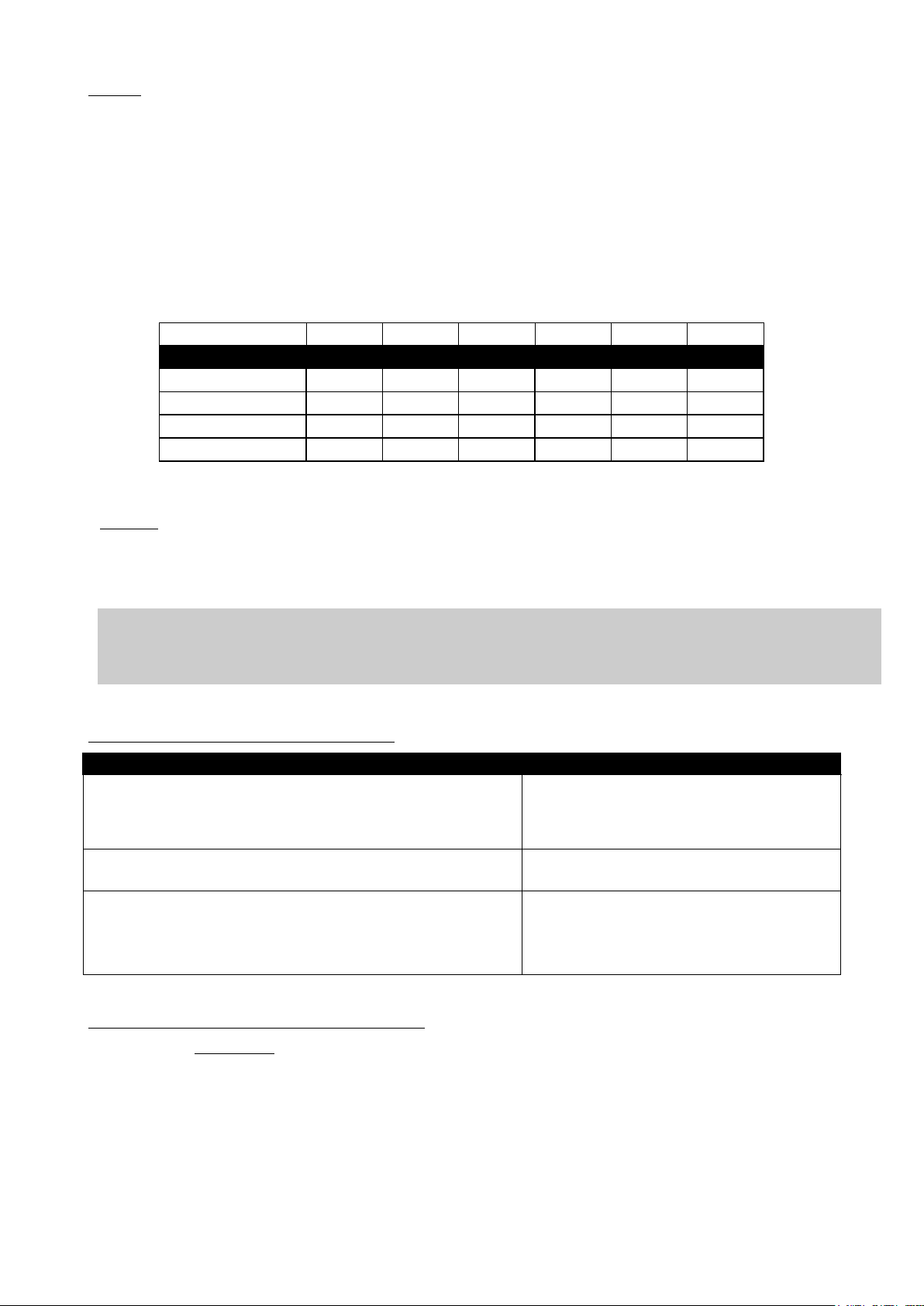
The table below indicates these values, for 3 common sizes.
Load Impedance ()
2
2.6 4 5.3 8 16
Cable section
Recommended Cable Length
1,5 mm² (AWG #15)
3m/10ft
3m/13ft
6m/20ft
8m/26ft
12m/39ft
24m/79ft
2,5 mm² (AWG #13)
5m/16ft
7m/23ft
10m/33ft
13m/44ft
20m/66ft
40m/131ft
4 mm² (AWG #11)
8m/26ft
10m/33ft
16m/52ft
21m/70ft
32m/105ft
64m/210ft
6 mm2 (AWG #9)
12m/40ft
16m/52ft
24m/79ft
32m/104ft
48m/160ft
96m/315ft
Maximum allowed length is 4 times recommended length.
Example:
Each RS18 driver has a 8 nominal impedance; in omni mode, both loudspeakers can be driven in parallel on one amplifier
channel, presenting therefore a 4 load impedance.
Recommended length for 4mm2 / (AWG#11) is 16m / 52ft, maximum allowed length is 64m / 208ft.
IMPORTANT
Long speaker cables induce capacitive effects – up to hundreds of pF depending on the quality of the
cable - with a low-pass effect on high frequencies. If long speaker cables must be used, ensure that they
do not remain coiled while in use.
2.3 RS15 and RS18 recommended amplification
NEXO TD Controllers
Recommended amplification
NXAMP4x1mk2 Powered Controller Bridged Stereo mode (2x2.6kW/4)
1 x RS15 in omni mode (drivers in //) per bridged
channels
1 x RS18 in omni mode (drivers in //) per bridged
channels
NXAMP4x2mk2 Powered Controller 4 channels mode (4x2.5kW/2)
1 x RS15 in omni mode (drivers in //) per channel
2 x RS15 in directional mode: 2 channels
NXAMP4x4mk2 Powered Controller 4 channels mode (4x4.5kW/2)
2 x RS15 in omni mode (drivers in //) per channel
4 x RS15 in directional mode: 2 channels
1 x RS18 in omni mode (drivers in //) per channel
2 x RS18 in directional mode: 2 channels
2.4 RS15 and RS18 setups on NEXO TD Controllers
Please consult nexo-sa.com for NEXO TD Controllers firmware information.
CONNECTION DIAGRAMS
System Manual RS Series Page 11 / 76
3 CONNECTION DIAGRAMS
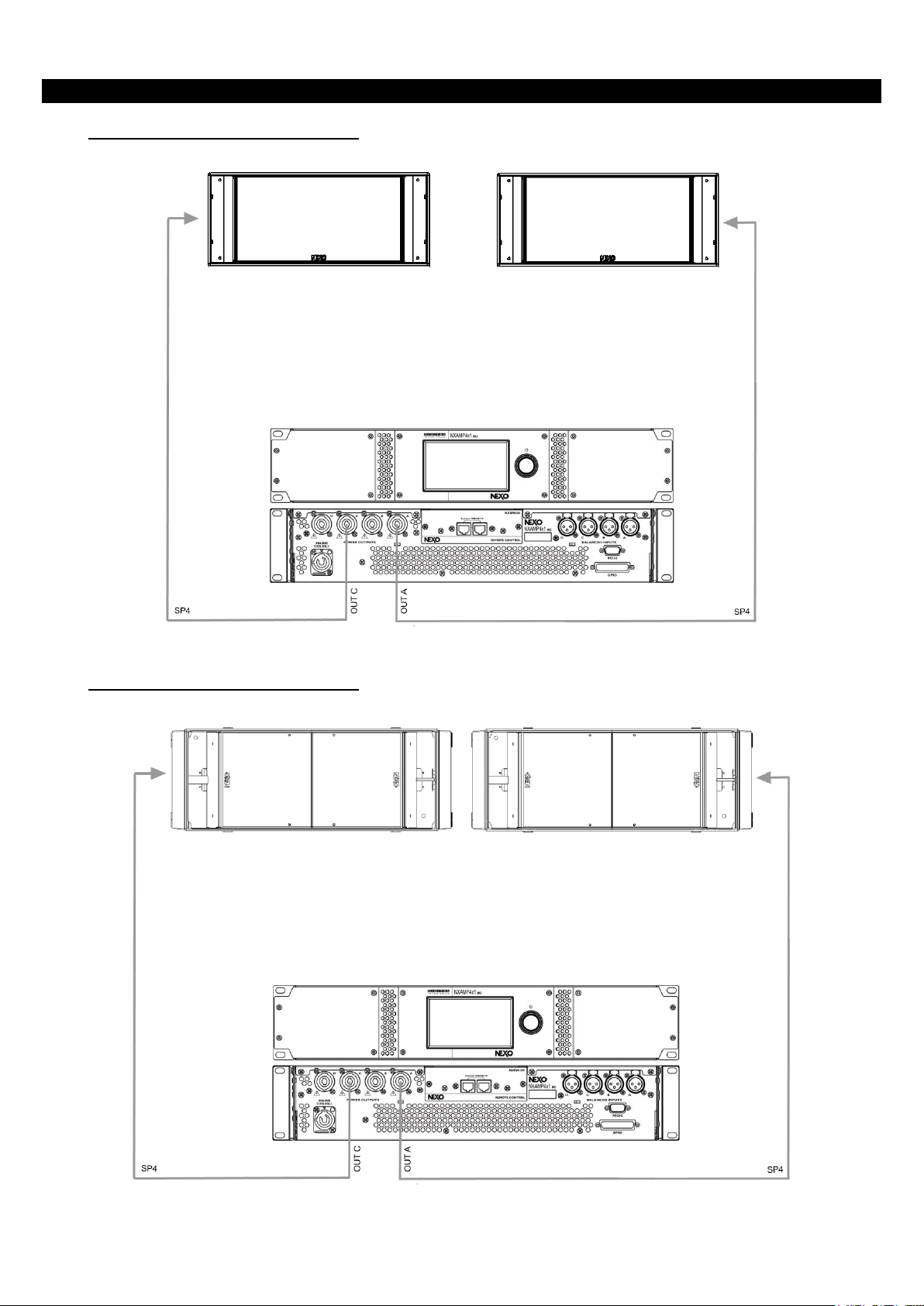
3.1 RS15 / NXAMP4x1mk2 (Bridge Stereo)
3.2 RS18 / NXAMP4x1mk2 (Bridge Stereo)
CONNECTION DIAGRAMS
Page 12 / 76 System Manual RS Series
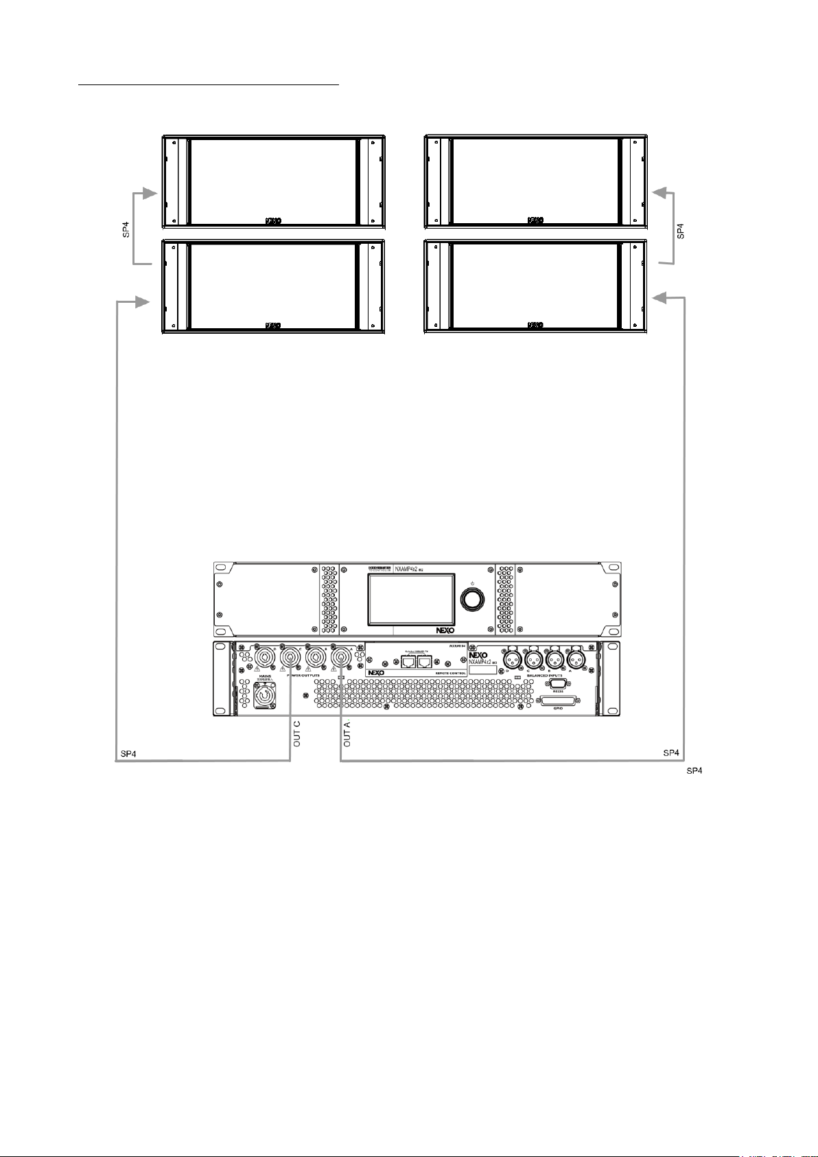
3.3 RS15 / NXAMP4x2mk2 (4 channels mode)
CONNECTION DIAGRAMS
System Manual RS Series Page 13 / 76
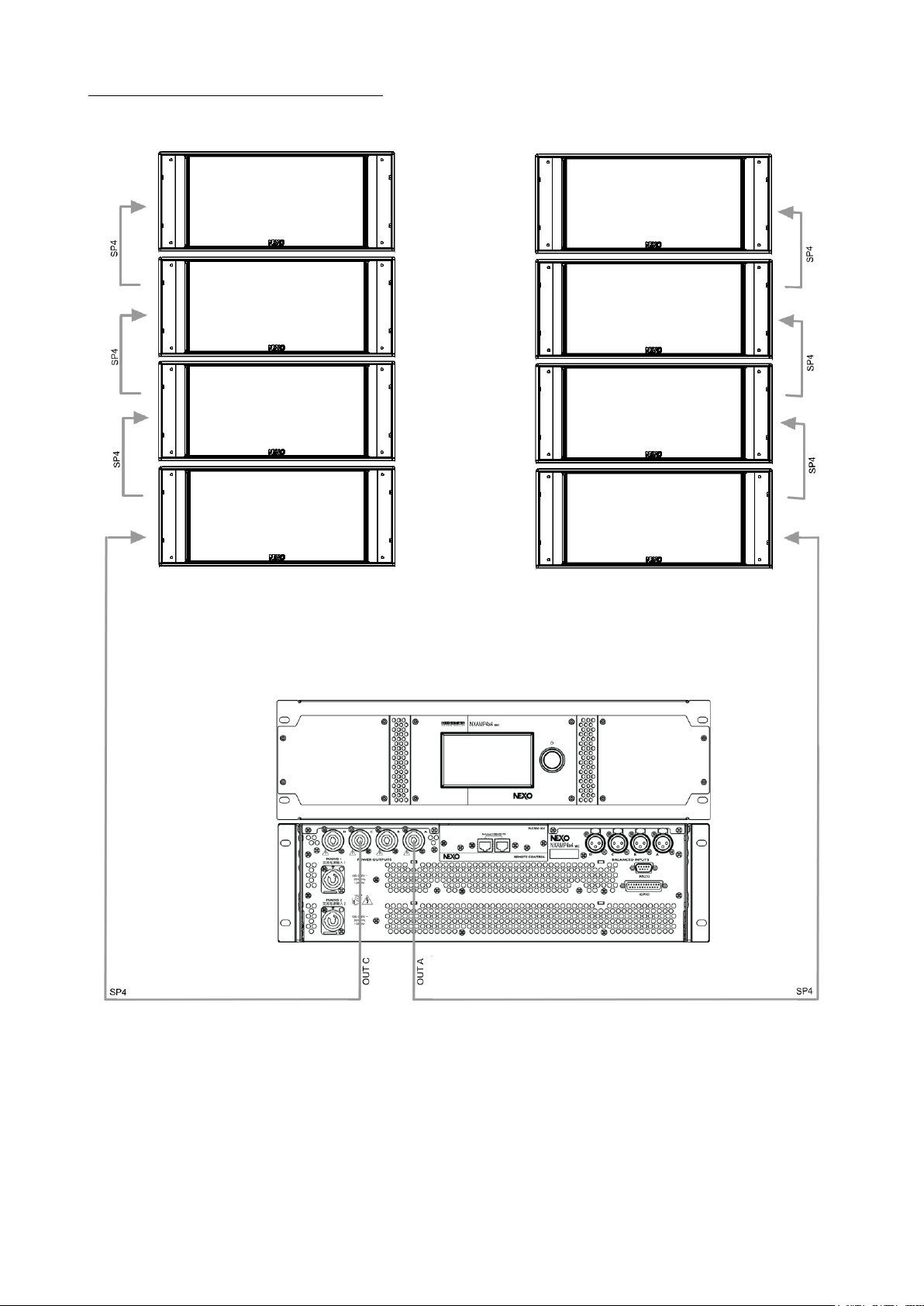
3.4 RS15 / NXAMP4x4mk2 (4 channels mode)
CONNECTION DIAGRAMS
Page 14 / 76 System Manual RS Series
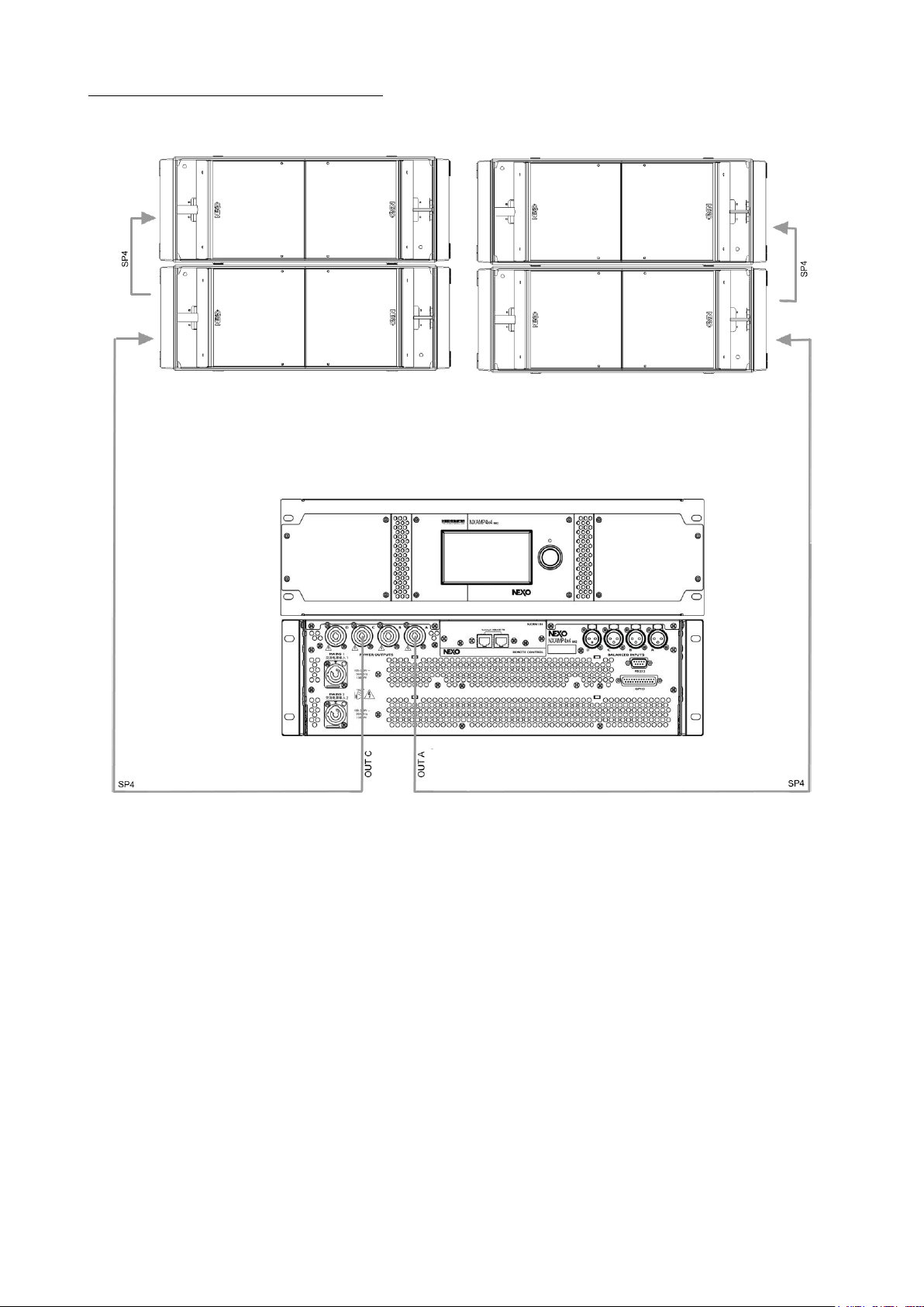
3.5 RS18 / NXAMP4x4mk2 (4 channels mode)

NS-1 SIMULATION SOFTWARE
System Manual RS Series Page 15 / 76
4 NS-1 SIMULATION SOFTWARE
NS-1 software is a R&D simulation tool derived application. It processes measured speaker data with complex mathematical
algorithms to assist the user in optimizing system design.
NS-1 is an easy to use tool that allows to shape the energy leaving the cluster to fit the audience. It predicts pressure levels
radiated from the system to ensure enough cabinets are provided for the application, as well as mechanical constraints for safe
flown systems.
In addition, it provides mechanical information for all clusters in agreement with Structural Analysis Reports (available in the
Help section): dimensions, weight, gravity centre position, forces, moments, working load and safety factor.
NS-1 installation package includes all NEXO User Manuals, Structural Analysis Reports and Certificates PDF files.
NS-1 is a freeware available on nexo-sa.com
IMPORTANT
Never install a RS15 or RS18 cluster without checking its acoustical performances and mechanical safety
in NS-1 prior to installation.
Any question or bug report please contact technical@nexo.fr

RS HARDWARE SETUP PROCEDURE
Page 16 / 76 System Manual RS Series
5 RS HARDWARE SETUP PROCEDURE
Before proceeding with assembly of RS arrays, please ensure that the components are present and undamaged. A component
list is appended to this manual. In the event of any shortage, please contact your supplier.
For maximum efficiency the RS rigging system requires three experienced persons for set-up: typically, one motor hoist operator,
and one operator per side of the array. Good synchronisation and crosscheck between the operators are key elements for a
reliable and safe set-up.
5.1 Safety first
RS Rigging System structural computations and related documents are available in NS-1 or at NEXO (info@nexo.fr) upon
request.
We include this section to remind you of safe practice when flying the RS system. Please read it carefully. However, user must
always apply his or her knowledge, experience and common sense. If in any doubt, seek advice from your supplier or NEXO
agent.
This manual offers guidance only for RS systems. References in this manual to other rigging equipment such as motor hoists,
steels, shackles etc. are made to clarify the description of rigging procedures. The user must ensure that operators are properly
trained by other agencies in the use of these items.
The RS Rigging System has been optimised for the deployment of vertical arrays of RS loudspeakers. No angle adjustment is
allowed between cabinets.
The RS Rigging System is a professional RS Rigging System and provided with suitable safety equipment should deploy RS
Arrays. Misuse of the RS Rigging System could lead to dangerous consequences.
Used and maintained correctly, the RS Rigging System will give many years of reliable service in portable systems. Please take
the time to read and understand this manual. Cluster configuration must be implemented and validated in NS-1 prior to
installation.
5.1.1 Flown systems safety
Always inspect all the rigging components and cabinets for damage before assembly. Pay special attention to the lifting points,
and safety clips. If you suspect that any of the components are damaged or defective, DO NOT USE THE AFFECTED PARTS.
Contact your supplier for replacements.
Read this manual carefully. Also, be familiar with the manuals and safe working procedures for any ancillary equipment that will
be used with the RS Rigging System.
Cluster configuration must be implemented and validated in NS-1 prior to installation.
Ensure that all local and National regulations regarding the safety and operation of flying equipment are understood and adhered
to. Information on these regulations can usually be obtained from Local Government Offices.
When deploying a RS system always wear protective headwear, footwear and eye protection.
Do not allow inexperienced persons to handle a RS system. Installation personnel should be trained in loudspeaker flying
techniques and should be fully conversant with this manual.
Ensure that motor hoists, hoist control systems and ancillary rigging components are currently certified as safe and that they
pass a visual inspection prior to use.
Ensure that public and personnel are not allowed to pass beneath the system during the installation process. The work area
should be isolated from public access.
Never leave the system unattended during the installation process.
Do not place any object, no matter how small or light, on top of the system during the installation procedure. The object may fall
when the system is flown and is likely to cause injury.
Secondary safety steels must be installed once the system has been flown to the operating height. Secondary steels must be
fitted irrespective of requirements of the local safety standards applicable to the territory.
Ensure that the system is secure and prevented from pivoting around the motor hoist.
Avoid any form of excessive dynamic loading to the assembly (structural computations on RS Rigging System are based on a
1/1.2 factor for hoist or motor acceleration).
NEVER attach any item to the RS system other than the RS accessories.
When flying outdoor systems ensure that the system is not exposed to excessive wind or snow loads and is protected from
rainfall.
In case of wind greater than 8 on Beaufort scale (72km/h – 45mph), a touring system has to be landed or an additional securing
has to be implanted.

RS HARDWARE SETUP PROCEDURE
System Manual RS Series Page 17 / 76
For fixed installations, wind loading has to be taken into account in accordance to the national standards.
The RS Rigging System requires regular inspection and testing by a competent test centre. NEXO recommend that the system
is load tested and certified annually or more frequently if local regulations require.
When de-rigging the system ensure that the same duty of care is given to the procedure as for the installation. Pack RS
components carefully to prevent damage in transit.
5.1.2 Ground stacking safety
Statistically, many more injuries occur due to unstable ground stacked PA systems than those associated with flown systems.
There are several reasons for this fact, however the message is clear:
Always survey the supporting structure upon which a ground stack is to be built. Always look beneath PA wings to inspect the
deck support and if necessary, ask for the stage scrims and dressings be removed to allow access.
If the stage surface slopes, as it does in some theatres, ensure that the system is prevented from sliding forwards due to
vibration. This may require the fitting of timber battens to the stage floor.
For outdoor systems ensure that that the system is protected from wind forces which might cause the ground stack to become
unstable. Wind forces can be huge, especially upon large systems, and should never be underestimated. Observe
meteorological forecasts, calculate the “worst case” effect upon the system prior to erection and ensure that the system is
secured appropriately.
Take care when stacking cabinets. Always employ safe lifting procedures and never attempt to build stacks without sufficient
personnel and equipment.
Never allow anyone, whether operators, artists or members of the public to climb onto a ground stacked PA system. Anyone
who needs to climb over 2m (6 ft) high should be fitted with suitable safely equipment including a clip-on harness. Please refer
to local Health and Safety legislation in your territory. Your dealer can help with advice on access to this information.
Apply the same attention to all safety matters when de-stacking systems.
Be aware that safety procedures are as important in the truck and in the warehouse as they are at the venue.
5.1.3 Contacts
Correct training is fundamental to safe practise when working with loudspeakers flying systems. NEXO recommend that users
contact local industry associations for information on specialist course.
Information for International training agencies can be obtained by contacting either:
The Production Services Association (PSA),
School Passage,
Kingston-upon-Thames,
KT1 SDU Surrey,
ENGLAND
Telephone: +44 (0) 181 392 0180
www.psa.org.uk/
Rigstar Training and Testing Center
82 Industrial Dr. Unit 4
Northampton, Massachusetts 01060 U.S.A.
Phone: 413-585-9869
www.rigstar.com/
ESTA
Entertainment Services & Technology
Association
875 Sixth Avenue, Suite 1005
NEW YORK, NY 10001 USA
Phone: 212-244-1505
www.esta.org
RS HARDWARE SETUP PROCEDURE
Page 18 / 76 System Manual RS Series
5.2 RS15 General Instructions
IMPORTANT
IN ORDER TO PREVENT SCREWS FROM GETTING LOOSE, USE BLOCKING LIQUID LOCTITETM 243 OR
EQUIVALENT FOR ALL SCREWS USED WITH RS15 ACCESSORIES.
5.2.1 RS15 “Left” and “Right”
NEXO RS15 Subwoofer is delivered with a pair of skids to be mounted on the cabinet.
NEXO recommends to create pairs of “RS15 LEFT” and “RS15 RIGHT” for optimized flexibility.
Benefits of such recommendation are related to directional use in array configurations, where RS15s are to be positioned back
to back, face to face or in vertical columns alternating speaker side.
However, users might prefer to have all RS15s configured identically, in which case they should all be “RS15 RIGHT” so that
skids are opposite to pole stand hole.
Mounting skids on the pole stand hole side defines a “RS15 LEFT”.
In such a case, front grid must be removed, flipped over and reinstalled so that NEXO logo appears on the same side than the
skids.
CONFIGURING RS15 AS LEFT
Mounting skids opposite to the pole stand hole side defines a “RS15 RIGHT”.
CONFIGURING RS15 AS RIGHT
RS HARDWARE SETUP PROCEDURE
System Manual RS Series Page 19 / 76
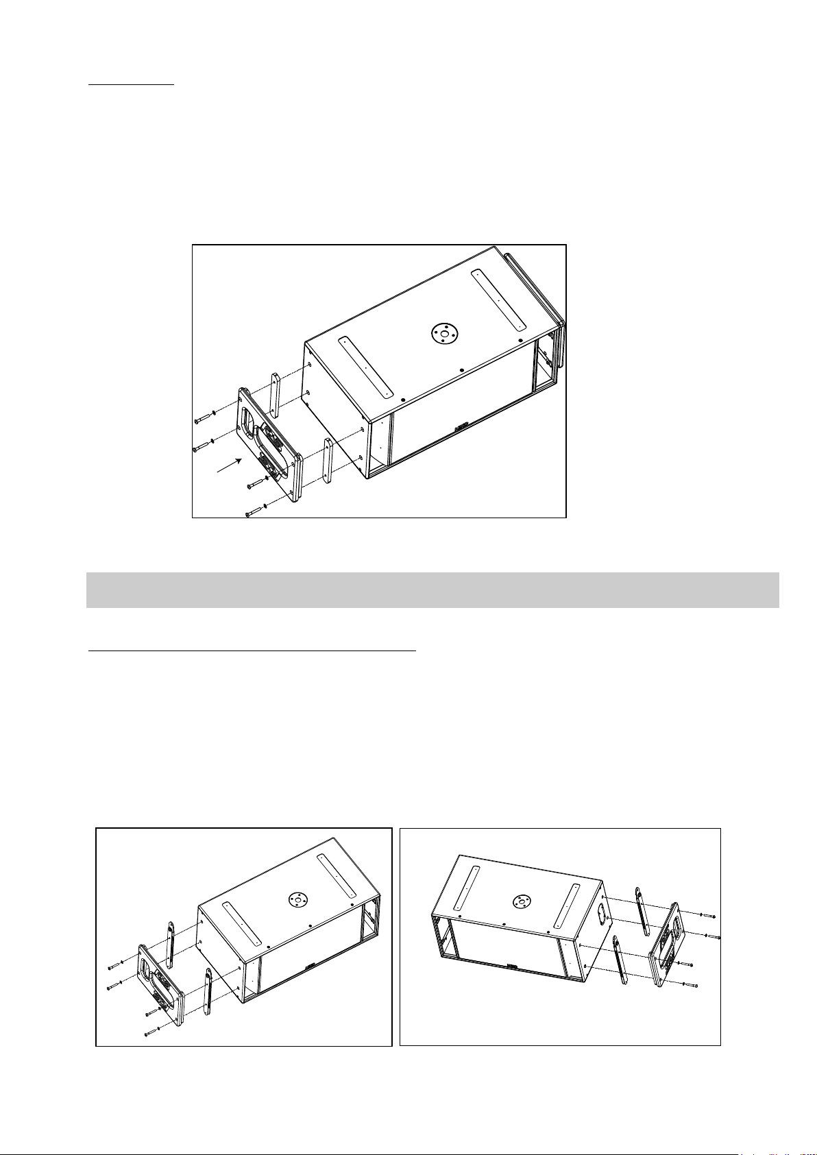
5.2.2 RS15 handles
Procedure
- Remove the four screws on each side of RS15
- Fill each screw hole with Loctite 243 or equivalent
- Position spacers and handles according to below drawing (vertical opening must be aligned with connector panel or owner’s
plate)
- Insert the four washers and screws provided with the RST-HANDLES15 kit and tight them
INSTALLING RS15 HANDLES
IMPORTANT
RS15 handles must not be used to fly RS15’s (through illegal use of straps for example)
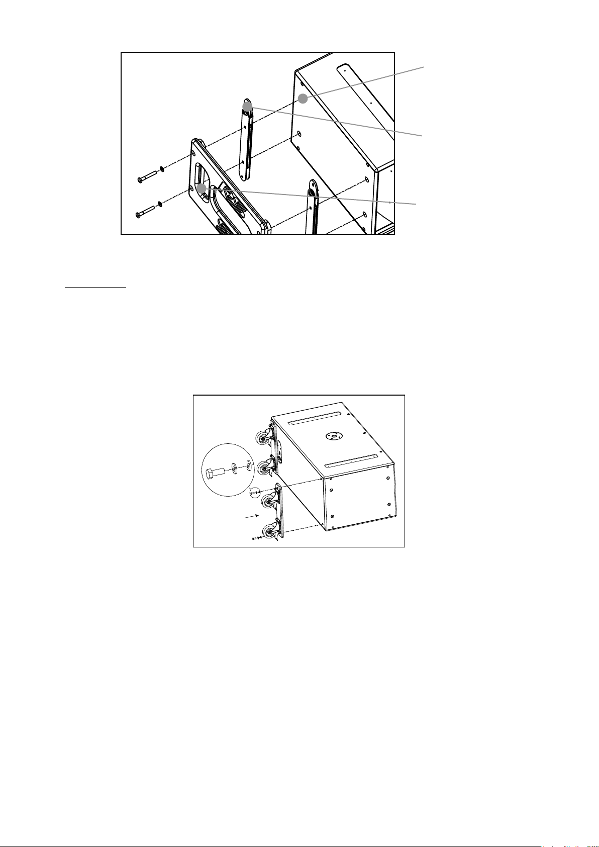
5.2.3 RS15 Flying Plates with handles (touring applications)
Procedure
- Remove the four screws on each side of RS15
- Fill each screw hole with Loctite 243 or equivalent
- Position flying bars so that articulated link bars are opposite to skids, ie at the top of the cabinet
- Position handles according to below drawing (vertical opening must be aligned with connector panel or owner’s plate)
- Insert the four washers and screws provided with the RST-FLPLATES15 kit and tight them (torque value must be 10 Nm
minimum)
INSTALLING RS15 FLYING PLATES AND HANDLES
RS HARDWARE SETUP PROCEDURE
Page 20 / 76 System Manual RS Series
5.2.4 RS15 Wheels
Procedure
- Remove the four screws on RS15 back panel
- Fill each screw hole with Loctite 243 or equivalent
- Position wheels according to below drawing
- Insert the 8 washers and 4 screws provided with the RST-WHEELS15 kit (see detail in below drawing) and tight them
Holes to be filled
with Loctite 243
Link Bars going
upwards opposite
to skids
Vertical Openings
opposite to
loudspeakers

RS HARDWARE SETUP PROCEDURE
System Manual RS Series Page 21 / 76
5.2.5 RS15 Dolly
IMPORTANT
Transporting RS15 on Dolly requires that flying plates are installed on ALL CABINETS so that RS15’s can
be secured together.
RS15 Dolly is designed for up to 3 RS15’s and bumper. Never exceed these quantities.
The first RS15 must be locked to the RS15 dolly using four push-pins according to below drawing.
Subsequent RS15s are stacked on top using four push-pins per additional cabinet to secure the assembly.
Bumper is to be attached to the top cabinet.
RS HARDWARE SETUP PROCEDURE
Page 22 / 76 System Manual RS Series
5.3 RS18 General Instructions
IMPORTANT
IN ORDER TO PREVENT SCREWS FROM GETTING LOOSE, USE BLOCKING LIQUID LOCTITETM 243 OR
EQUIVALENT FOR ALL SCREWS USED WITH RS18 ACCESSORIES.
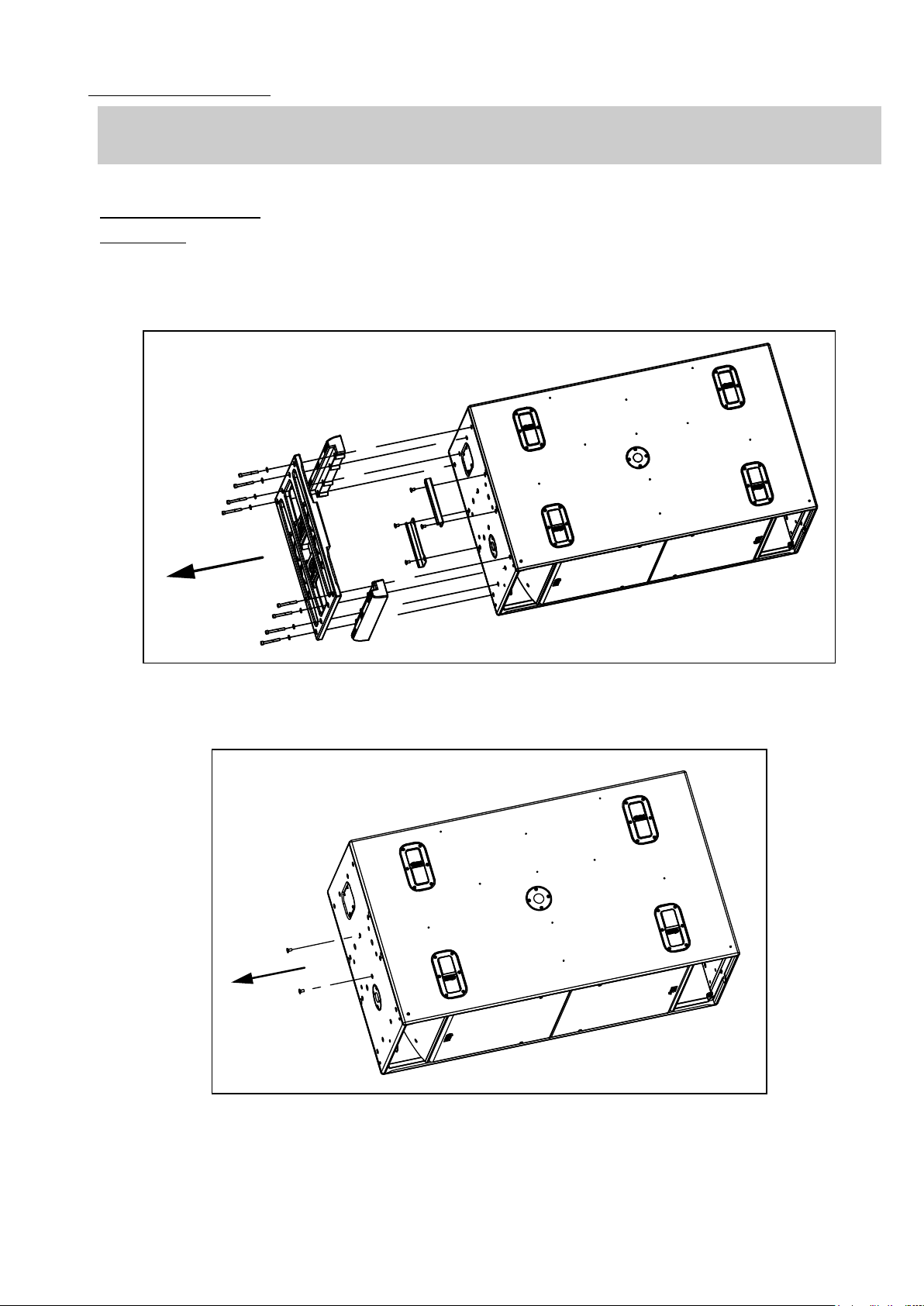
5.3.1 Mounting Rigging Plate
RS18 Painted
Procedure
- Remove the twelve screws on each side of RS18
- Remove the four screws on each side of RS18
- Insert Spacer between cabinet and Rigging plates
- Fill each screw hole with Loctite 243 or equivalent
- Tighten the 6 screws alternately, at the rate of 4 revolutions per screw

RS HARDWARE SETUP PROCEDURE
System Manual RS Series Page 23 / 76
- Fill each screw hole with Loctite 243 or equivalent
- Insert the 8 handles washers and screws and tight them
INSTALLING PAINTED RS18 RIGGING PLATES
IMPORTANT
RS18 handles must not be used to fly RS18’s (through illegal use of straps for example)
 Loading...