

Nexo RS15, Ray Sub RS15 User Manual

Ray Sub Series
RS15 Subwoofer
User Manual
RaySub Series User Manual V1.01
Date: 10/12/2007

Page 2/58 INTRODUCTION
GOING ONE STEP FURTHER IN LOW FREQUENCY CONTROL: RAY SUB TECHNOLOGY
Radiation control of low frequencies is hard to achieve due to wavelength being larger
than cabinet size. Consequently, most of current subwoofers available on the audioprofessional market are omnidirectional.
Drawbacks in using omnidirectional subwoofers are known by experienced engineers:
- Low Frequency sound pressure level is typically higher on stage than over the
audience; high-pass filters are mandatory in almost all microphones inputs t o avoid
feedback from the microphones to the subwoofers. Moreover, gain from microphone
to speakers is highly limited due to that feedback (reinforcing a double-bass can be
an enormous challenge);
- Indoor environments typically have much higher reverberation time in the Low
Frequency range than in the mid and high Frequencies. This characteristic is
emphasized by the omnidirectional pattern of conventional subwoofers (all sound
engineers experienced kick drum lasting forever);
- Many outdoor shows occur nearby residential areas where noise constraints are very
restrictive; in such cases, low frequencies levels over the audience have to be
limited so that environment criterias are fulfilled (possibly leading to unacceptable
wideband limitations).
Gradient subwoofers provide an elegant solution to the above issues, based on a
technology that is a simple transposition to sound sources of what has been applied for
decades in microphones: radiated field derives from pressure differences generated
from two (or more) sources:
- Rear radiation is lowered by more than 12 dB, which benefits to stage as well as to
neighbours;
- Direct to reverberant ratio is increased by nearly 6 dB in the low frequency range
(which potentially gives back a kick drum its original “punch”).
However, there are efficiency limitations: gain in lower bandwidth is reduced when
sources become too close in relation to wavelength, and pattern control is limited in
upper bandwidth when both sources interfere destructively in the radiation axis.
Operating bandwidth were efficiency combines with pattern control is around 2 octaves.
Poor correlation between cabinet design and targeted specifications leads to two (and
eventually more) drivers in directional mode producing less energy than one driver in
omnidirectional mode, which is not acceptable for simple practical aspects such as
weight and volume.
It is now 5 years that NEXO has released its first gradient subwoofer – the CD12 -,
complemented since then with the CD18 and the GEO SUB. These have been quickly
adopted worldwide as standards, and are considered today as state of the art
subwoofers. This success is a consequence of proper cabinet design and optimized
definition of phase relations through sophisticated DSP algorithms leading to high
directional control and SPL output.

INTRODUCTION Page 3/58
With RAY SUB patent pending technology, NEXO is again moving one step forward. RAY
SUB technology is about optimizing positioning and phase relationship of radiating
surfaces in vented enclosures, so that acoustic distance from rear to front sections
always increases as frequency decreases; consequently, rear and front section always
sum up efficiently – typically 5 dB gain from rear section in the forward direction – and
cancel in the rearward direction.
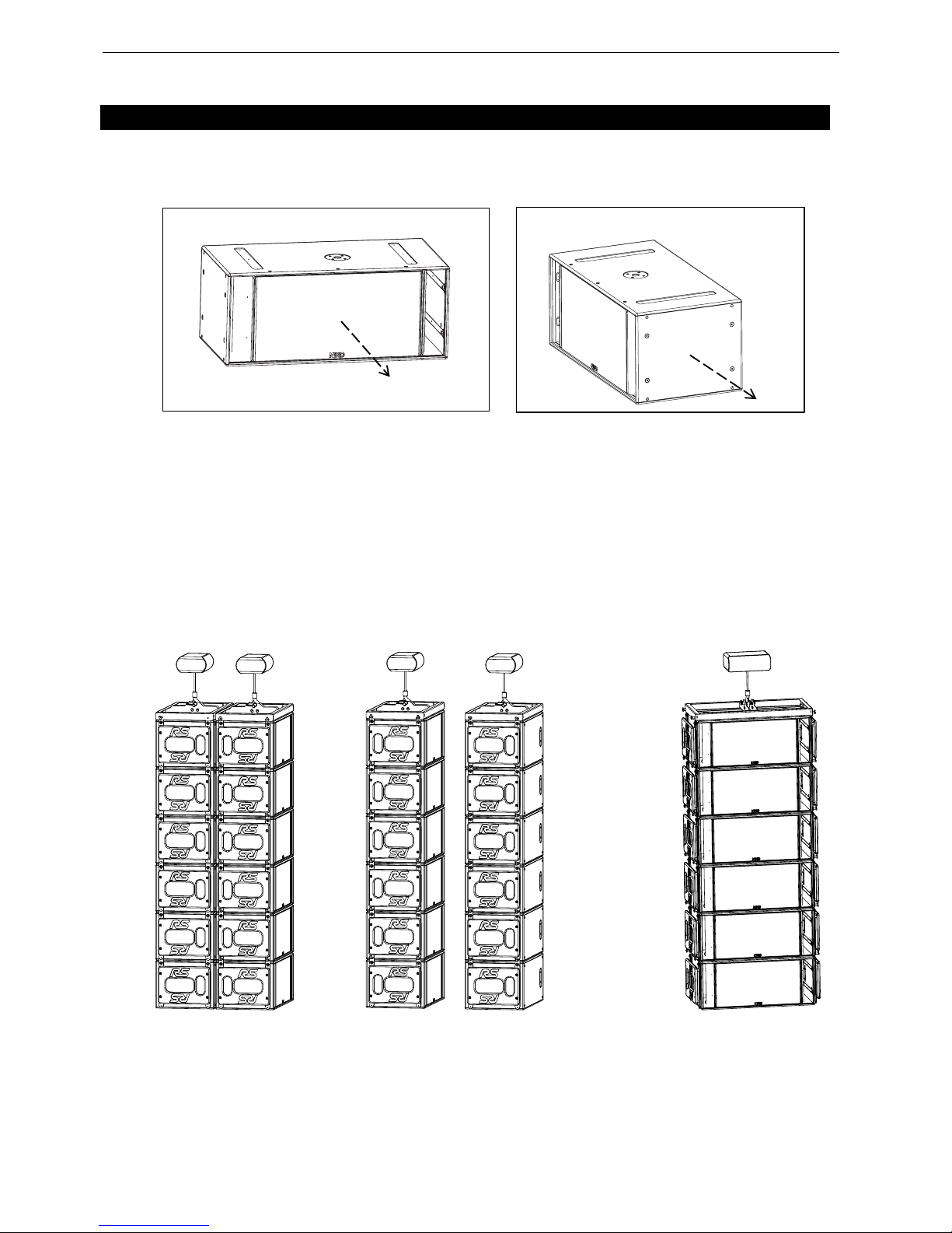
Used as a single cabinet, RAY SUB Technology allows the same cabinet to be configured
for any polar pattern, omnidirectional as a standard direct radiating subwoofer when
speakers are facing the audience, or highly directional when cabinet is rotated speakers
sideways or upwards.
Used in arrays, RAY SUB subwoofers can be set back to back, front to front, in vertical
columns, and beam-steered upwards or downwards provided column length is sufficient.
NEXO RAY SUB technology brings a never achieved low frequency directional control to
the sound reinforcement industry, raising one more time NEXO standards.
Page 4/58 INTRODUCTION
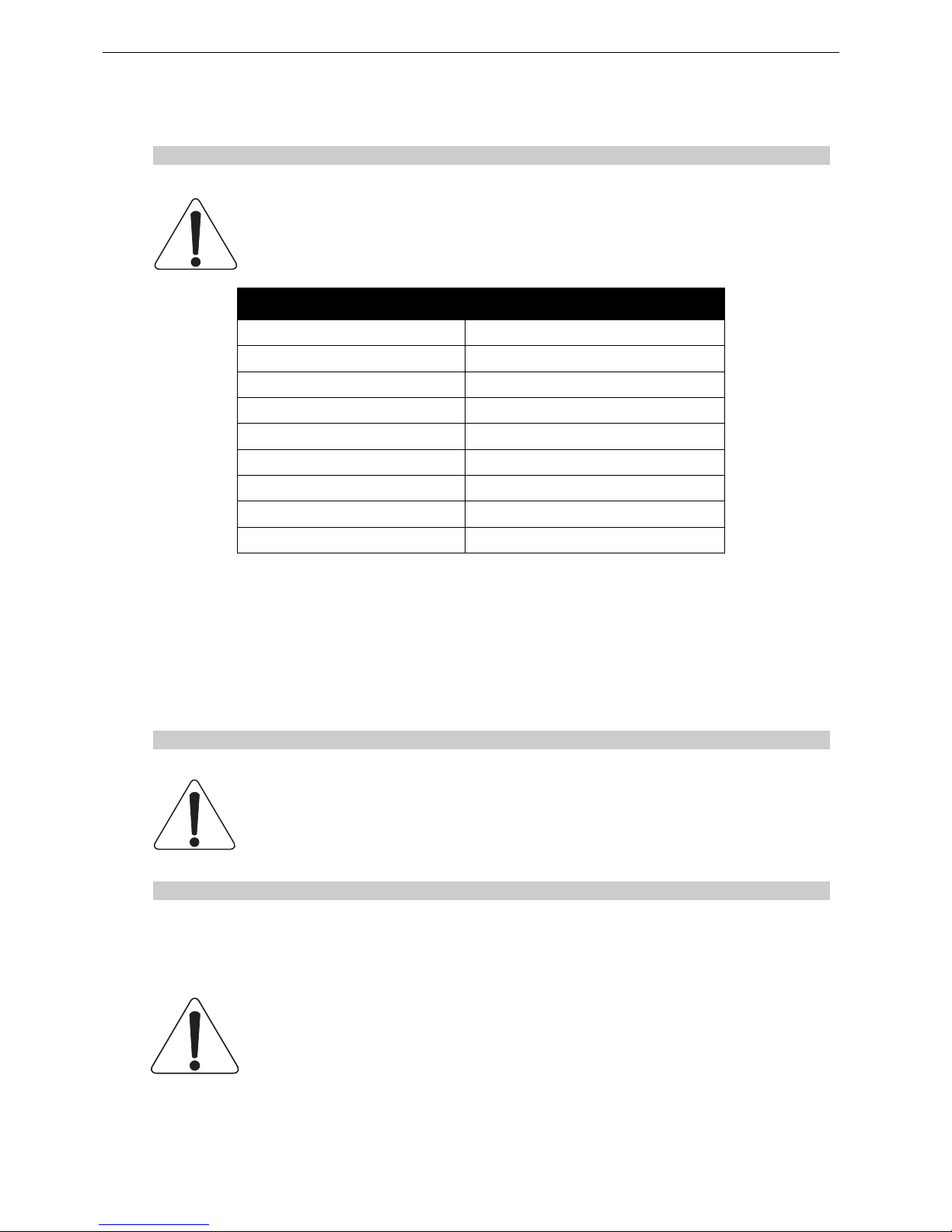
SAFETY ISSUES
IMPORTANT NOTICE CONCERNING HIGH SOUND PRESSURE LEVELS
Exposure to extremely high noise levels may cause a permanent hearing loss.
Individuals vary considerably in susceptibility to noise-induced hearing loss, but nearly
everyone will lose some hearing if exposed to sufficiently intense noise for a sufficient of
time. The U.S. Government’s Occupational and Health Administration (OSHA) has
specified the following permissible noise level exposures: Sound Duration Per
Day In Hours Sound Level dBA, Slow Response
8 90
6 92
4 65
3 97
2 100
1 ½ 102
1 105
½ 110
¼ or less 115
According to OSHA, any exposure in excess of the above permissible limits could result in some
hearing loss. Ear plugs or protectors to the ear canals or over the ears must be worn when operating
this amplification system in order to prevent a permanent hearing loss, if exposure is in excess of the
limits as set forth above. To ensure against potentially dangerous exposure to high sound pressure
levels, it is recommended that all persons exposed to equipment capable of producing high sound
pressure levels such as this amplification system be protected by hearing protectors while this unit is in
operation.
SYSTEM RIGGING SAFETY RULES
Before use of RS Subwoofers, please ensure that anyone involved in system deployment
understands the rigging and stacking Safety rules as described in the ”RS15
HARDWARE, SAFETY FIRST” section. Failure to do this exposes people to potential
injury or death.
ELECTRICAL SAFETY
WARNING ! GEO S12 TDCONTROLLER, NX242 DIGITAL CONTROLLER, NXAMP4x1 AND
NXAMP4x4 POWERED CONTROLLERS ARE CLASS 1 APPARATUS AND MUST BE EARTHED.
The green and yellow wire of the mains cord must always be connected to an installation
safety earth or ground. The earth is essential for personal safety as well as the correct
operation of the system, and is internally connected to all exposed metal surfaces.

INTRODUCTION Page 5/58
TABLE OF CONTENTS
1 Introduction ...................................................................................................................................................8
2 RS15 General Instructions.........................................................................................................................10
2.1 “RS15 Left” and “RS15 Right” ..............................................................................................................10
2.1.1 RS15 LEFT..................................................................................................................................10
2.1.2 RS15 RIGHT ...............................................................................................................................10
2.2 Mounting Optional Accessories............................................................................................................11
2.2.1 RS15 Handles .............................................................................................................................11
2.2.2 RS15 Flying Plates with handles (touring applications) ..............................................................11
2.2.3 RS15 Wheels...............................................................................................................................12
2.2.4 RS15 Dolly...................................................................................................................................13
2.3 Speaker connection .............................................................................................................................14
2.3.1 Configuring Connector and Owner plates ...................................................................................14
2.3.2 RS15 connectors .........................................................................................................................14
2.3.3 Cabling.........................................................................................................................................15
2.3.4 Example.......................................................................................................................................15
3 Amplifier selection for use with RS15 ......................................................................................................16
3.1 RS15 recommended amplification .......................................................................................................16
3.1.1 Current rating...............................................................................................................................16
3.1.2 Amplifier settings .........................................................................................................................16
3.2 RS15 and NXAMP TDControllers ........................................................................................................18
3.2.1 NXAMP connectors .....................................................................................................................18
3.2.2 RS15 and NXAMP recommended configurations .......................................................................18
4 RS15 Setups on NEXO TD Controllers .....................................................................................................19
4.1 Analogue GEOS12 TDController .........................................................................................................19
4.2 Digital NX242-ES4 and NXAMP TDControllers ...................................................................................19
5
Connection diagrams.................................................................................................................................20
5.1 RS15 with GEOS12 TDController (Mono Omni Mode)........................................................................20
5.2 RS15 with NX242-ES4 TD Controller (Stereo Omni Mode) ................................................................21
5.3 RS15 with NX242-ES4 TD Controller (Stereo Directional Mode)........................................................22
5.4 RS15 with NXAMP (Stereo Omni Mode) .............................................................................................23
5.5 RS15 with NXAMP (Stereo Directional Mode).....................................................................................24

Page 6/58 INTRODUCTION
6 RS15 Rigging Instructions ........................................................................................................................ 25
6.1 SAFETY FIRST ................................................................................................................................... 25
6.1.1 Flown Systems Safety ................................................................................................................ 25
6.1.2 Ground Stacking Safety.............................................................................................................. 26
6.1.3 Contacts...................................................................................................................................... 27
6.2 Flying RS15 arrays.............................................................................................................................. 28
6.2.1 Hoist Rating ................................................................................................................................ 28
6.2.2 Connecting first RS15 to bumper ............................................................................................... 28
6.2.3 Adjusting rigging point for horizontality....................................................................................... 29
6.2.4 Flying the second RS15.............................................................................................................. 30
6.2.5 Flying subsequent RS15’s .......................................................................................................... 31
6.3 Testing and Maintenance of the RS15 flying system .......................................................................... 32
7 General guidelines for subwoofer design ............................................................................................... 33
7.1 Low Frequency Issues ........................................................................................................................ 33
7.2 Gradient Subwoofers benefits ............................................................................................................. 34
7.3 Monophonic Design............................................................................................................................. 34
7.4 Stereo Design...................................................................................................................................... 35
8 RAY SUBs implementation ....................................................................................................................... 36
8.1 Omnidirectional Mode ......................................................................................................................... 36
8.1.1 Single RS15................................................................................................................................ 36
8.1.2 RS15 arrays................................................................................................................................ 36
8.2 Directional Mode.................................................................................................................................. 36
8.2.1 Single RS15................................................................................................................................ 36
8.2.2 RS15s pair .................................................................................................................................. 37
8.2.3 RS15s arrays .............................................................................................................................. 39
8.3 Steered RS15s arrays ......................................................................................................................... 39
8.3.1 Steering technique...................................................................................................................... 39
8.3.2 Delay values implementation...................................................................................................... 40
8.3.3 Coverage result ..........................................................................................................
................ 41
8.4 Aligning RS15s with main system ....................................................................................................... 41
8.4.1 NEXO systems acoustic reference point .................................................................................... 41
8.4.2 Precautions................................................................................................................................. 42
8.4.3 Alignment with distance measurement....................................................................................... 42
8.4.4 Alignment with phase measurement .......................................................................................... 43
8.5 Recommended installation tools and equipment ................................................................................43

INTRODUCTION Page 7/58
9 RS15 System Check List............................................................................................................................44
9.1 Are the NX Digital TDcontrollers properly configured? ........................................................................44
9.1.1 NX settings ..................................................................................................................................44
9.2 Are the amplifiers properly configured? ...............................................................................................44
9.3 Are the amps and the NX properly connected? ...................................................................................44
9.4 Are the speakers properly connected? ................................................................................................44
9.5 Final Pre-Sound Check Check.............................................................................................................45
10 RS15 Technical Specifications..............................................................................................................46
10.1 System specifications...........................................................................................................................46
10.2 Dimensions...........................................................................................................................................47
10.3 Diagrams ..............................................................................................................................................47
10.3.1 Frequency Response and Impedance ........................................................................................47
10.3.2 Polar plots....................................................................................................................................48
10.4 RS15 Accessories................................................................................................................................50
10.4.1 RS15-BUMPER ...........................................................................................................................50
10.4.2 RS15-FPLATES ..........................................................................................................................50
10.4.3 RS-15 HANDLES ........................................................................................................................50
10.4.4 RS15-WHEELS ...........................................................................................................................51
10.4.5 RS15-DOLLY...............................................................................................................................52
10.4.6 RS15 Push-Pins (BLGEOS)........................................................................................................52
10.5 GEO S12 Analogue TDController ........................................................................................................53
10.5.1 Specifications ..............................................................................................................................53
10.5.2 Front and Rear Panel view..........................................................................................................53
10.6 NX242 Digital TDController with NX-Tension Card .............................................................................54
10.6.1 Specifications ..............................................................................................................................54
10.6.2 Front and Rear Panel view..........................................................................................................54
10.7 NXAMP4x1 & NXAMP4x4 Powered Digital TDControllers..................................................................55
10.7.1 Specifications ..............................................................................................................................55
10.7.2 Front and Rear Panel view..........................................................................................................56
11 RS15 Parts & Accessories List.............................................................................................................57
11.1 Modules & Control Electronics List ........................................................................................
..............57
11.2 Accessories List ...................................................................................................................................57
12 USER NOTES ..........................................................................................................................................58
Page 8/58 INTRODUCTION
1 INTRODUCTION
Thank you for selecting a NEXO RS15 Subwoofer System. This manual is intended to provide you with
necessary and useful information about your RS System, which includes the following products:
• RS15 is a Directivity Configurable Subwoofer, which comprises two 15” (38cm) long excursion
Neodynium direct radiating drivers mounted in a dual volume vented enclosure with aerodynamic
profiled vents; its coverage ranges from omnidirectional to highly directional and its frequency
response extends from VLF to LF ranges (35Hz-200Hz). Painted and Carpeted versions are
available.
• a full range of accessories that provides safe, flexible and simple means of transporting and
installing RS15 subwoofers in fixed installation as well as in touring applications. These include
flying hardware and dolly.
INTRODUCTION Page 9/58
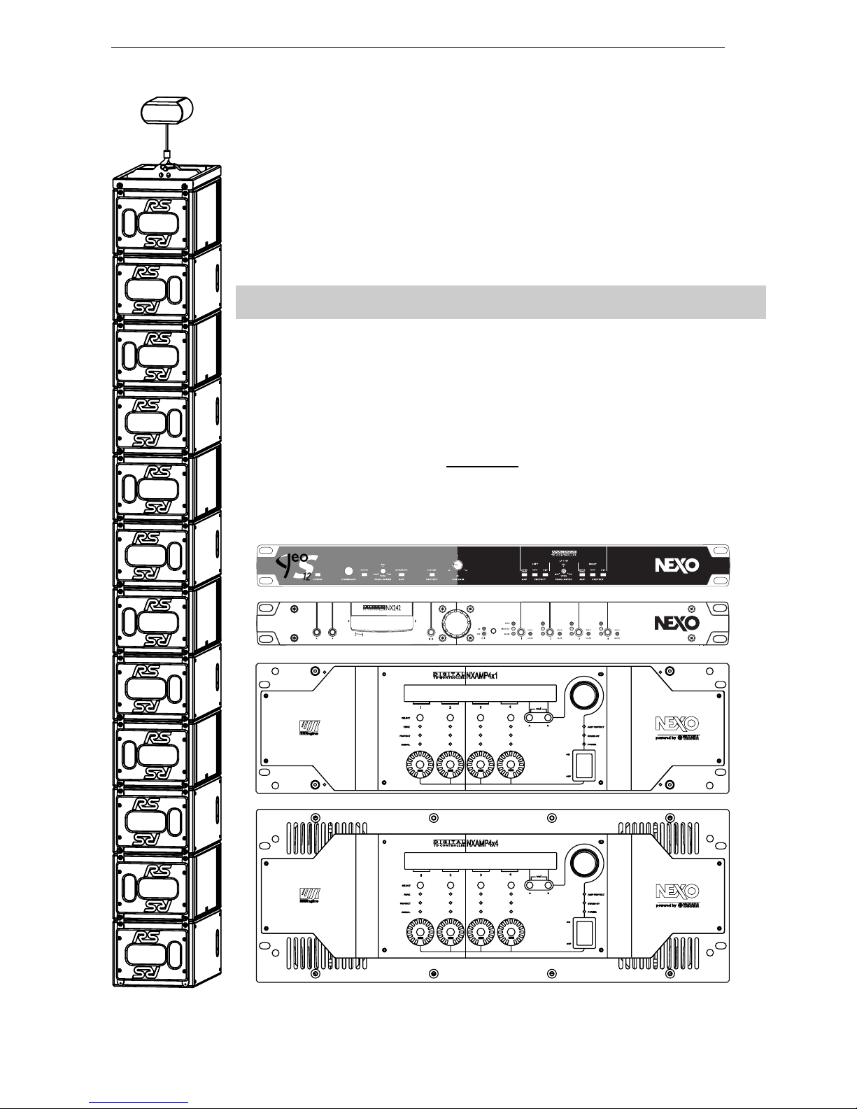
As for all NEXO systems, the RS15 is controlled, powered and monitored by dedicated NEXO
TDControllers:
• GEO S12 TDController is based on PS analogue TDController design, and
provides full control for RS15 in omnidirectional mode associated to Geo
S12. It has 2 analogue inputs (Left and Right) and 3 analogue outputs
(RS15 Mono Omni, GeoS12 Left and GeoS12 Right);
• NX242-ES4 Digital TDController provides comprehensive control of RS15
loudspeakers in multiple configurations. It allows Ethersound
TM
digital
audio networking, as well as remote control for all units in the network. It
has 2 analogue / 4 digital inputs and 4 analogue / 4 digital outputs;
IMPORTANT : NX242 must be equipped with NX-Tension Card (ES4 or CAI)
to access RS15 setups
• NXAMP4x1 and NXAMP 4x4 are Powered Digital Controllers, providing
full control and amplification for RS15 in multiple configurations. Both
devices feature 4 analogue inputs and 4 speaker outputs. When equipped
with optional card, 4 digital inputs in Ethersound
TM
digital audio network
format as well as remote control for all units in the network become
available.
For a complete description of these controllers, please refer to User Manuals. The NX242
and NXAMP DSP algorithms and parameters are fixed in software and updated regularly:
Please consult the NEXO web site (www.nexo.fr
) for the latest software releases.
Please devote your time and attention to reading this manual. A comprehensive
understanding of RS15 specific features will help you to operate your system at its full
potential.
GeoD Passive mode
Crossover 80Hz
Page 10/58 RS15 GENERAL INSTRUCTIONS
2 RS15 GENERAL INSTRUCTIONS
2.1 “RS15 Left” and “RS15 Right”
NEXO RS15 Subwoofer is delivered with a pair of skids to be mounted on the cabinet.
NEXO recommends to create pairs of “RS15 LEFT” and “RS15 RIGHT” for optimized flexibility.
Benefits of such recommendation are related to directional use in array configurations, where RS15s
are to be positioned back to back, face to face or in vertical columns alternating speaker side.
However, users might prefer to have all RS15s configured identically, in which case they should all be
“RS15 RIGHT” so that skids are opposite to pole stand hole.
Tools: TORX #25 and ALLEN key 6mm
2.1.1 RS15 LEFT
Mounting skids on the pole stand hole side defines a “RS15 LEFT”.
In such a case, front grid must be removed, flipped over and reinstalled so that NEXO logo appears on
the same side than the skids.
CONFIGURING RS15 AS LEFT
2.1.2 RS15 RIGHT
Mounting skids opposite to the pole stand hole side defines a “RS15 RIGHT”.
CONFIGURING RS15 AS RIGHT
RS15 GENERAL INSTRUCTIONS Page 11/58
2.2 Mounting Optional Accessories
IMPORTANT
IN ORDER TO PREVENT SCREWS FROM GETTING LOOSE, USE BLOCKING LIQUID LOCTITETM
243 OR EQUIVALENT FOR ALL SCREWS USED WITH RS15 ACCESSORIES.
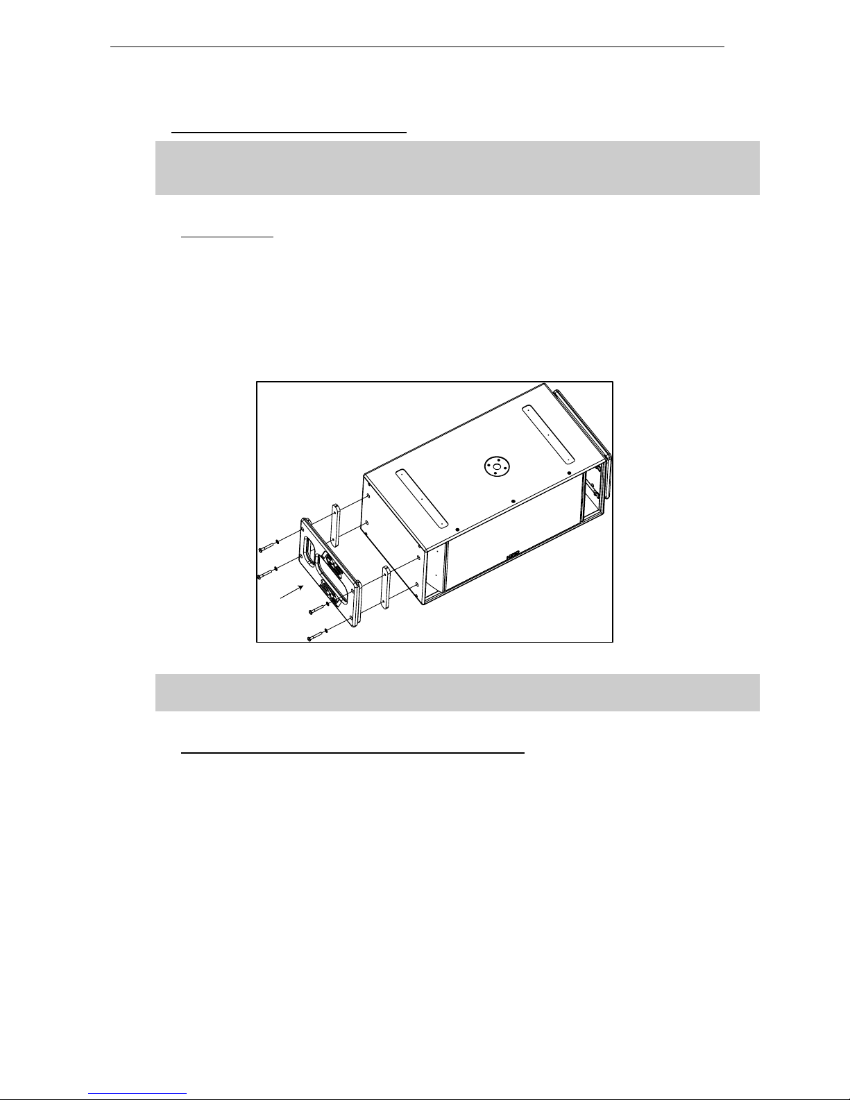
2.2.1 RS15 Handles
• Tools: TORX #50
• Remove the four screws on each side of RS15
• Fill each screw hole with Loctite 243 or equivalent;
• Position spacers and handles according to below drawing (vertical opening must be aligned with
connector panel or owner’s plate)
• Insert the four washers and screws provided with the RS15-HANDLES kit and tight them.
INSTALLING RS15 HANDLES
IMPORTANT
RS15 handles must not be used to fly RS15’s (through illegal use of straps for example)
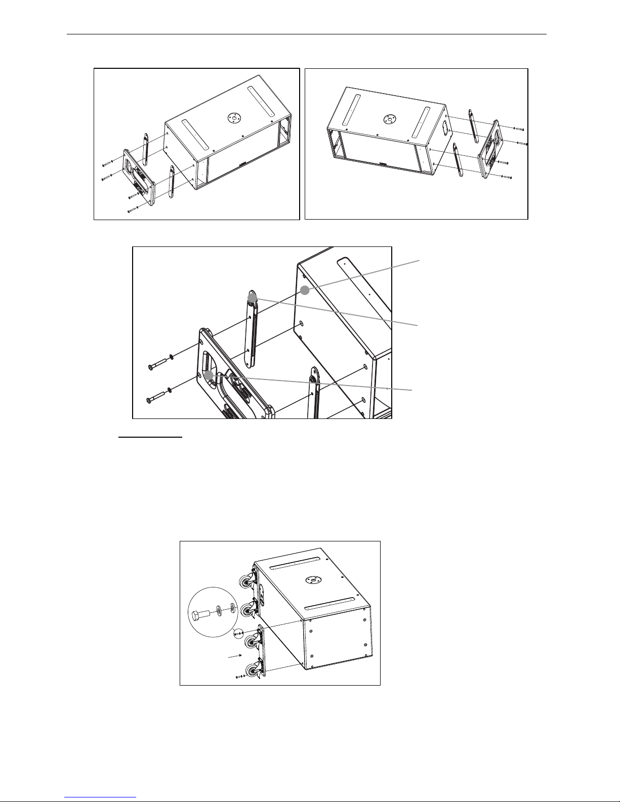
2.2.2 RS15 Flying Plates with handles (touring applications)
IMPORTANT
• Tools: TORX #50
• Remove the four screws on each side of RS15;
• Fill each screw hole with Loctite 243 or equivalent;
• Position flying bars so that articulated link bars are opposite to skids, ie at the top of the cabinet;
• Position handles according to below drawing (vertical opening must be aligned with connector
panel or owner’s plate);
• Insert the four washers and screws provided with the RS15-FLPLATES kit and tight them (torque
value must be 10 Nm minimum).
Page 12/58 RS15 GENERAL INSTRUCTIONS
INSTALLING RS15 FLYING PLATES AND HANDLES
2.2.3 RS15 Wheels
• Tools: HEXE #13
• Remove the four screws on RS15 back panel;
• Fill each screw hole with Loctite 243 or equivalent;
• Position wheels according to below drawing;
• Insert the 8 washers and 4 screws provided with the RS15-WHEEL kit (see detail in below
drawing) and tight them.
Holes to be filled
with Loctite 243
Link Bars going
upwards opposite
to skids
Vertical Openings
opposite to
loudspeakers
RS15 GENERAL INSTRUCTIONS Page 13/58
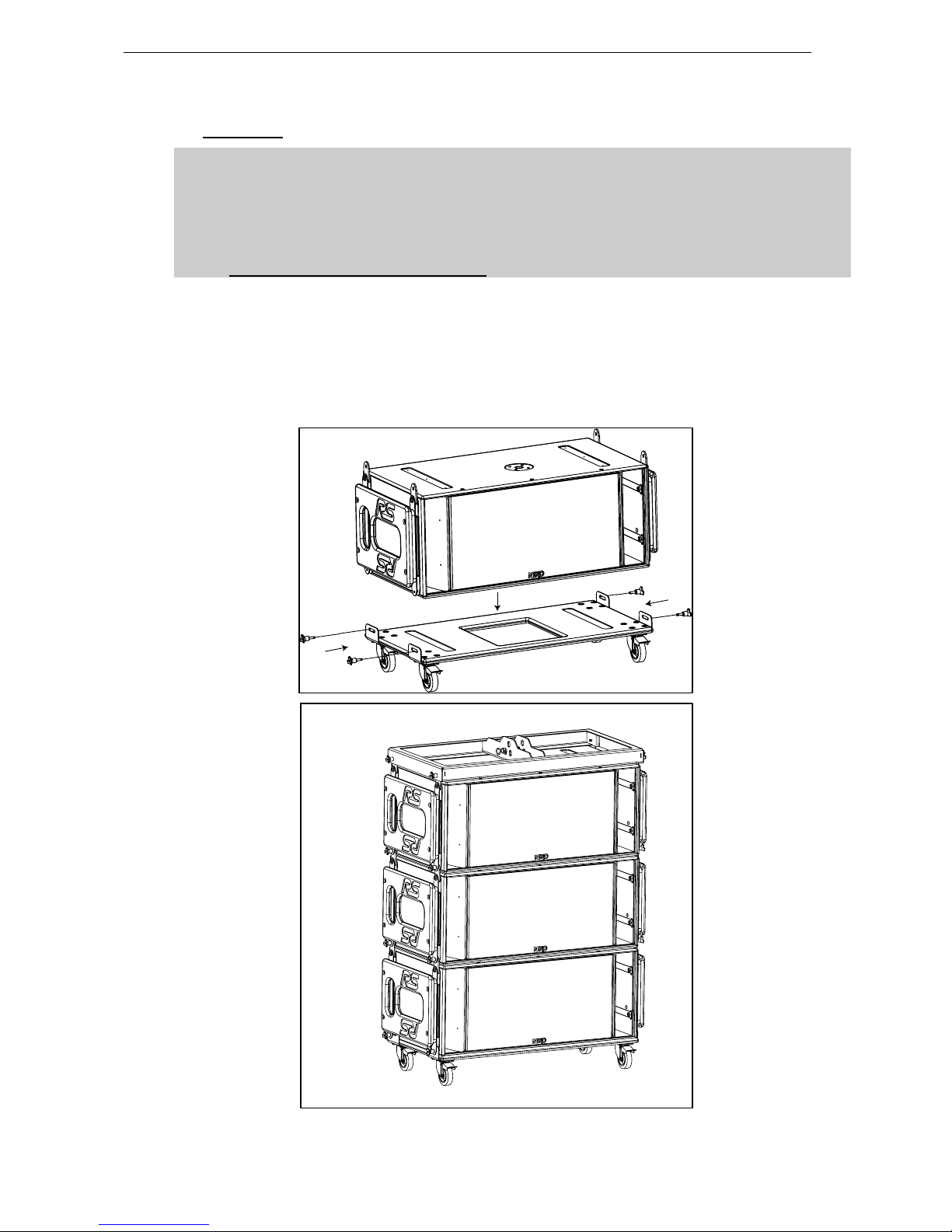
2.2.4 RS15 Dolly
IMPORTANT
1- TRANSPORTING RS15 ON DOLLY REQUIRES THAT FLYING PLATES ARE INSTALLED
ON ALL CABINETS SO THAT RS15’S CAN BE SECURED TOGETHER:
2- RS15 DOLLY IS DESIGNED FOR UP TO 3 RS15’S AND BUMPER;
NEVER EXCEED THESE QUANTITIES.
• The first RS15 must be locked to the RS15 dolly using four push-pins according to below
drawing;
• Subsequent RS15s are stacked on top using four push-pins per additional cabinet to secure the
assembly;
• Bumper is to be attached to the top cabinet.
Page 14/58 RS15 GENERAL INSTRUCTIONS
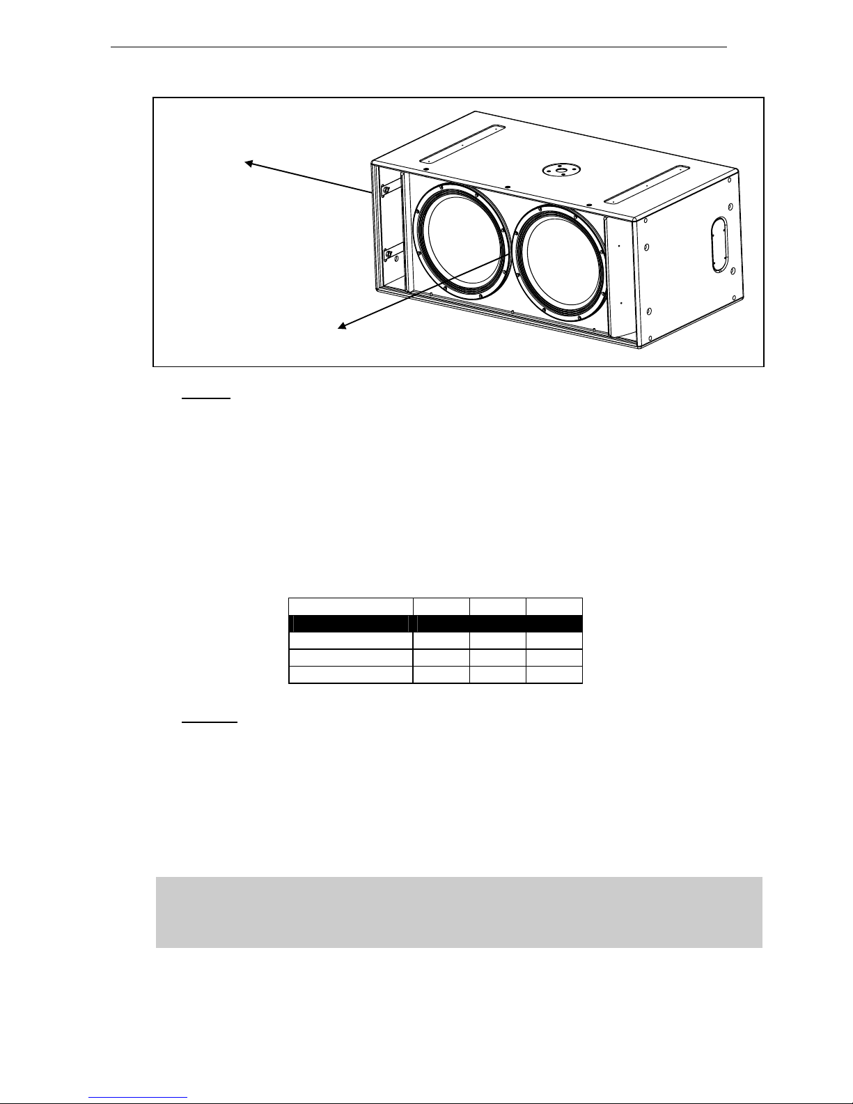
2.3 Speaker connection
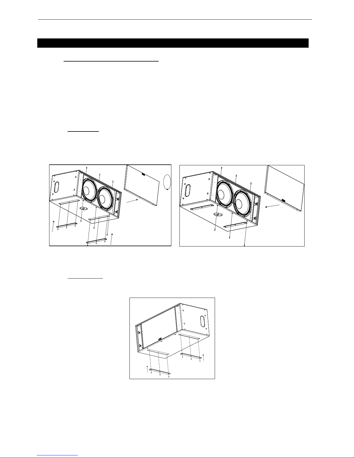
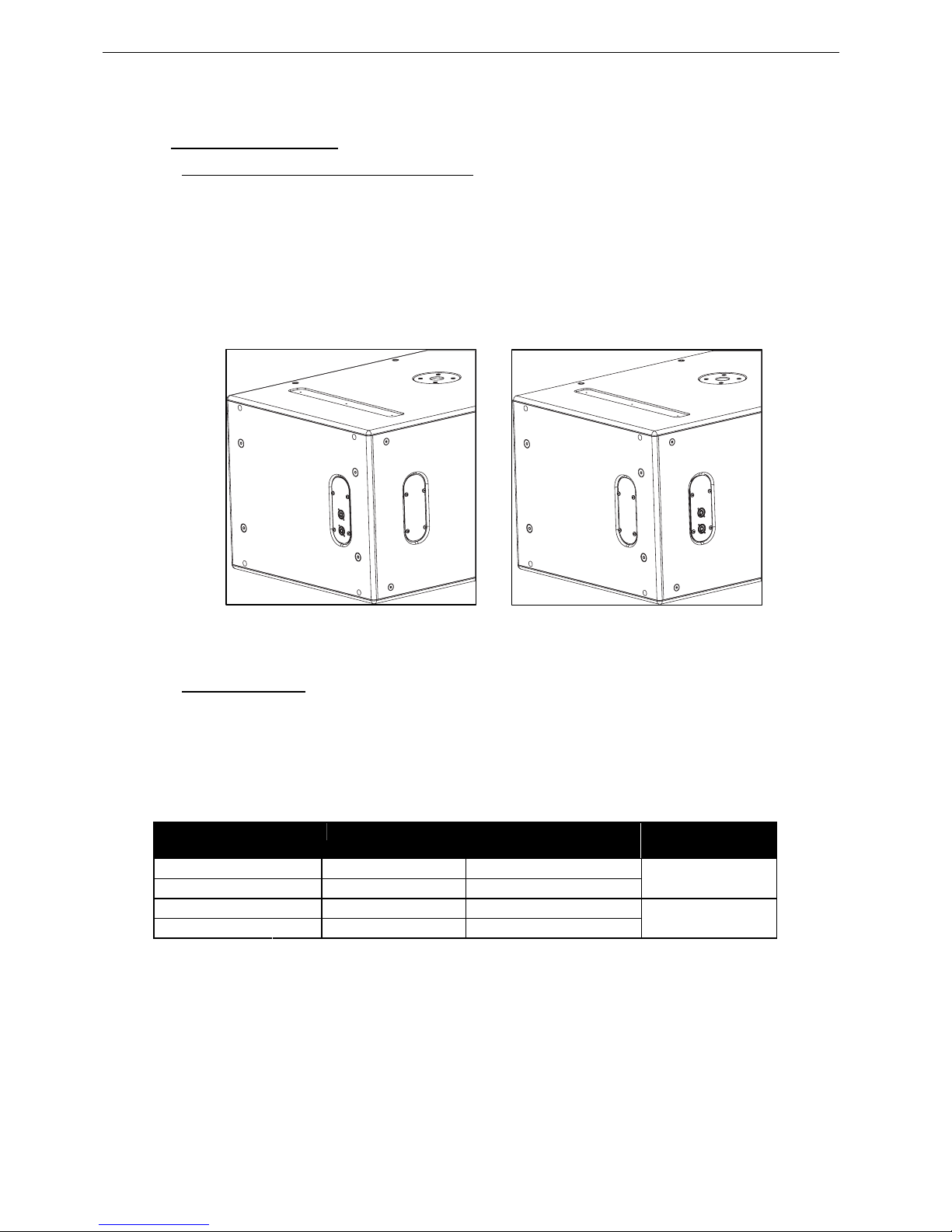
2.3.1 Configuring Connector and Owner plates
Owner and Connector plates can be exchanged depending on chosen directional configuration
Please note that the connector plate can pass through the holes, no unsoldering is therefore required.
• Directional Mode : it is recommended to install the connector panel on the side which supports
the rigging plates;
• Omni Mode: it is recommended to install the connector panel on the side opposite to the drivers
(factory default configuration)
CONNECTOR PLATE IN DIRECTIONAL MODE CONNECTOR PLATE IN OMNI MODE
2.3.2 RS15 connectors
RS15 is connected through Speakon NL4FC plugs (not supplied). A wiring diagram is printed on the
connection panel located on the back of each cabinet.
The 4 pins of the 2 Speakon sockets are connected in parallel within the enclosure.
Either connector can be used to connect an amplifier or to link to an additional RS15 cabinet.
Connectors are wired as follows:
Speakon NL4F
Connectors
Omni Mode Directional Mode Comment
1(-)
⇒
15’’ driver Right (-) 15’’ driver Rear (-)
1(+)
⇒
15’’ driver Right (+) 15’’ driver Rear (+)
Driver Next to Connector
Panel
2(-)
⇒
15’’ driver Left (-) 15’’ driver Front (-)
2(+)
⇒
15’’ driver Left (+) 15’’ driver Front (+)
Driver Opposite to
Connector Panel
RS15 GENERAL INSTRUCTIONS Page 15/58
2.3.3 Cabling
NEXO recommends the exclusive use of multi-conductor cables to connect the system: the cable kit is
compatible with all the cabinets, and there is no possible confusion between Front and Rear drivers.
Cable choice consists mainly of selecting cables of the correct sectional dimension (size) in relation to
the load resistance and the cable length. Too small a cable section will increase both its serial
resistance and its capacitance; this reduces the electrical power delivered to the loudspeaker and can
also induce response (damping factor) variations.
For a serial resistance less or equal to 4% of the load impedance (damping factor = 25), the maximum
cable length is given by:
L
max
= Z x S S in mm2, Z in Ohm, L
max
in meters
The table below indicates these values, for 3 common sizes.
Load Impedance (Ω)
2 4 8
Cable section Maximum Length (meters)
1,5 mm² (AWG #14) 3 6 12
2,5 mm² (AWG #12) 5 10 20
4 mm² (AWG #10) 8 16 32
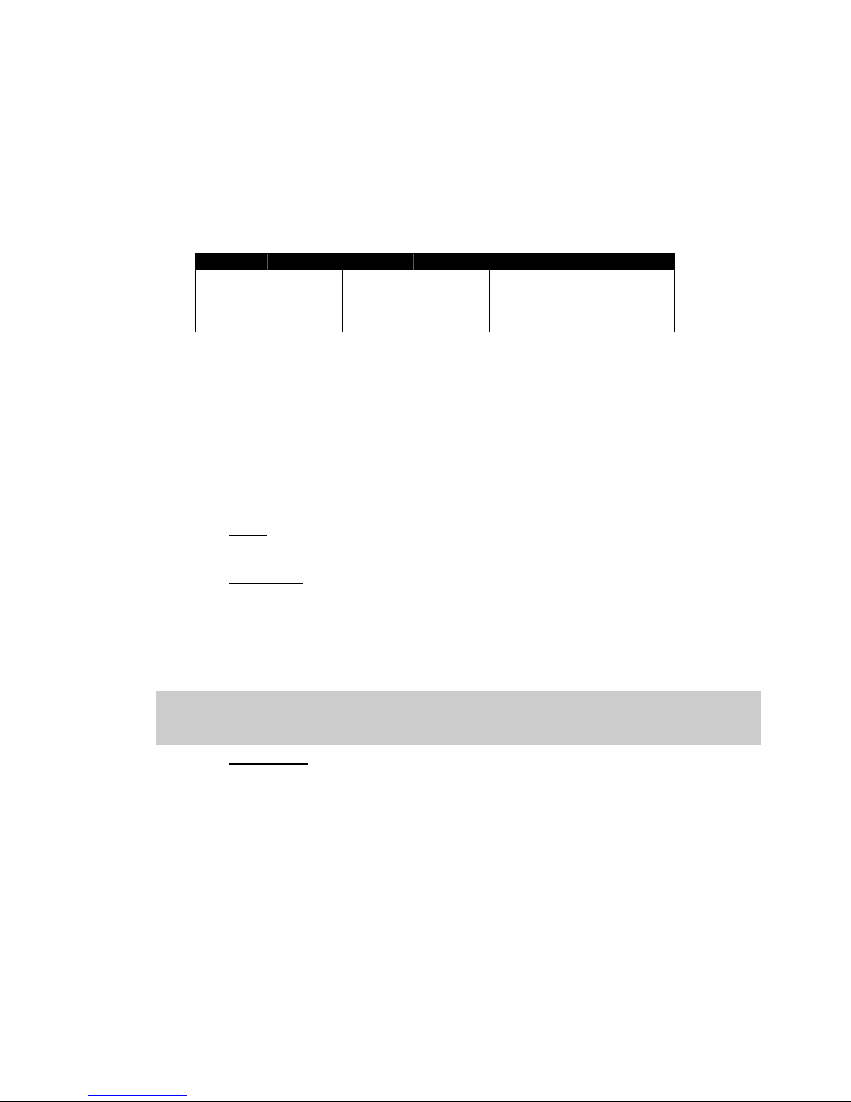
2.3.4 Example
• Each RS15 driver has a 8 Ohms nominal impedance; in omni mode, both loudspeakers can be
driven in parallel on one amplifier channel, presenting therefore a 8/2 = 4 Ohms load impedance.
The maximum acceptable 2x2.5 mm
2
(AWG #12) cable length L
max
for RS15 with its 2 drivers in
parallel is 10 meters.
• When driven in directional mode, RS15 requires 2 amplifier channels, presenting therefore two
independent 8 Ohm load impedances. The maximum acceptable 4x1.5 mm
2
(AWG #14) cable
length L
max
for RS15 with its 2 drivers driven independently is 12 meters.
IMPORTANT
Long speaker cables induce capacitive effects – up to hundreds of pF depending on the
quality of the cable - with a high-pass effect on high frequencies. If long speaker cables
must be used, ensure that they do not remain coiled while in use.
LEFT
(FRONT)
2-/2+
RIGHT
(REAR)
1-/1+
OMNI
MODE
DIRECTIONAL
MODE

Page 16/58 AMPLIFIER SELECTION FOR USE WITH RS15
3 AMPLIFIER SELECTION FOR USE WITH RS15
NEXO recommends high power amplifiers in all cases. Budget constraints are the only reason to select
lower power amplifiers. A lower power amplifier will not reduce the chances of driver damage due to
over-excursion, and may actually increase the risk of thermal damage due to sustained clipping. If an
incident occurs on an installation without protection, the fact that amplifiers only generating half their
rated output power (-3dB) are used will not change anything in respect of possible damage. This is due
to the fact that the RMS power handling of the weakest component in the system is always 6 to 10 dB
lower than the amplifier rating.
3.1 RS15 recommended amplification
RS15 is rated for very high power handling and has a 2x8 Ohms nominal impedance.
These impedance valuse allow connection of up to 4 cabinets in parallel for each amplifier channel.
Nexo recommends amplifiers in agreement with table below:
Recommended
Amplifier#
OMNI MODE DIRECTIONAL MODE
1 x RS15 2 x 700 Watts to 1200 Watts / 8 Ohms or
1 x 1400 Watts to 2400 Watts / 4 Ohms (*)
2 x 700 to 1200 Watts / 8 Ohms
2 x RS15 2 x 1400 Watts to 2400 Watts / 4 Ohms or
1 x 2800 Watts to 4800 Watts / 2 Ohms (*)
2 x 1400 Watts to 2400 Watts / 4 Ohms
4 x RS15 2 x 2800 Watts to 48000 Watts / 2 Ohms 2 x 2800 Watts to 4800 Watts / 2 Ohms
(*) driving both drivers in parallel requires dedicated speaker cable
3.1.1 Current rating
It is very important that the amplifier behaves correctly under low load conditions. A speaker system is
reactive by nature: on transient signals like music it will require four to ten times more instantaneous
current than its nominal impedance would indicate. Amplifiers are generally specified by continuous
RMS power into resistive loads; however the only useful information about current capacity is the
specification into a 2 Ohm load. It is possible to perform an amplifier listening test by loading the amps
with twice the number of cabinets considered for the application (2 speakers per channel instead of one,
4 instead of 2) and running the amps up to the onset of clipping. If the signal does not noticeably
deteriorate, the amplifier is well adapted (overheating after approximately ten minutes is normal but
thermal protection must not operate too quickly after starting this test).
3.1.2 Amplifier settings
Gain value
Gain is the key to correct alignment of the system. It is especially important to know the gain of all
amplifiers used in your set-up. The tolerance should be about ±0.5 dB. In practice this can be difficult to
achieve because:
• Some amplifier brands have an identical input sensitivity for models of different power rating (this
infers a different voltage gain for each model). For example, a range of amplifiers with different
power outputs, all having a published input sensitivity of 775mV/0dBm or 1.55V/+6dBm, will have
a wide range of actual gains – the higher the power, the greater the gain.
• Various other brands may offer constant gain but only within a given product range, for example
they may fit fixed input sensitivity only on their semi-professional amps.
• Even if a manufacturer applies the constant gain rule to all models, the value selected will not
necessarily be the same as that chosen by other manufacturers.
• Some products can exhibit manufacturing tolerances for the same model of ±1dB or more. Some
amplifiers may have been modified, possibly without any label indicating the new values. Others
may have gain switches fitted internally where it is impossible for the user to verify the actual
setting without opening the amplifier casing.
AMPLIFIER SELECTION FOR USE WITH RS15 Page 17/58
• In cases where you don't know the gain of your amplifier (or want to check it) please follow this
procedure:
1) Unplug any loudspeakers from the amplifier outputs
2) With a signal generator, feed a sine wave at 1000Hz at a known voltage (say 0.5V) to
the input of the amplifier under test
3) Measure the voltage at the output of the amplifier
4) Calculate the gain using the formula Gain = 20 * LOG
10
(Vout/Vin).
Some examples:
Vin / Gain 20dB 26dB 32dB 37dB (1.4V sensitivity / 1350Wrms)
0.1 V 1 V 2 V 4 V 7.1 V
0.5 V 5 V 10 V 20 V 35.4 V
1 V 10 V 20 V 40 V 70.8 V
Remember that constant sensitivity settings will give a different gain value when the amplifier power is
different.
NEXO recommends low gain amplifiers: +26dB is recommended, as it is at the same time adequately
low and quite common amongst amplifier manufacturers. This gain setting improves signal to noise ratio
and allows all preceding electronic equipment, including the NX242 TDcontroller or GEO S12
TDController, to operate at optimum level. Remember that using a high gain amplifier will raise the
noise floor proportionally.
Operating Mode
Most two channel amplifiers available on the pro-audio market have the following operating modes:
• Stereo:
two fully independent channels deliver identical power into identical loads
• NEXO recommends Stereo Mode for all amplifier channels feeding RS15’s.
• Bridge-Mono:
the second signal channel processes the same input as the first channel, but with
reversed phase. The (single) load is connected between the two positive channel outputs using a
suitable connection. While the total output of the amplifier remains the same, the available output
voltage, the minimum impedance that can be connected and the voltage gain are doubled as
compared with stereo operation. Typically, only channel 1 input is active. Positive and negative
output connections vary depending on amplifier manufacturers.
• NEXO does not recommend Bridge Mono Mode unless amplifier power is clearly not sufficient.
IMPORTANT
When in Bridge-Mono mode, check your amplifier user manual for proper connection of
outputs 1(+) and (2+) in relation to input phase.
• Parallel-mono: the output terminals of the two channels are configured in parallel using an
internal relay. The (single) load is connected either to the output of channel 1 or to that of channel
2 (as if in stereo). While the total output of the amplifier remains the same the output voltage level
is also the same as in stereo mode. The minimum impedance that can be connected is reduced
by half due to the fact that current capability is doubled. Typically, only channel 1 input is active.
• NEXO does not recommend Parallel-Mono Mode for RS15 amplification.
Warning on amplifiers signal processing features
Some high-end amplifiers may include signal processing functions similar to those found in the NX242
TDcontroller or in GEO S12 TDController ("loudspeaker offset integration", "limiter", "compressor," etc.).
Moreover, when this processing is digital, computation latency time can introduce a few milliseconds
delay from input to output. These functions are not adapted to specific system requirements and may
interfere with the complex protection algorithms used in the NX242.
Page 18/58 AMPLIFIER SELECTION FOR USE WITH RS15
NEXO do not advise using other protection systems in conjunction with the NX242 and they should be
disabled.
IMPORTANT
For proper system protection, no latency time or non-linear devices should be inserted
between the output of GEO S12 TDController or NX242 TDController and the input of
loudspeakers through use of DSP modules such as internal amplifier signal processing.
3.2 RS15 and NXAMP TDControllers
NEXO Powered TDControllers NXAMP 4X1 & 4X4 are integrated solutions for Control and amplification
for all NEXO speaker ranges.
NXAMP4x1 and NXAMP4x4 power capability is listed in the table below:
Mode 4 Channels Bridge Stereo
NXAMP4x1 4 x 650 Watts / 8 Ohms
4 x 900 Watts / 4 Ohms
4 x 1300 Watts / 2 Ohms
2 x 1800 Watts / 8 Ohms
2 x 2600 Watts / 4 Ohms
NXAMP4x4 4 x 1900 Watts / 8 Ohms
4 x 3400 Watts / 4 Ohms
4 x 4000 Watts / 2 Ohms
2 x 6800 Watts / 8 Ohms
2 x 8000 Watts / 4 Ohms
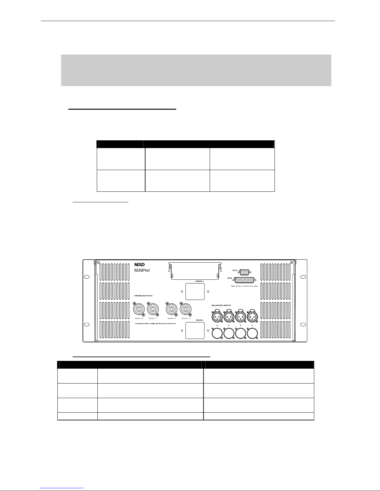
3.2.1 NXAMP connectors
NXAMP4x1 and NXAMP4x4 rear panels feature:
• 4 analog inputs / outputs (links) on XLR3 connectors;
• 4 digital inputs / outputs on RJ45 connectors with optional card;
• 4 speaker level outputs on NL4FC connectors.
Figure below shows connectors implementation on the rear panel.
3.2.2 RS15 and NXAMP recommended configurations
OMNI MODE DIRECTIONAL MODE
1 x RS15 1 channel of NXAMP4x1 in Bridge Stereo Mode 2 channels of NXAMP4x1 in 4 channels Mode
2 channels of NXAMP4x1 in Bridge Stereo Mode
2 x RS15 2 channels of NXAMP4x1 in Bridge Stereo Mode
1 channel of NXAMP4x4 in 4 channels mode
2 channels of NXAMP4x1 in Bridge Stereo Mode
2 channels of NXAMP4x4 in 4 channels mode
4 x RS15 2 channels of NXAMP4x4 in 4 channels mode
2 channels of NXAMP4x4 in 4 channels mode
8 x RS15 4 channels of NXAMP4x4 in 4 channels mode 4 channels of NXAMP4x4 in 4 channels mode
 Loading...