

Nexo PS8U User Manual
NEXO S.A.
154 allée des Erables
ZAC de PARIS NORD II B.P. 50107
F-95950 Roissy CDG CEDEX
France
Tél: +33 1 48 63 19 14
Fax: +33 1 48 63 24 61
eMail: info@nexo.fr
Americas
NEXO USA, Inc
2165 Francisco Blvd. East
Suite E2
San Rafael, CA 94901-5522
USA
Tel: +1 415 482 6600
Fax: +1 415 482 6110
eMail: info@nexo.cc
Latin America
NEXO LatAM
Hualfin 1054
1424 Capital Federal
Argentina
Tel +54 114 432 1911
www.nexo-sa.com
LIMITED WARRANTY
NEXO loudspeakers and electronics are covered against defects in workmanship or materials for a period of two (2) years from the original date of purchase. At the option of NEXO the defective item will
be repaired/replaced with no charge for materials/labour. The item is to be adequately packaged and dispatched, pre-paid, to a NEXO authorised distributor/service centre. Unauthorised repair shall void
the warranty. The NEXO warranty does not cover cosmetics or finish and does not apply to any items which in NEXO’s opinion have failed due to used abuse, accidents, modifications or any type of misuse.
All images and text herein are the property of NEXO SA, and deemed accurate, although specifications are subject to change without notice.
v1.5
Nexo PS MasterNoTab.QXD 12/7/05 12:12 pm Page 24
www.nexo-sa.com
50˚
100˚
+25 ˚
-30˚
100˚
50˚
+
30
˚
-
25
˚
2
3
INTEGRATED SYSTEM SPECIALISTS
Since the 1970s, NEXO has been a global leader
in research and development of loudspeaker and
complete sound reinforcement systems. Our
expertise focuses on integrated signal processing,
intelligent amplification, innovative transducer
and waveguide designs, enclosure materials and
hardware. While audio components designed in
isolation may individually achieve high
performance, making them work together often
requires time-consuming setup and delicate
adjustments. This is why we engineer all PS
system elements to function as an ensemble,
where the whole is even greater than the sum of
exceptional parts. The results yield unsurpassed
performance and reliability.
We apply specialized test and
measurement tools along with unique ideas to
the challenges of sound reinforcement, creating
a range of systems that are simple and easy to
use, while satisfying the most critical listeners.
Servo-controlled signal processing
driven by amplifier output monitoring is a
central element of NEXO systems. VCAs and
VCEQs instantaneously respond to amplifier
voltage and current via multiple time constants
and signal integration algorithms that model
multiple electroacoustic complexities including
voice coil temperature and power compression.
TDcontrollers (TD=Temperature Displacement)
also apply internal models of transducer
characteristics as failsafe protection. Whether
analogue, or digital, our advanced loudspeaker
system processors insure accurate reproduction
at extreme output levels.
THE ASYMMETRICAL ADVANTAGE
NEXO PS Series’ exceptional performance is
achieved by advanced system integration and
anchored by our Asymmetrical Dispersion
Constant Directivity horn design. As the
signature physical design feature in PS
systems, our asymmetrical horns are engineered
so that vertical coverage is narrower above horn
axis (+25°) than below (-30°), while horizontal
coverage is narrower above horn axis (50°
Horizontal for +25°Vertical) and wider below
(100°Horizontal for -30° Vertical). (see Figures
#1 and #2)
The obvious sonic benefits to this
asymmetrical coverage are that, when properly
used, PS systems significantly reduce the
amount of ambient, reverberant energy caused
when loudspeakers misdirect their output
towards walls and ceilings. In practice, this
means that PS Series asymmetrical horns allow
users to directly focus more loudspeaker output
on the audience, or performers (in monitor
applications), and less loudspeaker output
everywhere else.
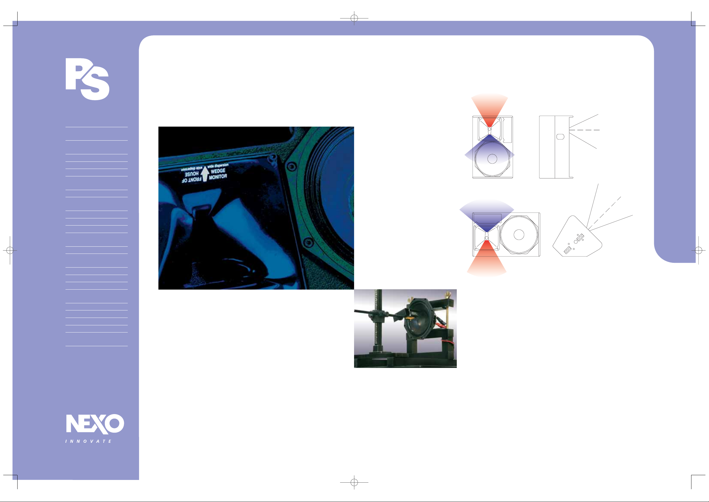
A sticker on the wide dispersion side of
the PS horn indicates the correct orientation for
Front of House (FOH) and wedge monitoring
applications. (see figures on pg #2) The arrow
indicates the “wide side” of PS horn dispersion.
Users simply need to position the arrow so that it
points in the direction needing widest coverage
and away from the direction needing the
narrowest coverage.
CONTENTS
NEXO and the Evolution
of PS Series Systems 2
Introduction to PS 8,
PS10 & PS15 3
Coverage & Controllers 4
PS Series Rigging & Flying 5
PS8 Loudspeaker 6
PS8 Architectural &
Engineering Specs 7
LS400 Sub-Bass 8
LS400 Architectural &
Engineering Specs 9
PS8 Amplifier 10
PS8 TDcontroller 11
PS10 Loudspeaker 12
PS10 Architectural &
Engineering Specs 13
LS500 Sub-Bass 14
LS500 Architectural &
Engineering Specs 15
PS10 TDcontroller 16
PS10 Amplifier 17
PS15 Loudspeaker 18
PS15 Architectural &
Engineering Specs 19
LS1200 Sub-Bass 20
PS15 Bass 21
PS15 TDcontroller Mk II 22
NX242 TDcontroller 23
NEXO Contact Data, Website
Address & NEXO Warranty 24
NEXO’s PS Series incorporates
breakthrough designs in both
asymmetrical constant directivity horns
and integrated electronics. The results
are three scaleable and easily configured
systems, which provide exceptional
performance in any application where
small, high output, linear response
loudspeakers are required.
PS Series systems can be used as floor
monitors or stand-mounted main PA
speakers, or flown as side and rear fill
coverage speakers with GEO and Alpha
System. PS systems can be installed
vertically or horizontally as main PA or
distributed/fill coverage speakers. Our
attention to the smallest sonic detail, no
matter your intended application, makes
the PS Series Systems the perfect sound
reinforcement solution.
UNCOMPROMISING ENGINEERING,
ATTENTION TO DETAIL
NEXO S.A.
Now in its fourth decade, NEXO’s company mission is
to provide wide-ranging solutions that enhance the
science, art and commerce of sound reinforcement.
Founded by Michael Johnson, NEXO’s Managing
Director, and Chairman/R&D Director Eric Vincenot,
NEXO became a publicly traded company in May
2001. NEXO shares are listed on the Marche Libre of
the Paris Bourse (SICOVAM 4441).
The added access to capital markets
gained by this public offering strengthened NEXO’s
ability to pursue aggressively genuine audio
innovations. The first of these advanced audio
design options is the widely heralded GEO Tangent
technology, which incorporates several fundamental
wave-source patents.
NEXO’s sound reinforcement systems also
include the compact, versatile PS Series plus the
high performance Alpha System and AlphaeSeries. In
short, all NEXO loudspeakers, analogue and digital
controllers, power amplification, and advanced
rigging systems are designed to deliver: Sonic
Innovation That Works. NEXO is a world leader in the
design and manufacture of loudspeaker systems for
sound reinforcement.
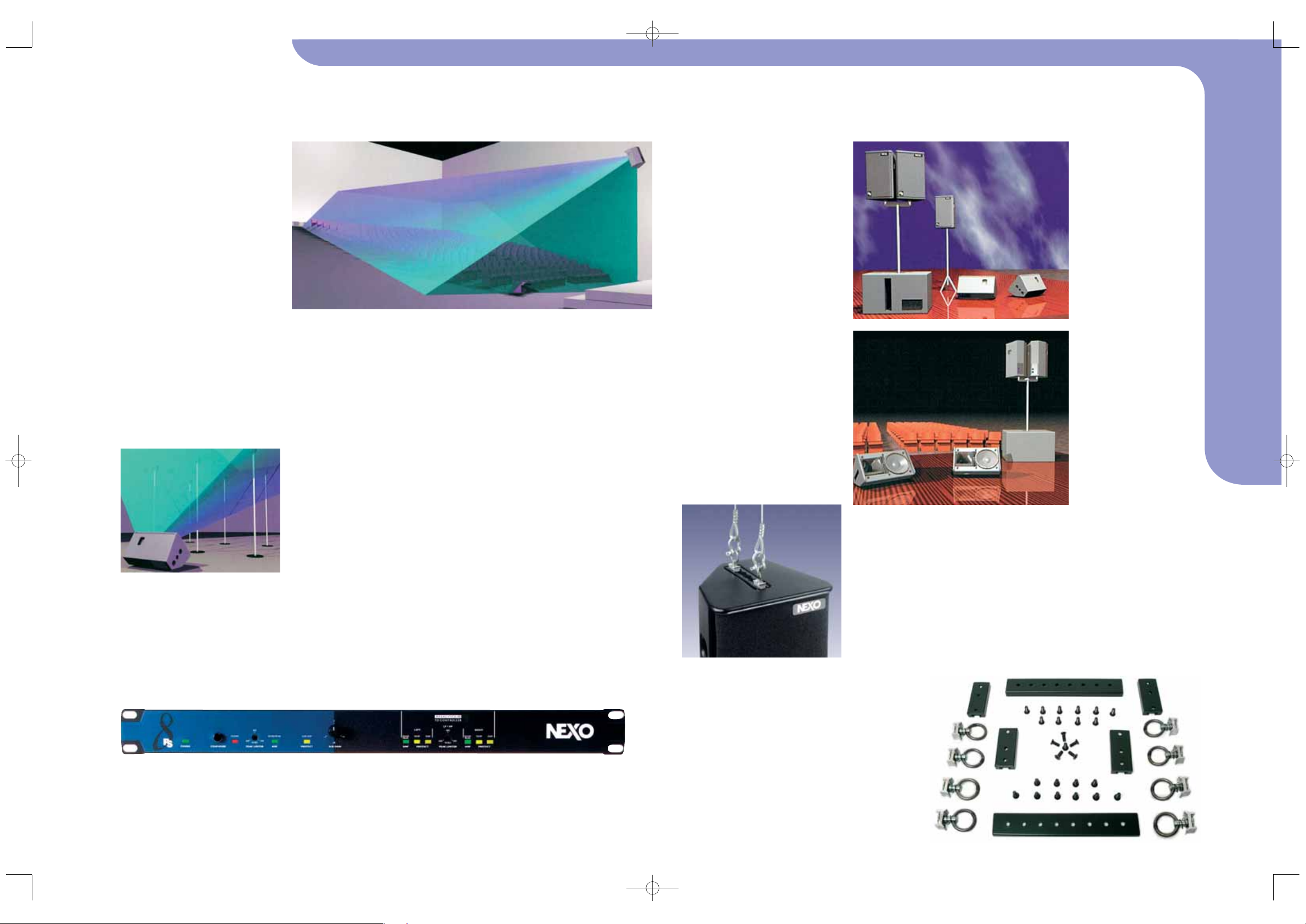
Figure #2: In stage monitor
mode, with horn rotated
180° from Figure #1, the
PS loudspeaker displays
100° horizontal coverage
at 30° above the centreline
and narrows to 50°
horizontal coverage, at 25°
below the centreline.
Figure #1: In this
conventional FOH
configuration, the PS Series
loudspeaker yields 50°
horizontal coverage at 25°
above the centreline,
expanding to 100°horizontal
coverage at 30°below the
centreline, so that coverage
widens with distance.
Figure #1
Figure #2:
Above: Laser scanning
equipment helps evaluate
cone transducers such as the
neodymium PS8 woofer.
Nexo PS MasterNoTab.QXD 12/7/05 12:12 pm Page 2
4
5
For mobile system designs, our
asymmetrical horn design allows users to
quickly change horn coverage according
to need. The specific dispersion of PS8,
PS10 & PS15 horns can be seen on Figure
#1 ("FOH" configuration). Access to any PS
horn for inspection and configuration is
easily made by removing the front grille
with a gentle pull on the sides of the grille
to disconnect the press-stud fixings.
To modify horn orientation, remove the
four Allen 4 metric or TORX TX25 screws
(depending on model and age of the
cabinet) that secure the horn.
FRONT-OF-HOUSE CONFIGURA TION
Good coverage of audiences often requires a
conflicting combination of wide coverage (“shortthrow”) for the closest listeners (below cabinet
axis) and narrow coverage (“long-throw”) for
distant areas (on or above axis). The PS Series
horizontal horn coverage varies from “shortthrow” to “long-throw” along the vertical axis to
match precisely these practical single system
requirements. In most applications, asymmetrical
horns should be used with the “wide” dispersion
side directed towards the floor (as referenced by
the arrow), but any of the four various horn
orientations are usable, depending on venue
geometry and room acoustics (see Figure #1).
STAGE MONITORS
For stage monitors, the best coverage must be
wider when performers are closest to the wedge,
and above the horn axis, than when they move
away from the wedge and below the horn axis
(see Figure #2). The flexibility to be deployed in
this manner is one major reason why PS Series
loudspeakers are widely used in floor monitor
applications.
In this configuration, the PS horn must
be rotated so that its “wide side” dispersion is
in “wedge” position and that the directional
arrow is pointed towards the top of the
horizontally-oriented cabinet. This monitorfriendly dispersion combines with the PS Series’
exceptional power handling to yield unrivalled
foldback/monitor performance.
PS SERIES TD CONTROLLERS
Equalization and Subsonic/VHF Filtering
Because all PS cabinets are acoustically
designed for maximum efficiency, each TD
Controller applies strategic equalization
corrections to insure proper tonal balance and
system response. This active equalization also
extends PS Systems’ bandwidth, especially at
low frequencies where acoustical output is
limited by cabinet size. Active, rather than
passive, attenuation allows amplifier voltages to
be lowered for a specific output SPL, and
functionally increase the maximum possible SPL
from any PS amplifier.
Low and high-pass filters are used to
remove signals out of the usable frequency
range, eliminating sub and ultra-sonic
components that could potentially degrade the
performance of the Controller and amplifiers.
These filters are optimized to realize the overall
target system response.
PS/LSub Crossover and Servo Control
From input signals summed together, the
resulting mono signal is low-pass filtered to feed
the Sub-bass channel. When the channel
VCAS, VCEQS AND AMPLIFIERS
Each of the three Audio channels (Left, Right
and Sub-bass) contains two voltage-controlled
elements driven by servo signals. The PS8Amp
and PS10Amp are power amplifiers tailored for
PS8 and PS10 systems and their respective
LS400 & LS500 sub-bass requirements.
The identical structure and power ofthese
3RU devices offers two or three-channel
instantaneous configuration via front-panel switch,
allowing 3-way use with the appropriate NEXO
SubBass or a wideband (2-way) configuration.
Power delivered by the amplifier is thus
optimized for the proper configuration. All
connections and controls are located on the front
panel including mains fuses and voltage
selection. Speaker wiring of each cabinet is
automatically re-assigned.
PS SERIES RIGGING AND FLYING
PS8, PS10 and PS15 have a built-in 35mm (1
3/8in) diameter stand adapter. Cabinets can be
positioned directly on a general-purpose speaker
stand or mast inserted in top-fitted stand
adapters on LS400, LS500 & LS1200 models. A
U-Coupler accessory allows relative rotation of
two side-by-side cabinets on top of the mast or
on a speaker stand. PS8 and PS10 mast and Ucouplers are optional. For safety reasons,
U-coupler use is not recommended with PS15
cabinets (see Figures #1, & #2).
PS10 & PS15 FLYING RAILS & RINGS
PS10s and PS15s ship with steel anchor plates
intended for these optional fittings:
■ T op: 6-position aircraft-flying rail. (9 for PS15)
■ Bottom: T win single-position round aircraft
flying rails, or two 3-position aircraft flying
rails for the PS15. These rails are supplied with
optional flying kits containing all necessary
screws and four single stud aircraft flying
rings. Heavy-duty double stud flying rings can
be used in all rails except on the PS10 bottom.
Vertical orientation of cabinets is a function of
top-rail ring position. For safety reasons two
rings must be linked, per rail, to two
independently fixed straps.
PS10 OMNIMOUNT® STYLE CLAMPS
The back and bottom of the PS10 is equipped
with internal M8 metric anchor points for
Omnimount100 Series standard spacing. This is
particularly convenient for permanently installed
cabinets. Original screw removal requires a N°4
metric Allen key/TORX25.
PS8 ACCESSORIES
There are three PS8 mounting accessories. The
FS0081-001 is intended for direct mounting onto
the PS8 cabinet surface. It provides two M10
captive nuts that allow these three accessories
to be fitted:
COVERAGE
ACCORDING TO
NEED
Figure #2: (Above) With
horn rotated 180° from
Figure #1, this monitor
application provides a
wide (100°) sweet spot for
the performer’s listening
zones, and restricts
unwanted below-the-belt
coverage.
Figure #1: (Above)
Computer representation
of how the PS Series’
asymmetrical horns match
pattern control to the
seating area of a typical
rectangular venue.
Photo #3 (right): The
PS15 (accessory) rigging
kit, part # FLYPS15
Photo #1: The PS8
TDcontroller
Figure #1(left): PS Series
stage rigging facing Front
of House.
Figure #2 (below left):
PS Series rigging from the
Performer’s perspective.
Photo #2 (Above left):
Installed, flown
PS10
Loudspeaker
■ Standard lighting hook/CLAMP
■ M10 lifting eye bolt
■ DIN Pivot (TV spigot)
The FS0081-002, which must be used with the
FS0081-001, provides two welded M5 nuts and
one welded M10 nut. This adapter allows the
cabinet to be fixed on the wall, ceiling, or on a
stand using the FS0081-003.
The FS0081-003 allows for Horizontal
Cabinet mounting on a stand or a 35mm mast. It
can be used with other accessories or fitted
directly to the cabinet.
configuration is set to Xover, the L&R main
channel's high-pass filters are switched to
bandpass (filter) signal components below the
crossover frequency. Slopes and other filter
characteristics are optimized using techniques
optimized for the each driver’s specific
acoustical data.
Nexo PS MasterNoTab.QXD 12/7/05 12:12 pm Page 4
www.nexo-sa.com
6
7
PS8 ARCHITECT & ENGINEERING SPECIFICATIONS
The 2-way full range loudspeaker system shall have one 8" shielded, neodymium cone transducer and a 1"-exit shielded
neodymium driver on a low distortion constant directivity asymmetrical dispersion horn. Horizontal dispersion shall range from
50° to 100° and vertical dispersion shall be +25°/-30°. Users shall be able to rotate the horn in 4x directions, in 90°
increments, as required by the application. The system shall have a Q of 10 and a Directivity Index of 10dB (nominal) at
frequencies above 1.8kHz. The system shall have a nominal sensitivity of 96dB (94dB wideband). When driven by a NEXO
PS8AMP, or by a NEXO PS8 TDcontroller properly connected to amplification capable of delivering 200 to 500Watts into an 8ø
load, the system shall produce 122 to 125dB peak SPL with a frequency response of 69Hz to 19kHz ±3dB (62Hz to 2kHz ±6dB).
The system shall have an internal passive crossover. Electrical connections shall be made via 2x SPEAKON NL4MP 4-pole
connectors.The system shall weigh 7.5kg(16.5lbs), have a tuned ported multi-angle enclosure constructed of 18ply Baltic birch
and be finished in structured black coating with exterior dimensions no greater than 406mmH x 250mmW x 219mmD (159.8" x
98.4" x 86.2"). Exterior hardware shall include 3x threaded mounting points (2x on top, 1x on bottom), 6x threaded mounting
points on sides, and 1-pole socket. Interior components shall be protected by a powder coated perforated steel grille. The full
range system shall be the NEXO PS8 with a NEXO PS8 TDcontroller, or NEXO NX242 Digital TDcontroller, or a NEXO PS8AMP. Other
integrated loudspeaker/controller systems shall be acceptable, provided independent laboratory test results verify these
specifications are equalled or exceeded.
PRODUCT FEATURES
■ High-power system (125dB Peak SPL @ 1m) with
new 8in LF and 1in HF low magnetic emission
Neodymium drivers for light weight (7.5kg, 16.5lbs)
and negligible magnetic leakage.
■ Rotatable, asymmetrical horn and unique cabinet
architecture ensure versatility; user-adaptable for
both PA and stage monitoring applications.
■ T wo-way passive 8Ωdesign uses a single amplifier
channel for simpler installation and lower cost.
■ Sophisticated control electronics ensure reliable,
linear operation. Supported with a full range of
mounting and flying accessories.
PS8 SYSTEM APPLICATIONS
■ Installed PA for clubs, A/V , theatre, broadcast,
Houses of Worship, theme parks, etc.
■ High-quality, low-profile stage monitoring for
clubs, A/V, theatre, broadcast, etc.
■ Near-field, down-fill and under-balcony systems
in support of larger, touring NEXO PS/Alpha systems.
■ Foreground and background music source for
retail establishments seeking audio with impact.
■ Anywhere powerful, high-quality performance is
required adjacent to magnetically-sensitive video
equipment.
This flexibility is realized by a proprietary constant
directivity asymmetrical dispersion horn, easily
configurable (by users) in four positions by 90°
rotations. Coupled with the horn’s unique
progressive horizontal (50°to 100°) and vertical
(55°) dispersion, the most suitable pattern can be
selected for vertical or horizontal PA usage or
wedge monitoring. The PS8’s 2-way passive 8Ω
design employs a single amplifier channel to
deliver bi-amped performance for less money,
space and complexity.
The PS8 Loudspeaker System is the
smallest member of NEXO’s acclaimed PS Series.
Versatile and compact, while offering full-range
output, PS8 loudspeakers are tailored for a wide
range of touring and fixed sound reinforcement
applications. Like all NEXO products, the PS8
Loudspeaker, and optional LS400 Subwoofer, are
designed to work with advanced electronic
processors, guaranteeing the highest standards
of consistent performance and reliability.
PS8 LOUDSPEAKER
PS8 Loudspeakers are magnetically shielded
and feature advanced NEXO-designed
Neodymium drivers. As such, the PS8 is
extremely light and compact, and popular with
professional's for use with magnetically
sensitive professional video or computer
equipment. The dispersion, architecture and
weight balance of the PS8 Loudspeaker are
designed to provide exceptional PA/stage
monitor performance from a single product
without compromise. Background and
foreground music playback applications are
equally well-served by the PS8 system.
PS8 LOUDSPEAKER PRODUCT FEATURES
Components LF 1x 8" (20cm) Shielded Neodymium 8Ωdriver
HF 1x 1" Shielded Neodymium throat driver + Low Distortion, Constant Directivity
Asymmetrical Dispersion Horn.
Height x Width x Depth 406 x 250 x 219mm (16"x 97/8"x 55/8")
Weight 7.5kg(16.5lbs)
Connectors 2x NL4MP 4-pole SPEAKON
Construction Baltic Birch Ply finished with textured, polyurethane black coating
Fittings Handles - Front finish: Perforated steel grille
Flying Points & Fixed Installation Threaded inserts are fitted as standard to all cabinet
surfaces for connection of mounting accessories
Stand fittings Built-in Stand Fitting, 35mm(1"3/8)
SYSTEM SPECIFICATIONS PS8 with PS8 TDcontroller
Frequency Response [a] 69Hz - 19kHz ±3dB (43Hz - 19kHz ±3dB with LS400 Subwoofer)
Usable Range @-6dB [a] 62Hz – 20kHz (40Hz – 20kHz with LS400 Subwoofer)
Sensitivity 1W @ 1m [b] 96dB SPL Nominal - 94dB SPL Wideband
Nominal Peak SPL @ 1m [b] 122 to 125dB Peak (for 200 to 500W RMS Amp.)
HF Dispersion [c] 50°to 100°Hor. x 55°V ert. Rotatable Horn, 4 positions
Directivity Q & DI [c] Q : 10 Nominal DI : 10dB Nominal ( f > 1.8kHz )
Crossover Frequencies 2.5kHz Passive
Nominal Impedance 8Ω
Recommended Amplifiers 200 to 500Watts into 8Ω for 1x PS8; 400 to 1000Watts into 4Ωfor
2x PS8 per channel
SYSTEM OPERATION
Electronic Controller The PS8 Loudspeaker must be used with a NEXO Controller (PS8 TD analogue, NX242
digital or PS8AMP integrated power amplifier). Use without a properly-connected
Controller will result in poor sound quality and may damage the components.
Dispersion configuration After removing the quick-release front grille, the HF Horn can be rotated to one of 4
positions for dispersion configuration.
Sub-bass The PS8 Loudspeaker can be used with or without the optional LS400 Subwoofer. Active
two-way operation with the LS400 is included in the PS8TD, NX242 or PS8AMP . One LS400
matches 2 x PS8, additional LS400 may be used for enhanced effect.
Speaker Cables The PS8 is wired 2- & 2+ on Speakon connectors, LS400 on 1- & 1+. Loop through
Speakons are present on both products. Single identical cables can thus be used to loop
through combinations of up to 2x PS8 & 1 x LS400 in no particular order.
SHIPPING & ORDERING
Packaging PS8s are packaged as pairs with or without PS8 TDcontroller in a single box.
Shipping Weight & Volume 2x PS.8U = 16kg(35.3lbs) 0.109cu m (3.85cu ft).
2x PS.8U + 1x PS.8UTD = 19kg (6.61lbs) 0.109cu m (3.85cu ft).
Accessories: A full selection of mounting accessories is available, please contact your Nexo Agent for details.
As part of a policy of continual improvement, NEXO reserves the right to change specifications without notice. [a] Response curves &
data : Anechoic Far Field above 300Hz, Half-Space radiation below 300Hz. [b] Sensitivity & Peak SPL data : these will depend on spectral
distribution and crest factor of program material. Measured with band limited Pink Noise. Nominal refers to Voice Decade (300Hz 3kHz), Wideband to the specified ±3dB range. Data are for speaker + processor + recommended amplifier combinations. Peak SPL is at
clipping of recommended amplifier. [c] Directivity curves & data : obtained by computer treatment on off axis response curves.
NEXO PS8 SYSTEM
>PS8 Loudspeaker
LS400 Sub-Bass
PS8 TDcontroller
PS8 Amplifier
PS8 system’s compact size, exceptional
sound and reconfigurable, asymmetrical
horn make it the perfect solution for
nearly every nearfield application.
Nexo PS MasterNoTab.QXD 12/7/05 12:12 pm Page 6
120
60
0
60
120
100 1k 10k
PS8 horizontal Off-Axis Response
10
HORIZONTAL COVERAGE (°)
ON-AXIS RESPONSE (dB)
120
60
0
60
120
100 1k 10k
PS8 Vertical Off-Axis Response
64
VERTICAL PLANE COVERAGE (°)
PS8 IMPEDANCE (Ohm)
<-24dB
-24 /-18 dB
-18 /-12 dB
-12 /-6 dB
-6 / -3 dB
-3 / 0 dB
30°
219mm [8.62"]
250mm [9.84"]
45°
250mm [9.84"]
0
10
20
30
On-Axis Responses PS8 & PS8 + LS400.
100 1k 10k
32
16
8
4
30 100 1k 10k
PS8 Impedance
406mm [16"]
www.nexo-sa.com
 Loading...