


PS Series
PS SeriesPS Series
PS Series
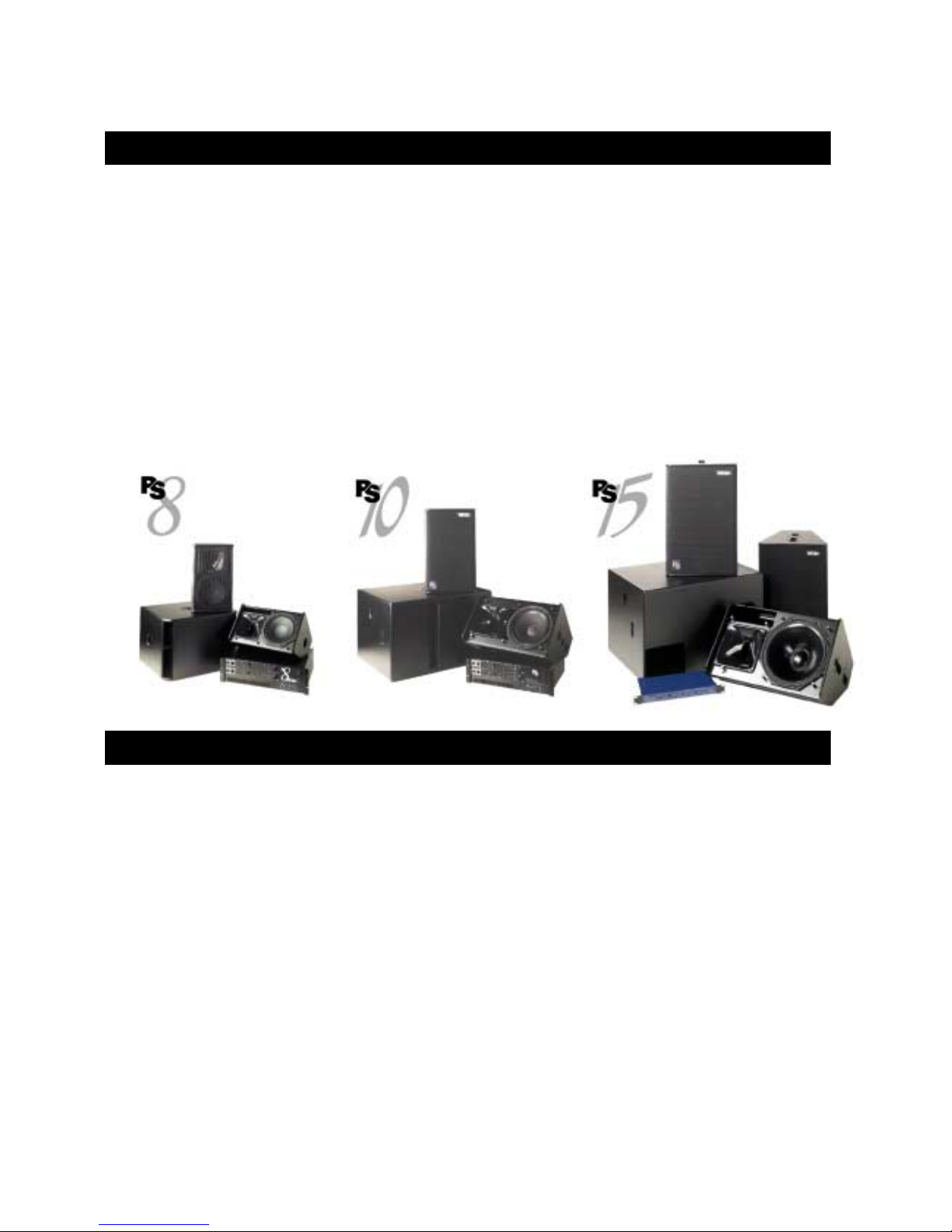
PS8 - PS8TD - LS400 - PS8Amp
PS10 - PS10TD - LS500 - PS10Amp
PS15 - PS15Bass - PS15TDMK2 - LS1200
User Manual

___________________________________________________________________________________________________
P.2
Norms: TDcontrollers
Norms: TDcontrollersNorms: TDcontrollers
Norms: TDcontrollers
Those equipments have been tested and f ound to comply with the following European and
international Standards for electromagnetic Compatibility and electrical Safety:
• Electrical safety CEI65
• Radiated & conduction emission EN55022: Information technology equipment. Radio disturbance
characteristics. Limits and methods of measurement.
Norms
NormsNorms
Norms: PSAmps
: PSAmps: PSAmps
: PSAmps
This equipment has been tested and found to comply with the following European and
international Standards for electromagnetic Compatibility and electrical Safety:
• Electrical safety CEI65
• EN55013 (emission) Limits and methods of measurement of radio disturbance characteristics of
broadcast receivers and associated equipment.
• EN55020 Electromagnetic immunity of broadcast receivers and associated equipment..
• EN60555-2 Disturbances in supply systems caused by household appliances and similar electrical
equipment. Part 2 : harmonics
• EN 50082-1 Electrom agnetic compatibility. Generic immunity standard. Part 1 : residential, c ommercial
and light industry.
Norms: All PS cabinet & L
Norms: All PS cabinet & LNorms: All PS cabinet & L
Norms: All PS cabinet & LS cabinets
S cabinetsS cabinets
S cabinets
All cabinet described in this manual as passive components are found to comply with
the following European and international Standards for electromagnetic
Compatibility
• EN50081-1: Electromagnetic com patibility. Generic emission standard. Part 1 : residential, commercial
and light industry.
• EN50082-1 : Electrom agnetic compatibility. Generic imm unity standard. Part 1 : residential, comm ercial
and light industry.
Safety Warning concerning TDcontrollers
Safety Warning concerning TDcontrollersSafety Warning concerning TDcontrollers
Safety Warning concerning TDcontrollers
This unit is fitted with 3-pin IEC standard power socket. For safety reasons the earth should not be
disconnected.
To prevent shock or f ire hazard, do not expose the unit to rain or m oistur e. To avoid electr ical shock , do
not remove covers. Dangerous voltages exist inside. Refer servicing to qualified personnel only
PS series User Manual
Revision: 2.01
Date: 05/02/2001

___________________________________________________________________________________________________
P.
3
INTRODUCTION................................................................................................................................................................ 4
LOUDSPEAKERS............................................................................................................................................................... 4
GENERAL SETUP INSTRUCTIONS.......................................................................................................................................... 4
ASYMMETRICAL HORN CONFIGURATION............................................................................................................................ 7
ACTIVE / PASSIVE CONFIGURATION (PS15 ONLY) .............................................................................................................. 8
SUB BASS USE (OPTIONAL).................................................................................................................................................... 9
IMPEDANCE COMPENSATION NETWORK (ICN) (PS15 ONLY)............................................................................................ 9
ACCESSORIES ...................................................................................................................................................................... 10
USE & MAINTENANCE ........................................................................................................................................................ 12
TDCONTROLLER USER GUIDE .................................................................................................................................. 14
READ BEFORE USE............................................................................................................................................................... 14
PS15TD MK2: COMPATIBILITY WITH FORMER PS15TD, LS1000 & PS15 CABINETS.................................................. 15
FRONT PANEL...................................................................................................................................................................... 15
REAR PANEL........................................................................................................................................................................ 18
FOLLOWING FUNCTIONS CONCERN PS15TD MK2 ONLY ................................................................................................. 20
SETTING-UP ADVICE........................................................................................................................................................... 22
TDCONTROLLER REFERENCE GUIDE..................................................................................................................... 23
LINEAR SECTION ................................................................................................................................................................. 23
SERVO CONTROL SECTION ................................................................................................................................................. 23
AMPLIFIERS..................................................................................................................................................................... 26
PS8AMP & PS10AMP ......................................................................................................................................................... 26
STAND ALONE AMPLIFIERS................................................................................................................................................. 28
PS8, PS8TD & LS400 : SPECIFICATIONS, CURVES & DIAGRAMS...................................................................... 30
PS10, PS10TD & LS500 : SPECIFICATIONS, CURVES & DIAGRAMS.................................................................. 33
PS15, PS15TD MKII & LS1200 : SPECIFICATIONS, CURVES & DIAGRAMS..................................................... 37
INTRODUCTION
___________________________________________________________________________________________________
P.
4
INTRODUCTION
Thank you for selecting NEXO PS Series equipment. This manual will provide you with useful and
important information about your PS speaker system:
• PS8 & optional LS400 sub bass
• PS10 & optional LS500 sub bass
• PS15 & optional LS1200 sub bass and PS15Bass
The PS15 can be used in either passive or bi-amped mode (two-way active).
Please devote some time reading this manual. A better understanding of some specific features of
the PS series (like the asymmetrical directivity horn configuration) will help you to operate your
system to its full potential.
LOUDSPEAKERS
General Setup Instructions
TDcontroller use
Performance, sound quality and reliability of these speaker systems are entirely dependent on proper
setup and use of the appropriate TDc ontroller: We strongly recomm end that all new users c arefully read
this manual with regard to the specific setup and use of the TDcontroller.
• PS8 TDcontroller for PS8 systems (with or without LS400).
• PS10 TDcontroller for PS10 systems (with or without LS500).
• PS15 TDcontroller MK2 for PS15 systems (with or without LS1200).
• NX241 Digital TDcontroller set on the appropriate set-up (See “NX241 User Manual”)
LOUDSPEAKERS
___________________________________________________________________________________________________
P.
5
These controllers are not interchangeable. Eac h one is prec isely matched to the c orres ponding cabinets.
Excepted NX241 that covers the entire NEXO range.
NOTE: Earlier PS15T Ds (up to serial number 1518) were des igned for PS15s without the Impedance
Compensation Network (ICN) (serial number < 23853) and the LS1000 Sub. Using these on newer
cabinets will result in a degradation of sound quality. See page 15 for more information.
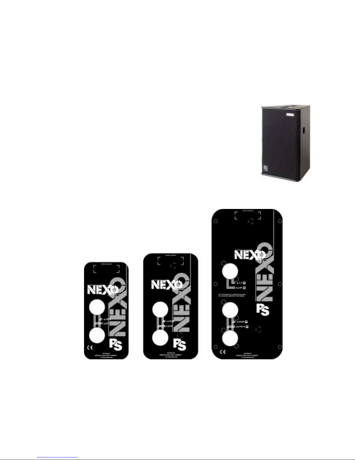
PS15Bass use
The PS15Bass is a pass ive cabinet that us es the s ame signal as the PS15. It
should therefore be connected in parallel with the PS15. You can use the
same controller for both cabinets; both will be equally protected. If you are
using the active mode of the PS15 the PS15Bas s should be plugged into the
LF channel of the PS15 (1+/1-); a shor t adapter will be required (wired from
1+/1- of the PS15 to 2+/2- of the PS15Bass).
Speaker Wiring
The loudspeakers are c onnected with Speakon NL4FC plugs (not supplied). A wiring diagram is printed
on the connection panel located on the back of each cabinet.
The 4 pins of the 2 Speak on sockets identified in / out are connected in parallel within the enclosure.
Either connector can be used when connecting am plif ier s and als o to link to an additional PS cabinet and
optional LSub (if present). This way, a single 4-conductor cable can connect the amplifier rack to 1 or 2 PS
plus 1 LSub.

LOUDSPEAKERS
___________________________________________________________________________________________________
P.
6
On the PS8, LS400, PS10, LS500, PS15 (used in passive mode), PS15 Bass and LS1200, the
connectors are wired as follows:
Speakon Connector Signal
pin 1+
ð
Sub bass + (optional)
pin 1-
ð
Sub bass - (optional)
pin 2+
ð
Main PS system +
pin 2-
ð
Main PS system -
An additional Speakon connector on the PS15 c onnection panel is identified as 2 WAY ACTIVE; it is
reserved for operation in active mode (bi-amp) and wired as follows:
Speakon Connector Signal
Pin 1+
ð
PS15 LF +
Pin 1-
ð
PS15 LF -
Pin 2+
ð
PS15 HF +
Pin 2-
ð
PS15 HF -
Selecting a cable cons ists of calc ulating the corr ect c able section ( size) in relation to the load im pedance
and the required cable length. Too sm all a cable s ec tion would increase its serial resistanc e; which would
induce power-loss and response variations (damping factor).
The following table indicates, for 3 common sizes, a cable length with a maximum serial resistanc e equal
to 4% of the load impedance (damping factor = 25).
Cable Section Maximum Length
Impedance = 8 Ohms Impedance = 4 Ohms
1,5 mm² [AWG # 14] 12 m [40 ft] 6 m [20 ft]
2,5 mm² [AWG #12] 20 m [64 ft] 10 m [32 ft]
4 mm² [AWG #10] 32 m [104 ft] 16 m [52 ft]
Initial Setup Precautions
When f irst powering up a system including brand new cabinets, NEXO recomm ends a gradual power
ramp up on an hour period. This allows the loudspeaker components to stabilize during the very first hours
of usage. This is particularly true for adhesives within the speakers' moving assemblies.

LOUDSPEAKERS
___________________________________________________________________________________________________
P.
7
In all cases it is advisable to connect the loudspeak ers only after all the other system components have
been wired and are operating correctly. This is partic ular ly important f or amplifiers and the TDcontr oller. It
is good practice to turn down all the amplifier s' gains before connecting the cabinets and to turn them on
again individually with a medium level music source fed into the system. The Sense LEDs of the
corresponding TDcontroller channel should light up accordingly. This will help to locate wiring errors,
particularly Left to Right or LF to HF Sense line channel inversions which would disable the TDcontr oller
protection circuits and may invalidate the warranty.
Asymmetrical Horn Configuration
Principle
The Asymmetrical Dispersion Constant Directivity horn is an important feature of the PS Series. This
concept was previously only available for highly specialized applications; in the general purpose PS it is
fully exploited thanks to a practical design that makes user configuration of the horn practical and quick.
The proper configurations of the horn for two common applications are shown below. All 4 positions of the
horn are possible and can be useful for specialized applications such as complex arrays, systems
designed with CAD software and stage monitoring.
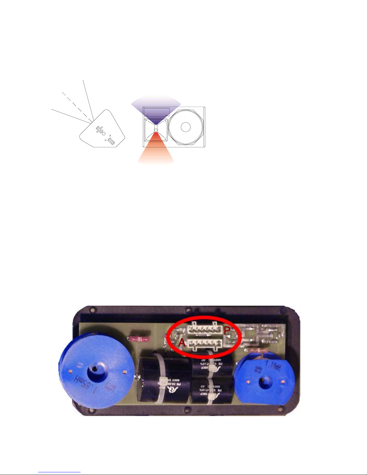
The specific dispersion of the PS8, PS10 & PS15 horn can be seen on figure 1 ("front of house"
configuration):
• As seen on the side view, vertical coverage is narrower above horn axis (+25°) than below (-30°).
• As seen on the front view, horizontal coverage is narrower above horn axis (50° Horizontal for +25°
Vertical) and wider below (100° Horizontal for -30° Vertical). Between these two extremes horizontal
coverage varies according to a specific law; on axis (0° Vertical) coverage is 75° Horizontal.
Access to the horn for c onfiguration and check ing is easily made by removing the front grille (pull gently
the sides of the grille to disconnect the press-st ud fixings). To modif y horn orientation, remove the four
Allen 4 metric or TO RX T X25 screws ( depending of model and age of the cabinet) that hold the horn in
place. A sticker on the wide dispersion side of the horn shows the correct orientation for wedge monitoring
and front of house applications: you simply position the indication on the desired side. The arrow indicates
the wide dispersion.
« Front of house » Configuration
Good coverage of audiences often r equires a
conflicting combination of wide coverage
("short-throw") for the c losest listeners (below
cabinet axis) and narrow coverage ("longthrow") for distant ar eas (on or above axis).
The PS Series horizontal horn coverage
varies from "short-throw" to "long-throw" along
the vertical axis to precisely match these
practical requirements in a single system. For
the majority of applications, the asymm etrical
horn should be used with its "wide" dispersion
side directed towards the floor (as shown by
the arrow) but all four cabinet orientations are
usable.
50˚
100˚
+25˚
-30˚
LOUDSPEAKERS
___________________________________________________________________________________________________
P.
8
« Stage Monitor » Configuration
For stage monitors the required
coverage is always wider when
performers are close to the
wedge (above the horn axis)
than when they move away from
it (below the horn axis). For f loor
monitor use the horn must be
rotated with its "wide" dispersion
side directed towards the top of
the cabinet (as shown by the
arrow) in wedge position as
shown in the above figure. The
specific dispersion pattern, the 2"
driver and the very high power
handling all contribute to the
exceptional performance of the
PS15 as a wedge monitor.
Active / Passive configuration (PS15 Only)
Switching from passive (f actory setting) to active requires modifications to both the PS15 cabinet and
TDcontroller. (For the latter see « Active / Passive switching » page 21).
For the PS15, unscrew the connector plate at the rear of the cabinet (TORX 20 or Allen 2.5) and rotate the
6-pole connector through 180° from socket « P » to socket « A ». Replace the connector plate, taking care
to remove the plas tic blanking plug in the 2 WAY Active Speakon connector. It is strongly recom m ended
to blank off the two PASSIVE Speakon connec tors with blanking plugs to prevent any cabling errors at a
later stage.
See also « Speaker Wiring » section page 5.
100˚
50˚
+30
˚
-2
5
˚
LOUDSPEAKERS
___________________________________________________________________________________________________
P.
9
Sub bass Use (optional)
General Recommendations
The Sub bass section of the TDcontroller is monophonic ( the Left and Right channels are summed at the
input of the Controller). In a Stereo sub bass installation using 2 TDcontrollers, bear in mind that when only
one Controller input is used, this will lower the gain of the Sub Output by -6 dB (as the nominal level is
calculated for a 2 input use). You can either increase the gain setting of the LSub with the front panel level
control or use a Y adapter to feed both inputs of the controller with the same signal. The PS15
TDcontroller MK2 also allows this setting to be made internally by moving jumper 4 (J4) to the “A” position.
(Seeon page 22)
For best results the LSubs should be positioned as close as possible to the PS loudspeakers and aligned
with respect to the audience. This helps to avoid interference near the crossover point.
Although sometimes in c onflict with the above recommendation, LSubs' low frequency performance is
enhanced if multiple subs are grouped together. This also applies to Stereo installations using mono LSub
output where left and right Subs can be grouped together in the center for best effect.
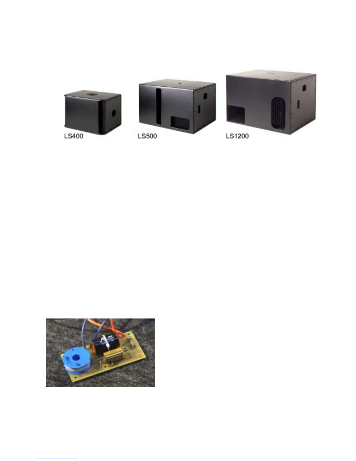
The nominal ef ficiency data for LS400, LS500 and LS1200 and the standard Sub level settings on the
TDcontroller are for LSubs positioned on the floor (half-space). For other system configurations, and
particularly for « flying » subs, the low frequency sound pressure can be -3 to -6 dB lower. This can be
compensated for by a higher setting on the LSub output level control and/or by adding more sub bass
units.
Impedance Compensation Network (ICN) (PS15 Only)
The ICN feature is included in PS15 cabinets since
PS15 serial number 23853. Its main function is to
smooth the impedance curve of the HF driver, thus
improving the passive crossover. The direct result of
this circuit is to flatten the un-equalised respons e curve
(without TDcontroller) and to reduce distortion in the
1kHz-2kHz area. For compatibility with older
TDcontrollers see section « PS15TD MK2: Compatibility
with former PS15TD, LS1000 & PS15 cabinets » page
15. Please also note that this network is available as a
kit to upgrade older cabinets (and TDcontrollers).

LOUDSPEAKERS
___________________________________________________________________________________________________
P.1
0
Accessories
SAFETY recommendation for all accessories
• Always inspect all components for damage before assembly. If you suspect that any of the
components are defective DO NOT USE THE AFFECTED PARTS.
• Carefully read the assembly instructions shipped with each accessory.
• Secondary safety steels must be installed once the system has been flown to operating height.
Secondary steels must be fitted irrespective of the local safety standards applicable to the territory.
• When deploying the flying accessories, always wear protective headwear, footwear and eye
protection.
• Do not allow inexperienced persons to handle flying systems. Installation personnel should be
trained in loudspeaker flying techniques.
• Ensure that motor hoists, hoist control systems and ancillary rigging components are currently
certified as safe and that they pass a visual inspection prior to use.
• Ensure that public and personnel are not allowed to pass beneath the system during the installation
process. The work area should be isolated from public access.
• Never leave the system unattended during the installation process.
• Avoid flying cabinets over areas where the audience has access.
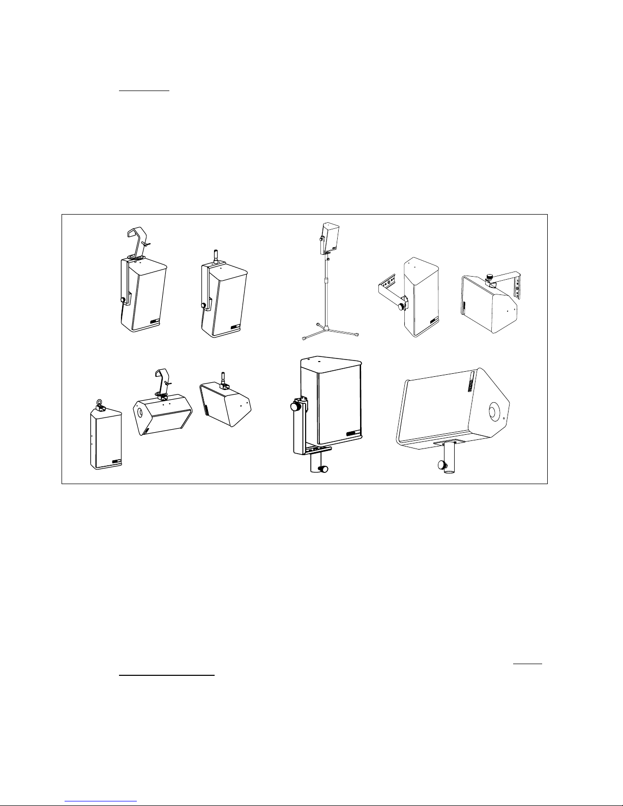
Stand, Mast & U Coupler
PS8, PS10 and PS15 have a built in 35 mm (1 3/8”) diam eter stand adapter. Cabinets can be positioned
directly on a general-purpose speaker stand or on a mast inserted in the stand adapter fitted on top of the
LS400, LS500 & LS1200. The U-Coupler accessory allows positioning and relative rotation of two
cabinets arrayed side by side on top of the m ast or on a speak er stand. T he mas t and U-coupler f or the
PS8 and PS10 are available as options. For safety reasons the use of this U-coupler with the PS15
cabinet is not recommended.
PS10 & PS15 Flying rails & Rings
PS10s and PS15s are equipped with steel anchor plates (standard)
that can be fitted with the following fittings (optional):
• Top: 6 position aircraft-flying rail. (9 for PS15)
• Bottom: two single position round aircraf t flying rails.
(two 3-position aircraft flying rails for PS15)
These rails are supplied as par t of optional flying kits containing all
necessary screws and 4 single stud aircraft flying rings. Heavy-duty
double stud flying rings can be used in all rails except the bottom
PS10 points. Installation requires a m etric N°5 Allen key or TO RX
30 (to remove the original back plate screws) and a metric N°4
Allen key/ TORX 30 to fit the rails.
LOUDSPEAKERS
___________________________________________________________________________________________________
P.11
Vertical orientation of cabinets is a function of ring position in the top rail. It is imperative for security
reasons to use two r ings per rail (lef t figure) link ed to two independently fixed straps. Ring B will also be
used to stabilize the cabinet rotation and reduce the angle given by the master ring A. Nom inal vertical
angles relative to the position of ring A (without the influence of ring B) are as follows:
Position PS10 Angles PS15 Angles
1 -17° -20°
2 -12° -16°
3 -7° -12°
4 -2° -8°
5 +3° -4°
6 +8° 0°
7 NA +4°
8 NA +8°
9 NA +12°
Omnimount® style clamps
The back and the bottom of the PS10 is equipped with internal anchor points (M8 metric) to the
Omnimount® 100 Series spacing standard. This is particularly convenient when cabinets must be
installed permanently in a horizontal or vertical pos ition. To remove the original screws a N°4 metric Allen
key/TORX25 is required. Please note that the O mnimount 100 series is not rated f or the weight of the
PS15. Do not use this accessory with this cabinet without a second proper safety point.
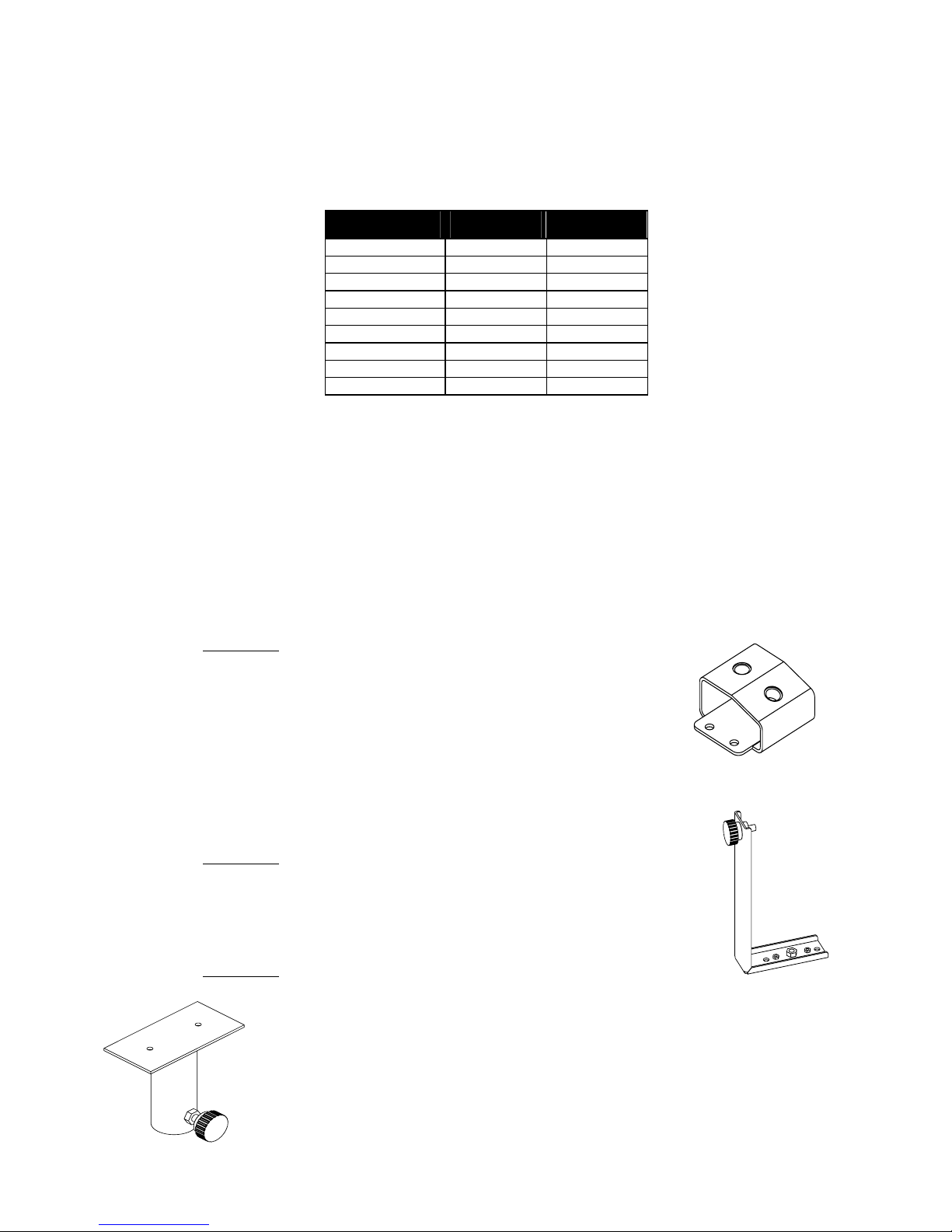
PS8 Accessories
FS0081-001
This accessory is designed to be m ounted directly onto the PS8 cabinet
surface. It provides 2 M10 captive nuts that allow the following accessories
to be fitted: (not supplied in this kit)
• Standard lighting hook/CLAMP
• M10 lifting eye bolt
• DIN Pivot (TV spigot)
FS0081-002
This accessory provides 2 welded M5 nuts and 1 welded M10 nut. (It should
always be used along with the FS0081-001.) This adapter allows the cabinet to
be fixed on the wall, ceiling or on a stand using the FS0081-003
FS0081-003
This adapter is designed for use with the PS8 cabinet. It allows for Horizontal
mounting of the cabinet on a stand or a m ast (∅35mm). It can be used along with
other accessories or it can be fitted directly to the cabinet.
LOUDSPEAKERS
___________________________________________________________________________________________________
P.12
SA0081-001
This safety acce ssory kit conta in s:
o 1 x 30c m steel sling ( plastic covered) + 1 x speed nut & Bolt. Used to provide secondary safety
for the front grille.
Fitting the safety wire is very simple and involves bolting it to the grille assembly and fixing the other end to
one of the HF horn mounting bolts.
Use & Maintenance
Checking the PS10 & PS15 internal fuses
The following paragraph c oncerns only the PS10 and PS15 cabinets, since the PS8 is fitted with a resettable fuse that does not require maintenance.
The function of these fuses is to protect the passive crossover against overheating if a speaker
component is accidentally disconnected or fails open circuit. They can also protect amplifiers from current
overloading in such an event. To preserve sound quality the fuses are not inserted in series with the
loudspeaker components themselves and thus do not protect them directly. If a loudspeaker component
is accidentally disconnected or f ails open circuit and needs repairing, the fus es must be check ed. Their
status can be verified visually and they are easy to replace.
Caution: a broken fus e will degrade sound quality and endanger the loudspeaker components but the
cabinet will still operate. The or der of the passive filter will be reduced; this will lead to an improper phase
matching of the two drivers, and in the case of the HF driver to potentially dangerous excursion. It may not
immediately be noticeable. Incidents that can cause f use br eakage r equire the cabinet to be opened; it is
good practice to always check the fuses in such cases.

LOUDSPEAKERS
___________________________________________________________________________________________________
P.1
3
PS15: These fuses are of the common "autom otive" type (ATO Blade type) with standard values (5A &
10A) on the passive crossover and 5x20 temporized fuse (T500mAL250V) on the ICN circuit.
PS10: These fuses are of the common "autom otive" type (ATO Blade type) with standard values (3A &
10A)
The fuses are located as follows:
• PS10 & PS15 On the PCB of the internal passive crossover located behind the connector panel. Release
the 4 or 6 screws holding the connector panel (Allen m etric 2.5 or T ORX20) and disengage the panel &
crossover assembly (an upward rotation movement is required).
• PS15: On the ICN PCB located near the compression driver. Remove the HF horn; the PCB is located on
the side and is fixed to the side of the cabinet.
Troubleshooting
Simple troubleshooting does not require sophisticated measurement equipment and can be easily
undertaken by users. The technique is to segment the problem by identifying the faulty system
component: signal source, controller, amplifier, loudspeaker or cable? Most installations are multi-channel;
it is often the case that one channel works and others do not. Trying different combinations of system
elements can usually help to isolate and locate the fault.
Some cabinet faults can be quite eas ily located and corrected by the user. A simple sweep with a sine
wave generator can be very helpful but it MUST be made at a fairly low level to prevent damage to the
speakers: A sine wave sweep can help find:
• Vibrations due to loose screws.
• Air-leak noises: check that no screws are missing, particularly where the accessories attach to the
cabinet.
• Vibrations due to a front grille badly positioned on the quick release fixings.
• Some faults require opening the cabinet:
• Fuses (refer to above paragraph)
• Foreign object that has fallen into the cabinet after repair or through the ports.
• Internal connection wires or abs orbing m aterial touching the loudspeak er diaphragm : check by removing
the bass loudspeaker (Allen metric N°4).
• Loudspeaker not connected or phase reversed following a previous inspection, test or repair.
Maintenance & Warranty
Nexo loudspeakers and electronic s are c overed against def ects in workm anship or ma terials for a period
of two (2) years from the original date of pur chase. At the discretion of Nexo, the defective item will be
repaired / replaced with no charge for materials / labor. The item to be repaired must be adequately
packaged and dispatched, prepaid, to an authorized Nexo distributor / s ervice center. Repair by other
distributors / service centers or personnel not authorized by Nexo shall void the warranty. This Nexo
warranty does not cover cosm etics or f inish. It does not apply to any items that have failed due to user
abuse, accidents, modifications or any type of misuse.
 Loading...