

Page 1

PS Series
PS SeriesPS Series
PS Series
PS8 - PS8TD - LS400 - PS8Amp
PS10 - PS10TD - LS500 - PS10Amp
PS15 - PS15Bass - PS15TDMK2 - LS1200
User Manual
Page 2

___________________________________________________________________________________________________
P.2
Norms: TDcontrollers
Norms: TDcontrollersNorms: TDcontrollers
Norms: TDcontrollers
Those equipments have been tested and f ound to comply with the following European and
international Standards for electromagnetic Compatibility and electrical Safety:
• Electrical safety CEI65
• Radiated & conduction emission EN55022: Information technology equipment. Radio disturbance
characteristics. Limits and methods of measurement.
Norms
NormsNorms
Norms: PSAmps
: PSAmps: PSAmps
: PSAmps
This equipment has been tested and found to comply with the following European and
international Standards for electromagnetic Compatibility and electrical Safety:
• Electrical safety CEI65
• EN55013 (emission) Limits and methods of measurement of radio disturbance characteristics of
broadcast receivers and associated equipment.
• EN55020 Electromagnetic immunity of broadcast receivers and associated equipment..
• EN60555-2 Disturbances in supply systems caused by household appliances and similar electrical
equipment. Part 2 : harmonics
• EN 50082-1 Electrom agnetic compatibility. Generic immunity standard. Part 1 : residential, c ommercial
and light industry.
Norms: All PS cabinet & L
Norms: All PS cabinet & LNorms: All PS cabinet & L
Norms: All PS cabinet & LS cabinets
S cabinetsS cabinets
S cabinets
All cabinet described in this manual as passive components are found to comply with
the following European and international Standards for electromagnetic
Compatibility
• EN50081-1: Electromagnetic com patibility. Generic emission standard. Part 1 : residential, commercial
and light industry.
• EN50082-1 : Electrom agnetic compatibility. Generic imm unity standard. Part 1 : residential, comm ercial
and light industry.
Safety Warning concerning TDcontrollers
Safety Warning concerning TDcontrollersSafety Warning concerning TDcontrollers
Safety Warning concerning TDcontrollers
This unit is fitted with 3-pin IEC standard power socket. For safety reasons the earth should not be
disconnected.
To prevent shock or f ire hazard, do not expose the unit to rain or m oistur e. To avoid electr ical shock , do
not remove covers. Dangerous voltages exist inside. Refer servicing to qualified personnel only
PS series User Manual
Revision: 2.01
Date: 05/02/2001
Page 3

___________________________________________________________________________________________________
P.
3
INTRODUCTION................................................................................................................................................................ 4
LOUDSPEAKERS............................................................................................................................................................... 4
GENERAL SETUP INSTRUCTIONS.......................................................................................................................................... 4
ASYMMETRICAL HORN CONFIGURATION............................................................................................................................ 7
ACTIVE / PASSIVE CONFIGURATION (PS15 ONLY) .............................................................................................................. 8
SUB BASS USE (OPTIONAL).................................................................................................................................................... 9
IMPEDANCE COMPENSATION NETWORK (ICN) (PS15 ONLY)............................................................................................ 9
ACCESSORIES ...................................................................................................................................................................... 10
USE & MAINTENANCE ........................................................................................................................................................ 12
TDCONTROLLER USER GUIDE .................................................................................................................................. 14
READ BEFORE USE............................................................................................................................................................... 14
PS15TD MK2: COMPATIBILITY WITH FORMER PS15TD, LS1000 & PS15 CABINETS.................................................. 15
FRONT PANEL...................................................................................................................................................................... 15
REAR PANEL........................................................................................................................................................................ 18
FOLLOWING FUNCTIONS CONCERN PS15TD MK2 ONLY ................................................................................................. 20
SETTING-UP ADVICE........................................................................................................................................................... 22
TDCONTROLLER REFERENCE GUIDE..................................................................................................................... 23
LINEAR SECTION ................................................................................................................................................................. 23
SERVO CONTROL SECTION ................................................................................................................................................. 23
AMPLIFIERS..................................................................................................................................................................... 26
PS8AMP & PS10AMP ......................................................................................................................................................... 26
STAND ALONE AMPLIFIERS................................................................................................................................................. 28
PS8, PS8TD & LS400 : SPECIFICATIONS, CURVES & DIAGRAMS...................................................................... 30
PS10, PS10TD & LS500 : SPECIFICATIONS, CURVES & DIAGRAMS.................................................................. 33
PS15, PS15TD MKII & LS1200 : SPECIFICATIONS, CURVES & DIAGRAMS..................................................... 37
Page 4
INTRODUCTION
___________________________________________________________________________________________________
P.
4
INTRODUCTION
Thank you for selecting NEXO PS Series equipment. This manual will provide you with useful and
important information about your PS speaker system:
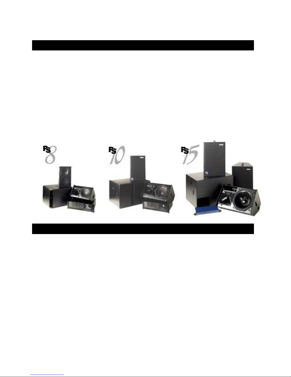
• PS8 & optional LS400 sub bass
• PS10 & optional LS500 sub bass
• PS15 & optional LS1200 sub bass and PS15Bass
The PS15 can be used in either passive or bi-amped mode (two-way active).
Please devote some time reading this manual. A better understanding of some specific features of
the PS series (like the asymmetrical directivity horn configuration) will help you to operate your
system to its full potential.
LOUDSPEAKERS
General Setup Instructions
TDcontroller use
Performance, sound quality and reliability of these speaker systems are entirely dependent on proper
setup and use of the appropriate TDc ontroller: We strongly recomm end that all new users c arefully read
this manual with regard to the specific setup and use of the TDcontroller.
• PS8 TDcontroller for PS8 systems (with or without LS400).
• PS10 TDcontroller for PS10 systems (with or without LS500).
• PS15 TDcontroller MK2 for PS15 systems (with or without LS1200).
• NX241 Digital TDcontroller set on the appropriate set-up (See “NX241 User Manual”)
Page 5
LOUDSPEAKERS
___________________________________________________________________________________________________
P.
5
These controllers are not interchangeable. Eac h one is prec isely matched to the c orres ponding cabinets.
Excepted NX241 that covers the entire NEXO range.
NOTE: Earlier PS15T Ds (up to serial number 1518) were des igned for PS15s without the Impedance
Compensation Network (ICN) (serial number < 23853) and the LS1000 Sub. Using these on newer
cabinets will result in a degradation of sound quality. See page 15 for more information.
PS15Bass use
The PS15Bass is a pass ive cabinet that us es the s ame signal as the PS15. It
should therefore be connected in parallel with the PS15. You can use the
same controller for both cabinets; both will be equally protected. If you are
using the active mode of the PS15 the PS15Bas s should be plugged into the
LF channel of the PS15 (1+/1-); a shor t adapter will be required (wired from
1+/1- of the PS15 to 2+/2- of the PS15Bass).
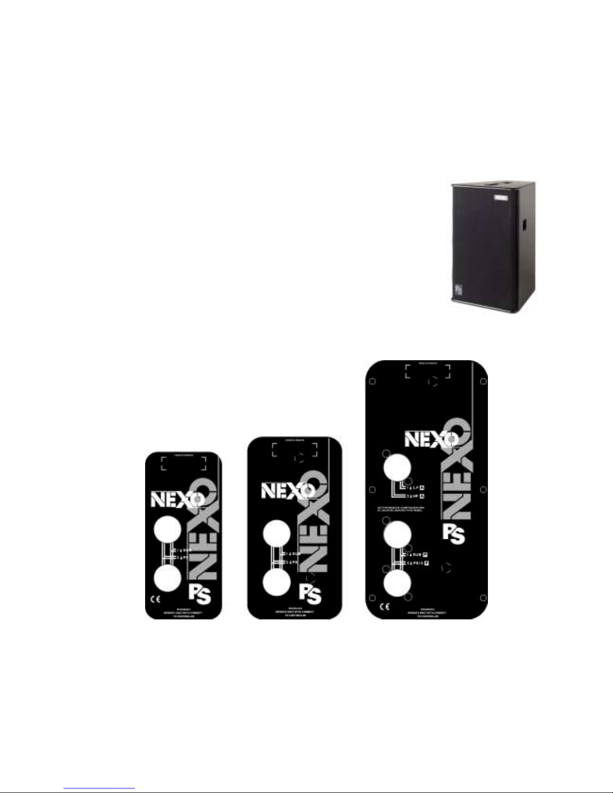
Speaker Wiring
The loudspeakers are c onnected with Speakon NL4FC plugs (not supplied). A wiring diagram is printed
on the connection panel located on the back of each cabinet.
The 4 pins of the 2 Speak on sockets identified in / out are connected in parallel within the enclosure.
Either connector can be used when connecting am plif ier s and als o to link to an additional PS cabinet and
optional LSub (if present). This way, a single 4-conductor cable can connect the amplifier rack to 1 or 2 PS
plus 1 LSub.
Page 6
LOUDSPEAKERS
___________________________________________________________________________________________________
P.
6
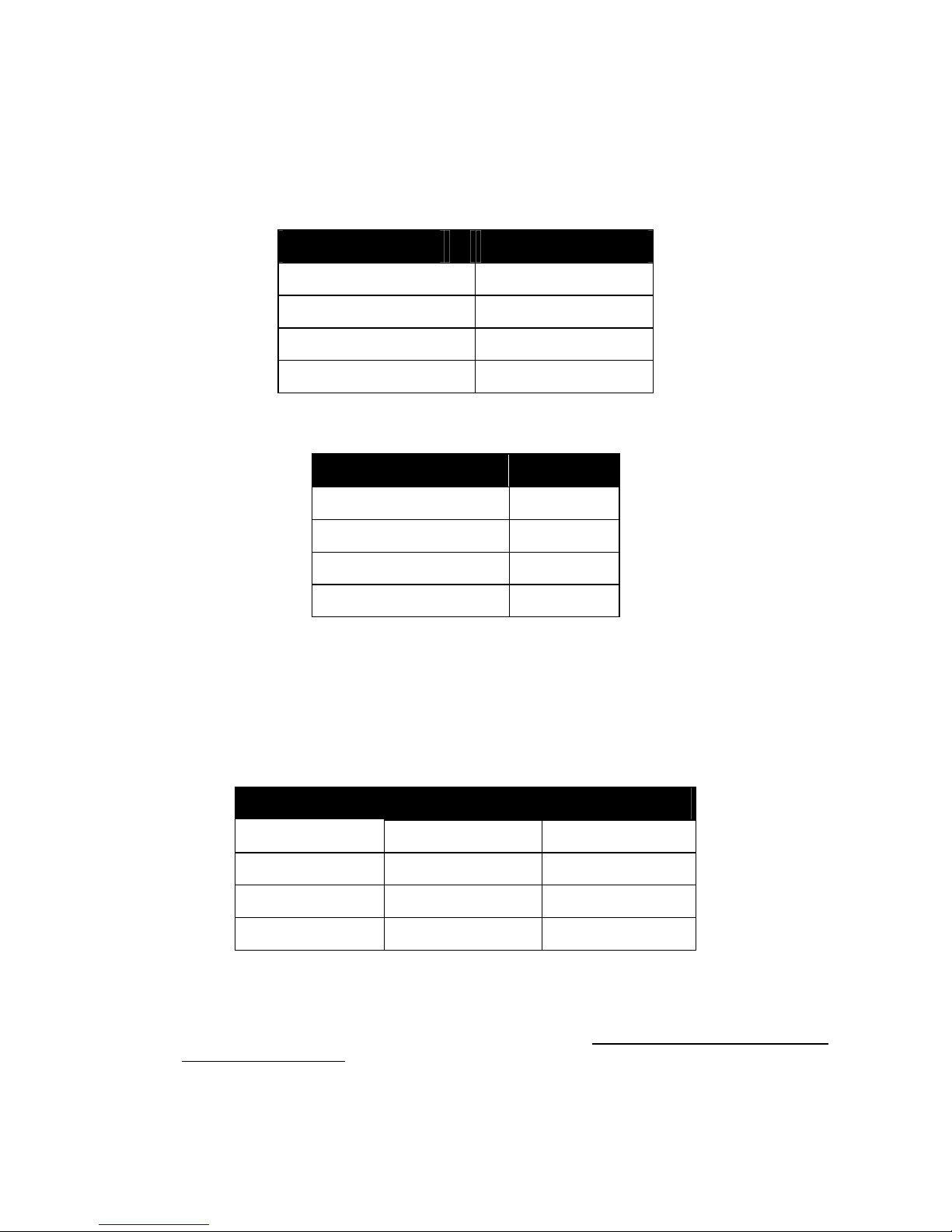
On the PS8, LS400, PS10, LS500, PS15 (used in passive mode), PS15 Bass and LS1200, the
connectors are wired as follows:
Speakon Connector Signal
pin 1+
ð
Sub bass + (optional)
pin 1-
ð
Sub bass - (optional)
pin 2+
ð
Main PS system +
pin 2-
ð
Main PS system -
An additional Speakon connector on the PS15 c onnection panel is identified as 2 WAY ACTIVE; it is
reserved for operation in active mode (bi-amp) and wired as follows:
Speakon Connector Signal
Pin 1+
ð
PS15 LF +
Pin 1-
ð
PS15 LF -
Pin 2+
ð
PS15 HF +
Pin 2-
ð
PS15 HF -
Selecting a cable cons ists of calc ulating the corr ect c able section ( size) in relation to the load im pedance
and the required cable length. Too sm all a cable s ec tion would increase its serial resistanc e; which would
induce power-loss and response variations (damping factor).
The following table indicates, for 3 common sizes, a cable length with a maximum serial resistanc e equal
to 4% of the load impedance (damping factor = 25).
Cable Section Maximum Length
Impedance = 8 Ohms Impedance = 4 Ohms
1,5 mm² [AWG # 14] 12 m [40 ft] 6 m [20 ft]
2,5 mm² [AWG #12] 20 m [64 ft] 10 m [32 ft]
4 mm² [AWG #10] 32 m [104 ft] 16 m [52 ft]
Initial Setup Precautions
When f irst powering up a system including brand new cabinets, NEXO recomm ends a gradual power
ramp up on an hour period. This allows the loudspeaker components to stabilize during the very first hours
of usage. This is particularly true for adhesives within the speakers' moving assemblies.
Page 7

LOUDSPEAKERS
___________________________________________________________________________________________________
P.
7
In all cases it is advisable to connect the loudspeak ers only after all the other system components have
been wired and are operating correctly. This is partic ular ly important f or amplifiers and the TDcontr oller. It
is good practice to turn down all the amplifier s' gains before connecting the cabinets and to turn them on
again individually with a medium level music source fed into the system. The Sense LEDs of the
corresponding TDcontroller channel should light up accordingly. This will help to locate wiring errors,
particularly Left to Right or LF to HF Sense line channel inversions which would disable the TDcontr oller
protection circuits and may invalidate the warranty.
Asymmetrical Horn Configuration
Principle
The Asymmetrical Dispersion Constant Directivity horn is an important feature of the PS Series. This
concept was previously only available for highly specialized applications; in the general purpose PS it is
fully exploited thanks to a practical design that makes user configuration of the horn practical and quick.
The proper configurations of the horn for two common applications are shown below. All 4 positions of the
horn are possible and can be useful for specialized applications such as complex arrays, systems
designed with CAD software and stage monitoring.
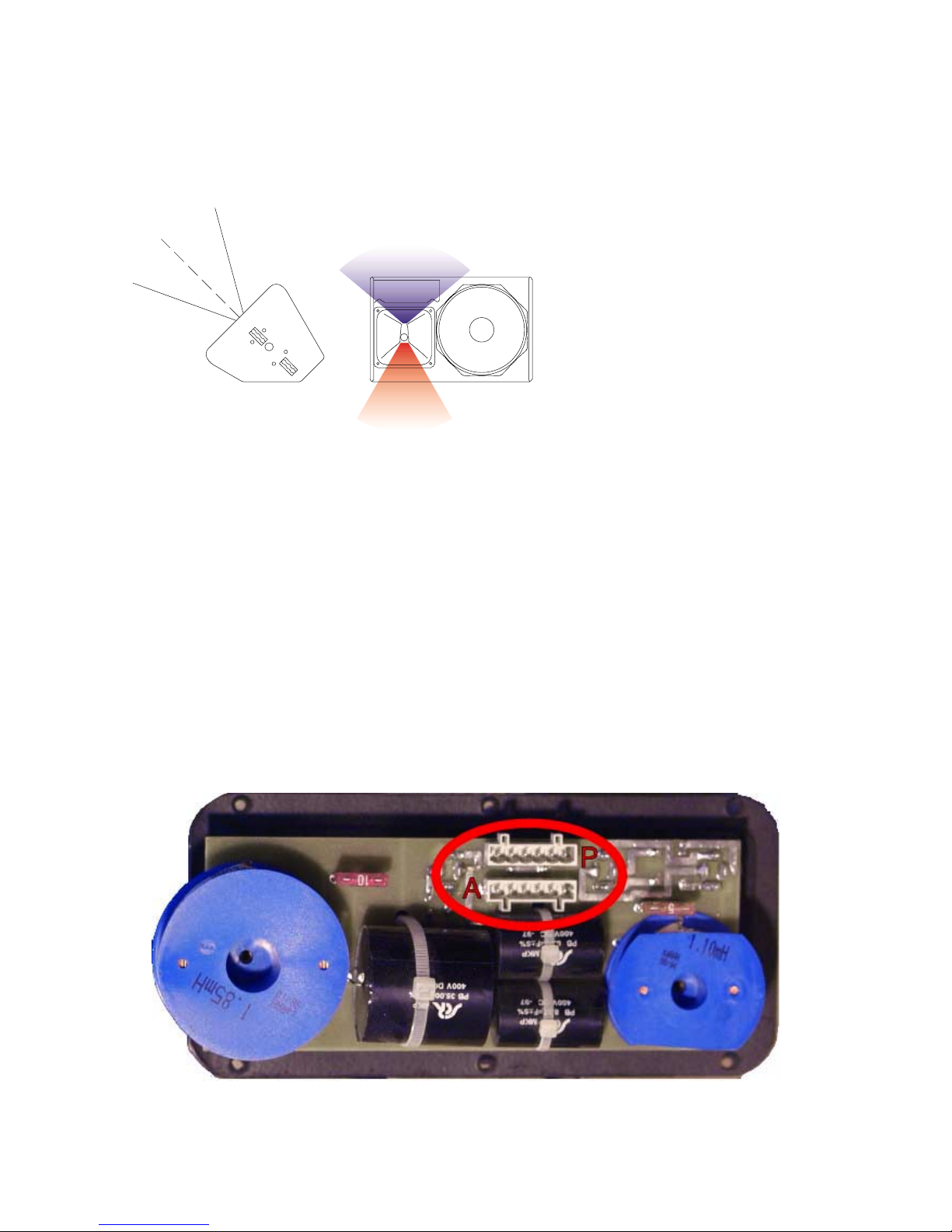
The specific dispersion of the PS8, PS10 & PS15 horn can be seen on figure 1 ("front of house"
configuration):
• As seen on the side view, vertical coverage is narrower above horn axis (+25°) than below (-30°).
• As seen on the front view, horizontal coverage is narrower above horn axis (50° Horizontal for +25°
Vertical) and wider below (100° Horizontal for -30° Vertical). Between these two extremes horizontal
coverage varies according to a specific law; on axis (0° Vertical) coverage is 75° Horizontal.
Access to the horn for c onfiguration and check ing is easily made by removing the front grille (pull gently
the sides of the grille to disconnect the press-st ud fixings). To modif y horn orientation, remove the four
Allen 4 metric or TO RX T X25 screws ( depending of model and age of the cabinet) that hold the horn in
place. A sticker on the wide dispersion side of the horn shows the correct orientation for wedge monitoring
and front of house applications: you simply position the indication on the desired side. The arrow indicates
the wide dispersion.
« Front of house » Configuration
Good coverage of audiences often r equires a
conflicting combination of wide coverage
("short-throw") for the c losest listeners (below
cabinet axis) and narrow coverage ("longthrow") for distant ar eas (on or above axis).
The PS Series horizontal horn coverage
varies from "short-throw" to "long-throw" along
the vertical axis to precisely match these
practical requirements in a single system. For
the majority of applications, the asymm etrical
horn should be used with its "wide" dispersion
side directed towards the floor (as shown by
the arrow) but all four cabinet orientations are
usable.
50˚
100˚
+25˚
-30˚
Page 8
LOUDSPEAKERS
___________________________________________________________________________________________________
P.
8
« Stage Monitor » Configuration
For stage monitors the required
coverage is always wider when
performers are close to the
wedge (above the horn axis)
than when they move away from
it (below the horn axis). For f loor
monitor use the horn must be
rotated with its "wide" dispersion
side directed towards the top of
the cabinet (as shown by the
arrow) in wedge position as
shown in the above figure. The
specific dispersion pattern, the 2"
driver and the very high power
handling all contribute to the
exceptional performance of the
PS15 as a wedge monitor.
Active / Passive configuration (PS15 Only)
Switching from passive (f actory setting) to active requires modifications to both the PS15 cabinet and
TDcontroller. (For the latter see « Active / Passive switching » page 21).
For the PS15, unscrew the connector plate at the rear of the cabinet (TORX 20 or Allen 2.5) and rotate the
6-pole connector through 180° from socket « P » to socket « A ». Replace the connector plate, taking care
to remove the plas tic blanking plug in the 2 WAY Active Speakon connector. It is strongly recom m ended
to blank off the two PASSIVE Speakon connec tors with blanking plugs to prevent any cabling errors at a
later stage.
See also « Speaker Wiring » section page 5.
100˚
50˚
+30
˚
-2
5
˚
Page 9
LOUDSPEAKERS
___________________________________________________________________________________________________
P.
9
Sub bass Use (optional)
General Recommendations
The Sub bass section of the TDcontroller is monophonic ( the Left and Right channels are summed at the
input of the Controller). In a Stereo sub bass installation using 2 TDcontrollers, bear in mind that when only
one Controller input is used, this will lower the gain of the Sub Output by -6 dB (as the nominal level is
calculated for a 2 input use). You can either increase the gain setting of the LSub with the front panel level
control or use a Y adapter to feed both inputs of the controller with the same signal. The PS15
TDcontroller MK2 also allows this setting to be made internally by moving jumper 4 (J4) to the “A” position.
(Seeon page 22)
For best results the LSubs should be positioned as close as possible to the PS loudspeakers and aligned
with respect to the audience. This helps to avoid interference near the crossover point.
Although sometimes in c onflict with the above recommendation, LSubs' low frequency performance is
enhanced if multiple subs are grouped together. This also applies to Stereo installations using mono LSub
output where left and right Subs can be grouped together in the center for best effect.
The nominal ef ficiency data for LS400, LS500 and LS1200 and the standard Sub level settings on the
TDcontroller are for LSubs positioned on the floor (half-space). For other system configurations, and
particularly for « flying » subs, the low frequency sound pressure can be -3 to -6 dB lower. This can be
compensated for by a higher setting on the LSub output level control and/or by adding more sub bass
units.
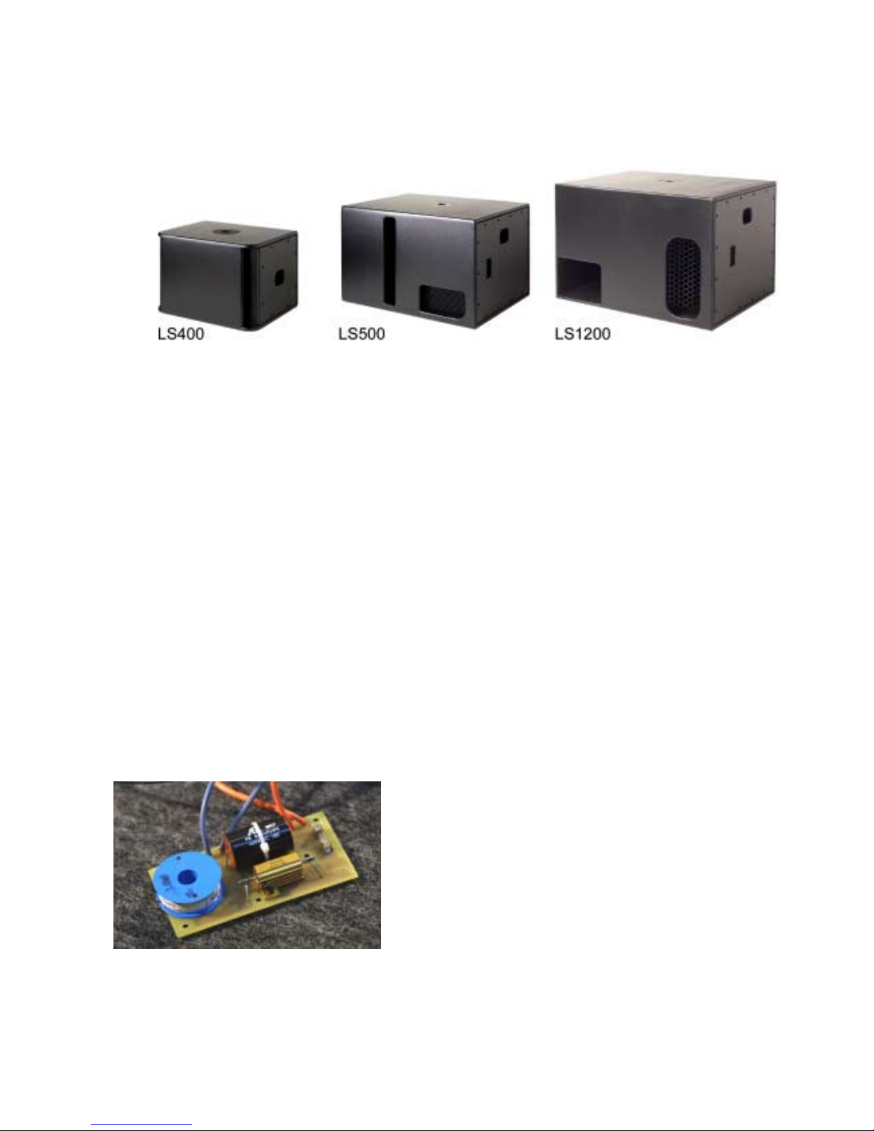
Impedance Compensation Network (ICN) (PS15 Only)
The ICN feature is included in PS15 cabinets since
PS15 serial number 23853. Its main function is to
smooth the impedance curve of the HF driver, thus
improving the passive crossover. The direct result of
this circuit is to flatten the un-equalised respons e curve
(without TDcontroller) and to reduce distortion in the
1kHz-2kHz area. For compatibility with older
TDcontrollers see section « PS15TD MK2: Compatibility
with former PS15TD, LS1000 & PS15 cabinets » page
15. Please also note that this network is available as a
kit to upgrade older cabinets (and TDcontrollers).
Page 10

LOUDSPEAKERS
___________________________________________________________________________________________________
P.1
0
Accessories
SAFETY recommendation for all accessories
• Always inspect all components for damage before assembly. If you suspect that any of the
components are defective DO NOT USE THE AFFECTED PARTS.
• Carefully read the assembly instructions shipped with each accessory.
• Secondary safety steels must be installed once the system has been flown to operating height.
Secondary steels must be fitted irrespective of the local safety standards applicable to the territory.
• When deploying the flying accessories, always wear protective headwear, footwear and eye
protection.
• Do not allow inexperienced persons to handle flying systems. Installation personnel should be
trained in loudspeaker flying techniques.
• Ensure that motor hoists, hoist control systems and ancillary rigging components are currently
certified as safe and that they pass a visual inspection prior to use.
• Ensure that public and personnel are not allowed to pass beneath the system during the installation
process. The work area should be isolated from public access.
• Never leave the system unattended during the installation process.
• Avoid flying cabinets over areas where the audience has access.
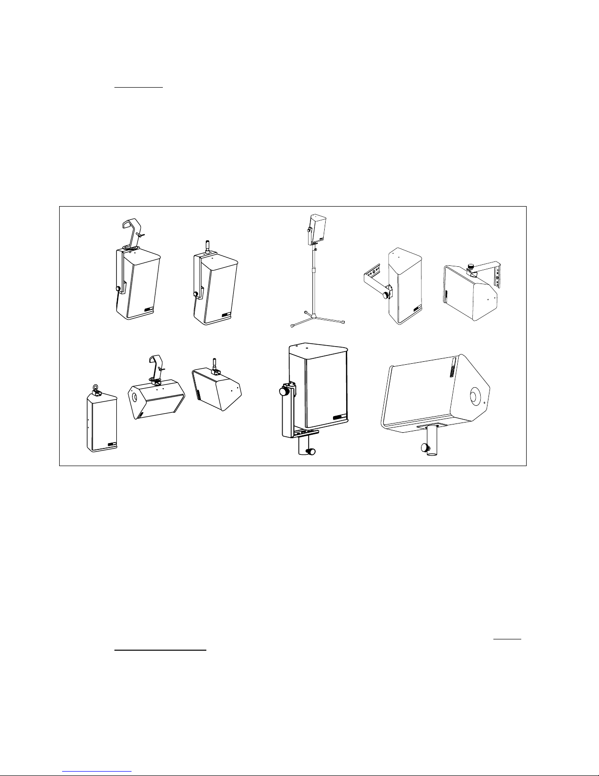
Stand, Mast & U Coupler
PS8, PS10 and PS15 have a built in 35 mm (1 3/8”) diam eter stand adapter. Cabinets can be positioned
directly on a general-purpose speaker stand or on a mast inserted in the stand adapter fitted on top of the
LS400, LS500 & LS1200. The U-Coupler accessory allows positioning and relative rotation of two
cabinets arrayed side by side on top of the m ast or on a speak er stand. T he mas t and U-coupler f or the
PS8 and PS10 are available as options. For safety reasons the use of this U-coupler with the PS15
cabinet is not recommended.
PS10 & PS15 Flying rails & Rings
PS10s and PS15s are equipped with steel anchor plates (standard)
that can be fitted with the following fittings (optional):
• Top: 6 position aircraft-flying rail. (9 for PS15)
• Bottom: two single position round aircraf t flying rails.
(two 3-position aircraft flying rails for PS15)
These rails are supplied as par t of optional flying kits containing all
necessary screws and 4 single stud aircraft flying rings. Heavy-duty
double stud flying rings can be used in all rails except the bottom
PS10 points. Installation requires a m etric N°5 Allen key or TO RX
30 (to remove the original back plate screws) and a metric N°4
Allen key/ TORX 30 to fit the rails.
Page 11
LOUDSPEAKERS
___________________________________________________________________________________________________
P.11
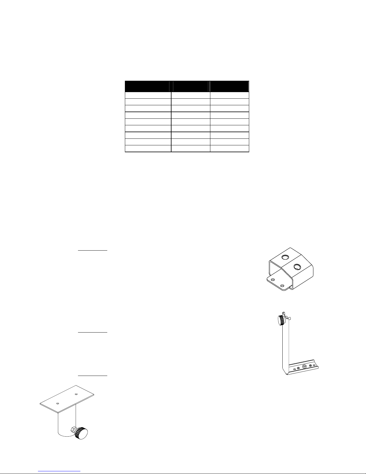
Vertical orientation of cabinets is a function of ring position in the top rail. It is imperative for security
reasons to use two r ings per rail (lef t figure) link ed to two independently fixed straps. Ring B will also be
used to stabilize the cabinet rotation and reduce the angle given by the master ring A. Nom inal vertical
angles relative to the position of ring A (without the influence of ring B) are as follows:
Position PS10 Angles PS15 Angles
1 -17° -20°
2 -12° -16°
3 -7° -12°
4 -2° -8°
5 +3° -4°
6 +8° 0°
7 NA +4°
8 NA +8°
9 NA +12°
Omnimount® style clamps
The back and the bottom of the PS10 is equipped with internal anchor points (M8 metric) to the
Omnimount® 100 Series spacing standard. This is particularly convenient when cabinets must be
installed permanently in a horizontal or vertical pos ition. To remove the original screws a N°4 metric Allen
key/TORX25 is required. Please note that the O mnimount 100 series is not rated f or the weight of the
PS15. Do not use this accessory with this cabinet without a second proper safety point.
PS8 Accessories
FS0081-001
This accessory is designed to be m ounted directly onto the PS8 cabinet
surface. It provides 2 M10 captive nuts that allow the following accessories
to be fitted: (not supplied in this kit)
• Standard lighting hook/CLAMP
• M10 lifting eye bolt
• DIN Pivot (TV spigot)
FS0081-002
This accessory provides 2 welded M5 nuts and 1 welded M10 nut. (It should
always be used along with the FS0081-001.) This adapter allows the cabinet to
be fixed on the wall, ceiling or on a stand using the FS0081-003
FS0081-003
This adapter is designed for use with the PS8 cabinet. It allows for Horizontal
mounting of the cabinet on a stand or a m ast (∅35mm). It can be used along with
other accessories or it can be fitted directly to the cabinet.
Page 12
LOUDSPEAKERS
___________________________________________________________________________________________________
P.12
SA0081-001
This safety acce ssory kit conta in s:
o 1 x 30c m steel sling ( plastic covered) + 1 x speed nut & Bolt. Used to provide secondary safety
for the front grille.
Fitting the safety wire is very simple and involves bolting it to the grille assembly and fixing the other end to
one of the HF horn mounting bolts.
Use & Maintenance
Checking the PS10 & PS15 internal fuses
The following paragraph c oncerns only the PS10 and PS15 cabinets, since the PS8 is fitted with a resettable fuse that does not require maintenance.
The function of these fuses is to protect the passive crossover against overheating if a speaker
component is accidentally disconnected or fails open circuit. They can also protect amplifiers from current
overloading in such an event. To preserve sound quality the fuses are not inserted in series with the
loudspeaker components themselves and thus do not protect them directly. If a loudspeaker component
is accidentally disconnected or f ails open circuit and needs repairing, the fus es must be check ed. Their
status can be verified visually and they are easy to replace.
Caution: a broken fus e will degrade sound quality and endanger the loudspeaker components but the
cabinet will still operate. The or der of the passive filter will be reduced; this will lead to an improper phase
matching of the two drivers, and in the case of the HF driver to potentially dangerous excursion. It may not
immediately be noticeable. Incidents that can cause f use br eakage r equire the cabinet to be opened; it is
good practice to always check the fuses in such cases.
Page 13

LOUDSPEAKERS
___________________________________________________________________________________________________
P.1
3
PS15: These fuses are of the common "autom otive" type (ATO Blade type) with standard values (5A &
10A) on the passive crossover and 5x20 temporized fuse (T500mAL250V) on the ICN circuit.
PS10: These fuses are of the common "autom otive" type (ATO Blade type) with standard values (3A &
10A)
The fuses are located as follows:
• PS10 & PS15 On the PCB of the internal passive crossover located behind the connector panel. Release
the 4 or 6 screws holding the connector panel (Allen m etric 2.5 or T ORX20) and disengage the panel &
crossover assembly (an upward rotation movement is required).
• PS15: On the ICN PCB located near the compression driver. Remove the HF horn; the PCB is located on
the side and is fixed to the side of the cabinet.
Troubleshooting
Simple troubleshooting does not require sophisticated measurement equipment and can be easily
undertaken by users. The technique is to segment the problem by identifying the faulty system
component: signal source, controller, amplifier, loudspeaker or cable? Most installations are multi-channel;
it is often the case that one channel works and others do not. Trying different combinations of system
elements can usually help to isolate and locate the fault.
Some cabinet faults can be quite eas ily located and corrected by the user. A simple sweep with a sine
wave generator can be very helpful but it MUST be made at a fairly low level to prevent damage to the
speakers: A sine wave sweep can help find:
• Vibrations due to loose screws.
• Air-leak noises: check that no screws are missing, particularly where the accessories attach to the
cabinet.
• Vibrations due to a front grille badly positioned on the quick release fixings.
• Some faults require opening the cabinet:
• Fuses (refer to above paragraph)
• Foreign object that has fallen into the cabinet after repair or through the ports.
• Internal connection wires or abs orbing m aterial touching the loudspeak er diaphragm : check by removing
the bass loudspeaker (Allen metric N°4).
• Loudspeaker not connected or phase reversed following a previous inspection, test or repair.
Maintenance & Warranty
Nexo loudspeakers and electronic s are c overed against def ects in workm anship or ma terials for a period
of two (2) years from the original date of pur chase. At the discretion of Nexo, the defective item will be
repaired / replaced with no charge for materials / labor. The item to be repaired must be adequately
packaged and dispatched, prepaid, to an authorized Nexo distributor / s ervice center. Repair by other
distributors / service centers or personnel not authorized by Nexo shall void the warranty. This Nexo
warranty does not cover cosm etics or f inish. It does not apply to any items that have failed due to user
abuse, accidents, modifications or any type of misuse.
Page 14
TDCONTROLLER USER GUIDE
___________________________________________________________________________________________________
P.1
4
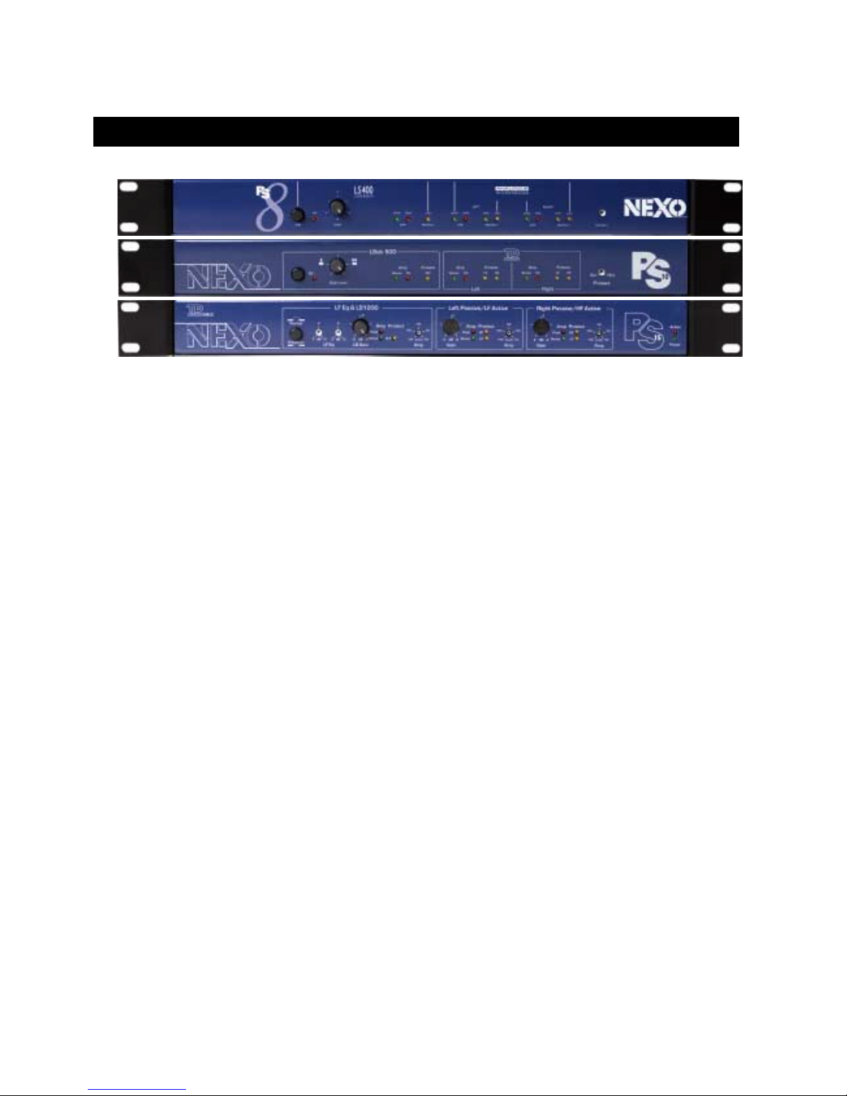
TDcontroller USER GUIDE
This section describes the Analogue TDcontroller PS8TD, PS10, and PS15MK2. For information
concerning the NX241 Digital TDcontroller, please refer to the NX241 Operating Manual.
Read before use
The PS TDcontroller is designed to be used with PS and LSub speaker cabinets. Its main functions are:
• To optimize the response of the system
• When operating with a Sub-bass system (optional), splitting the stereo (2 channel) signal into 2 frequency
bands (PS main system and LSub Sub-bass system)
• When operating in active configuration (PS15 only), splitting the mono (single channel) signal into 3
frequency bands (SUB, LF & HF)
• Active protection of the cabinets by dynamic audio signal processing (T emperature and Displacement
servo control)
• Reduction of amplifier overload (Peak limiter function)
PS TDcontrollers also feature:
• Stereo operation (2 independent channels) for the main system
• Global switchable output level according to amplifier gain
• Individual gain control for each channel (PS15 only)
• Adjustable level on the Sub-bass channel
• Balanced input and output stages (High CMRR input stage and High current drive output on PS15TD)
• User array LF EQ (PS15TD only)
• Enhanced protection facility for additional safety margin when the cabinet is subjected to extended periods
of overload.
• Fallback servo control m ode prevents protection loss when sense lines are accidentally disconnected
Page 15

TDCONTROLLER USER GUIDE
___________________________________________________________________________________________________
P.1
5
(NB: on PS10TD, this feature is provided only after serial number 361 and not at all on PS15TD MKII).
• Compensation of power compression effects on the system response curve..
The PS TDcontroller is designed to be inserted between the Audio source (console, preamplifier, etc.) and
the power amplifier.
PS15TD MK2: Compatibility with former PS15TD, LS1000 & PS15 cabinets
PS15TD MK2 with PS15 cabinet without Impedance Compensation Network (ICN)
Internal jumpers J1 & J6 in the TD MK2 provide total com patibility for a PS15 cabinet with or without ICN
(shipped with PS15 since sn 23853).
The PS15TDcontroller MK2 is f actory set to be used with ICN. Using old PS15 cabinets with the T DMK2
without changing internal jumpers (see page 21) will result in a boost of 3dB at 1400Hz and a decrease in
sound quality: if the TDcontroller cannot be changed, a tem porary solution would be to apply an inverse
EQ before the TDcontroller.
PS15TD MK2 with LS1000 cabinet
We s trongly advise that you do NOT use LS1000 before serial num ber 560 with the PS15TD MK2. The
driver in early model LS1000s cannot withstand the amount of energy provided by the new electrical
cross-over.
LS1000 above serial number 560 are equipped with the new 18’’ NEXO driver and with these units it is
possible to use the T Dcontroller MK2. Keep in mind that the cross-over is not tuned for the LS1000
architecture and sound quality will be not be as good as with the LS1200.
PS15 cabinet with ICN used with earlier PS15TD
As the non-equalized response of the PS15 cabinet is flattest with the ICN, the use of an old PS15TD
(with higher equalization) will result in a cut of 3dB at 1400Hz.
A modification can be made on early PS15TDs (contact your NEXO dealer). Disconnecting the ICN (near
the HF horn) is also possible (in that case your cabinet is identical to earlier models before sn 23853).
LS1200 used with former PS15TD
In this case, the LS1200 will be under driven. The cross over will not match the cabinet architecture. No
sound improvem ent (vs. LS1000) should be expected. A m odification can be m ade to your old PS15TD
(contact your NEXO dealer), but it will be no longer compatible with the LS1000.
Front Panel
Most front panel f unctions and indicators are located ins ide 2 distinct windows: left-hand areas relate to
functions and indicators dedicated to the optional Sub-bass section, while right-hand window contains
indicators concerning servo control operation for the PS cabinets.
For more technical details about servo control operation and internal electronic processing, please refer to
section “TDcontroller REFERENCE GUIDE.” Page 23.
Page 16
TDCONTROLLER USER GUIDE
___________________________________________________________________________________________________
P.1
6
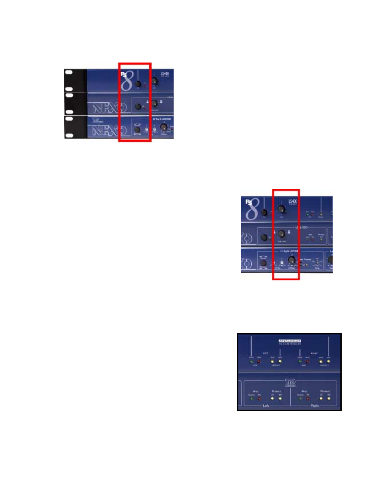
Turning the LSub channel on (On) (Overlap / Crossover for PS15)
For use with the PS8 & PS10 cabinets , pushing the LSub
button turns the Sub-bass channel On (Sub L + R output),
which feeds the amplifier(s) driving the LSub cabinet(s).
Signals below 120 Hz are then reassigned after Left + Right
summation to this output, while the main Left & Right
channels are high-pass filtered at the same frequency.
When not using Subs, this switch must be released for
proper operation of the PS cabinet. A red LED indicates that
the function is in operation (button pushed in).
In the case of the PS15 MKII TD controller, this button
modifies the high pass filtering. It does not affect the sub output, which will always be a filtered sub signal.
(This is therefore not a Sub on/of f button although the older PS15TD operates as the PS8/PS10 units
described above). In the « Overlap » position, the PS15 is exploited to its maximum capability. This
position should be used if the system is being used without a LS1200. It can also be used with the
LS1200; In this case, there will be a boost in the crossover area. T he « Cross over » position is generally
recommended when using the LS1200.
Adjusting the LSub level (Sub Level)
The potentiometer adjusts the level of the Sub-bass channel, a range
of 12 dB allows a variety of configurations and application conditions
to be accomm odated. Icons show the 2 standard pos itions; 1 LSub
for 1 PS cabinet, and 1 LSub for 2 coupled PS cabinets. Center
position of the knob is calibrated for 1 LSub used with 2 distant PS.
Amplifier control (Sense & Pk)
The green Sense LED indicates signal presence at the sense input
of the concerned channel, allowing vis ual c onfir m ation of the return c onnection of the Sense cables fr om
the amplifier output.
The red Peak LED indicates that the Peak limiter is acting, reducing excessive peak voltage or levels
capable of overloading the channel amplifier.
Protection indicator
• The yellow VLF LED indicates that temperature or displacement
protection for the LSub are engaged on the Sub-bass channel. On
the PS8TDcontroller only the displacement protection is monitored.
• On each side of the PS main system window, yellow LF and HF
LEDs indicate when protection has been ac tivated (temperature or
displacement control) f or either the LF or the HF driver respectively
on the Left or Right channel. On the PS8TDcontroller the LED
indicate the displacem ent and temperature protection of the bass
driver only.
Page 17
TDCONTROLLER USER GUIDE
___________________________________________________________________________________________________
P.1
7
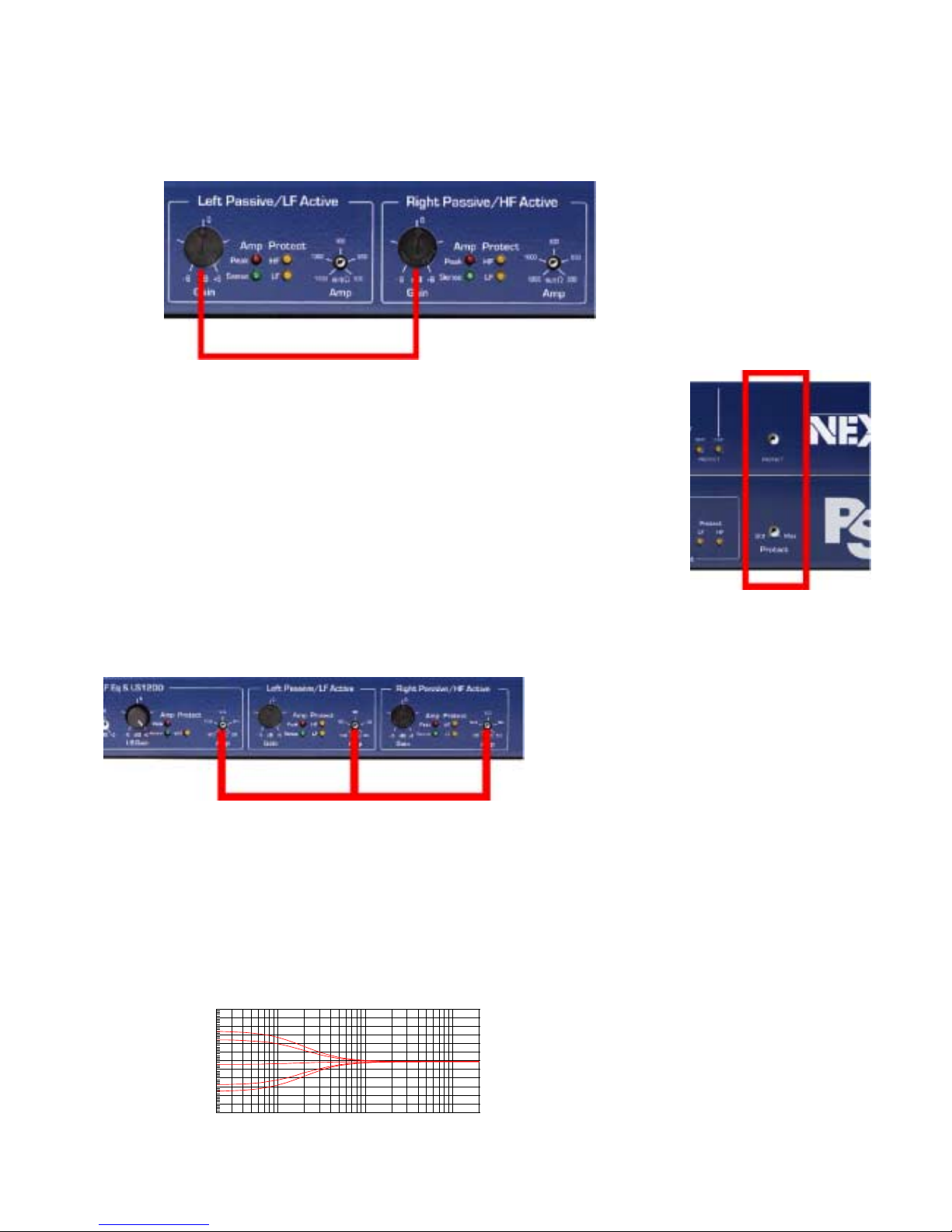
PS15 Gain control (PS15TD only)
Two 12 dB range trimmers are
provided to set the gain of L&R (HF &
LF in active mode) channels. This
adjustment can be useful in active
mode where it is sometimes necessary
to correct the gain difference of
amplifiers which have different power
and constant sensitivity. The factory
position is in the middle (detent), which
correspond to 0 dB gain.
Enhanced protection trimmer (Protect)
The embedded trim mer located on the right side of the front panel (outside
the window) is used to lower the threshold of the protection system. W hen
turned fully to the left (marked Std), speaker protection is set for normal
operation. When turned fully clockwise (marked Max), protection is increased;
e.g. this setting should be used when the system is operating under badly
controlled conditions (eg. W hen amplifier gain are not k nown or sense lines
are not connected…). Middle positions of the trim mer can also be us ed and
are recommended in cases where extended periods of overload (e.g. in some
discotheque applications) are expected.
Peak Limiter adjustments (PS15TD only)
The PS15TD MK2 features three independent peak limiter trims, which allows the peak limiter to be set to
limit the m aximum power of the am p (without affecting the protection threshold as im plemented in the
earlier version of the PS15TD). The
peak limiter has no real cabinet
protection functions; it mus t be tuned
to avoid overdriving the amp that in
turn can generate obvious clipping
noise and very low frequencies
(caused by the modulation of the
power supply rails).
To set the peak limiter to the correct value, either turn the trimmer clockwise until the red LED lights at the
same time as the amp’s clipping LED, or use the graduation (power value given for 8 Ω load).
Active & Power LED (PS15T D MKII only)
At the left side of the TDcontroller a green LED indicates the unit is powered, and a red one indic ates the
active mode is selected.
LF Eq. (PS15TD MKII only)
This control increases (or decreases) of the Low
Frequencies (on both PS and LSub). It acts sim ilar to a
shelving filter with a range of +/- 3 dB
-6
+6
-5
-4
-3
-2
-1
+0
+1
+2
+3
+4
+5
d
B
V
20 20k50 100 200 500 1k 2k 5k 10k
Hz
Page 18
TDCONTROLLER USER GUIDE
___________________________________________________________________________________________________
P.1
8
Rear Panel
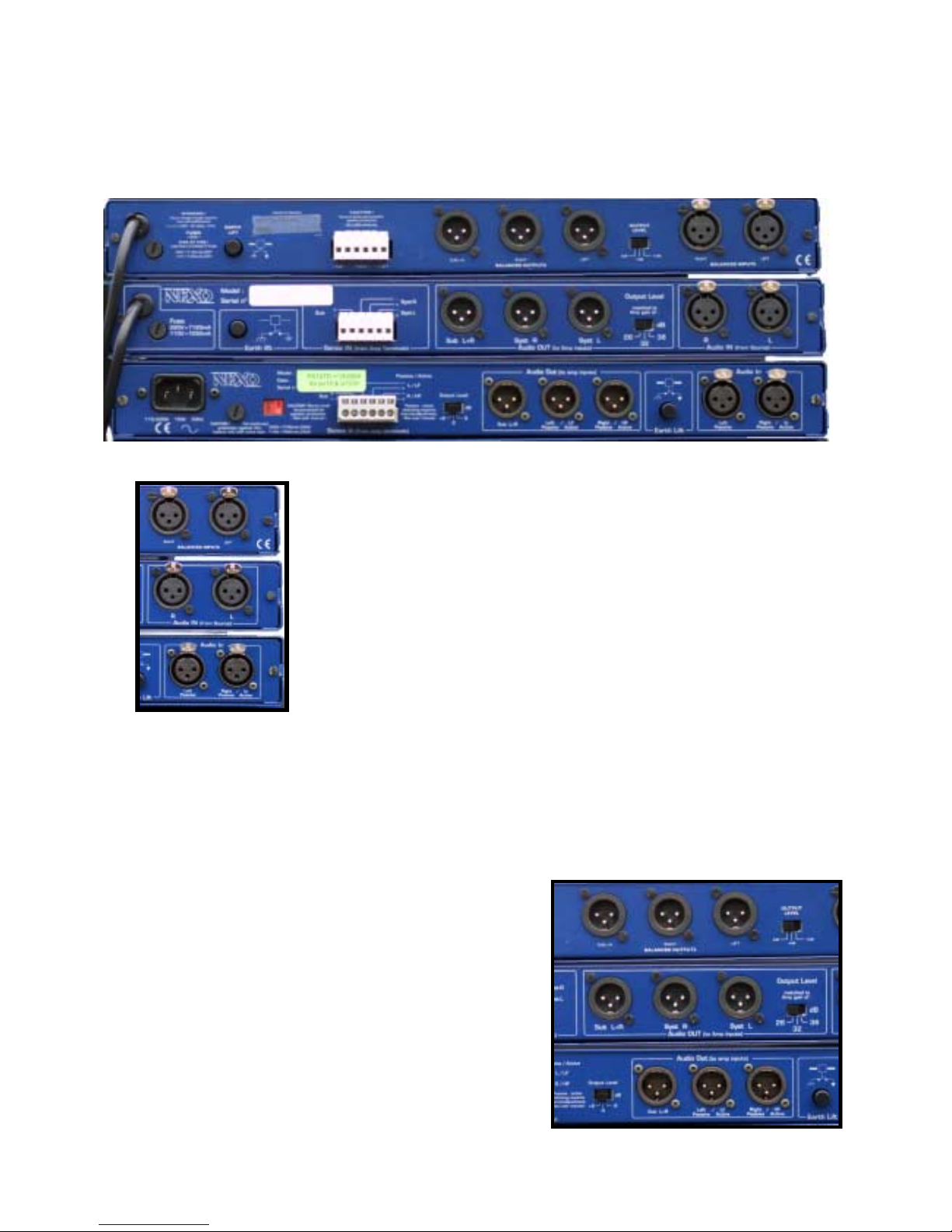
Audio Inputs
The audio inputs are two 3-pin female XLR connectors located in the area
labeled Audio IN, L and R being the left and right c hannels respectively.
When using the ac tive mode on the PS15TD only the Left channel XLR
connector is used. Signal is applied between pins 2 and 3, pin 1 is
connected to ground. When the Controller is linked to a signal source with
balanced outputs, the XLR connections are simply wired pin to pin (1 to 1,
etc.). As a res ult of the balanc ed natur e of the outputs (and pr oviding that
balancing is respected by way of the connection to the amplifier), there is
no hot or cold pin - the PS TDcontroller being neutral regarding the
polarity of the signal.
In cases where an unbalanced source is connected to the inputs, the
connections should be made as follows to preserve signal polarity:
• If the amplifiers connected to the outputs of the PS TDcontroller are wired pin 3 hot, connect the hot pin of
the source to pin 3 of the Audio input XLR of the PS TDcontroller.
• If the amplifiers are wired pin 2 hot, connect the hot pin of the source to pin 2 of the Audio input XLR.
In both cases the unused signal pin (2 or 3 respectively) should be linked to pin 1 (grounded).
Audio Outputs
The audio outputs are the three 3-pin male X LRs located
in the area labeled Audio OUT. The channel
corresponding to each output connector is identified by the
labels Syst L (left channel), Syst R (right channel), and Sub
L+R (mono Sub-bass).
Signal is applied between pins 2 and 3, pin 1 is connected
Page 19
TDCONTROLLER USER GUIDE
___________________________________________________________________________________________________
P.1
9
to ground.
When used with an amplifier with balanced inputs, the wiring of the output XLR is simply pin to pin (1 to 1,
etc.), the polarity of the s ignal being pr eser ved if the s our ce c onnec ted to the input is also balanc ed ( see
previous section).
Where an amplifier with unbalanced inputs is used, the connections should be made as follows :
• Where the s ourc e c onnected to the PS TDcontroller input is pin 3 hot, connect the hot pin of the amplifier
to pin 3 of the PS TDcontroller XLR output connector and the amplifier ground to pin 2.
• Where the sourc e is wired pin 2 hot, connect the hot pin of the am plifier input to pin 2 of the X LR output
connector, and the amplifier ground to pin 3.
• Leave pin 1 of the output XLR unconnected.
This wiring method avoids any loss of output level, provided that the ground of the PS T Dcontr oller stays
floating relative to that of the amplifier -thus care should be taken with regard to the Earth Lift switch when
it is depressed: the respective signal grounds could possibly be linked together via the mains earth).
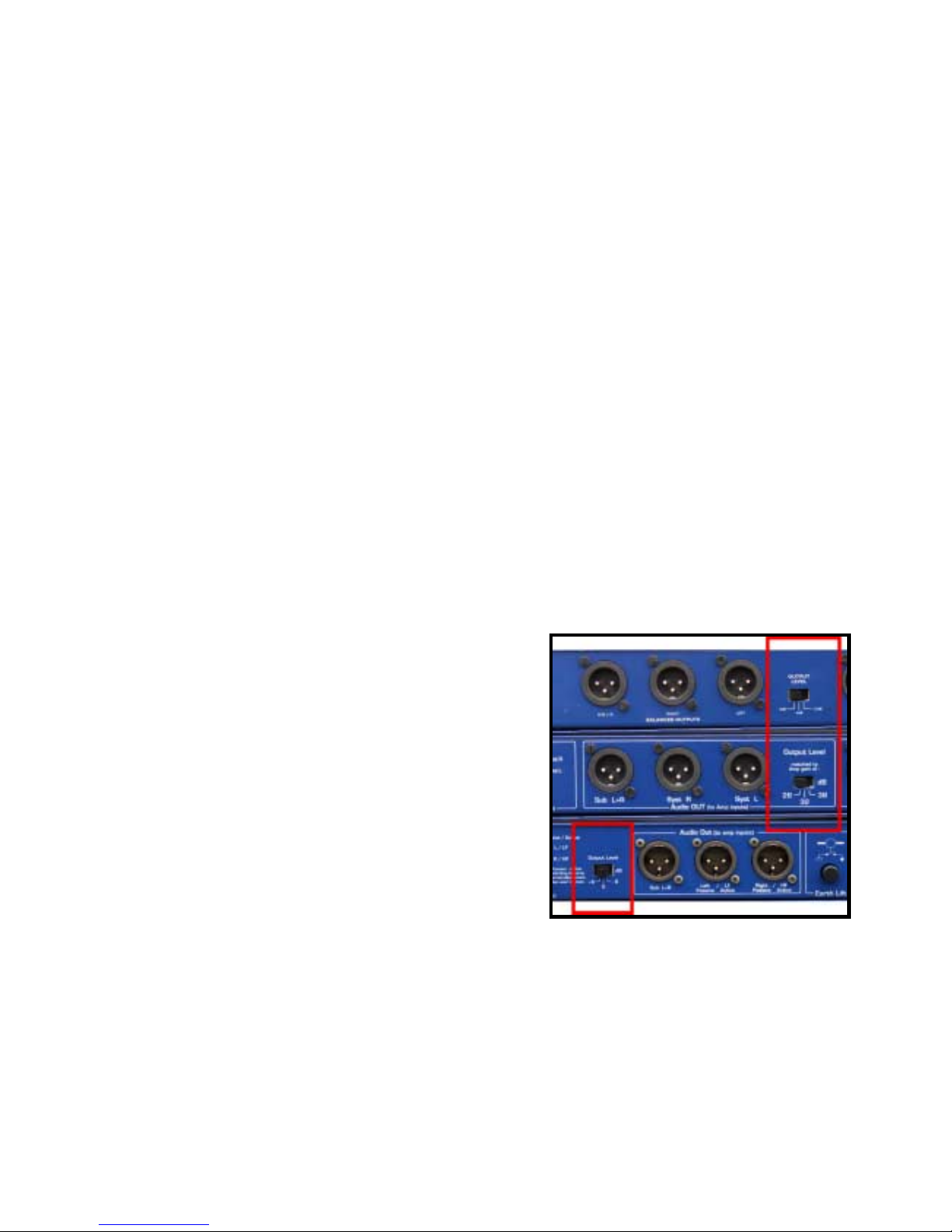
Output Level Switch
The 3 position output level switch has two main purposes :
1. Once the sense lines are connected, this switch is only used to match the processor gain to the amplifier
gain for optimum signal to noise ratio. Having selected the appropr iate output level, the signal to noise
ratio will be preserved whatever the gain of the amplif ier (for a broader explanation of this please refer to
page 28).
2. If the sense lines are disconnected, the TDc ontroller is
operating in fall back mode (Does not apply to PS15
MKII). In this case, selecting the proper switch
setting is absolutely essential to ensure the correct
operation of the protection circuits. For the PS8TD
(labels –12dB –6dB OdB) an attenuation of 12dB
should be made for 38dB am plifier gain and 6dB for
32dB amplifier gain. (the 0dB position co rresponds to
26dB amplifier gain)
The three gain values available are 26, 32 or 38 dB
and correspond to the positions left, middle and right of
the switch respectively. If the effective gain of the
amplifiers doesn’t correspond to any of the three
positions the closest should be selected. In case of
doubt, the lesser value should be chosen.
For the PS15TD The three gain values available ar e +6dB, 0 & -6dB. For minim um nois e floor the -6dB
setting should be chosen, for maximum headroom the +6dB position should be used.
Page 20
TDCONTROLLER USER GUIDE
___________________________________________________________________________________________________
P.2
0
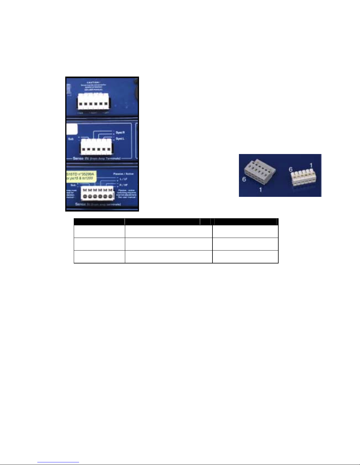
Sense inputs
The sense inputs of the three channels (left, right and subbass) are
arranged on a six pole barrier s trip set into the rear panel within the area
labeled Sense IN. The Sense inputs are intended for connection to the
output signals of the amplifier s driving one cabinet of each the channels
being used : PS for the left and right channel, LSub for the subbass
channel.
Input sense connection is strongly recomm ended for proper operation of
the servo-control system. On PS15TDcontroller MKII (and PS10
TDcontrollers with serial num bers before #360) which do not have fallback mode, the cabinets will NOT BE PROTECTED if the sense lines are
unconnected.
Connection is made via the female part
- removable - of the connector
(supplied with the Controller) as
outlined below :
Channel Amplifier Output Terminal Barrier strip connector
PS Left (Syst L) + (red)
ð
pin 1 (figure)
- (black)
ð
pin 2
PS Right (Syst R) + (red)
ð
pin 3
- (black)
ð
pin 4
LSub (Sub) + (red)
ð
pin 5
- (black)
ð
pin 6
NB : The PS TDc ontroller is ins ensitive to the polarity of the wiring of the inputs, contrary to some other
NEXO Controllers. It is highly recom mended that the user read the all of the inform ation provided below
regarding the wiring of Sense lines (0.0.0 : Recommendations for wiring the Sense lines).
Earth Lift
The push button labeled « Earth Lift » allows connection (depressed position), or disconnection (out
position) between the signal ground and the mains earth, which is its elf linked to the chass is. Using this
button may help to eliminate hum due to ground loops created in the system.
Following functions concern PS15TD MK2 only
Voltage selector (PS15)
According to CEI65 and UL1419 norms, an external voltage selector is pr ovided at the back of the unit. It
will allow the controller to work with either normalized voltage (230V or 115V).
WARNING : Changing the voltage selector requires changing the fuse.
Page 21
TDCONTROLLER USER GUIDE
___________________________________________________________________________________________________
P.21
Fuse holder (PS15)
When necessary, the fuse should be replaced by a fuse of the same rating
• for 230V : T100mAL250V
• for 115V : T200mAL250V
Mains Socket (PS15)
WARNING : This appliance must be earthed.
The socket is compatible with mains supply flexible cords which comply with IEC Publication 227.
Functions requiring the opening of the TDcontroller
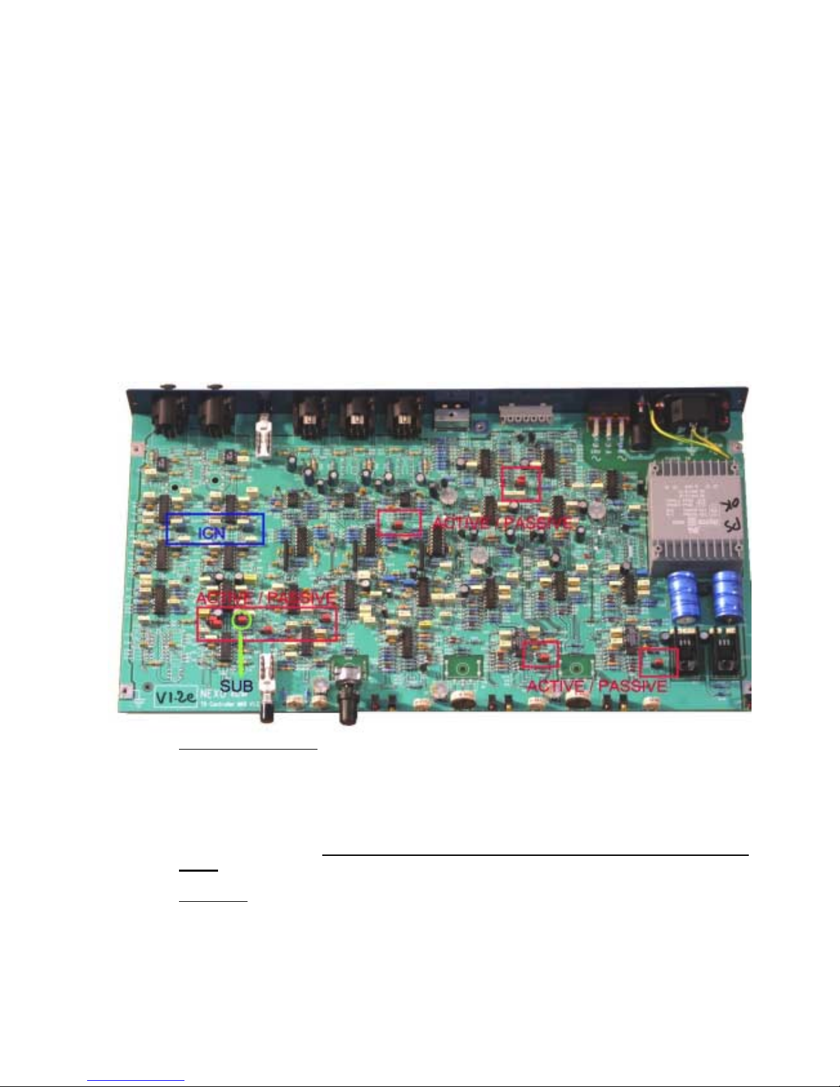
Active / Pa ssiv e sw itch ing
The switching between active mode and passive mode is made by 9 RED jumpers, designated J3-J4-J5J8-J9-J10-J11-J12-J13.
All 9 jumpers m ust always be in the same position; right side for passive mode (label « P », left side for
active mode (label « A »). Incorrect jumper selection may damage your speakers and impair sound
quality !
ICN jumpers
If your PS15 cabinet is equipped with the Impedance Compensation Network (ICN) -since sn 23853, the
blue Jumpers J1 & J6 must be in the « P » position (right side).
Page 22

TDCONTROLLER USER GUIDE
___________________________________________________________________________________________________
P.22
If your are using this TDcontroller with a PS15 cabinet without an ICN, the ICN jumpers must be set to the
« A » position (left side). If not, a boost of 3dB at 1400Hz will result, affecting the sound quality of your
system.
Sub jumper
In certain applications you may wish to disable the mono summation (but keep the 6dB gain boost) on the
sub channel. By moving the J4 jumper to the left position ( « A »), the sub channel will only use the Right
input (with 6dB gain to keep the same sub level when the mono summation is enabled)
Setting-Up Advice
Recommendations for wiring the Sense lines
The impedance of the sense inputs of the PS TDcontroller are quite high, so currents are low and
therefore ordinary light duty cable can be used. If the TDcontroller is housed in the amp racks an
unshielded cable can be used.
If the Controller is located remotely - at the m ixing position - a shielded cable is recom mended, without
using the shield as a conductor.
When one of the channels is not being used and the corresponding sense line is disconnected, cross talk
onto the inactive sense line may in some cases produce signals capable of causing the inadvertent
illumination of the Sense LED on that channel ; although this has no effect on the internal operation of the
Controller, it can be cured by short-circuiting the terminals of the inactive sense line.
In all cases, it is strongly advised to protect the amplifiers from short-circuits in the sense lines. It is
recommended that a 1 kOhm resistor with a power rating of at least thr ee watts be inser ted in s eries with
one of the sense line cables as close as possible to the output terminals of the amps.
Connecting the audio outputs
The output stages can drive several amplifiers in parallel ; however it is not advisable to work with loads of
less than 1 kOhm. It is best to check the impedance characteristics of the amplifier inputs - supplied by the
manufacturer - to check how many amplifier channels can be paralleled. Where precise information is not
available (and taking 10 kO hm as the minim um value possible), ten channels in parallel per output is a
sens i b l e ma x i mu m.
Page 23

TDCONTROLLER REFERENCE GUIDE
___________________________________________________________________________________________________
P.2
3
TDcontroller REFERENCE GUIDE
Linear section
The characteristics of the linear section are independent of s ignal level, as opposed to the servo control
functions described in next paragraph.
Subsonic and VHF filtering
Low and high-pass filters ar e used to rem ove signals out of the usable f requenc y range, eliminating suband ultra-sonic components that c ould pos s ibly degrade the performance of the Controller and amplifiers.
These filters are optimized to realize the overall target system response.
Equalizing acoustical response
This equalization section provides the required correction to obtain a flat system response, as the cabinets
are acoustically designed for maximum efficiency in the whole frequency range. Active rather than passive
attenuation allows amplifier voltages to be lowering for a given output SPL and theref ore increases the
maximum SPL achievable with the same amplifier.
Active equalization also extends system bandpass, especially at low frequencies where acoustical
performance is limited by cabinet size.
PS / LSub Cross-Over
From input signals sum med together, the r esulting m ono signal is low-pass f iltered to feed the Sub-bas s
channel. When the c hannel is turned on (LSub On), main channels (Left & Right) high-pass filters are
reconfigured to filter out signal components below the cross-over frequency. Slopes and other filter
characteristics are optimized using techniques optimized for the actual acoustical data of each driver.
Servo Control section
Servo control of the PS T Dcontroller is normally intended to work with amplif ier return signals pr esent at
the Sense inputs (monitored by front panel LEDs).
(WARNING : the following paragraph does not apply to PS15TD MKII & PS10 TDcontrollers with serial
numbers below #361)
However, when no signal is detected on a Sense line, an internal signal is automatically substituted for the
actual amplifier signal at the input of the servo control path. This fall-back operation mode allows
protection to be m aintained even when Sense lines are accidentally disconnected. It is em phasized that
this fall-back oper ation mode does not perform with the same accuracy and reliability as actual feedback,
and is intended to maintain some protection in accidental situations only.
VCAs and VCEQs
Each of the 3 Audio channels (Left, Right and Sub-bas s) c ontains two voltage controlled elements driven
by servo signals :
Page 24

TDCONTROLLER REFERENCE GUIDE
___________________________________________________________________________________________________
P.2
4
• One operates on the whole frequency range (wide band VCA).
• The other element works selectively as a dynamic equalizer (LF-VCEQ).
Depending on the nature and origin of the servo signals, either one or the 2 combined elements is used to
process the Audio signal. This feature allows more efficient processing while reducing audible effects.
Displacement control
The signal from the s ens e input is fed through a shaping filter producing a signal proportional to the voice
coil displacement. This control signal is compared to a fixed value and if exceeded, the LF-VCEQ is
activated with very short attack time to reduce speaker excursion.
Temperature control
Sense input is fed to a shaping filter to create a voltage proportional to the instantaneous voice-coil
current. The signal is integrated over time to simulate heat buildup in the specific driver. When the
resulting voltage exceeds a preset threshold, the VCA is activated to limit the voice coil temperature within
its safety range. On PS15T D and on PS10TD (serial number above 868) , power compression is also
simulated by lowering the high frequencies when temperature protection is acting on the bass
loudspeaker.
Dynamic control
To reduce audible « pumping » effects due to very long time constants of temperatur e detection signals,
an alternate integration is also processed with a shorter time constant. Whilst anticipating the temperature
protection and reducing its unwanted effects, action of this signal also improves dynamics control.
Peak Limiter
The above mentioned devices provide reliable protection against potential speaker over-heating and overexcursion. Nevertheless driving the c abinets at very high peak voltages (with oversized amplifiers ) as well
as delivering distorted signals might be dangerous for the speakers. The Peak limiter is both useful for :
• Maintaining good sound quality at high levels (it will reduce amplifier distortion).
• Increasing protection reliability (limiting peak voltages to levels that speakers can permanently withstand,
and reducing the occurrence of subsonic signals delivered by overloaded amps)
.
Page 25
TDCONTROLLER REFERENCE GUIDE
___________________________________________________________________________________________________
P.2
5
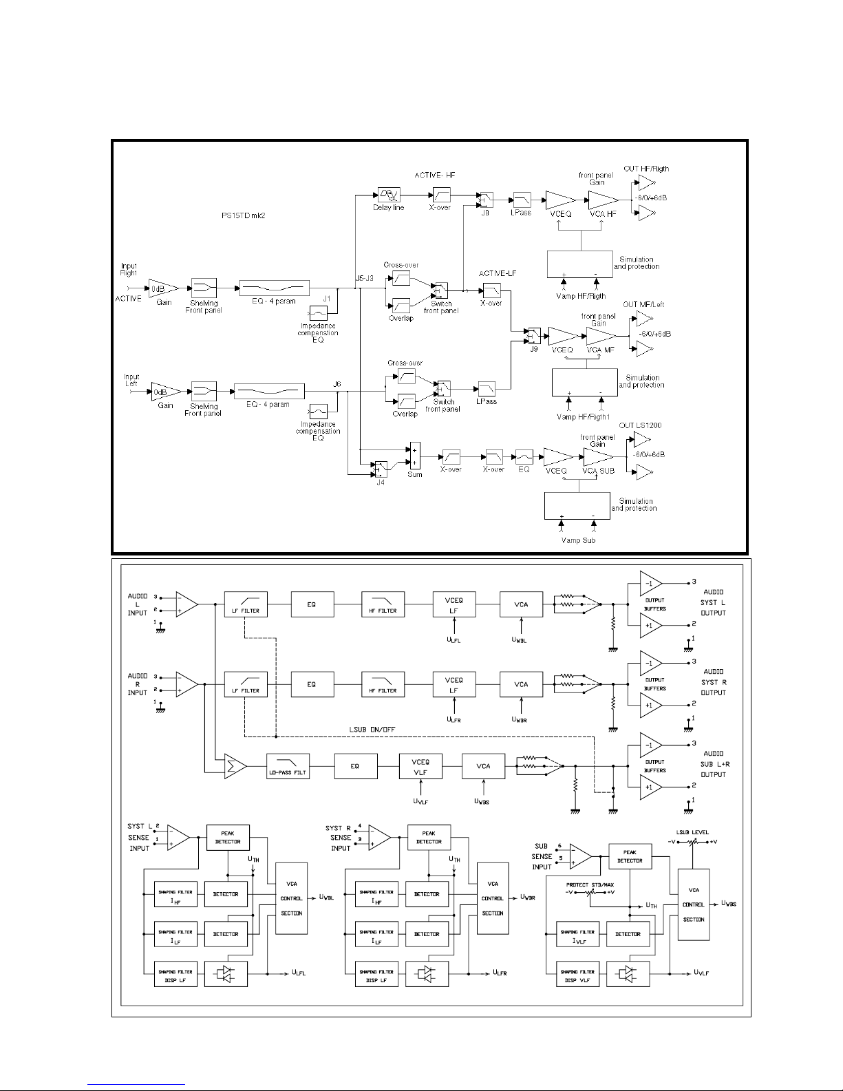
Electronic block diagram
PS8TD & PS10TDcontroller Block Diagramm
Page 26
AMPLIFIERS
___________________________________________________________________________________________________
P.2
6
AMPLIFIERS
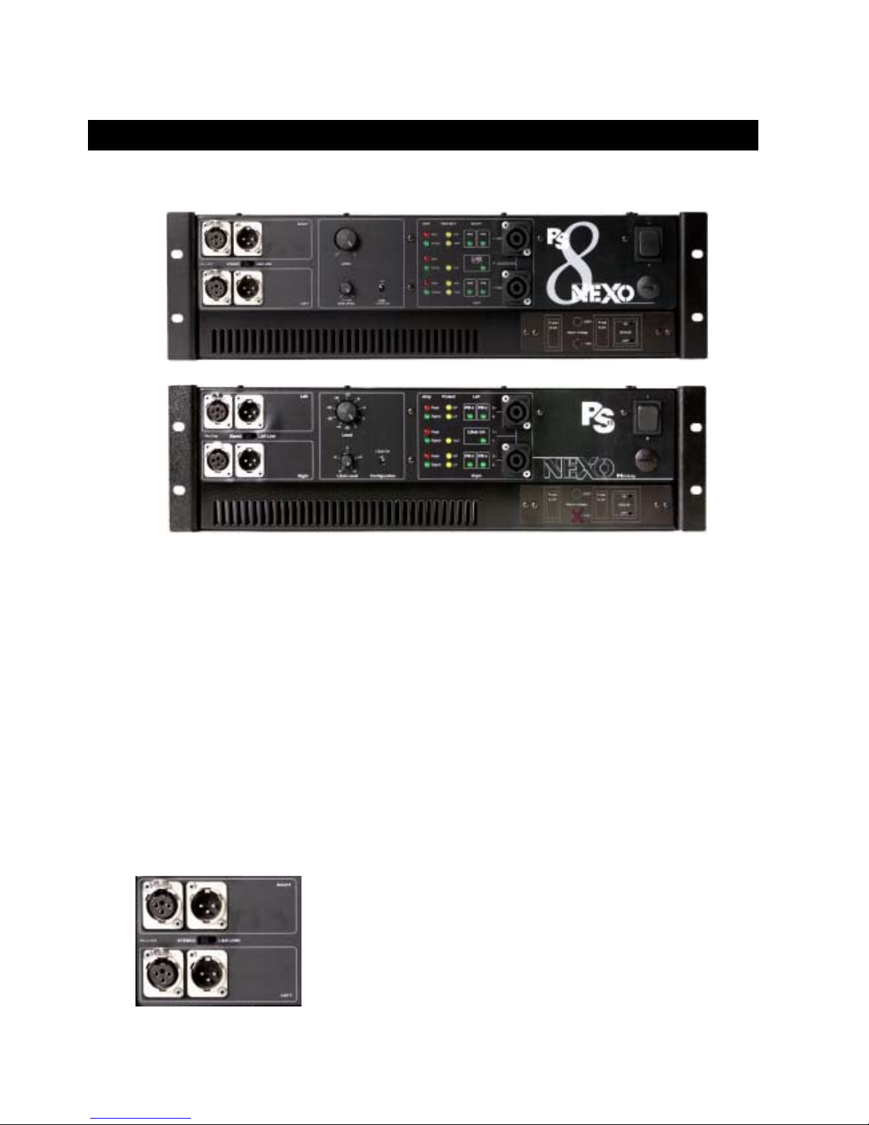
PS8Amp & PS10Amp
The PS8Amp and PS10Amp ar e power amplifiers tailored for PS8 and PS10 s ystem and their respective
LS400 & LS500 sub bass requirements . Their structur e and power being identical, they share the same
specifications:
• Total integration of a T Dcontroller (with internal sense connection) which specific ations are identical of
those of an independent TDcontroller desc ribed in the chapter “T Dcontroller REFERENCE GUIDE” page
23
• 2 or 3 channel instantaneous configuration via front-panel switch, allowing a 3-WAY use with the
appropriate sub bass or a 2 W AY (wideband) configuration. Power delivered by the amplifier is thus
optimized for the proper configuration. Speaker wiring of each cabinet is also automatically re-assigned.
• All connections and controls located on the front panel including mains fuses and voltage selection.
• Super silent, back to front, variable speed fan cooling.
• 3 units high.
Inputs
Each balanced Line Input has a chaining male connector for operation of
multiple PSAmps.
The L&R link switch sim plifies Mono wiring when independent PSAmp stack s
are used for stage Left and Right.
Page 27
AMPLIFIERS
___________________________________________________________________________________________________
P.2
7
Outputs
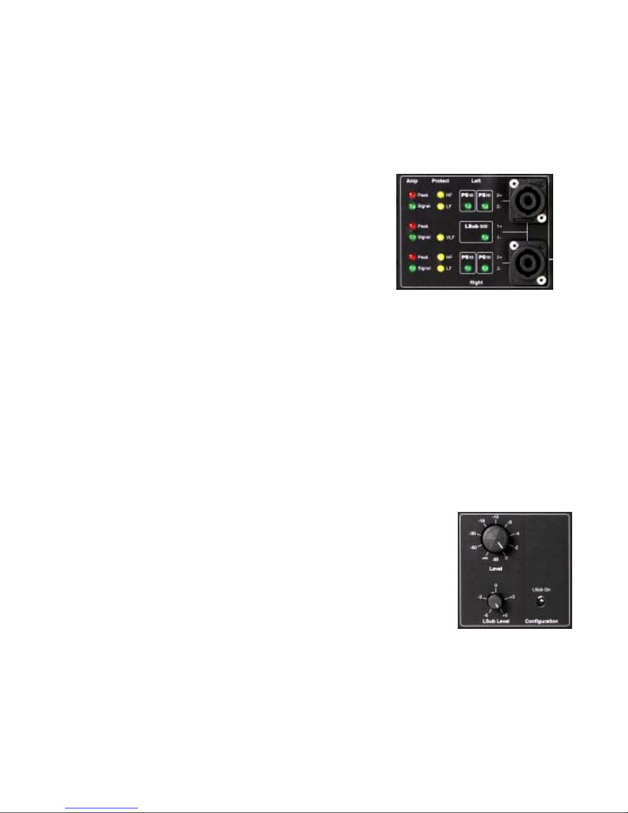
The two Speakon connectors are autom atically configured with a visual indication of the current wiring.
Configuration can be made while the system is operating.
• Sub On = 3 amplifier channels :
The two PS10 Stereo channels ar e assigned to poles 2+ and
2- on the L & R Speakons. A single PS10 LED lights up on
each Stereo channel.
The LSub 500 channel is Mono L+R summed and assigned in
parallel to poles 1+ and 1- of both Speak ons. T he LS500 LED
lights up.
• Sub Off = 2 amplifier channels:
The two PS10 Stereo channels are assigned to poles 2+ and 2- on the L & R Speakons. Two PS10 LEDs
are lighted on each channel. Poles 1+ and 1- of both Speakons are disconnected. The LS500 LED is off.
Sub Bass Channel
The LSub On Switch automatically reconfigures the PSAmp according to its two operating modes :
• Sub On = 3 amplifier channels :
2 x 430 Watts into 8 Ohm channels feed two PS10s in Stereo.
1 x 850 Watts into 4 Ohm channel feeds the LSub 500 in Mono L+R.
• Sub Off = 2 amplifier channels :
2 x 850 Watts into 4 Ohm channels feed two or four PS10s in Stereo.
The 1700 W power capability of the PSAmp is always used whether or not the
LSub is operated. The Sub amplif ier channel is rerouted to the PS10s in the
Sub Off operating mode. In both cases the installation is always stereophonic.
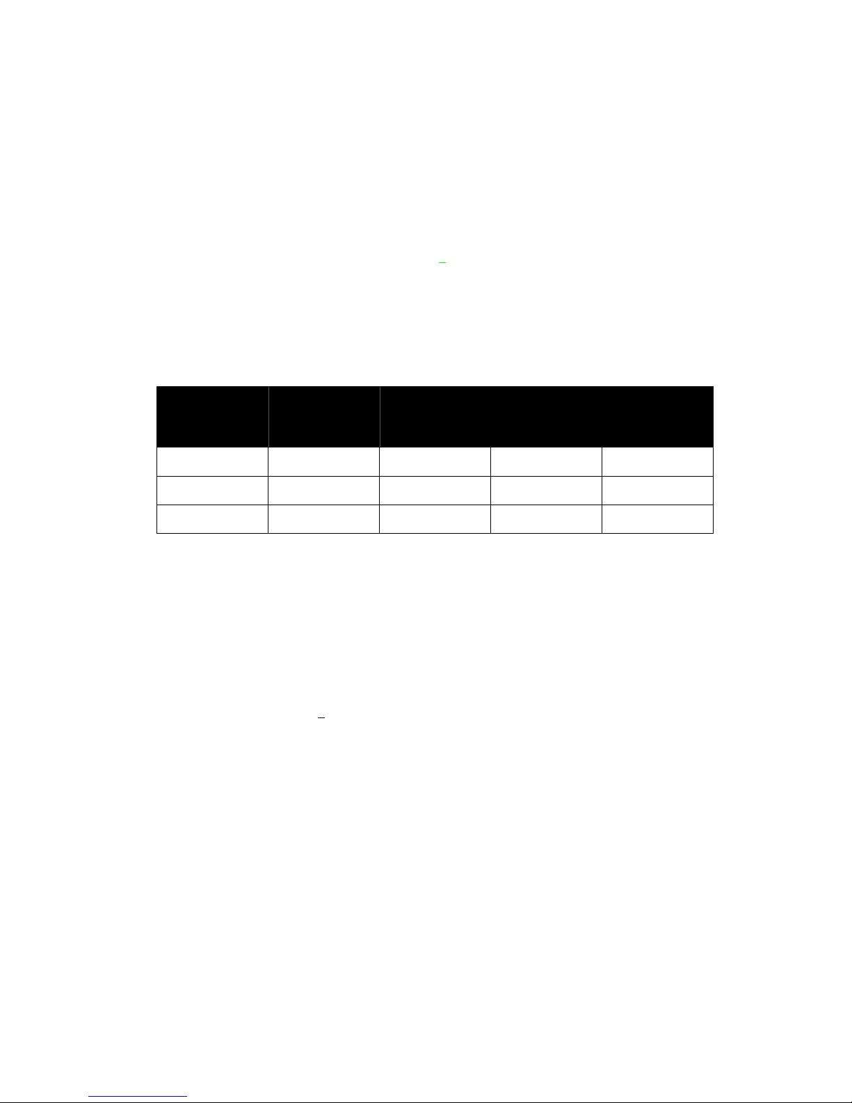
Level control
The Level control operates sim ultaneously on all 2 or 3 channels according to
configuration.
The LSub Level control adjusts the relative level of the LSub relative to the PS
when Sub is On.
It is independent of overall Level control.
Page 28

AMPLIFIERS
___________________________________________________________________________________________________
P.2
8
Fuses and Mains
Mains Voltage selection, safety fuses and Earth-Lif t configuration are located under the safety cover on
the front panel.
The mains power cable c an be loc ated on the front or on the bac k of the PS10Am p. No other c ontrol or
connection exists on the back of the amplifier. At installation nothing else is required than sufficient air flow
path on the back of the PS10Amp.
Stand alone Amplifiers
Recommended Power
NEXO recommends high power amplifiers in all cases, budget constraints being the only reason to select
lower power amplifiers . If a pr oblem occurs on an installation without protection, the use of a lower power
amplifier generating half their rated output power (-3dB) will not prevent possible dam age. This is due to
the fact that the RMS power handling of the weakest component in the system is always 6 to 10 dB lower
than the amps' rating
Current Rating
It is very important that the selected am plifier behaves correctly under low load conditions. A speaker
system is reactive by nature, on transient signals like m usic it will require much higher instantaneous
current than its nominal impedance would indicate (four to ten times more). Amplifiers are usually
specified by their continuous RMS power into resistive loads (which is irrelevant); the only useful
information in that regard is the specification into a 2 ohms load. It is possible to make an amplifier
listening test by loading the amplifier with twice the number of cabinets considered f or the application (2
speakers per channel ins tead of one, 4 instead of 2…) and m odulating at high level ( onset of clipping). If
the signal does not noticeably deteriorate the amplifier is well adapted (overheating after approximately ten
minutes is normal but thermal protection must not operate too quickly after starting this test).
Gain
It is very important to know the voltage gain of all am plifiers present in your set-up. This will ensure the
correct alignment of your system and may be obligatory (for reliability) in cases where only one
TDcontroller drives sever al amps . The tolerance s hould be about ±0,5 dB. In practice this can be difficult
to achieve:
• Some amplifier brands have an identical input sensitivity for models of different power ratings (this means
DIFFERENT VOLTAGE GAIN for each model). This problematic practice, inherited from non-professional
applications, is easily detected when the manufacturer spec if ies the s ame input sensitivity for all its range
(like 775mV/0dBm or 1.55V/+6dBm). This translates into very high gain values on higher power models.
• Other brands do offer c onstant gain, but often only within a given product range (like higher gain on all
semi-professional amps).
• Even if a m anufacturer is aware of this pr oblem and applies the constant gain r ule to all its models, the
value chosen is not necessarily the same as other manufacturers.
• Some manufacturers deliver products where manufacturing tolerance on the same model is ±1dB or
more. W orse, the manufactur er might agree to modify this gain at the custom er’s request without clear
Page 29
AMPLIFIERS
___________________________________________________________________________________________________
P.2
9
and visible identification on the device. Other am ps feature internal gain switches that m ake it difficult to
know the amp gain without measuring or opening it.
In cases where you don't know the gain of your amplifier (or want to check it) please read the following
instructions.
1/ Unplug any cabinet from the amp
2/ With a signal generator feed a sine wave (freq. within the audio range, 1000Hz for example) Amplitude
Vin is not important (1V is rather convenient), u
taking care not to choose a value that will overdrive the
amp input!
3/ Measure the Amplitude Volt at the output of the amp.
Gain = 20 * LOG10(Vout/Vin)
Some examples:
Gain
Vin
20dB 26dB 32dB 37dB (1.4V
sensitivity /
1350Wrms)
0.1V 1V 2V 4V 7.1V
0.5V 5V 10V 20V 35.4V
1V 10V 20V 40V 70.8V
Remember that cons tant sensitivity settings will give you different gain values when the amp Power is
different.
Gain value
NEXO recomm ends low gain amplifier s: +26dB is recomm ended, as it is both adequately low and quite
common. This gain level considerably improves signal to noise ratio and allows all preceding electronic
gear, including the TDcontroller, to operate at an optim um level. Remember that using a higher gain
amplifier will proportionally raise the noise floor level by the same amount.
Advanced protections
Some high-end amplifiers may have some advanced functions similar to those found in the NEXO
TDcontrollers ("loudspeaker offset integration", "limiter", "compressor"...). These functions are not well
adapted to NEXO system requirements and m ay interfere with existing protection within the TDcontroller.
NEXO recommends disabling these functions.
Page 30

PS8, PS8TD & LS400 : SPECIFICATIONS, CURVES & DIAGRAMS
___________________________________________________________________________________________________
P.3
0
PS8, PS8TD & LS400 : SPECIFICA TIONS, CURVES & DIAG RAMS
SYSTEM SPECIFICATIONS
PS8 with PS8 TDcontroller LSub 400 with PS8 TDcontr oller
Frequency Response [a]
69 Hz - 19 kHz ±3dB 43 Hz - 120 Hz ±3dB
Usable Range @-6dB [a]
62 Hz – 20 kHz 40 Hz - 140 Hz
Sensitivity 1W @ 1m [b]
96 dB SPL Nominal - 94 dB SPL Wideband 99 dB SPL Nominal
Nominal Peak SPL @ 1m [b]
122 to 125dB Peak (for 200 to 500 W RMS Amp.) 128 to 131 dB Peak (300 to 700 W RMS Amp. )
HF Dispersion [c]
50° to 100° Hor. x 55° Vert. Rotatable Horn, 4 positions -
Directivity : Q & DI [c]
Q : 10 Nominal DI : 10 dB Nomi nal ( f > 1.8 kHz ) -
Crossover Frequencies
2.5 kHz Passive 120 Hz Active through PS8TD
Nominal Impedance
8 Ohms 6 Ohms
Recommended Amplifiers
200 to 500 Watts into 8 Ohms f or 1 x PS8 per channel
400 to 1000 Watts into 4 Ohms f or 2 x PS8 per channel
300 to 700 Watts into 4 Ohms
SYSTEM OPERATION
Electronic Controller
The PS8 TDcontroller is precisely matched to the PS8 & LS400 cabinets and includes sophisticated protection systems. Using
PS8 & LS400 without a properly connected PS8TD will result in poor sound quality and can damage the components. PS8 &
LS400 can also be used with the NX241 Digital TDcontroller.
Dispersion configuration
After quick-release of the front grille from its fixings, the HF Horn can be rotated in 4 positions for dispersion configuration.
Subbass
The PS8 can be used without optional LS400 Subbass. Active two-way operation with the LS400 is included in the PS8TD.
One LS400 matches 2 x PS8, additional LS400 may be used for enhanced effect.
Speaker Cables
PS8 are wired 2- & 2+ on Speakon connectors, LS400 on 1- & 1+. Loop through Speakons are present on both. Single
identical cables can thus be used to loop t hr ough combinations of up to 2 x PS8 & 1 x LS400 i n no par ticular order.
PRODUCT FEATURES
PS8 LSub 400
Components : LF [VLF]
1 x 8" (20cm) Shielded Neodymium 8 Ohms driver 1 x 12" ( 30cm ) long excursi on 6 O hm dr iver
HF
1 x 1" Shielded Neodymium throat driver + Low Distorsion,
Constant Directivity Asymetrical Dispersion Horn.
-
Height x Width x Depth
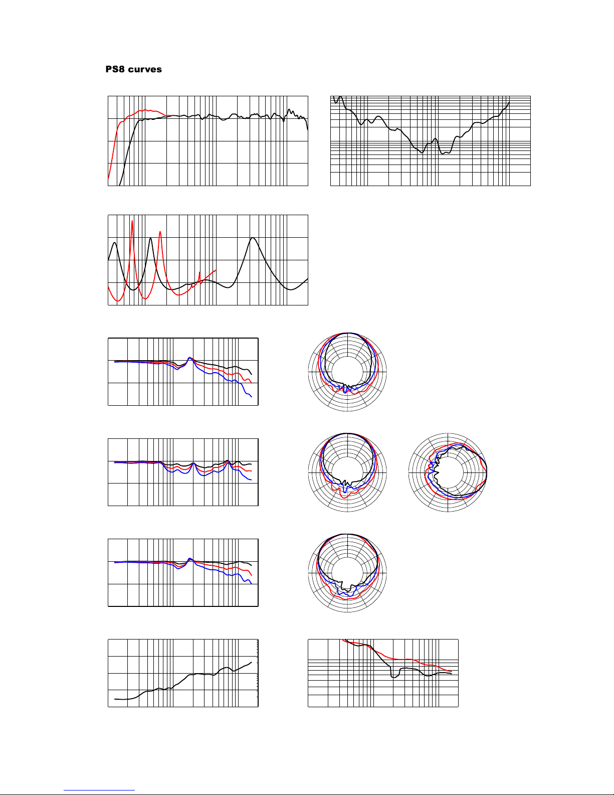
406 x 250 x 219 mm (16"x 9 7/8"x 5 5/8") 338 x 500 x 406 mm (13 1/4’’x 19 5/8’’x 16")
Weight : Net
7.5 kg (16.5 Lb) 19.5 kg (43 Lb)
Connectors
2 x NL4MP SPEAKON 4 pole 2 x NL4MP SPEAKON 4 pole
Construction
Baltic Birch Pl y f inished with structured black coating Baltic Birch Ply & structured black coating
Fittings: Handles
- 2 Metal Handles
Front finish
Perforated steel grille -
Flying Points & Fixed Installation
Threaded inserts are fitted as standard to all cabinet surfaces for
connection of mounting accessories
-
Stand fittings
Built in Stand Fit t ing, 35mm (1"3/8) Internal Stand Fitting on Top (35mm, 1"3/8) accepts a
mast supporting 1 or 2 PS8's.
PRODUCT FEATURES
PS8 TDControll e r
Audio Inputs
Two L&R Audio inputs. Electronically balanced, 36 kOhm. Two XLR-3F connectors.
Sense Inputs
Three Amplifier Sense Inputs (PS8 L&R , LS400). 150 kOhm. 6 Pole Removable Strip Terminal.
Audio Outputs
Two L&R PS8 Audio outputs. Electronically balanced, 50 Ohm. Two XLR-3M.
One Mono (L+R) LS400 A udio output. Electronically balanced, 50 Ohm. One XLR-3M.
Specifications
Output Level : +20 dBm Max. +19dBm Max on 1kOhm
Noise : -88 dBm (22 Hz - 22 kHz, U nWeighted). THD+N : < 0. 03% Ty p. 0.05 Max for +18dBm Output
Controls & Indicators
Std/Max Protection Trimmer. G ain switch (back panel), 3 positions for Amps wit h G ai n : -12 / -6 / 0 dB.
Sub On switch & Sub Gain C ont r ol. Speaker Protect LED's. Amp Sense & Peak LED's.
Power Supply
110/220 Volts (internal w iring), 50/60Hz. Earth-Lift (back panel)
Dimensions & Weight
1U 19" Rack. 190mm (7.5") Depth. 2.9 kg (6.6 Lbs) net
Page 31
PS8, PS8TD & LS400 : SPECIFICATIONS, CURVES & DIAGRAMS
___________________________________________________________________________________________________
P.31
SHIPPING & ORDERING
Packaging
PS8's are packaged as pairs with or w ithout PS8TD in a single box.
Shipping weight & Volume
2 x PS8.U = 16 Kg (35.28 lb.) 0.109 cu m (3.85 cu feet).
2 x PS8.U + 1 x PS.8TD = 19.00 Kg (6.61 lb.) 0.109 cu m (3.85 cu feet ) .
LS.400 = 22 kg (48.5 lb.) 0.130 cu m (4. 59 cu feet).
Accessories
A full selection of mounting Accessories is available, please contact your Nexo Agent for details.
As part of a policy of continual improvement, NEXO reserves the right to change specifications without notice.
[a] Response curves & data : Anechoïc Far Field for the PS8 + PS8TD. Half-Space Anechoïc radiation for the LS400 + PS8TD.
[b] Sensitivity & Pea k SPL da ta : the se will depend on spectral distribution and crest factor of program material. Measured with band limited Pink Noise. Nominal refers to
Voice Decade (300 Hz - 3 kHz), Wideband to the specified ±3dB range. Data are for speaker + processor + recommended amplifier combinations. Peak SPL is at
clipping of recommended amplifier.
[c] Directivity curves & data : obtained by computer treatment on off axis response curves.
Dimensions
Page 32
PS8, PS8TD & LS400 : SPECIFICATIONS, CURVES & DIAGRAMS
___________________________________________________________________________________________________
P.32
30 100 1k 10k 20k
30
20
10
0
10
ON AXIS RESPONSE (dB)
30 100 1k 10k 20k
0.1%
1%
10%
TOTAL DISTORTION (%)
30 100 1k 10k 20k
4
8
16
32
64
IMPEDANCE (Ohms)
100 1k 10k 20k
20
10
0
10
OFF AXIS RESPONSE (dB)
100 1k 10k 20k
20
10
0
10
OFF AXIS RESPONSE (dB)
100 1k 10k 20k
20
10
0
10
OFF AXIS RESPONSE (dB)
100 1k 10k 20k
0
5
10
15
20
1
10
100
DIRECTIVITY INDEX (dB) & Q
100 1k 10k 20k
20˚
100˚
200˚
COVERAGE ANGLE (Degree)
0˚
30˚
60˚
90˚
120˚
150˚
180˚
210˚
240˚
270˚
300˚
330˚
0˚
30˚
60˚
90˚
120˚
150˚
180˚
210˚
240˚
270˚
300˚
330˚
0˚
30˚
60˚
90˚
120˚
150˚
180˚
210˚
240˚
270˚
300˚
330˚
0˚
30˚
60˚
90˚
120˚
150˚
180˚
210˚
240˚
270˚
300˚
330˚
On Axis Responses PS8 & PS8 + LS400. PS8+LS400 : THD for 110dBSPL @ 1m.
Impedances PS8 & LS400.
Horizontal Plane, Vertical Orientation +25˚.
10˚(black), 20˚(Red), 30˚(Blue) off axis response.
Horizontal Plane, Vertical Orientation 0˚.
20˚(black), 30˚(Red), 40˚(Blue) off axis response.
Horizontal Plane, Vertical Orientation -25˚.
30˚(black), 40˚(Red), 50˚(Blue) off axis response.
Directivity Index and Factor. Horizontal (light) and Vertical (black) Coverage Angles, -6dB point.
All measurements made with PS8TDcontroller.
Response curves : Far Field, Halfspace below 200Hz, anechoic above 200Hz.
Off axis response and polar plot : 1/3 octave averaged anechoic measurements.
Vertical orientations refer to the cabinet in front of house configuration.
Directivity index and factor : computer treatment of polar plots.
Horizontal polar plot (left). 5dB/division.
Upper plot : vertical orientation +25˚.
Center plot : vertical orientation 0˚.
Lower plot : vertical orientation -25˚.
Above : vertical Polar plot. 5dB/division.
2 500 Hz Red
5 000 Hz Blue
10 000 Hz Black
Page 33

PS10, PS10TD & LS500 : SPECIFICATIONS, CURVES & DIAGRAMS
___________________________________________________________________________________________________
P.3
3
PS10, PS10TD & LS500 : SPECIFICA TIONS, CURVES & DIAG RAMS
SYSTEM SPECIFICATION S PS10 with PS10 TDcontroller LSub 500 with PS10 TDcontroller
Frequency Response [a] 65 Hz - 20 kHz ±3dB 40 Hz - 110 Hz ±3dB
Usable Range @-6dB [a] 58 Hz - 21 kHz 38Hz - 120 Hz
Sensitivity 1W @ 1m [b] 98 dB SPL Nominal - 96 dB SPL Wideband 101 dB SPL Nominal
Nominal Peak SPL @ 1m [b] 124 to 127 dB Peak (for 200 to 500 W RMS Amp.) 131 to 134 dB Peak (300 to 800 W RMS Amp.)
HF Dispersion [c] 50° to 100° Hor. x 55° Vert. Rotatable Horn, 4 positions Directivity : Q & DI [c] Q : 16 Nominal DI : 12 dB Nominal ( f > 3 kHz ) Crossover Frequencies 2 kHz Passive 120 Hz Active through PS10 TD
Nominal Impedance 8 Ohms 4 Ohms
Recommended Amplifiers 200 to 500 Watts into 8 Ohms for 1 x PS10 per channel 400
to 1000 Watts into 4 Ohms for 2 x PS10 per channel
300 to 800 Watts into 4 Ohms
SYSTEM OPERATION
Electronic Controller The PS10 TDController is precisely matched to the PS10 & LS500 cabinets and includes sophisticated protection
systems. Using PS10 & LS500 without a properly connected PS10 TD will result in poor sound quality and can
damage the components.
Dispersion configuration After quick-release of the front grille from its fixings, the HF Horn can be ro tated in 4 positions for dispersion
configuration.
Subbass The PS10 can be used without optional LS500 Subbass. Active two-way operation with the LS500 is included in
the PS10 TD. One LS500 matches 2 x PS10, additional LS500 may be used for enhanced effect.
Speaker Cables PS10 are wired 2- & 2+ on Speakon connectors, LS500 on 1- & 1+. Loop through Speakons are present on both.
Single identical cables can thus be used to loop through combinations of up to 2 x PS10 & 1 x LS500 in no
particular order.
PRODUCT FEATURES PS10 LSub 500
Components : LF [VLF] 1 x 10" (25cm) 8 Ohm driver 1 x 15" (38cm) long excursion 4 Ohm driver
HF 1 x 1" throat driver + Low Distorsion,
Constant Directivity Asymetrical Dispersion Horn.
-
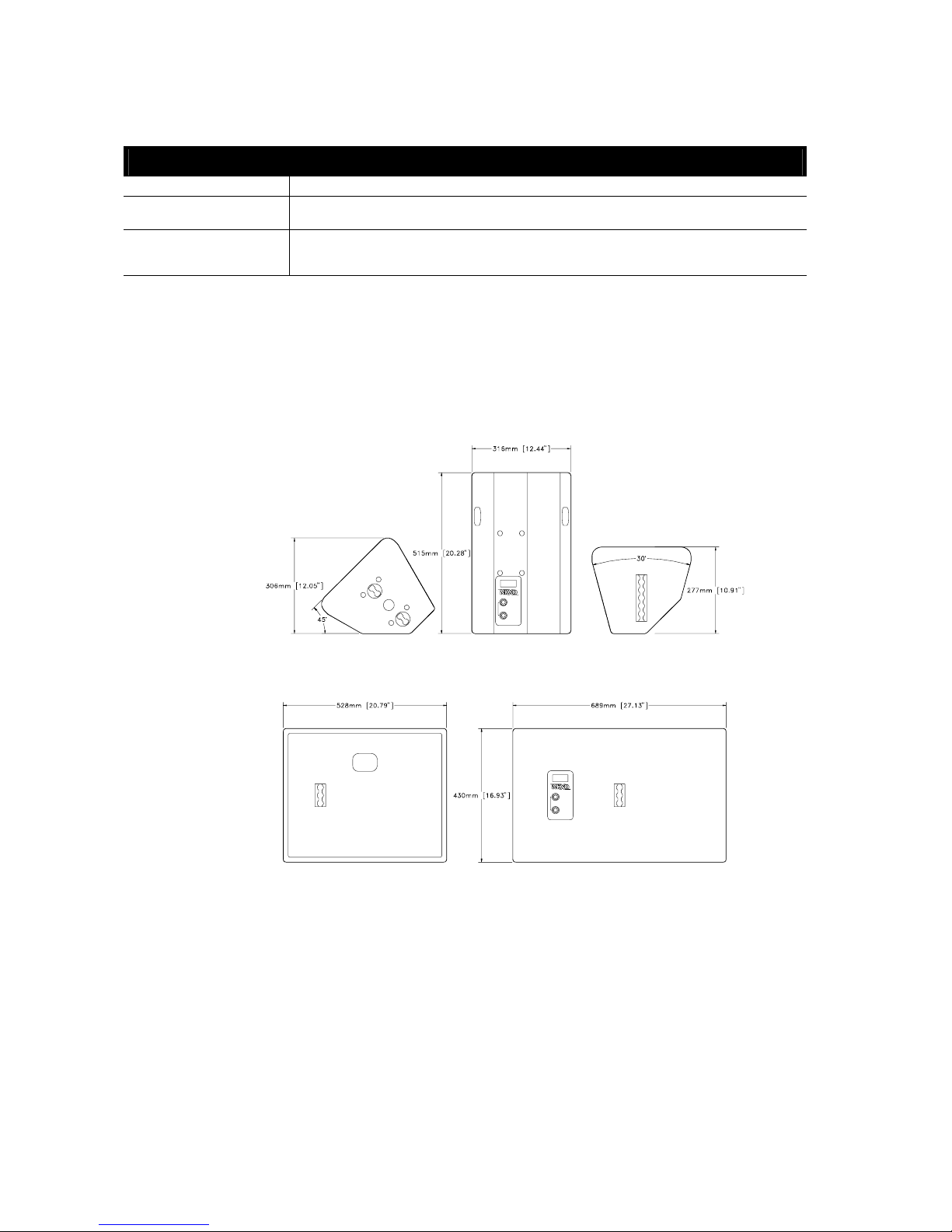
Height x Width x Depth 515 x 316 x 277 mm (20.28"x 12.44"x 10.91") 430 x 689 x 528 mm (16.93"x 27.13"x 20.79")
Weight : Net 15 kg (33 Lbs) 33 kg (73 Lbs)
Connectors 2 x NL4MP Speakon 4 pole 2 x NL4MP Speakon 4 pole
Construction Baltic Birch Ply finished with structured black coating Baltic Birch Ply & structured black coating
Fittings: Handles 2 Metal recessed pockets 2 Metal recessed pockets
Front finish Acoustic foam on hex perforated steel grille (77% transparent) Perforated steel grilles
Flying Points 1 steel anchor plate for flying track on top (6 positions).
2 steel anchor plates for flying tracks on bottom (1 position)
3 steel anchor plates for flying
tracks on sides and back
Stand fittings Built in Steel Stand Fitting, 35mm (1"3/8) Internal Steel Stand Fitting on Top (35mm,
1"3/8) accepts a mast supporting 1 or 2 PS10's.
Fixed Installation Two sets of 4 fixing points (Omnimount 100 Std spacing)
for Horizontal or Vertical installation.
-
PRODUCT FEATURES PS10 TDController
Audio Inputs Two L&R Audio inputs. Electronically balanced, 36 kOhm. Two XLR-3F connectors.
Sense Inputs Three Amplifier Sense Inputs (PS10 L&R, LS500). 150 kOhm. 6 Pole Removable Strip Terminal.
Audio Outputs Two L&R PS10 Audio outputs. Electronically balanced, 50 Ohm. Two XLR-3M.
One Mono (L+R) LS500 Audio output. Electronically balanced, 50 Ohm. One XLR-3M.
Specifications Output Level : +20 dBm Max. +19dBm Max on 1kOhm
Noise : -88 dBm (22 Hz - 22 kHz, UnWeighted). THD+N : < 0.03% Typ. 0.05 Max for +18dBm Output
Controls & Indicators Std/Max Protection Trimmer. Gain switch (back panel), 3 positions for Amps with Gain : 26 / 32 / 38 dB.
Sub On switch & Sub Gain Control. Speaker Protect LED's. Amp Sense & Peak LED's.
Power Supply 110/220 Volts (internal wiring), 50/60Hz. Earth-Lift (back panel)
Dimensions & Weight 1U 19" Rack. 190mm (7.5") Depth. 2.9 kg (6.6 Lbs) net
Page 34
PS10, PS10TD & LS500 : SPECIFICATIONS, CURVES & DIAGRAMS
___________________________________________________________________________________________________
P.3
4
SHIPPING & ORDERING
Packaging PS10's are packaged as pairs with PS10TD (Ref: PS10P+T) or without PS10TD (Ref : PS10P) in a single box.
Shipping weight & Volume Ref PS10P : 34 Kg (pair). Ref PS10P+T : 37 Kg (pair+processor). Shipping Volume : 0.169 m3 ( 5.96 cu feet)
Ref LS500 : 38 kg (unit) 0.238 m3 (8.41 cu feet)
Accessories Flying Kit (Ref: FLYPS10) containing 1 x PS10 Top Rail, 2 x PS10 Bottom Rails, 4 x Single Stud Flying Rings.
Mast Adapter Kit (Ref: STDUPS10) containing 1 m (39") long mast & U coupler supporting 1 or 2 PS10 above
LS500
As part of a policy of continual improvement, NEXO reserves the right to change specifications without notice.
[a] Response curves & data : Anechoïc Far Field for the PS10 + PS10TD. Half-Space Anechoïc radiation for the LS500 + PS10TD.
[b] Sensitivity & Peak SPL data : these will depend on spectral distribution and crest factor of program material. Measured with band limited Pink Noise. Nominal
refers to Voice Decade (300 Hz - 3 kHz), Wideband to the specified ±3dB range. Data are for speaker + processor + recommended amplifier combinations. Peak
SPL is at clipping of recommended amplifier.
[c] Directivity curves & data : obtained by computer treatment on off axis response curves.
Omnimount is a registered trade mark of Omnimount Systems Inc.
Dimensions
Page 35
PS10, PS10TD & LS500 : SPECIFICATIONS, CURVES & DIAGRAMS
___________________________________________________________________________________________________
P.3
5
16037 Hz
10085 Hz
5086 Hz
0°
180°
90° 90°
30°
30°
60°60°
120° 120°
150° 150°
0°
180°
90° 90°
30°30°
60°60°
120° 120°
150° 150°
0°
180°
90° 90°
30°30°
60°60°
120° 120°
150° 150°
0°
30°
90°
60°
60°
90°
120°
150°
180°
150°
120°
30°
16037 Hz
10085 Hz
5086 Hz
16037 Hz
10085 Hz
5086 Hz
16037 Hz
10085 Hz
5086 Hz
PS10 Curves
30 100 1k 10k 20k
-30.00
-20.00
-10.00
0.0
10.000
ON AXIS RESPONSE (dB)
c 1 : On axis responses PS10 & PS10 + LS500
30 100 1k 10k 20k
0.1
1
10
TOTAL DISTORSION (%)
c 2 : PS10 + LS500 : THD for 110 dBSPL @ 1m.
30 100 1k 10k 20k
6.0000
12.000
18.000
24.000
30.000
IMPEDANCE (Log Z)
c 3 : Impedance PS10 and LS500
100 1k 10k 20k
-20.00
-10.00
0.0
10.000
OFF-AXIS RESPONSE (dB)
c 4 : Horizontal plane, vertical orientation +25°. 10°(black),20°(light),30°(dark)
off axis response
100 1k 10k 20k
-20.00
-10.00
0.0
10.000
OFF-AXIS RESPONSE (dB)
c 5 : Horizontal plane, vertical orientation 0°. 20°(black),30°(light),40°(dark)
off axis response
100 1k 10k 20k
-20.00
-10.00
0.0
10.000
OFF-AXIS RESPONSE (dB)
c 6 : Horizontal plane, vertical orientation -25°. 30°(black),40°(light),50°(dark)
off axis response
-Horizontal polar plots (left)
upper plot : vertical orientat i on +25°
center plot : vertical ori entation 0°
lower plot : vertical ori ent ation -25°
-Vertical polar plot (right)
5 dB / div
100 1k 10k 20k
1
10
100
0.0
5.0000
10.000
15.000
20.000
DIRECTIVITY INDEX (dB) & Q
c7 : Directivity index and factor.
100 1k 10k 20k
20
100
200
COVERAGE ANGLES (ł)
c 8 : Horizontal (light) and vertical (black) coverage angles, -6dB points.
Page 36
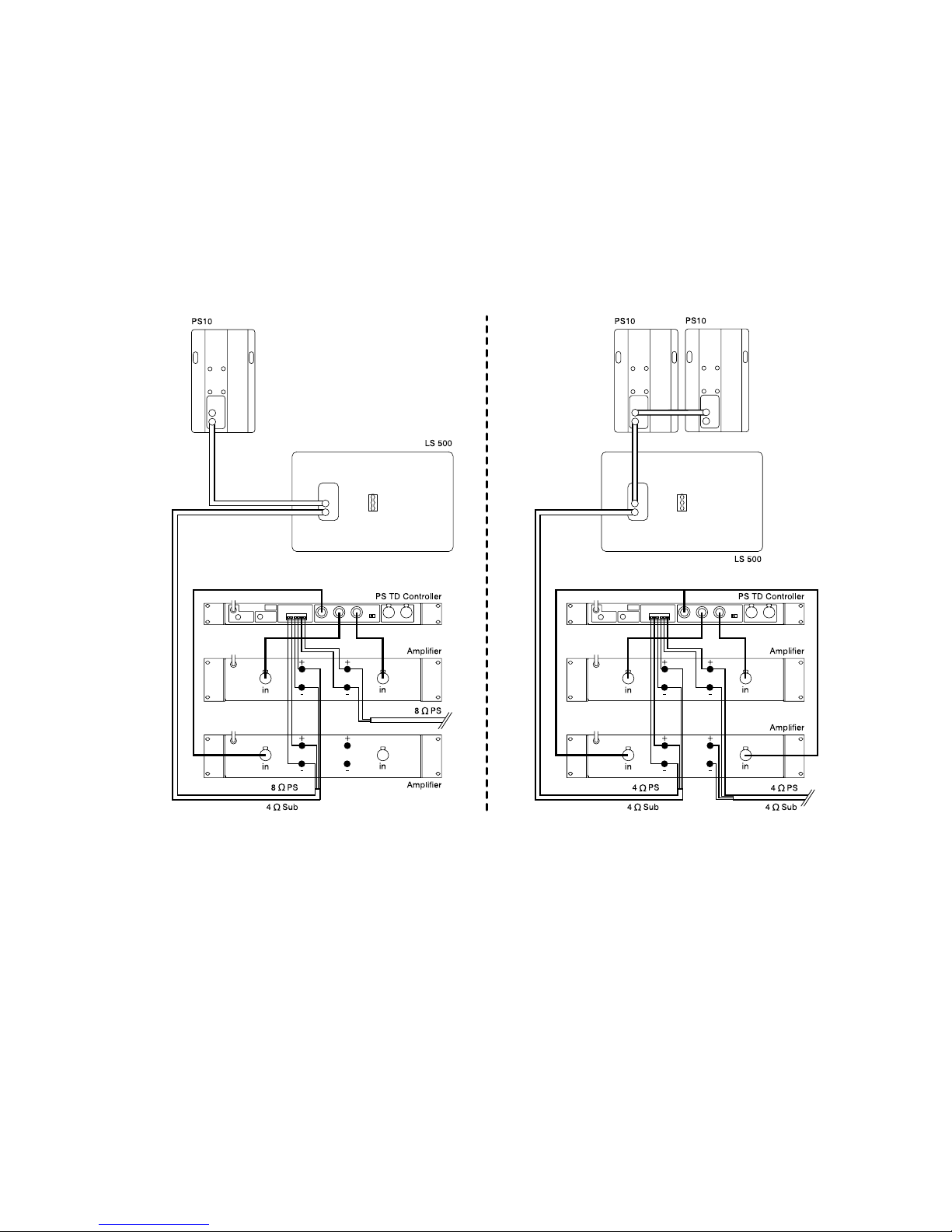
PS10, PS10TD & LS500 : SPECIFICATIONS, CURVES & DIAGRAMS
___________________________________________________________________________________________________
P.3
6
Connection Diagrams
Page 37

PS15, PS15TD MKII & LS1200 : SPECIFICATIONS, CURVES & DI AGRAM S
___________________________________________________________________________________________________
P.3
7
PS15, PS15TD MKII & LS1200 : SPECIFICA TIONS, CURVES & DIAG RAMS
SYSTEM SPECIFICATION S PS15 with PS15 TDcontroller MK2 LSub 1200 with PS15 TDcontroller MK2
Frequency Response [a] 50 Hz - 18 kHz ±3 dB 30 Hz - 120 Hz ±3 dB
Usable Range @-6 dB [a] 47 Hz - 18 kHz 29 Hz - 130 Hz
Sensitivity 1W @ 1m [b] 102 dB SPL Nominal. 99 dB SPL Wideband 102 dB SPL Nominal
Nominal Peak SPL @ 1m [b] 131 to 134 dB Peak (for 550 to 1200 W RMS Amp.) 133 to 135 dB Peak (800 to 1200 W RMS Amp.)
HF Dispersion [c] 50° to 100° Hor. x 55° Vert. Rotatable Horn - 4 positions Directivity : Q & DI [c] Q : 16 Nominal DI : 12 dB Nominal ( f > 1.5 kHz ) Crossover Frequencies 900 Hz Passive or Active (internally switchable) 80 Hz Active through PS15 TD
Nominal Impedance Passive : 8 Ohms or Active : LF : 6 Ohms & HF : 8 Ohms 6 Ohms
Recommended Amplifiers 550 to 1200 Watts into 8 Ohms for 1 x PS15 per channel
1000 to 1800 Watts into 4 Ohms for 2 x PS15 per channel
800 to 1200 Watts into 8 Ohms
-
SYSTEM SPECIFICATION S PS15Bass with PS15 TDcontroller
Frequency Response 40 Hz - 300 Hz
Sensitivity 1W @ 1m 102 dB SPL Nominal. 99 dB SPL Wideband
Nominal Peak SPL @ 1m 131 to 134 dB Peak (for 550 to 1200 W RMS Amp)
Cutoff Frequency 120 Hz Passive - 6dB per Octave - Reactance compensation
Nominal Impedance 8 Ohms
Recommended Amplifiers 550 to 1200 Watts into 8 Ohms for 1 x PS15Bass per channel
1000 to 1800 Watts into 4 Ohms for 1 x PS15Bass + 1 x PS15 or 2 x PS15Bass per channel
SYSTEM OPERATION
Electronic Controller The PS15 TDcontroller is precisely matched to the PS15 & LS1200 cabinets and includes protections. Using
PS15 & LSub’s without a properly connected PS15 TD will result in poor sound quality and can damage the
components.
Dispersion configuration After quick-release of the front grille from its fixings, the HF Horn can be ro tated in 4 positions for dispersion
configuration.
Subbass The PS15 can be used without optional Subbass. Active operation of the LS1000 is included in the PS15 TD.
Speaker Cables PS15 are wired 2- & 2+ on Passive Input Speakons, LS1000 on 1- & 1+. Loop through Speakons are present on
both. Single identical cables can thus be used to loop through combinations of PS15 in passive & LS1000 in no
particular order.
PRODUCT FEATURES PS15 LSub 1200
Components :LF [Sub]
HF
1 x 15" (38 cm) 6 Ohms proprietary
1 x 2" throat, 3" Titanium diaphragm, driver + Low Distortion,
Constant Directivity Asymmetrical Dispersion Horn.
1 x 18" (46 cm) long excursion 6 Ohm
proprietary driver
-
Height x Width x Depth 675 x 434 x 368 mm (26.57"x 17.08"x 14.48") 515 x 791 x 597 mm (20.28"x 31.14"x 23.50")
Dimensions of 2 stacked LS1200 = 1 x LS2000
Weight : Net 29 kg (64 Lb.) 45 kg (99 Lb.)
Speakon Connectors 2 x 4 pole (Passive In & Loop Thru) + 1 x 4 Pole (Active In) 2 x 4 pole (In & Loop Thru)
Construction Baltic Birch Ply finished with structured black coating Baltic Birch Ply & structured black coating
Fittings: Handles 2 Metal recessed pockets 2 Metal recessed pockets
Front finish Acoustic foam on hex perforated steel grille (77% transparent) Perforated steel grilles
Flying Points 1 steel anchor plate for flying track on top (9 positions).
2 steel anchor plates for flying tracks on bottom (3 positions)
3 steel anchor plates for flying tracks on sides
and back
Stand fittings Built in Steel Stand Fitting, 35 mm (1"3/8) Internal Steel Stand Fitting on Top (35 mm,
1"3/8) accepts a mast supporting 1 or 2 PS15's.
Fixed Installation One set of 4 fixing points (Omnimount 100 Std spacing)
Page 38
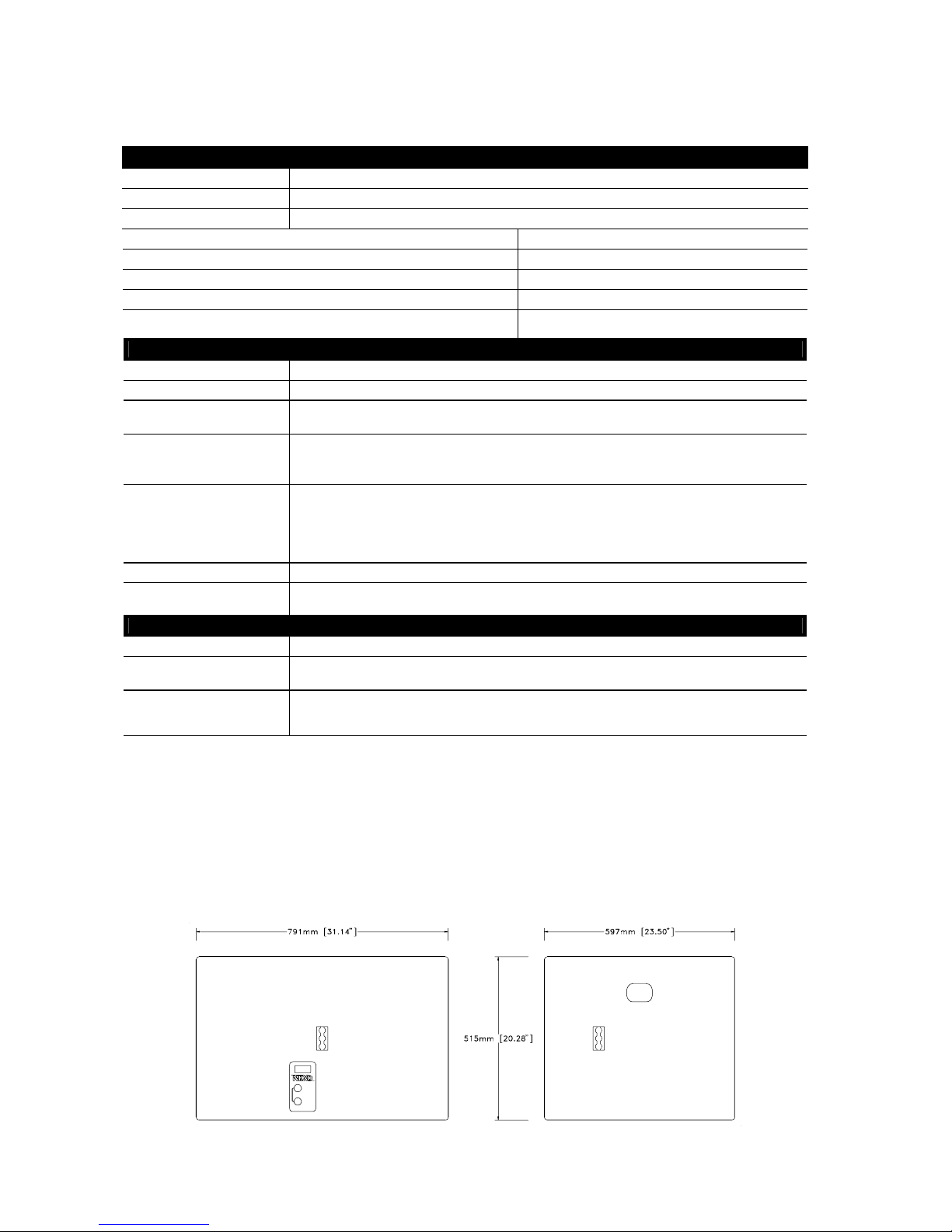
PS15, PS15TD MKII & LS1200 : SPECIFICATIONS, CURVES & DI AGRAM S
___________________________________________________________________________________________________
P.3
8
PRODUCT FEATURES PS15Bass
Components :. 1 x 15" (38 cm) proprietary. Identical to the PS15 LF unit
Height x Width x Depth. 675 x 434 x 457 mm (26.57"x 17.08"x 17.99")
Weight : Net 26 kg (57 Lb)
Speakon Connectors 2 x 4 poles (Passive In & Loop Thru) + 1 x 4 pole (Active)
Construction Baltic Birch Ply finished with structured black coating
Fittings : Handles 2 Metal Handles
Front Finish Acoustic foam on Hex perforated steel grille (77 % tra nsparent)
Flying Points 1 steel anchor plate for flying track on bottom (9 positions).
2 steel anchor plates for flying tracks on top (3 positions).
PRODUCT FEATURES PS15 TDcontroller MK2
Audio Inputs Two L&R Audio inputs. Electronically balanced, 50 kOhm. Two XLR-3F connectors.
Sense Inputs Three Amplifier Sense Inputs (PS15 L&R, LS1200). 180 kOhm. on 6 Pole Removable Strip Terminal.
Audio Outputs Two L&R (HF&LF in active mode) PS15 Audio outputs. Electronically balanced, 50 Ohm. On two XLR-3M.
One Mono (L+R) LS1200 Audio output. Electronically balanced, 50 Ohm.
Specifications
Output Level : +28 dBu Max on 600Ω - 1nF load.
Noisefloor (22 Hz - 22 kHz, Unweighted, output level 0dB) L&R: -90 dBm, Sub : -70 dBm.
THD+N : < 0.03% Typ. 0.05% Max. for +20 dBm Output
Controls & Indicators Front panel : Overlap / Crossover switch, Speaker Protect LED's, Amp Sense & Peak LED's, Bass EQ
trimmers (+/- 3dB). 3 Peak limiters adj. trimmers, one gain control trimmer per channel.
Back panel : Gain switch -6/0/+6 dB.
Internal : 3 protection trimmers. Switching Active/Passive.
Power Supply 115/230 Volts (switch on back panel), 50/60 Hz. Earth-Lift (switch on back panel)
Dimensions & Weight 1U 19" Rack. 210 mm (8.5") Depth. 3.3 kg 7.3 (Lb.) net
SHIPPING & ORDERING
Packaging PS15's are sold as pairs with PS15TD
Shipping weight & Volume PS15 : 32 Kg (70 lb.) 0.2 cum (7 cu feet). PS15 TD : 3.85 Kg (8.47 lb.) 0.02 cu m (0.6 cu feet)
Ref. LS1200 : 49 kg (108 lb.)0.32 cu m (11 cu feet)
Accessories Flying Kit (Ref.: FLYPS15) containing 1 x PS15 Top Rail, 2 x PS15 Bottom Rails, 4 x Single Stud Flying Rings.
Mast Adapter Kit (Ref.: STDUPS15) containing 1 m (39") long mast & U coupler supporting 1 or 2 PS15 above
LS1000.
As part of a policy of continual improvement, NEXO reserves the right to change specifications without notice.
[a] Response curves & data : Anechoic Far Field for the PS15 + PS15TD. Half-Space Anechoic radiation for the LS1000 + PS15TD.
[b] Sensitivity & Peak SPL data : these will depend on spectral distribution and crest factor of program material. Measured with band limited Pink Noise.
Nominal refers to Voice Decade (300 Hz - 3 kHz), Wideband to the specified ±3 dB range. Data are for speaker + processor + recommended amplifier
combinations. Peak SPL is at clipping of recommended amplifier. Measurements made with PS15's in passive operation mode.
[c] Directivity curves & data : obtained by computer treatment on off axis response curves.
Omnimount is a registered trade mark of Omnimount Systems Inc.
Dimensions
Page 39
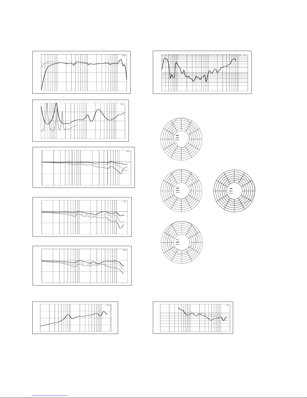
PS15, PS15TD MKII & LS1200 : SPECIFICATIONS, CURVES & DI AGRAM S
___________________________________________________________________________________________________
P.3
9
0°
180°
90° 90°
30°
30°
60°60°
120° 120°
150° 150°
0°
180°
90° 90°
30°30°
60°60°
120° 120°
150° 150°
0°
180°
90° 90°
30°30°
60°60°
120° 120°
150° 150°
0°
30°
90°
60°
60°
90°
120°
150°
180°
150°
120°
30°
10000 Hz
5000 Hz
2500 Hz
10000 Hz
5000 Hz
2500 Hz
10000 Hz
5000 Hz
2500 Hz
10000 Hz
5000 Hz
2500 Hz
PS15 : Curves
30 100 1k 10k 20k
-30.00
-20.00
-10.00
0.0
10.000
ON AXIS RESPONSE (dB)
c 9 : On axis responses PS15 & PS15 + LS1000
30 100 1k 10k 20k
0.1
1
10
TOTAL DISTORSION (%)
c 10 : PS15 + LS1000 : THD for 115 dBSPL @ 1m.
30 100 1k 10k 20k
2 Ohm
4 Ohm
8 Ohm
16 Ohm
32 Ohm
IMPEDANCE
c 11 : Impedance PS15 and LS1000
100 1k 10k 20k
-20.00
-10.00
0.0
10.000
OFF-AXIS RESPONSE (dB)
c 12 : Horizontal plane, vertical orientation +25°. 10°(black),20°(light), 30°(dark)
off axis response
100 1k 10k 20k
-20.00
-10.00
0.0
10.000
OFF-AXIS RESPONSE (dB)
c 13 : Horizontal plane, vertical orientation 0°. 20°(black),30°(light),
40°(dark) off axis response
100 1k 10k 20k
-20.00
-10.00
0.0
10.000
OFF-AXIS RESPONSE (dB)
c 14 : Horizontal plane, vertical orientation -25°. 30°(black),
40°(light),50°(dark) off axis response
-Horizontal polar plots (left)
upper plot : vertical orientat i on +25°
center plot : vertical ori entation 0°
lower plot : vertical ori ent ation -25°
-Vertical polar plot (right)
5 dB / div
100 1k 10k 20k
1
10
100
0.0
5.0000
10.000
15.000
20.000
DIRECTIVITY INDEX (dB) & Q
c15 : Directivity index and factor
100 1k 10k 20k
20
100
200
COVERAGE ANGLES (Degree)
c 16 : Horizontal (light) and vertical (black) coverage angles, -6dB points.
Page 40
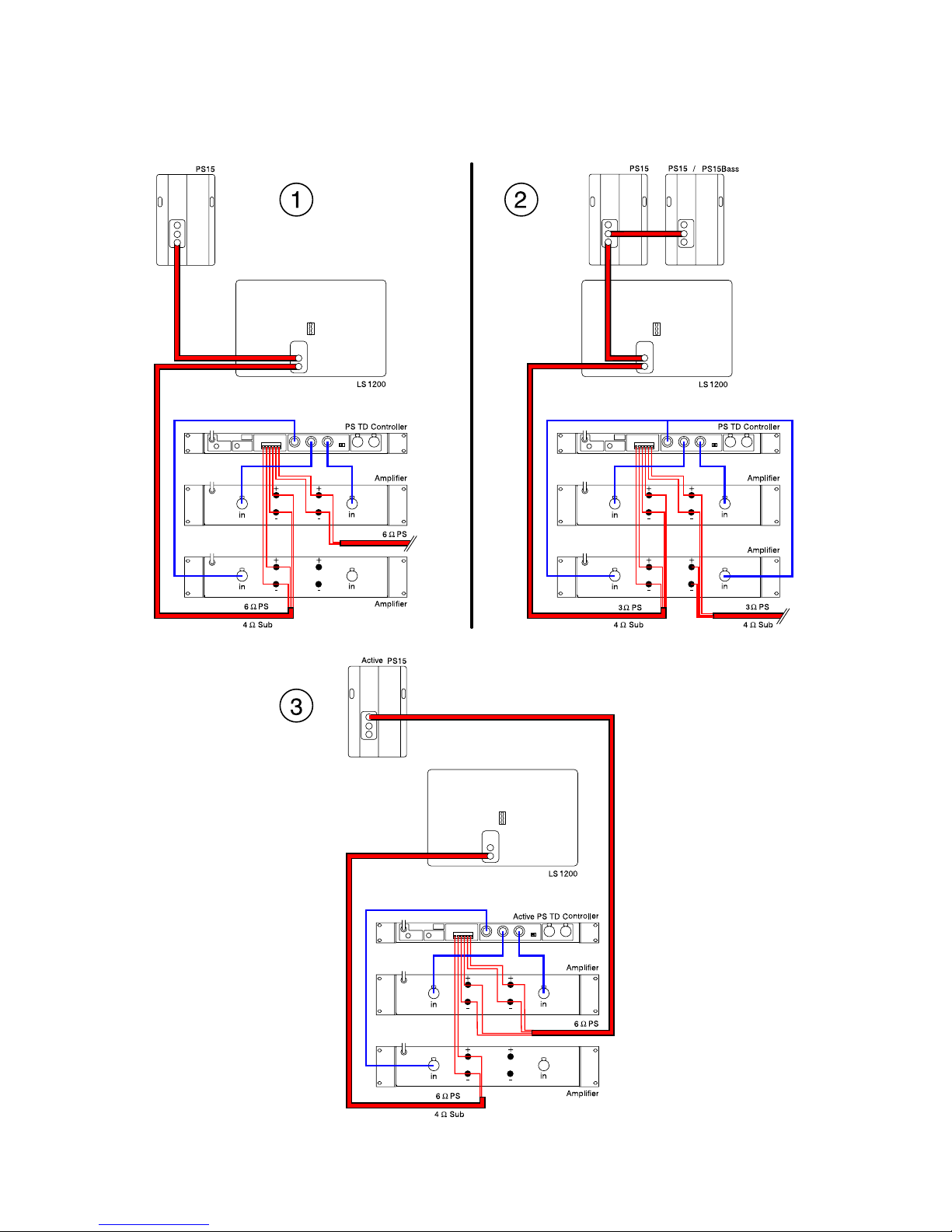
PS15, PS15TD MKII & LS1200 : SPECIFICATIONS, CURVES & DI AGRAM S
___________________________________________________________________________________________________
P.4
0
Connection Diagrams
Page 41

Page 42
 Loading...