

Page 1

DPU
DPU ““““Digital
DPU DPU
Digital Patching Unit
Digital Digital
QUICK START v1.2
Patching Unit””””
Patching UnitPatching Unit
Page 2
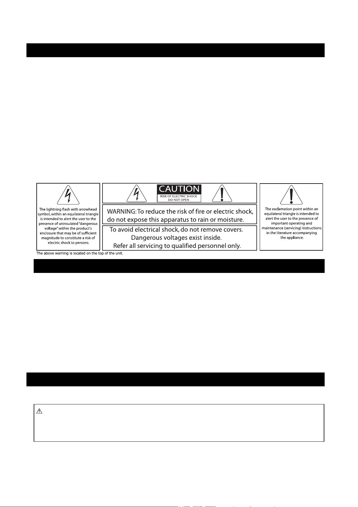
FCC INFORMATION (U.S.A.)
1. IMPORTANT NOTICE: DO NOT MODIFY THIS UNIT!
This product, when installed as indicated in the instructions contained in this
manual, meets FCC requirements. Modifications not expressly approved by
NEXO-SA may void your authority, granted by the FCC, to use the product.
2. IMPORTANT:
When connecting this product to accessories and/or another product use only
high quality shielded cables. Cable/s supplied with this product if any MUST be
used. Follow all installation instructions. Failure to follow instructions could void
your FCC authorization to use this product in the USA.
3. NOTE:
This product has been tested and found to comply with the requirements listed
in FCC Regulations, Part 15 for Class “B” digital devices. Compliance with these
requirements provides a reasonable level of assurance that your use of this
product in a residential environment will not result in harmful interference with
other electronic devices. This equipment generates/uses radio frequencies and,
if not installed and used according to the instructions found in the users
manual, may cause interference harmful to the operation of other electronic
* This applies only to products distributed in the United States of America.
devices. Compliance with FCC regulations does not guarantee that interference
will not occur in all installations. If this product is found to be the source of
interference, which can be determined by turning the unit “OFF” and “ON”,
please try to eliminate the problem by using one of the following measures:
Relocate either this product or the device that is being affected by the
interference.
Utilize power outlets that are on different branch (circuit breaker or fuse)
circuits or install AC line filter/s.
In the case of radio or TV interference, relocate/reorient the antenna. If the
antenna lead-in is 300 ohm ribbon lead, change the lead-in to co-axial type
cable.
If these corrective measures do not produce satisfactory results, please contact
the local retailer authorized to distribute this type of product. If you can not
locate the appropriate retailer, please contact the After Sales department of
NEXO-SA, Parc d’Activité du Pré de la Dame Jeanne, B.P. 5, 60128 PLAILLY
The above statements apply ONLY to those products distributed by NEXO-SA or
its subsidiaries.
IMPORTANT SAFETY INSTRUCTIONS
1 Read these instructions.
2 Keep these instructions.
3 Heed all warnings.
4 Follow all instructions.
5 Do not use this apparatus near water.
6 Clean only with dry cloth.
7 Do not block any ventilation openings. Install in accordance with the
manufacturer’s instructions.
8 Do not install near any heat sources such as radiators, heat registers,
stoves, or other apparatus (including amplifiers) that produce heat.
9 Do not defeat the safety purpose of the polarized or grounding-type
plug. A polarized plug has two blades with one wider than the other. A
grounding type plug has two blades and a third grounding prong. The
wide blade or the third prong are provided for your safety. If the
provided plug does not fit into your outlet, consult an electrician for
replacement of the obsolete outlet.
10 Protect the power cord from being walked on or pinched particularly
at plugs, convenience receptacles, and the point where they exit from
the apparatus.
11 Only use attachments/accessories specified by the manufacturer.
12 Unplug this apparatus during lightning storms or when unused for
long periods of time.
13 Refer all servicing to qualified service personnel. Servicing is
required when the apparatus has been damaged in any way, such as
power-supply cord or plug is damaged, liquid has been spilled or
objects have fallen into the apparatus, the apparatus has been exposed
to rain or moisture, does not operate normally, or has been dropped.
PRECAUTIONS
Please read carefully before proceeding. Please keep this manual in a safe place for future reference.
WARNING
Always follow the basic precautions listed below to avoid the possibility of serious injury or even death from electrical shock, short-circuiting,
damages, fire or other hazards. These precautions include, but are not limited to, the following:
Page 3
Power supply/Power cord
•
Only use the voltage specified as correct for the device. The required voltage is
printed on the name plate of the device.
• Use only the included power cord if any.
• Do not place the power cord near heat sources such as heaters or radiators, and do
not excessively bend or otherwise damage the cord, place heavy objects on it, or
place it in a position where anyone could walk on, trip over, or roll anything over it.
• Be sure to connect to an appropriate outlet with a protective grounding connection.
Improper grounding can result in electrical shock.
Do not open
• Do not open the device or attempt to disassemble the internal parts or modify
them in any way. The device contains no user-serviceable parts. If it should appear
to be malfunctioning, discontinue use immediately and have it inspected by qualified
NEXO-SA service personnel.
Water warning
• Do not expose the device to rain; use it near water or in damp or wet conditions,
or place containers on it containing liquids which might spill into any openings.
If any liquid such as water seeps into the device, turn off the power immediately and
unplug the power cord from the AC outlet. Then have the device inspected by
qualified NEXO-SA service personnel.
• Never insert or remove an electric plug with wet hands.
If you notice any abnormality
• If the power cord or plug becomes frayed or damaged, or if there is a sudden loss
of sound during use of the device, or if any unusual smells or smoke should appear
to be caused by it, immediately turn off the power switch, disconnect the electric
plug from the outlet, and have the device inspected by qualified NEXO-SA service
personnel.
• If this device should be dropped or damaged, immediately turn off the power
switch, disconnect the electric plug from the outlet, and have the device inspected
by qualified NEXO-SA service personnel.
CAUTION
Always follow the basic precautions listed below to avoid the possibility of physical injury to you or others, or damage to the device or other
property. These precautions include, but are not limited to, the following:
Power supply/Power cord
• Where Mains plug or an appliance coupler is used as the disconnect device, the
disconnect device shall remain readily operable.
• Remove the electric plug(s) from the outlet when the device is not to be used for
extended periods of time, or during electrical storms.
• When removing the electric plug(s) from the device or an outlet, always hold the
plug itself and not the cord. Pulling by the cord can damage it.
• If multiple electric plugs are used, be sure to plug each power cord into separate
branch circuits employing separate service grounds. Plugging into the same circuit
can result in electrical shock.
• To disconnect the DPU from the mains, unplug both power cords.
Location
• Before moving the device, remove all connected cables.
• When setting up the device, make sure that the AC outlet you are using is easily
accessible. If some trouble or malfunction occurs, immediately turn off the power
switch and disconnect the plug from the outlet. Even when the power switch is
turned off, electricity is still flowing to the product at the minimum level. When you
are not using the product for a long time, make sure to unplug the power cord from
the wall AC outlet.
• If this device is to be mounted in an EIA-standard rack, leave the back of the rack
open and make sure that it is at least 10 cm away from walls or surfaces. Also, if
this device is to be mounted with devices that tend to generate heat, such as power
amplifiers, be sure to keep an adequate gap between this device and the heat-
generating devices or install ventilation panels to prevent high temperatures from
developing inside this device.
Inadequate ventilation can result in overheating, possibly causing damage to the
device(s), or even fire.
• Do not use the device in a confined, poorly-ventilated location. If this device is to
be used in a small space other than an EIA-standard rack, make sure that there is
adequate space between the device and surrounding walls or other devices: at least
10 cm at the sides, 15 cm behind and 40 cm above. Inadequate ventilation can
result in overheating, possibly causing damage to the device(s), or even fire.
• Do not expose the device to excessive dust or vibrations, or extreme cold or heat
(such as in direct sunlight, near a heater, or in a car during the day) to prevent the
possibility of panel disfiguration or damage to the internal components.
• Do not place the device in an unstable position where it might fall over.
• Do not block the vents. This device has ventilation holes at the side/rear to
prevent the internal temperature from becoming too high. In particular, do not place
the device on its side or upside down. Inadequate ventilation can result in
overheating, possibly causing damage to the device(s), or even fire.
• Do not use the device in the vicinity of a TV, radio, stereo equipment, mobile
phone, or other electric devices. Doing so may result in noise, both in the device
itself and in the TV or radio next to it.
Connections
• Before connecting the device to other devices, turn off the power for all devices.
Before turning the power on or off for all devices, set all volume levels to minimum.
• Use only speaker cables for connecting speakers to the speaker jacks. Use of other
types of cables may result in fire.
Maintenance
• Inspect the ventilation holes and clean them periodically. Dust and dirt can
seriously degrade the effectiveness of the cooling fan and result in malfunction or
fire.
• Remove the power plug from the AC outlet when cleaning the device.
Handling caution
• When turning on the AC power in your audio system, always turn on the device
LAST, to avoid speaker damage. When turning the power off, the device should be
turned off FIRST for the same reason.
• Do not insert your fingers or hands in any gaps or openings on the device (vents…)
• Avoid inserting or dropping foreign objects (paper, plastic, metal, etc.) into any
gaps or openings on the device (vents, etc.) If this happens, turn off the power
immediately and unplug the power cord from the AC outlet. Then have the device
inspected by qualified NEXO-SA service personnel.
• Do not use the device for a long period of time at a high or uncomfortable volume
level, since this can cause permanent hearing loss. If you experience any hearing
loss or ringing in the ears, consult a physician.
• Do not rest your weight on the device or place heavy objects on it, and avoid use
excessive force on the buttons, switches or connectors.
• Do not use this device for any purpose other than driving loudspeakers.
Page 4
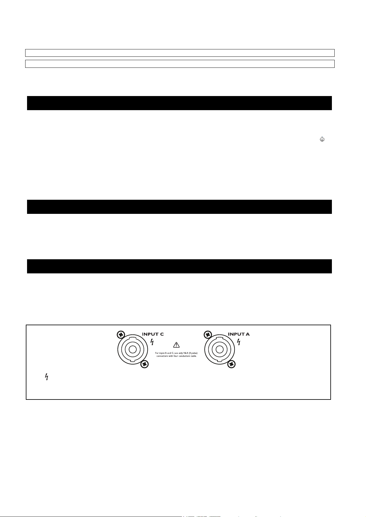
Use only Neutrik NL4 plugs with four cores cables for connecting speakON® connectors.
NEXO-SA cannot be held responsible for damage caused by improper use or modifications to the device, or data that is lost or destroyed.
• Always turn the power off when the device is not in use.
• The performance of components with moving contacts, such as relays and connectors, deteriorates over time. Consult qualified NEXO-SA service personnel about replacing
defective components.
IMPORTANT NOTICE FOR THE UNITED KINGDOM
WARNING: THIS APPARATUS MUST BE EARTHED
IMPORTANT. The wires in this mains lead are colored in accordance with the
following code:
GREEN-AND-YELLOW: EARTH
BLUE : NEUTRAL
BROWN : LIVE
As the colors of the wires in the mains lead of this apparatus may not correspond
with the colored markings identifying the terminals in your plug proceed as follows:
• This applies only to products distributed in the United Kingdom.
COMPLIANCE INFORMATION STATEMENT
1) This device may not cause harmful interference, and
2) This device must accept any interference received including interference that may cause undesired operation. See user manual instructions if interference to
radio reception is suspected.
* This applies only to products distributed in the United States of America.
Connecting the Plug and Cord
The wire which is colored GREEN-and-YELLOW must be connected to the terminal in
the plug which is marked by the letter E or by the safety earth symbol or
colored GREEN or GREEN-and-YELLOW.
The wire which is colored BLUE must be connected to the terminal which is marked
with the letter N or colored BLACK.
The wire which is colored BROWN must be connected to the terminal which is
marked with the letter L or colored RED.
(DECLARATION OF CONFORMITY PROCEDURE)
EUROPEAN MODELS
Purchaser/User Information specifi ed in EN55103-1 and EN55103-2.
Inrush Current: 16 A
Conforms to Environments: E1, E2, E3 and E4.
This mark indicates a dangerous electrically live terminal. When connecting an external wire to this terminal, it is necessary either to
have “a person who have received appropriate guidance on handling” make the connection or to use leads or a cord that have been
manufactured in such way that the connection can be made simply and without problem.
Page 5
Quick Start
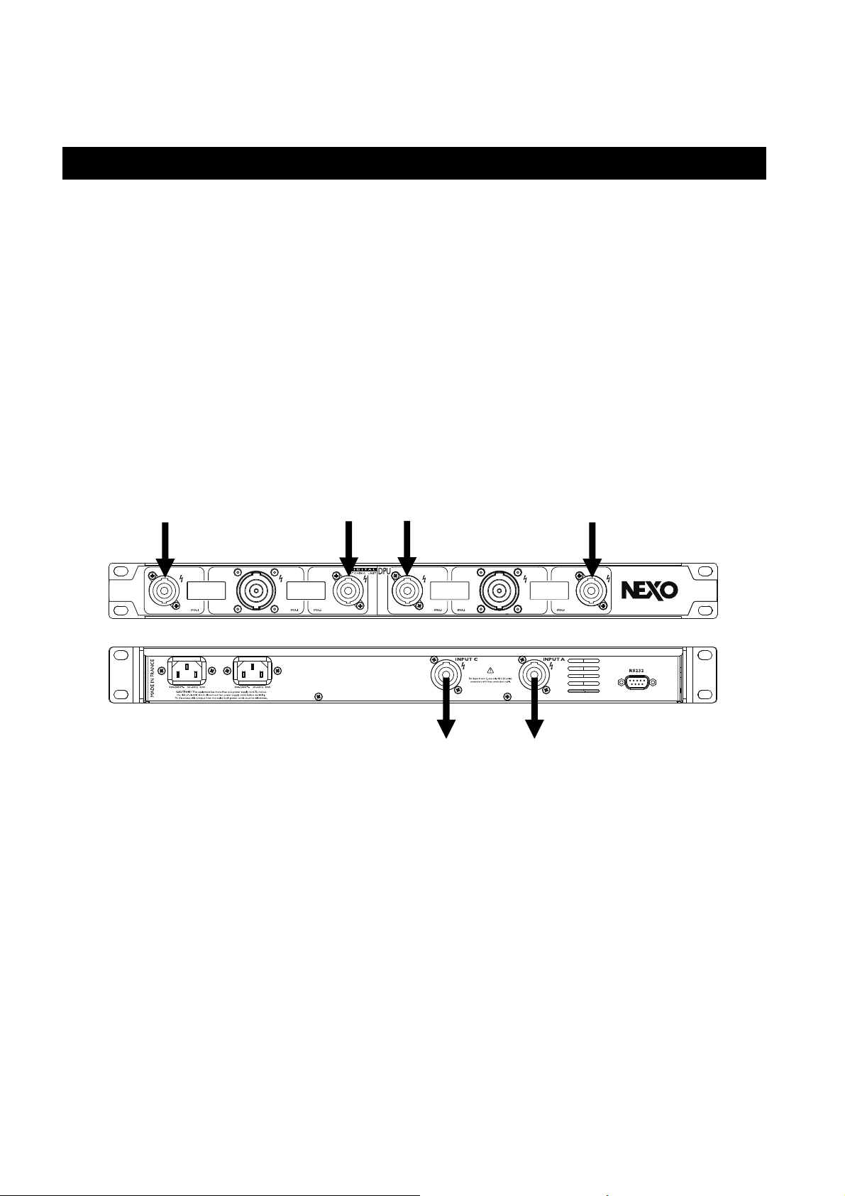
This section will allow you to use quickly the basic functions of this product. This device is intended to set up automatically
the power outputs of an NXAMP Powered TDcontroller to the correct pins on speakON® 4 and speakON® 8 connectors.
However please devote some attention to reading the user manual. A better understanding of specific
features of the DPU digital patching unit will help you to operate your system to its full potential.
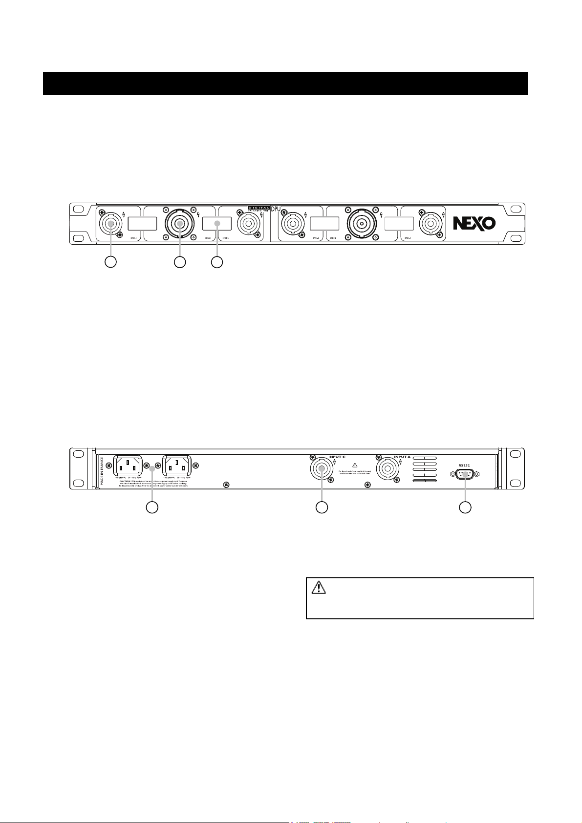
Front panel description
1
1) SpeakON
®
4 poles output
3 2
There are four connectors like this on the front panel.
These connectors will be used to connect any Nexo
speaker that uses the same type of connector.
2) SpeakON
®
8 poles output
There are four connectors like this on the front panel.
These connectors will be used to connect the Nexo
speaker of your choice, if it uses the same type of
connector of it is uses EP6 connector (requiring then
external pin to pin adaptor from speakON® 8 pins 1 to 6
to Amphenol EP6 pins 1 to 6).
Back panel description
1) Mains connectors
There is two mains connectors on the DPU. These two
connectors lead to two fully redundant power supplies
for redundancy purpose, meaning that the DPU can still
work even if one main is missing or in the very unlikely
case that a power supplies fails.
Be sure to connect the two mains input to separate
mains circuit to ensure maximum redundancy.
2) SpeakON
These power inputs must be connected to the power
outputs of the NEXO NXAMP4x4 or NXAMP4x1.
®
4 poles input
3) LCD display
There are four LCDs like this one on the DPU. These
LCDs indicate which speaker should be connected on
which output.
• When speakON
®
4 poles connectors should be used,
the LCD next to it will display the name of the
speaker program chosen on the connected NXAMP.
• When speakON
®
8 poles connectors are in use, both
LCDs on each side of the connectors will display the
name of the connected speakers.
2 1 3
• Connect the NXAMP “Speakon A” output to the DPU
“Input A” input.
• Connect the NXAMP “Speakon C” output to the DPU
“Input C” input.
²²²²WARNING: Use 4 x 4 mm² (AWG11) cable
and four poles speakON® to connect NXAMP power
outputs to DPU inputs (2 meters / 16 feet max).
3) RS232 port
Connect this serial port to NXAMP RS232 port using a
shielded crossover cable only (2 meters / 16 feet max)
with female db9 connectors on each side.
Page 6
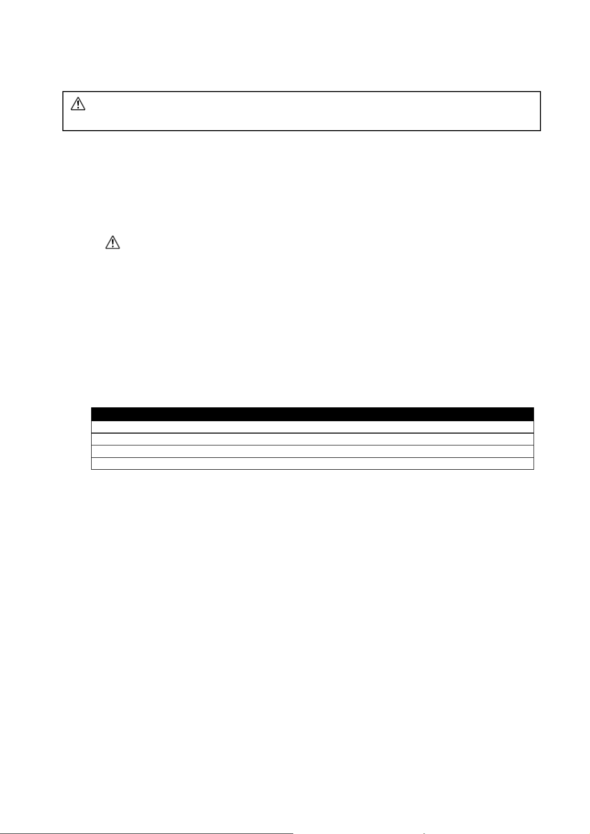
Basic functions
WARNING: NXAMP firmware should be at least revision 3.0 (LOAD3_00) for the DPU to work. If not, the
DPU will stay in stand-by with nothing routed on its outputs.
Connection and start up
NB : A cable kit containing
• 2 x 4 poles 4 x 4mm² speakON
®
cable
• 1 x db9 crossover (null-modem) cable
• 2 x IEC mains cable with lockable connector (available with EU or US plugs).
can be purchased from NEXO separately.
1111 Be sure that the host NXAMP and the DPU are both disconnected from mains.
2222 Connect the two speakON® cables between NXAMP (Speakon A and C) and DPU (Input A and C), and connect
the serial port using a crossover cable (see serial port cabling bellow).
3333 Then connect at least one IEC cable to one of the IEC mains inlet of the DPU. The left most display should lit and
the message “Stand-by’” should appear on the screen.
4
4 Connect the NXAMP mains plug(s) and turn the NXAMP “ON”. Check the LOAD revision while booting up ; it
44
should be LOAD3_10 or above.
5
5 After a few second the current selected speakers on the NXAMP are routed inside the DPU and their names are
55
displayed on the DPU screen.
Crossover (null-modem) serial port cable pin-out
NXAMP serial port pins DPU serial port pins
2 (RXD) NXAMP Receive (DPU Transmit) 3 (TXD)
3 (TXD) NXAMP Transmit (DPU Receive) 2 (RXD)
5 (GND) Signal ground 5 (GND)
Other Unused Other
Page 7
Redundancy using DPU and NXANP
Introduction
Power amplifier redundancy can be achieved using DPU and LOAD3 GPIO mode 6 and 7. DPU is used as a power switch,
able to route the audio power signal from the backup amplifier to the correct speakers when a normal amplifier has failed.
The maximum ratio of backup and normal amplifiers is 1:5. Each DPU communicate with normal NXAMPs through RS232
serial port.
GPIO informs the backup amplifier if a normal amplifier has failed and whether or not the backup amplifier is free. The
backup amplifier recalls a “scene” or “user preset” that contains a copy of all the parameters and preset of the failed
amplifier. One “scene” or “user preset” has to be created for every normal amplifier in a redundant system, and saved in
the backup amplifier’s memory space from 00 to 04.
DPU is used in reverse within a redundancy system. Meaning that power signals from normal NXAMPs are connected to the
front DPU’s connectors and outputted to the speakers using the DPU’s back connectors.
Power Input
Backup Power Input
GPIO cables are not delivered by NEXO. If you wish to set up a redundant power amplifier system, you can make
your own GPIO cable using standard DB25 MAL PLUG KIT. Please follow the instructions below for signals and power
cabling.
The audio signal will be restored about 3 sec. after a normal amplifier failure.
Power Output
Page 8
GPIO mode 6 for backup NXAMPs
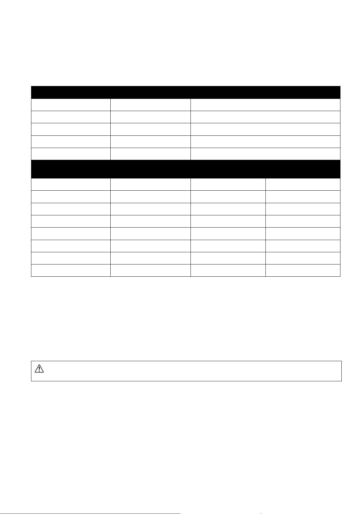
Mode 6 is used for redundancy in fix or live installations using NXAMP and DPU. The GPIO mode 6 is dedicated for
backup amplifiers. Use NXAMP menu: 5.GPIO Mode=> Edit => GPIO ...
Pin Name In/Out On each Impulse (From 1 to 0)
GPInput 1 In Recall Scene 00
GPInput 2 In Recall Scene 01
GPInput 3 In Recall Scene 02
GPInput 4 In Recall Scene 03
GPInput 5 In Recall Scene 04
Pin Name In/Out Meaning when set to 0 Meaning when set to 1
GPOutput 1 Out Backup Nxamp free Backup NXAMP in use
GPOutput 2 Out TBD
GPOutput 3 Out TBD
GPOutput 4 Out TBD
GPOutput 5 Out TBD
GPOutput 6 Out TBD TBD
GPOutput 7 Out TBD TBD
GPOutput 8 Out TBD TBD
When an impulse is detected on GPInput1, Usersetup 00 is recalled.
When an impulse is detected on GPInput2, Usersetup 01 is recalled.
When an impulse is detected on GPInput3, Usersetup 02 is recalled.
When an impulse is detected on GPInput4, Usersetup 03 is recalled.
When an impulse is detected on GPInput5, Usersetup 04 is recalled.
(5volts)
TBD
TBD
TBD
TBD
WARNING: Any setup can be recalled, regardless the loudspeaker family.
GPOutput1 is set to 0 when the backup NXAMP is free, means that no normal NXAMP has failed.
GPOutput1 is set to 1 when the backup NXAMP is used to replace a failed amplifier.
The GPOutput2 to GPOutput8 are not used in GPIO mode 6.
Page 9
GPIO mode 7 for Normal NXAMPs
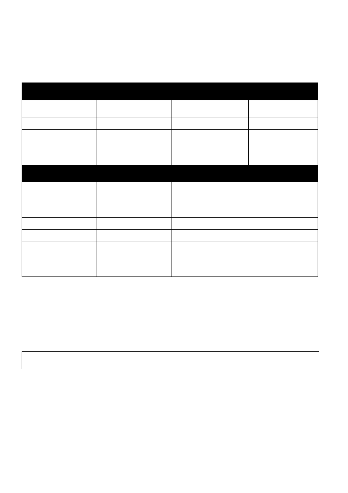
Mode 7 is used for power amplifier redundancy in fix or live installations using NXAMP and DPU. The GPIO mode 7 is
dedicated for normal amplifiers. Use the NXAMP menu: 5.GPIO Mode=> Edit => GPIO …
Pin Name In/Out Meaning when set to 0 Meaning when set to 1
GPInput 1 In Backup NXAMP is free
GPInput 2 In TBD TBD
GPInput 3 In TBD TBD
GPInput 4 In TBD TBD
GPInput 5 In TBD TBD
Pin Name In/Out Each Impulse (From 1
GPOutput 1 Out NXAMP Failed NXAMP running OK
GPOutput 2 Out TBD TBD
GPOutput 3 Out TBD TBD
GPOutput 4 Out TBD TBD
GPOutput 5 Out TBD TBD
GPOutput 6 Out TBD TBD
possible to switch DPU
to 0)
impossible to switch DPU
Meaning when set to 1
(5volts)
Backup NXAMP is used
(5volts)
GPOutput 7 Out TBD TBD
GPOutput 8 Out TBD TBD
When signal on GPInput1 is 0, no amplifier has failed and the backup amplifier is still free and ready to take over.
When signal on GPInput1 is 1, one or more amplifiers have failed, all DPUs that are connected to the backup amplifier are
frozen. (One DPU has already switched)
When the NXAMP is operational the GPOutput1 is set to 1.
When a problem is detected on NXAMP the GPOutput1 is set to 0.
WARNING: Do not mix scene’s numbers and backup amplifier’s GPInput numbers that are connected to your normal
amplifiers GPOutput1. Wrong connections will lead to wrong scenes recalls in the backup amplifier.
The GPOutput2 to GPOutput8 and GPInput2 to GPInput5 are not used in GPIO mode 7.
Page 10
1+1-2+2-3+3-4+
4-
S1
NL8MD
1+1-2+
2-
S2
NL4
1+1-2+
2-
S3
NL4
SPK8-1
SPK4-1
SPK4-2
1+1-2+2-3+3-4+
4-
S4
NL8MD
1+1-2+
2-
S5
NL4
1+1-2+
2-
S6
NL4
SPK8-2
SPK4-3
SPK4-4
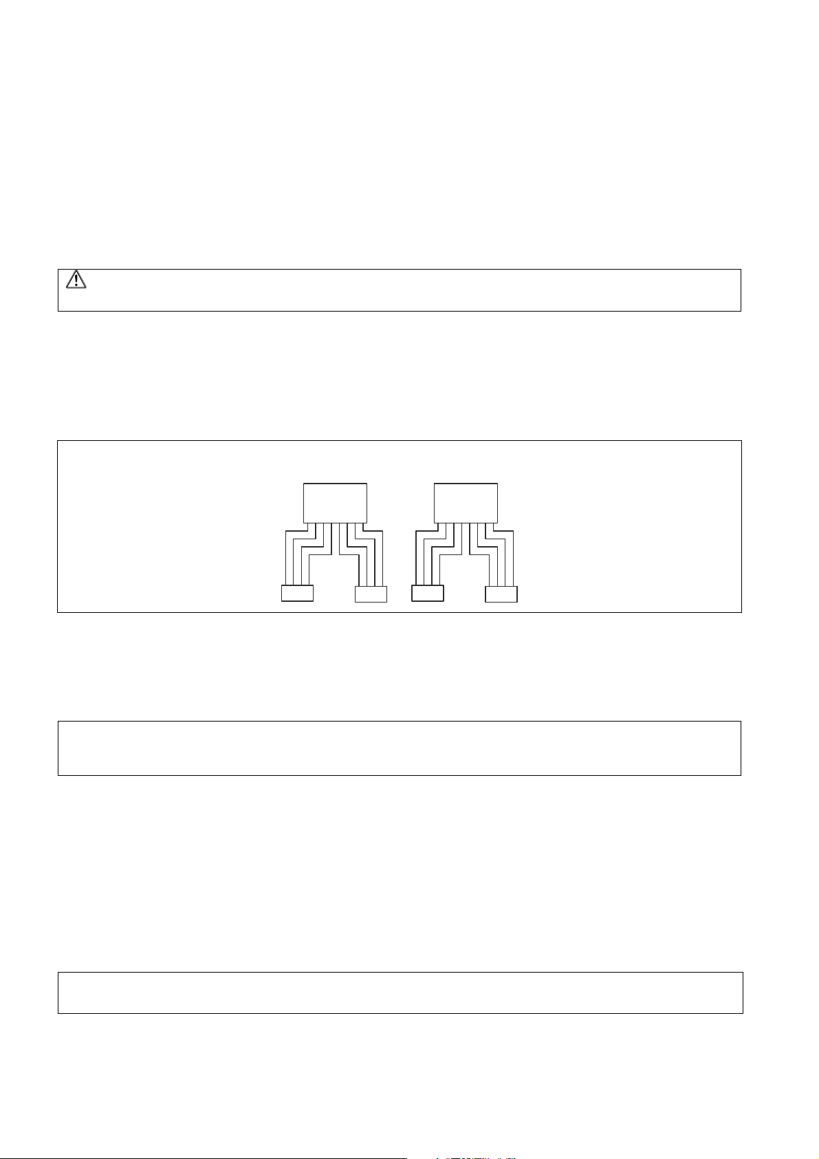
How do I cable NXAMPs and DPU using GPIO MODE 6&7?
1. First you have to define the ratio of normal and backup amplifier, for example 1:5, meaning you have one
backup amplifier for five normal amplifiers.
2. Connect the GPOutput1 of each normal amplifier to the corresponding Backup NXAMP GPInput from 1 to 5.
Connect all the GPInput1 of each normal amplifier to the GPOutput1 of the backup amplifier. Connect GND pins
together to every amplifier.
WARNING: Be sure that each normal amplifier’s GPOutput is connected to the correct Backup NXAMP GPInput,
wrong connection will lead to wrong scenes recalls in the backup amplifier.
3. Then connect Speakons from each Normal NXAMPs A and C outputs to DPU’s SP4-2 and SP4-1 front connectors.
Then connect the Backup NXAMP A and C output to the first DPU’s SP4-4 and SP4-3 front connectors. Then link
DPU together using speakon8 and speakon4. Use Spekon8 connectors to link the backup power from the first
DPU’s SP8-2 connector to second DPU’s SP8-2 connector. If you get more than two normal amplifiers, then link
the second DPU’s SP4-3 and the SP4-4 front connectors to the third DPU’s SP4-3 and SP4-4 front connectors.
And continue to do so to the fifth DPU.
INFO: Linking DPU is possible because all SP4-1 and SP4-2 points are paralleled with the SP8-1 connectors and all
SP4-3 and SP4-4 points are paralleled with the SP8-2 connectors.
4. The two connectors used for outputting power from the redundant system to the speakers are named ‘INPUT C’
and ‘INPUTA’ and are located at the back of the DPU. Connect your speakers to the correct DPU, meaning that
the preset used in the DPU’s host NXAMP is dedicated for the connected speakers.
5. Now that GPIO is connected as well as power SPEAKON, connect each DPU’s RS232 port to their host NXAMP’s
one, using “Cross cable” or “Null modem” cables.
IMPORTANT: In normal operation mode ‘INPUT C’ and ‘INPUT A’ DPU’s back connectors are pure copy of the host
NXAMP’s ‘OUTPUT C’ and ‘OUTPUT A’ connectors. When DPU switch from his host amplifier to the backup amplifier
‘INPUT C’ and ‘INPUT A’ become pure copy of the backup NXAMP ‘OUTPUT C’ and ‘OUTPUT A’ connectors.
6. Then connect the mains to all NXAMPs and DPU, using POWERCONs and IEC cables.
7. Power on all the NXAMPs and DPUs.
8. Then, create “scenes” or “user presets” in the back up amplifier that contain a copy of each normal
amplifier parameters and speaker setup. Go to the backup NXAMP menu, 4.Save/Recall=> save; choose the
scenes name, example 00“nxamp1”, 01“nxamp2” …and save. Memory spaces 00 to 04 are dedicated for
redundancy using GPIO MODE 6. When all normal amplifiers parameters are copied and saved in the backup
amplifier put the backup amplifier in GPIO mode 6 and all normal amplifiers in GPIO mode 7. Regarding NXAMP
audio input patch and “user preset”, see page 11.
NOTE: if you save parameters somewhere else than in memory space 00 to 04, the backup amplifiers won’t be able to
recall your backup scenes when needed.
Page 11
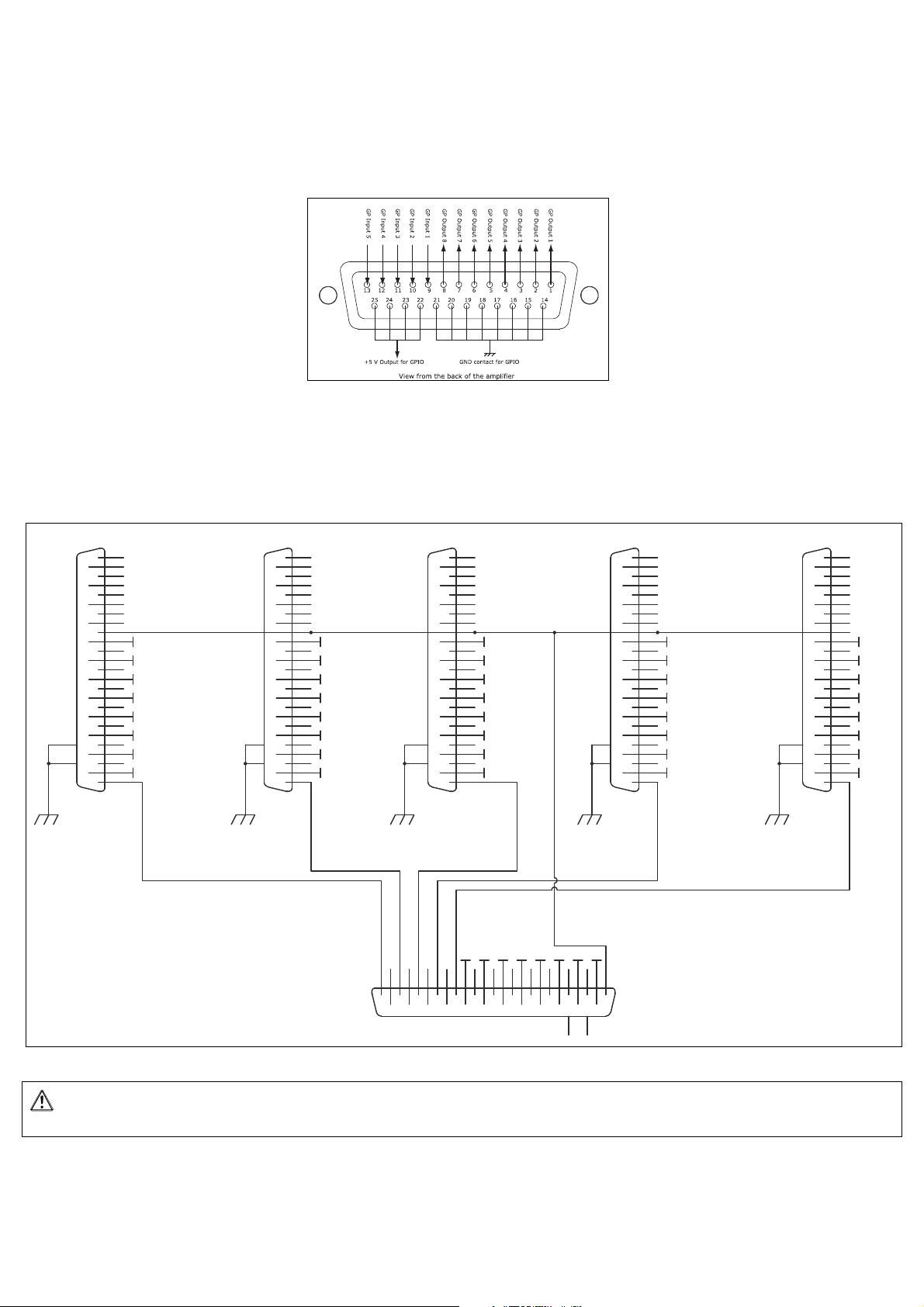
GPIO NXAMP pins description and cabling in a redundant system
1
20
2
21
3
22
4
23
5
24
6
25
7
8
9
10
11
12
13
14
15
16
17
18
19
27
26
D Connec<=>r 25
1202213224235246257
8
9
10
11
12
13
14
15
16
17
18
19
27
26
J6
D Connec<=>r 25
1
20
2
21
3
22
4
23
5
24
6
25
7
8
9
10
11
12
13
14
15
16
17
18
19
27
26
D Connec<=>r 25
1
20
2
21
3
22
4
23
5
24
6
25
7
8
9
10
11
12
13
14
15
16
17
18
19
27
26
D Connec<=>r 25
1
20
2
21
3
22
4
23
5
24
6
25
7
8
9
10
11
12
13
14
15
16
17
18
19
27
26
D Connec<=>r 25
1
20
2
21
3
22
4
23
5
24
6
25
7
8
9
10
11
12
13
14
15
16
17
18
19
27
26
D Connec<=>r 25
GND
GND
GND
GND
GND
GND
GND
GND
GND
GND
GND
GND
GND
GND
GND
GND
GND
GND
GND
GND
GND
GND
GND
GND
GND
GND
GND
GND
GND
GND
GND
GND
GND
GND
GND
GND
GND
GND
GND
GND
GNDGNDGNDGNDGNDGNDGNDGND
NORMAL NXAMP N°1
NORMAL NXAMP N°2
NORMAL NXAMP N°3NORMAL NXAMP N°4NORMAL NXAMP N°5
BACKUP NXAMP
GPOutput1 <=> GPInput5
GPOutput1 <=> GPInput1
GPOutput1 <=> GPInput2
GPOutput1 <=> GPInput3
GPOutput1 <=> GPInput4
All GPInput1 <=> GPOutput1
Find the NXAMP GPIO port pins description below. Special cabling of the GPIOs port is needed to run redundant GPIO
mode 6 & 7 properly.
The maxim ratio when using the redundant GPIO mode 6 and 7 is 1:5, means one backup amplifier for 5 normal
amplifiers. The GPIO cabling for this configuration is described below. The five vertical connectors schematized normal
amplifiers GPIO connectors and the horizontal one the backup NXAMP GPIO connector. If you use less than a 1:5
ratio, follow the same cabling pattern for your specific installation and just remove connectors you don’t used from
the following schematic.
WARNING: When cabling GPIO ports between many amplifiers do not forget to parallel all NXAMP’s GND pins. GND pins are
labeled with a “GND net” that means they are all connected together. Connect a minimum of five GND pins when using a ratio of 1:5.
Page 12
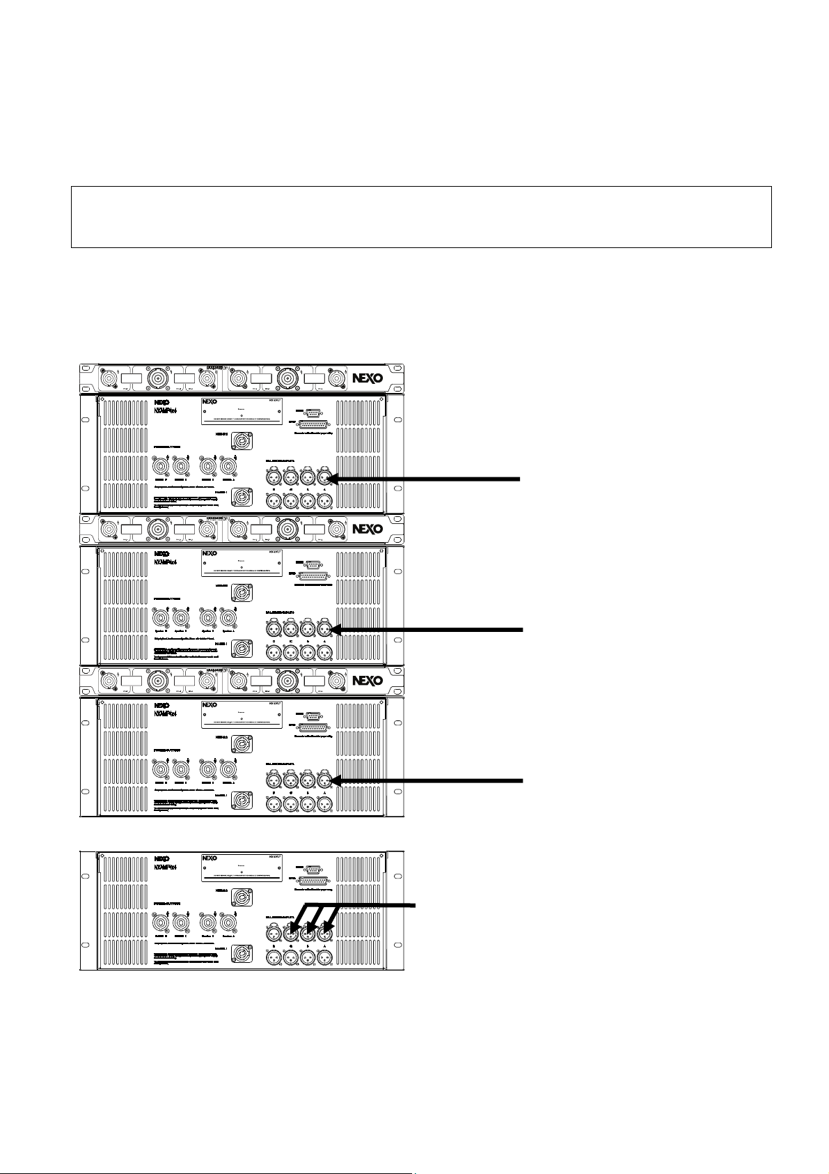
Audio Input Signal cabling in a redundant system
Regarding audio input signals, NXAMP has four analog and four digital inputs, that can be patch independently on each of the
four power outputs. The patch will also be saved within the scene parameters in the backup amplifier and recall when needed.
Note: You can use a maximum of four different audio signals per backup amplifier. If you need more audio signals inputs, add
backup amplifiers.
For example, for a three NXAMP redundant system, you could use three different analog audio signals connected to each
normal amplifiers input A and linked to the backup amplifier analog inputs A, B and C. When saving the normal amplifiers
parameters in the backup amplifier ‘user memory’ space, be careful especially for the audio signal patching. Normal
amplifiers input patch won’t always be the same than the one saved in the backup amplifier “user preset” or
“scenes”.
You could do exactly the same connections using EtherSound digitals audio inputs E, F, G and H.
Analog audio Signal 1
connected to the third
normal amp input A
Analog audio Signal 2
connected to the second
normal amp input A
Analog audio Signal 3
connected to the first
normal amp input A
Analog audio Signals 1 to 3 connected to input C to A.
Scene 00 recall when NXAMP1 failed=> input patch C
Scene 01 recall when NXAMP2 failed => input patch B
Scene 02 recall when NXAMP3 failed => input patch A
Page 13
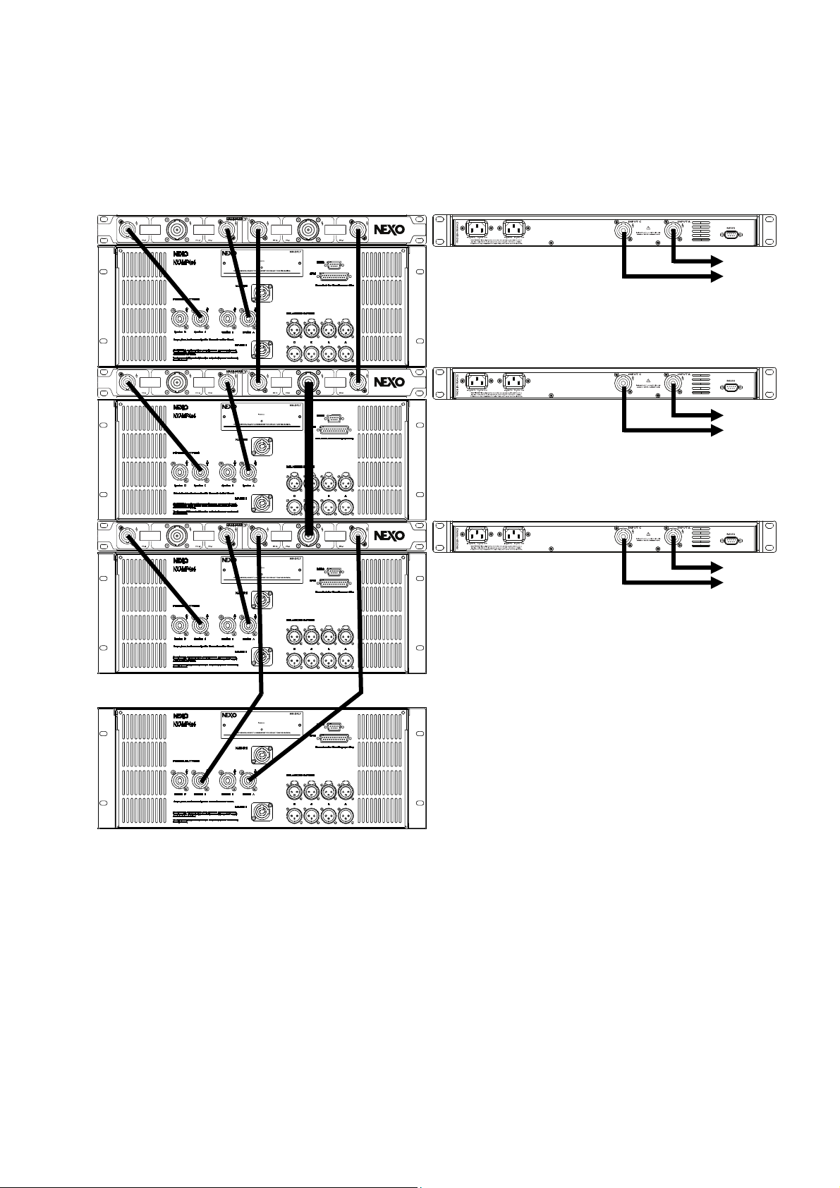
Power cabling between NXAMP and DPU in a redundant system
Use 4 poles Speakons cables and 8 poles Speakons cables if you use more than 1:1 ratio (backup : normal). Reproduce
the same cabling pattern if you use more than three normal amplifiers.
Back side of the rack
Front side of the rack
To Speakers
To Speakers
To Speakers
Page 14
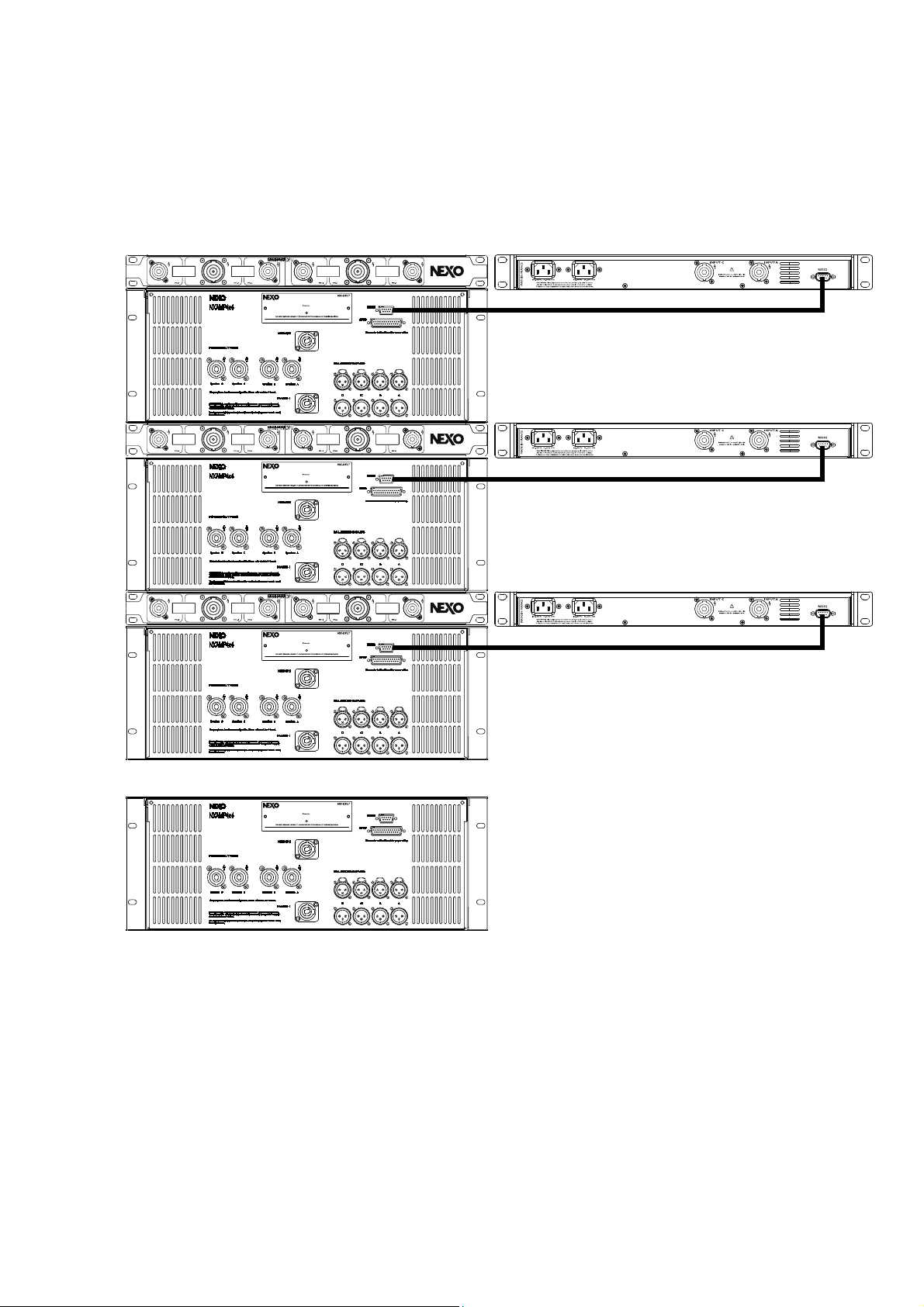
Serial ports cabling between DPU and NXAMP in a redundant system
DB9 null modem or cross cables are used to connect the DPU to their host NXAMP using RS232 connectors. The serial link is use to pilot the DPU
when needed.
Back side of the rack Front side of the rack
Page 15
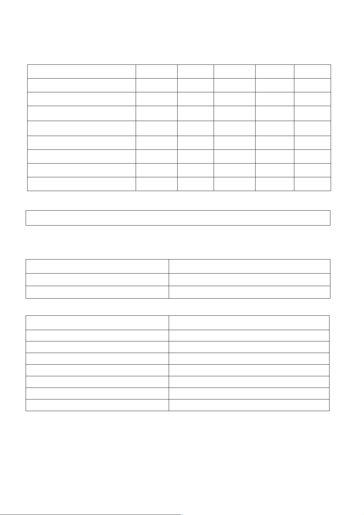
What’s needed for redundancy?
Parts 1:1 ratio 1:2 ratio 1:3 ratio 1:4 ratio 1:5 ratio
NXAMP 4X4 or 4X1 2 3 4 5 6
DPU 1 2 3 4 5
SP4 power cables 0.5m 4 6 10 12 16
SP8 power cables 0.5m 0 1 1 2 2
DB9 Null modem 1m 1 2 3 4 5
IEC main cable for DPU 2 4 6 8 10
PowerCon main cable for NXAMP 2 6 8 10 12
DB25 plugs MAL for GPIO 2 3 4 5 6
INFO: Some cable kits are available for DPU. (1*DB9 NULL modem cable, 2*Speakons four poles 1m, and 2*lockable IEC mains power cords
1.5m (US or EU))
Ordering References
Accessories REFERENCE
Accessories REFERENCESSSS DESCRIPTION
Accessories REFERENCEAccessories REFERENCE
DPT-CKITC Cable Kit for DPU 220V
DPT-CKITU Cable Kit for DPU 110V
Accessories REFERENCEs
Accessories REFERENCEs DESCRIPTION
Accessories REFERENCEsAccessories REFERENCEs
NX.ES104
NX.ES104 Optional NXAMP EtherSound card
NX.ES104NX.ES104
NX.DT 104
NX.DT 104 Optional NXAMP DANTE card
NX.DT 104NX.DT104
NX.DP U
NX.DP U Digita l Patchi ng Unit ‘DPU’
NX.DP UNX.DP U
NXAMP4 X1U
NXAMP4 X1U Powered Digital TD Controller 4x1U.
NXAMP4 X1UNXAMP4 X1U
NXAMP4 X1C
NXAMP4 X1C Powered Dig ital TD Controller 4x1C.
NXAMP4 X1CNXA MP4X1C
NXAMP4 X4U
NXAMP4 X4U Powered Digital TD Controller 4x4U.
NXAMP4 X4UNXAMP4 X4U
NXAMP4 X4C
NXAMP4 X4C Powered Dig ital TD Controller 4x4C.
NXAMP4 X4CNXA MP4X4C
DESCRIPTION
DESCRIPTIONDESCRIPTION
DESCRIPTION
DESCRIPTIONDESCRIPTION
Optional NXAMP EtherSound card
Optional NXAMP EtherSound cardOptional NXAMP EtherSound card
Optional NXAMP DANTE card
Optional NXAMP DANTE cardOptional NXAMP DANTE card
Digita l Patchi ng Unit ‘DPU’
Digita l Patchi ng Unit ‘DPU’Digita l Patchi ng Unit ‘DPU’
Powered Digital TD Controller 4x1U. 110
Powered Digital TD Controller 4x1U. Powered Digital TD Controller 4x1U.
Powered Digital TD Controller 4x1C. 220
Powered Digital TD Controller 4x1C. Powered Digi tal TD Controll er 4x1C.
Powered Digital TD Controller 4x4U. 110
Powered Digital TD Controller 4x4U. Powered Digital TD Controller 4x4U.
Powered Digital TD Controller 4x4C. 220
Powered Digital TD Controller 4x4C. Powered Digi tal TD Controll er 4x4C.
110V
110110
220V
220220
110V
110110
220V
220220
V
V V
V
V V
V
V V
V
V V
Page 16
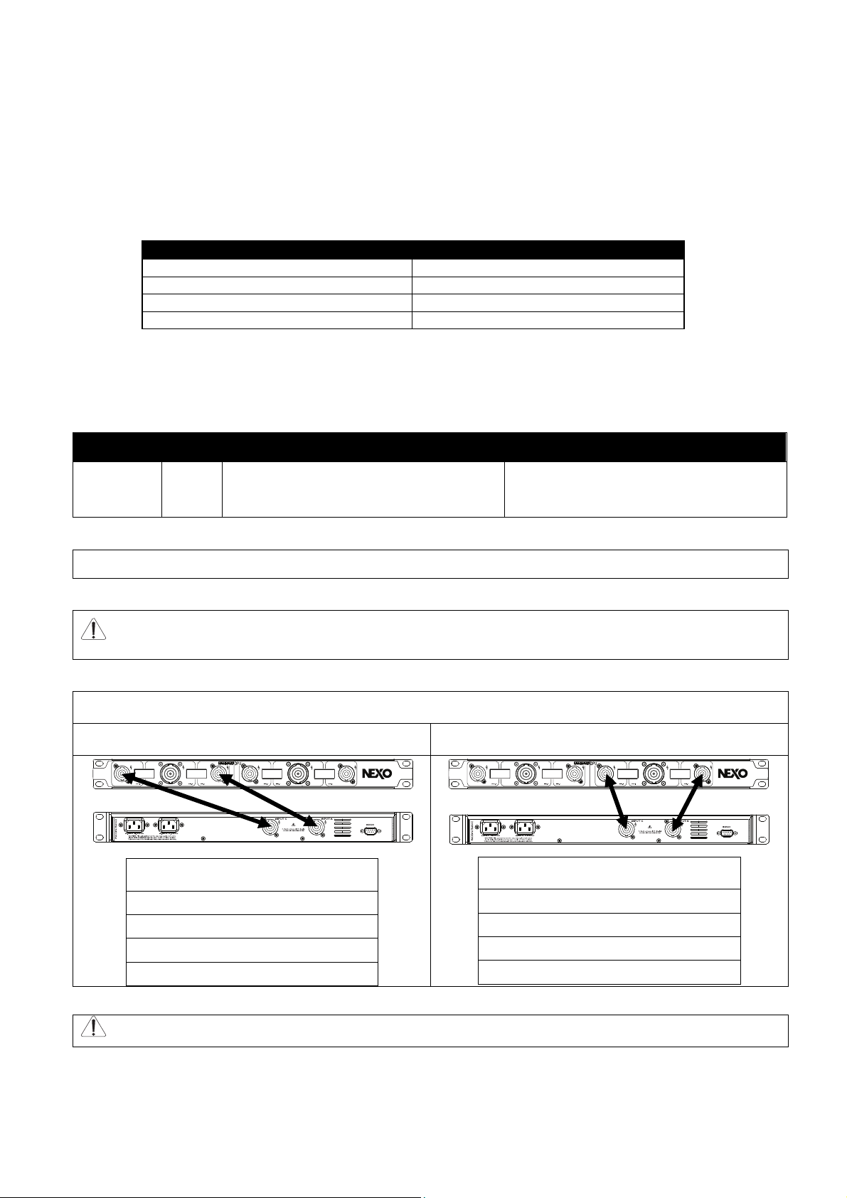
Redundancy using DPU without NXAMP
A specific firmware has been developed for the DPU to be use with any amplifiers that possess a GPIO port. Uploading
this new firmware into the DPU through the internal JTAG plug will convert the DPU’s RS232 serial port to a GPIO port.
To load the firmware use a SILICON LABORATORIES ADAPTATEUR USB DEBUG for C8051FXX: DEBUGADPTR1-USB.
DPU GPIO MODE (RS232 connector pin description)
This new GPIO port can be drive by any amplifier that provides a 5volts GPIO signal. The DPU will switch the power when
the voltage on pin 2 is 0V. Do not forget to connect the ground (Pin5), between the DPU and the backup
amplifier.
Pin Name In/Out Pin 2 is set high (5volts) Pin 2 from 1 (5Volts) to 0
5.5V supply 30mA MAX Pin 3 (TXD)
GPIO In (0V-5V) Pin 2 (RXD)
Signal ground Pin 5 (GND)
Unused Others
Pin 2 (RXD)
In
‘INPUT C’ and ‘INPUT A’ back DPU’s
connectors are respectively connected to
SP4-1 and SP4-2 connectors
‘INPUT C’ and ‘INPUT A’ back DPU’s
connectors are respectively connected to
SP4-3 and SP4-4 connectors
NOTE: When using the DPU with the GPIO firmware the ratio of normal amplifier and backup amplifier is 1:1.
WARNING: Over voltage on pin 2 may damage your DPU, please be sure that your GPIO output does not exceed 20V
Internal connections in DPU (schematized by double arrow)
Normal operation Mode Pin 2 = 5V Backup operation Mode Pin 2 = 0V
Connection between SP4-1 and INPUTC connectors. (Same
between SP4-2 and INPUTA connectors.)
SP4-1 (1+) connected to INPUTC (1+)
SP4-1 (1-) connected to INPUTC (1-)
SP4-1 (2+) connected to INPUTC (2+)
SP4-1 (2-) connected to INPUTC (2-)
Connection between SP4-3 and INPUTC connectors. (Same
between SP4-4 and INPUTA connectors).
SP4-3 (1+) connected to INPUTC (1+)
SP4-3 (1-) connected to INPUTC (1-)
SP4-3 (2+) connected to INPUTC (2+)
SP4-3 (2-) connected to INPUTC (2-)
WARNING: Do not exceed 10KW on DPU’s power connectors.
Both normal and backup amplifiers have to be fed with same audio signals (four different audio signals maximum) and
run same speakers presets.
 Loading...