

Page 1

ALPHA SERIES
Alpha M3 & M8
Alpha Em & EF
B1-18 & B1-15
S2 Sub-bass
User Manual
Page 2

PAGE 2/37
INTRODUCTION
ALPHA SERIES USER MANUAL V1.0
DATE: 14/01/00 18:27
INTRODUCTION 3
ALPHA SERIES DESCRIPTION 3
LOUDSPEAKERS 3
NEXO TDCONTROLLERS 4
THE X-BOW FLYING SYSTEM 4
GENERAL SET-UP INSTRUCTIONS 5
SPEAKER WIRING 5
FLYING THE SYSTEM 6
TDCONTROLLERS S ETTI N GS 9
INITIAL SET-UP PRECAUTIONS 10
ALPHA ARRAYS - SOME BASIC RULES 11
ALPHA S2 PLACEMENT 11
SPL VERSUS FREQUENCY 11
SPL VERSUS DISTANCE 11
DIRECTIVI TY - COV ERAGE 14
AMPLIFIERS 16
POWER 16
CURRENT RATING 16
AMPLIFIER G AIN S 16
GAIN VALUE 17
ADVANCED PROTECTIONS 17
PASSIVE CROSSOVER FUSES 18
TECHNICAL SPECIFICATIONS 19
ALPHA S2 19
ALPHA B1-15 / B1- 18 20
ALPHA M3 / M8 21
ALPHA EM / EF 22
DIRECTIVI TY TABLES 23
CURVES 24
ALPHA S2 24
ALPHA B1-18 24
ALPHA B1-15 24
ALPHA M3 25
ALPHA M8 28
ALPHA EM 31
ALPHA EF 31
DIMENSIONS 34
TRANSPORT 35
CONNECTION DIAGRAMS 36
Page 3

PAGE 3/37
INTRODUCTION
ALPHA SERIES USER MANUAL V1.0
DATE: 14/01/00 18:27
INTRODUCTION
Thank you for selecting NEXO Alpha Series. This manual is intended to provide you with
necessary and useful information about your Alpha System:
• S2
• B1-15, B1-18
• M3, M8
• EM, EF
Please devote some attention to reading this manual. A better understanding of some specific
features of the Alpha Series will help you to operate your system to its full potential.
This manual is intended to be com prehensive, and we hope that it will satisfy your requirements.
Should you require further information, please contact your NEXO agent.
Alpha Series description
Loudspeakers
The Alpha range includes the following speakers:
• The S2 Sub-bass is a double 18-inch r esonator loaded sub-bass, dedicated to very low
frequency reproduction (< 80 Hz).
• The B1-15 & B1-18 are com plex loaded (bass-reflex & exponential horn) bass cabinets;
the B1-15 houses one 15-inch driver, while the B1-18 houses one 18-inch driver;
frequency response ranges from 40 Hz up to 200 Hz.
• The Mid-high M3 & M8 are concentric horn cabinets dedicated to the 200 Hz - 20 kHz
frequency range reproduction; the MF range is handled by two exponential horn loaded
10-inch drivers whose response is optimised by two Nexo designed phase plugs; the HF
range is handled by one constant dire ctivity horn loaded two-inch Neodymium driver. M3
coverage is 35° (H) x 35°(V), M8 75° (H) x45° (V).
• The Mid-high EM forms par t of the re cently introduced Alpha E Series; its size and power-
rating is smaller than that of the Alpha M3 & M8; the mid range is handled by an
exponential horn loaded 10’’ driver, while the HF range is handled by a constant directivity
horn loaded ceramic 2’’ driver. Alpha EM coverage is 75°x30°.
• The compact EF is dedicated to the full audio range reproduction 40 Hz – 20 kHz; it
consists of one EM and one B1-18 stacked in a monoblock compact format.
Alpha cabinet formats are designed for optimal array assembly (see section “D
IMENSIONS” p.34); all
the cabinets have the same width and depth; height is in multiples of 200 mm UNITS.
• Six UNITS (1200 mm): Alpha S2, Alpha EF.
• Four UNITS (800 mm): Alpha B1-18.
Page 4

PAGE 4/37
ALPHA SERIES DESCRIPTION
ALPHA SERIES USER MANUAL V1.0
DATE: 14/01/00 18:27
• Three UNITS (600 mm): Alpha B1-15, Alpha M3, Alpha M8.
• Two UNITS (400 mm): Alpha EM.
Nexo TDcontrollers
The Alpha Series speakers are associated with the NX241 Digital TDcontroller, which can be
configured to provide compr ehensive control of the above, mentioned cabinets. For a complete
description of this unit please ref er to the "NX241 User Manual". You may also use one of the
following analogue TDcontrollers that preceded the NX 241. Pleas e ref er to the c orr es ponding user
manual or contact your NEXO agent for more information on these products.
• Sub TDcontroller for use with Alpha S2;
• Alpha TDcontroller for use with Alpha B1-15, B1-18, M3 & M8;
• AlphaE TDcontroller for use with Alpha B1-18, EM & EF;
This manual will only refer to the NX241 T Dcontroller. Please remember that the NX241 Digital
TDcontroller is a software-based product for which regular updates will be published. Please
consult the NEXO web site for the latest software releases.
The X-BOW flying system
The design of the X-BOW flying system has been optimised for the dispersion specifications of the
Alpha range, its mechanical characteristics match accurately the acoustical properties of the
speakers.
The concept of this flying system enables eff icient array assembly, with minimum space between
cabinets, thus reducing edge diffraction.
The X-BOW flying system includes four main components, references are:
• ALXBOW: main chassis (1);
• ALXKIT: hinge (1) and cable links (2);
• ALXBRIDLE: D-ring (1) and leg chains (3);
• ALXCASE: flight-case for a complete X-BOW flying kit (capacity: 4 X-BOWs).
Page 5
PAGE 5/37
GENERAL SET-UP INSTRUCTIONS
ALPHA SERIES USER MANUAL V1.0
DATE: 14/01/00 18:27
General Set-up Instructions
Speaker Wiring
Connectors
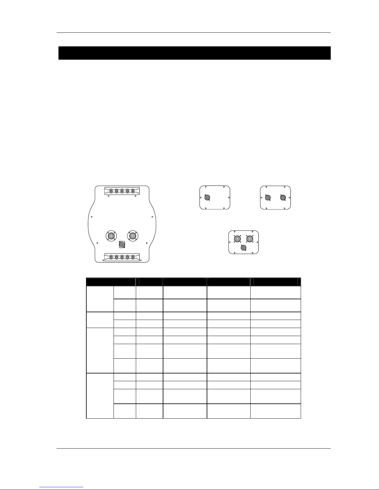
The loudspeakers are c onnected via SPEAKON c onnectors , NL4FC and NL8FC (not s upplied). A
wiring diagram is pr inted on the c onnec tion panel located on the bac k of each cabinet. The pins of
the SPEAKON sockets are identified in/out and connected in parallel within the enclosures. A
single 8-conductor cable carries all four bands required by the Alpha M3/B1/S2 system and the
cabinet connectors allow all three types of cabinet to be saf ely linked at the loudspeaker end. (See
Connections Diagrams at the end of this manual).
NB: The Alpha S2 back panel features only one 4- pin SPEAKON connector in order to prevent
accidental parallel connection: very few amplifiers are able to drive such low impedance loads at
the required power level.
CONNECTOR
S2 B1-15 / B1-18 M3 / M8 EM / EF
1±
In / Out
VLF
To VLF (S2) To VLF (S2) To VLF (S2)
SP4
#1
2±
Not
connected
In / Out LF (B1) To LF (B1) To LF (B1)
1±
- To VLF (S2) - -
SP4
#2
2±
- In / Out LF (B1) -
1±
- - In VLF (S2) In / Out VLF (S2)
2±
- - In / Out LF (B1) In / Out LF (B1)
3±
- - In / Out MF
P: In / Out MF+HF
A: In / Out MF
SP8
#1
4±
- - In / Out HF
P: Not connected
A: In / Out HF
1±
- - In VLF (S2) In VLF (S2)
2±
- - In / Out LF (B1) In / Out LF (B1)
3±
- - In / Out MF
P: In / Out MF+HF
A: In / Out MF
SP8
#2
4±
- - In / Out HF
P: Not connected
A: In / Out HF
P = MF-HF passive / A = MF- HF a ctive
S2
B1/15
B1/18
M3
M8
EM
EF
Page 6
PAGE 6/37
GENERAL SET-UP INSTRUCTIONS
ALPHA SERIES USER MANUAL V1.0
DATE: 14/01/00 18:27
Cables
Nexo recommends the exclusive use of multi-conductor cables to connect the system: the cable kit
is compatible with all the cabinets, and there is no possible confusion between VLF, LF, MF and
HF sections.
Cable choice consists mainly of selecting the correct cable section (s ize) in relation to the load
resistance and the c able length. Too small a c able section will increase its serial resis tance; this
would induce power-loss and response variations (damping factor).
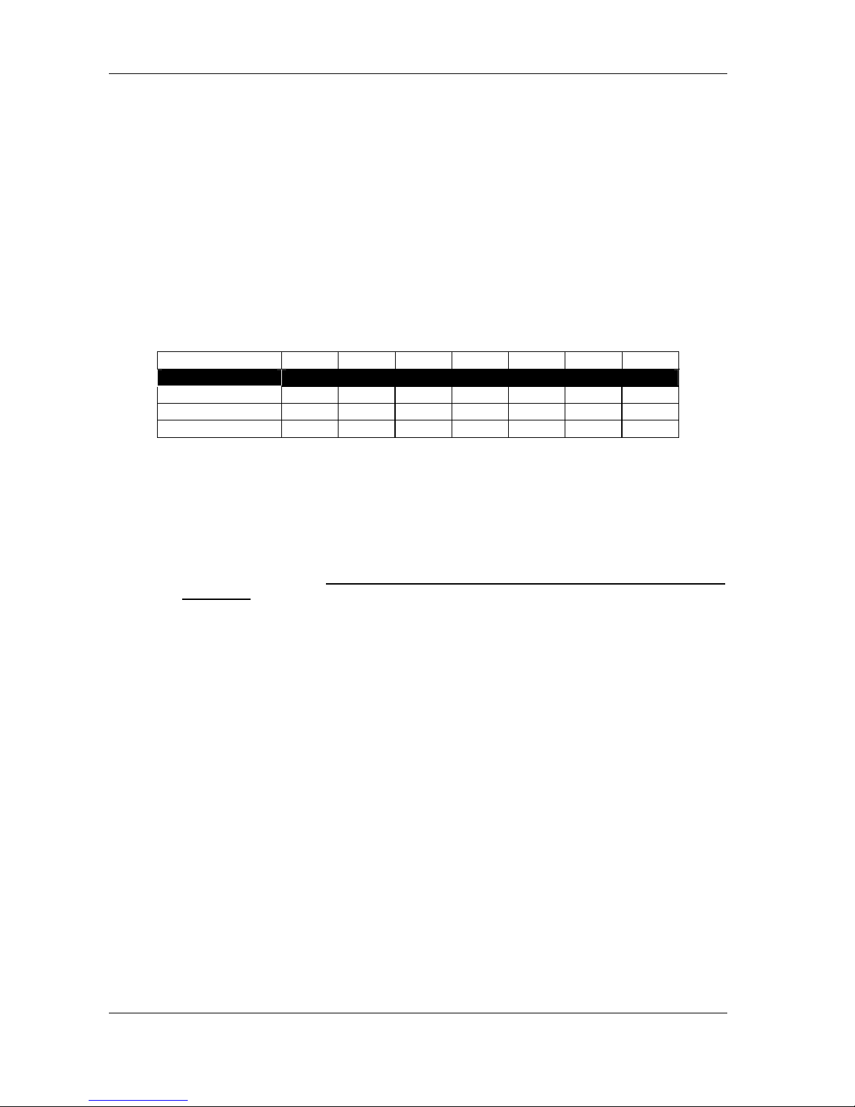
For a serial resistance less or equal to 4% of the load impedance (damping factor = 25), the
maximum cable length is given by:
L
max
= Z x S S in mm2, Z in Ohm, L
max
in meters
The table below indicates these values, for 3 common sizes.
Load Impedance (Ω) 2 3 4 6 8 12 16
Cable section Maximum Length (meters)
1,5 mm² (AWG #14) 3 4.5 6 9 12 18 24
2,5 mm² (AWG #12) 5 7.5 10 15 20 30 40
4 mm² (AWG #10) 8 12 16 24 32 48 64
IMPORTANT NOTE: Long speaker cables induce capacitive effects that impair the quality of audio
signals. If long speaker cables must be used, ensure that they do not remain coiled while in use.
Flying the System
Alpha Series loudspeakers are equipped with steel anchor plates that can be fitted with NEXO XBOW flying accessories. The X-BOW Flying Manual must be thoroughly read before flying
the system.
The following points are designed to remind the user of safe practice when flying the X-BOW
system. They cannot address every possible circumstance in which the system might be deployed;
therefore the user must always apply his or her k nowledge, experience and comm on sense. If in
any doubt, seek advice from your NEXO agent.
Flown Systems Safety
• Always inspect all the X-BOW components and cabinet Fly Rails for damage before
assembly. Pay special attention to the lifting points, trom bone sock ets and safety clips. If
you suspect that any of the components are damaged or defec tive, DO NOT USE THE
AFFECTED PARTS. Contact your supplier for replacements.
• Read the X-BOW Flying manual carefully. Also, be familiar with the manuals and safe
working procedures for any ancillary equipment which will be used with the X-BOW
system such as hoists, steel wires and other rigging components.
• Ensure that all local and National regulations regarding the saf ety and operation of flying
equipment are understood and adhered to. Information on these regulations can usually
be obtained from Local Government Offices.
• When deploying the X -BOW system always wear protective headwear, footwear and eye
protection.
Page 7

PAGE 7/37
GENERAL SET-UP INSTRUCTIONS
ALPHA SERIES USER MANUAL V1.0
DATE: 14/01/00 18:27
• Do not allow inexperienced persons to handle X-BOW flying systems. Installation
personnel should be trained in loudspeaker flying techniques and should be fully
conversant with this manual.
• Ensure that motor hoists, hoist control systems and ancillary rigging components are
currently certified as safe and that they pass a visual inspection prior to use.
• Ensure that public and personnel are not allowed to pass beneath the system dur ing the
installation process. The work area should be isolated from public access.
• Never leave the system unattended during the installation process.
• Do not place any object, no m atter how small or light, on top of the system during the
installation procedure. The object m ay fall when the system is f lown and is likely to cause
injury.
• Secondary safety steels must be installed once the system has been flown to the
operating height. Secondary steels must be fitted irres pec tive of the loc al saf ety standards
applicable to the territory.
• Do not fly the system over areas to which the audience has access.
• Ensure that the system is secure and prevented from pivoting about the motor hoist. Avoid
any form of dynamic loading to the assembly.
• NEVER attach any item to the X-BOW other than the NEXO X-BOW accessories.
• When flying outdoor systems ensure that the system is not exposed to wind or snow loads
and is protected from rainfall.
• The X-BOW requires regular inspec tion and testing by a competent test centre. NEXO
recommend that the s ystem is load tes ted and cer tif ied annually or more frequently if local
regulations require.
• When de- rigging the system ensure that the sam e duty of care is given to the procedur e
as for the installation. Pack X-BOW components carefully to prevent damage in transit.
• Correct training is fundamental to safe practise when working with loudspeakers flying
systems. NEXO recom mend that us ers contac t local industry associations f or inform ation
on specialist course. Information for UK and International training agencies can be
obtained by contacting:
• The Production Services Association (PSA),
School Passage,
Kingston-upon-Thames,
KT1 SDU Surrey,
ENGLAND
Telephone: +44 (0) 181 392 0180
Ground Stack Safety
Statistically, many more injuries occur due to unstable ground stacked PA systems than those
associated with flown systems. There are s everal reasons for this fact, however the m essage is
clear:
Page 8

PAGE 8/37
GENERAL SET-UP INSTRUCTIONS
ALPHA SERIES USER MANUAL V1.0
DATE: 14/01/00 18:27
• Always survey the supporting structure upon which a ground stack is to be built. Always
look beneath PA wings to inspect the deck suppor t and if necessary ask for the stage
scrims and dressings be removed to allow access.
• X-BOW components should be used to stabilise ground stacks and to ensure that
cabinets remain securely registered to eac h other. The X- HINGE can be used to connect
Alpha cabinets both vertically and horizontally at the rear and horizontally at the front
edge. In addition the Fly Track can be used as a connection point f or a safety wire to a
secondary structure.
• If the stage surface slopes, as it does in some theatres, ensure that the system is
prevented from sliding forwards due to vibration. This may require the fitting of timber
battens to the stage floor.
• For outdoor systems ensure that that the system is protected from wind forces which
might cause the ground stac k to become unstable. W ind forc es can be huge, especially
upon large systems, and should never be underestimated. Observe meteorological
forecasts, calculate the lik ely effect upon the system prior to erection and ensure that the
system is secured appropriately.
• Take care when stacking cabinets. Always employ safe lifting procedures and never
attempt to build stacks without sufficient personnel and equipment.
• Never allow anyone, whether operators, artists or mem bers of the public to clim b onto a
ground stacked PA system. Anyone who needs to climb over 2m high should be fitted with
suitable safely equipment including a clip-on harness. Please refer to local Health and
Safety legislation in your territory. Your dealer can help with advice on access to this
information.
• Apply the same attention to all safety matters when de-stacking systems.
• Be aware that safety procedures are as important in the truc k and in the warehouse as
they are at the venue.
Page 9

PAGE 9/37
GENERAL SET-UP INSTRUCTIONS
ALPHA SERIES USER MANUAL V1.0
DATE: 14/01/00 18:27
TDcontrollers settings
The Alpha Series c abinets will not perf orm c orrectly without their associated T Dcontrollers . Sound
quality and reliability are totally dependent on the correct use of the TDcontrollers, in association
with the Nexo instructions, provided.
All manuals & associated technic al notes must be r ead before set-up. Please contact your NEXO
agent for any literature inquiry.
NX241 Digital TDcontroller
The digital NEXO NX241 controller is able to drive the entire current Nexo range (PS & Alpha
series). The following set-ups are supported (at the time of publication).
Alpha Series
ALPHATD B1+M3
Configure Input A to drive a 3-Way Alpha System.
ALPHATD S2+B1+M3
SubTD S2-63Hz
Configure Input A to drive a 4-Way Alpha System.
ALPHATD S2+B1+M3
SubTD S2-80Hz
Configure Input A to drive a 4-Way Alpha System.
ALPHATD S2+B1+M3
S2-63Hz AUX inB
Configures Input B (right) to drive the SUB channel independently.
ALPHATD S2+B1+M3
S2-80Hz AUX inB
Configures Input B (right) to drive the SUB channel independently.
Alpha E Series
AlphaE STEREO
Configures 2 passive Alpha EM + 2 B1-18 (or 2 Alpha EF) in stereo.
AlphaE MONO
Configures Input A to drive 1 passive Alpha EM + B1-18 + S2 sub
cabinet. (Channel 4 is unused).
Very important:
Due to the DSP processing time, analogue Sub TDcontroller / Alpha TDcontroller /
AlphaE TDcontroller are incompatible with the Digital NX241and should never be
used in conjunction to control cabinets within the same array.
Page 10

PAGE 10/37
GENERAL SET-UP INSTRUCTIONS
ALPHA SERIES USER MANUAL V1.0
DATE: 14/01/00 18:27
Initial Set-up Precautions
When running up a system particularly one which includes brand new cabinets for the first time the
power should be increased slowly to approximately 50% and the system operated at this level f or
two hours. During the following two hours of operation the power level should be limited to
approximately 75%. This procedure allows the adhesives and suspensions within the loudspeaker
components to stabilise and will extend their working life.
In all cases, it is advisable to connec t the loudspeakers only after all the other com ponents have
been wired and are operating correctly. This is particularly important for the amplifiers and the
TDcontroller. It is a good practice to turn down all the amplifier gains before connecting the
cabinets and then turn them up again individually with a medium level music sourc e fed into the
system. The sens e LEDs of the corresponding TDcontroller channel should light up accordingly.
This will help to locate cabling errors, par ticularly channel line inversions, which would disable the
TDcontroller protections and may invalidate the warranty.
IMPORTANT
If more than one amplifier is being driven from an output of the NX241 controller only those
amplifiers which are not connec ted
to sense inputs may be attenuated. If the sensed amplifier is
attenuated and the slave amplifiers are not severe system damage will result!
Page 11

PAGE 11/37
ALPHA ARRAYS - SOME BAS IC RULES
ALPHA SERIES USER MANUAL V1.0
DATE: 14/01/00 18:27
Alpha Arrays - Some Basic Rules
The concept of arraying speakers derives from two requirements:
• Increased sound pressure level;
• Extended coverage area.
Array behaviour is very complex, and a bad design can lead to very poor results. The Alpha
system was designed to be flexible, allowing the user to optimise the design for a dedicated
situation; its development included a long m eas urem ent progr am on a very large variety of arrays.
Below are some simple rules that the user should respect.
Alpha S2 Placement
The nominal ef ficiency data for Alpha S2 is given for when positioned on the floor (half-s pace).
When flown the acoustic output on axis will be 3 dB lower and if positioned in a corner the acoustic
output on axis will increase by 3 dB.
SPL Versus Frequency
Array frequency response is strongly related to wavelength and array architecture.
• At low frequencies, wavelength being very large in relation to the size of the cabinets,
speakers set close to eac h other will always radiate in phase. The gain in sound pressure
level LGSPL will be of 6 dB per doubling, i.e. if n Alpha S2 or B1 are installed:
LGSPL(20Hz-100Hz) = 20 log10(n)
• In the mid frequency range, the gain depends on the configuration of the array, and will
range from 3 to 6 dB per doubling, i.e. for n Alpha M3, M8, EM or EF:
10 log10(n)
≤ LGSPL(100Hz-1kHz) ≤ 20 log10(n)
• At high frequencies, wavelength being short in relation to the size of the cabinet, the gain
level is smaller : no gain will be obtained for cabinets angled at their nominal cover age,
maximum gain will be obtained for n cabinets pointing in the same direction. Therefore,
the gain will range from 0 to 3 dB per doubling; for n Alpha M3, M8, EM or EF:
0
≤ LGSPL(1kHz-10kHz) ≤ 10 log10(n)
SPL Versus Distance
In open-air conditions, the level of sound at a given distance is related to the following parameters:
• The size and the geometry of the source, which determ ines the shape of the sound wave
(spherical, cylindrical, plane);
• Hygrometry and temperature: viscos ity of the air and ther mal conduction cause an energy
loss increasing with frequency. This phenomenon is referred to as excess attenuation.
Page 12
PAGE 12/37
ALPHA ARRAYS - SOME BAS IC RULES
ALPHA SERIES USER MANUAL V1.0
DATE: 14/01/00 18:27
Single Cabinet
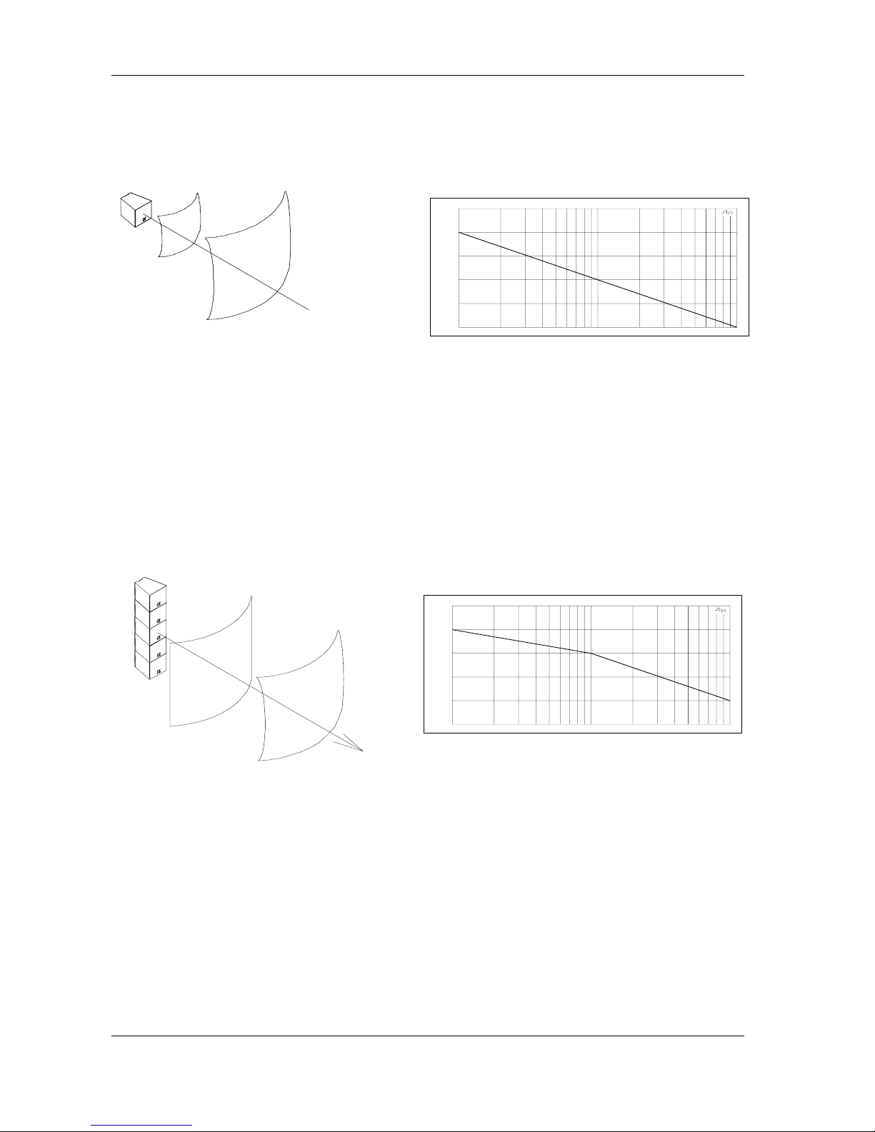
Lp(1m) being the sound pressure level at 1m, the level at a distance d (in meters) is given by:
Lp(d) = Lp(1m) - 20 log
10
(d)
• Single Cabinet SPL versus Distance
For example, if the level measured at 1 meter is Lp(1m) = 100 dBSPL, the level at 2 meters will be
94 dBSPL, 80 dBSPL at 10 meters and s o on. Note that under these conditions of sm all source
and open air, the sound pressure level will be decreasing by 6 dB when doubling the distance.
Straight Vertical Array (long throw)
Some open-air applic ations m ight require loud level on a wide f requency range at a long distance.
It is then recommended to stack a large number of Alpha M3/M8/EM vertically. Up to a determined
distance - function of the frequency and the height of the stack -, the sound wave is cylindrical
(3dB/2d); it becomes progressively spherical (6dB/2d) above that distance.
• Transition from cylindrical to spherical wave front
1 10 100
60.000
70.000
80.000
90.000
100.00
110.00
Sound Pressure Level (dBSPL) / distance (meters)
1 10 100
60.000
70.000
80.000
90.000
100.00
110.00
Sound Pressure Level (dBSPL) / distance (meters)
Page 13

PAGE 13/37
ALPHA ARRAYS - SOME BAS IC RULES
ALPHA SERIES USER MANUAL V1.0
DATE: 14/01/00 18:27
Hygrometry and Temperature - Air Absorption
Under usual conditions, air absorption increas es when relative humidity decreases and increas es
when temperature decreases.
Air absorption gives a linear attenuation, i.e. a constant value of loss of dB per meter: if 1 dB is lost
from 10 to 20 meters, 2 dB will be lost from 20 to 40 meters, 4 dB from 40 to 80 meters and so on...
The tables below list these values for normalised frequencies, and various values of relative
humidity and temperature:
At 20°C:
[dB] loss / meter Up to 1 kHz 2 kHz 4 kHz 8 kHz 16 kHz
RH 20% 0 0.02 0.06 0.20 0.66
RH 50% 0 0.01 0.03 0.08 0.27
RH 80% 0 0.00 0.02 0.05 0.17
Air absorption over a 50m distance; RH=20%-50%-80%
At RH 50%:
[dB] loss / meter Up to 1 kHz 2 kHz 4 kHz 8 kHz 16 kHz
10°C 0 0.01 0.04 0.13 0.43
20°C 0 0.01 0.03 0.08 0.27
30°C 0 0.01 0.02 0.06 0.19
20 100 1k 10k 20k
FREQ(Hz)
-40.00
-30.00
-20.00
-10.00
0.0
10.000
LEVEL(dBV)
AUDIO PRECISION vs 17 JUL 97 19:30:05
Air absorption over a 50m distance; t=10°C-20°C-30°C
The speed of sound C varies with temperature according to the formula below:
273 t20 C +°=
Where t° is the temperature in °C
The delay time between two sources spaced at a distance d is then:
∆t = C/d
20 100 1k 10k 20k
-40.00
-30.00
-20.00
-10.00
0.0
10.000
Frequency (Hz) / Attenuation (dB)
Page 14

PAGE 14/37
ALPHA ARRAYS - SOME BAS IC RULES
ALPHA SERIES USER MANUAL V1.0
DATE: 14/01/00 18:27
Directivity - Coverage
The two main qualities one might expect from a cabinet for array constructions are:
• A good directivity control in the mid and high frequency region, which guarantees the
steadiness of the interference region where dips and lobes occur;
• A strong roll-of f of the directivity function at the -6dB cut- off angle, which minimises the
size of the interference region.
The Alpha series cabinets were designed to res pect these two criteria. Particular ly, the Alpha M3
features a cons tant c overage angle +/- 5° from as low as 800 Hz up to 12 kHz, with high values of
dB loss / degrees at cut-off angle.
Directivity of Multiple Sources - What HAPPENS?
In order to understand the coverage behaviour of combined s ources, wavelength m ust be related
to the space between sources.
The wavelength
λ (in meters) of o sine wave is determined by:
λ = C/f where f is the frequency of the sine wave
This gi v es :
λ(20Hz) = 17 m, λ(100Hz) = 3.4 m, λ(1kHz) = 34 cm and λ(20kHz) = 1.7 cm
Interference
The distance between sources generates a path
length difference between the two signals that is nil
on axis and increas es with the listening angle. If this
path length difference increases to half the
wavelength in a specific direction, the two signals
will cancel in that direction. This phenomenon is
often described as « interference ».
Resulting directivity
At low frequencies -because wavelength is much larger than the spacing between sourcesinterference is generally not significant. However the directivity index will increase.
In the mid and high frequency range, where wavelength is comparable to spacing between
sources, the directivity polar plots will show dips and lobes. The amplitude of these lobes will
depend on the directivity of the individual sources and on their angulations.
Small Arrays (less than 4 Alphas M3 / M8)
The amplitude of the dips and the lobes is minimised when angling the cabinets at their nominal
coverage angle. If the angle is less than the cover age, the interferenc e region will be larger, and if
the angle exceeds that value, there will be a « hole » between the cabinets.
It is therefore strongly recommended when using a small amount of cabinets to angle them at their
nominal coverage angle (Alpha M3: 35°x35°, M8: 75° x 45°; EM/EF: 75° x 30°).
Path length
difference
Page 15

PAGE 15/37
ALPHA ARRAYS - SOME BAS IC RULES
ALPHA SERIES USER MANUAL V1.0
DATE: 14/01/00 18:27
The only situations where such arrays can be assembled with very little angle are long throw
applications (very small ver tical coverage) because the interf erences are less significant at lar ge
distances from the array.
Large Arrays (4 Alphas M3 / M8 and above)
Construction of large arrays derives from im portant SPL requirements rather than lar ge listening
angles: although the Alpha M3 is a high Q cabinet, 4 boxes ar e enough to cover a 140° horizontal
plane. Therefore, large arr ays will usually assemble cabinets at less than their nominal coverage
angle.
Measurements and s imulations show that when using a large amount of cabinets, the individual
behaviour of a cabinet will determine the roll-off on the limits of the coverage zone, and the
architecture of the array will be responsible for the behaviour in the coverage zone.
For examples of s uitable cabinet configurations please refer to the Alpha System Flying Manual
and to subsequent technical notes.
Page 16

PAGE 16/37
AMPLIFIERS
ALPHA SERIES USER MANUAL V1.0
DATE: 14/01/00 18:27
Amplifiers
Power
NEXO recomm ends high power amplifiers in all cases. Budget constr aints are the only reason to
select lower power amplifiers. If an incident occurs on an installation without protection the fact that
amplifiers only generating half their rated output power ( -3dB) ar e used will not change anything in
respect of possible dam age. This is due to the fact that the RMS power handling of the weakest
component in the system is always 6 to 10 dB lower than the amplifier rating.
Current rating
It is very important that the amplifier behaves correctly under low load conditions. A speaker
system is reactive by nature, on transient signals like music it will require much higher
instantaneous current than its nominal impedance would indicate (four to ten times more).
Amplifiers are gener ally specified by continuous RMS power into resistive loads however the only
useful inform ation in that respect is the specif ication into a 2-ohm load. It is poss ible to make an
amplifier listening test by loading them with twice the number of cabinets considered for the
application (2 speakers per channel instead of one, 4 instead of 2) and m odulating at high level
(onset of clipping). If the signal does not noticeably deteriorate the amplifier is well adapted
(overheating after approximately ten minutes is normal but thermal protection must not operate too
quickly after starting this test).
Amplifier gains
Technical knowledge on the amplifiers to be used with the system is essential. This data is the key
to the correct alignment of the s ystem. It is especially important to know the gain of all amplifiers
used in your set-up. The tolerance shall be about ±0,5 dB. In practice this can be difficult to achieve
because:
• Some amplifier brands have an identical input sensitivity for models of different power
rating (this infers a different voltage gain for each model). For example a range of
amplifiers with different power outputs having a published input sensitivity of 775mV/0dBm
or 1.55V/+6dBm will have a wide range of actual gains, the higher the power, the greater
the gain.
• Various other brands may offer c onstant gain but only within a given product range for
example they may fit only fixed input sensitivity on their semi-professional amps.
• Even if a manufacturer applies the c onstant gain rule to all m odels , the value selected will
not necessarily be the same as that chosen by other manufacturers.
• Some products can exhibit manufacturing tolerances for the same model of ±1dB or more.
Some amplifiers may have been modified, possibly without any label indicating the new
values and some m ay have gain switches fitted inter nally where it is imposs ible for the
user to verify the actual setting without opening the amplifier cas ing. In cases where you
don't know the gain of your amplifier (or want to check it) please read the following
instructions.
1. Unplug any cabinet from the amp
2. W ith a signal generator feed a sine wave at 1000Hz at a known voltage (say
0.5V) to the input of the amplifier under test.
Page 17
PAGE 17/37
AMPLIFIERS
ALPHA SERIES USER MANUAL V1.0
DATE: 14/01/00 18:27
3. Measure the Voltage at the output of the amplifier.
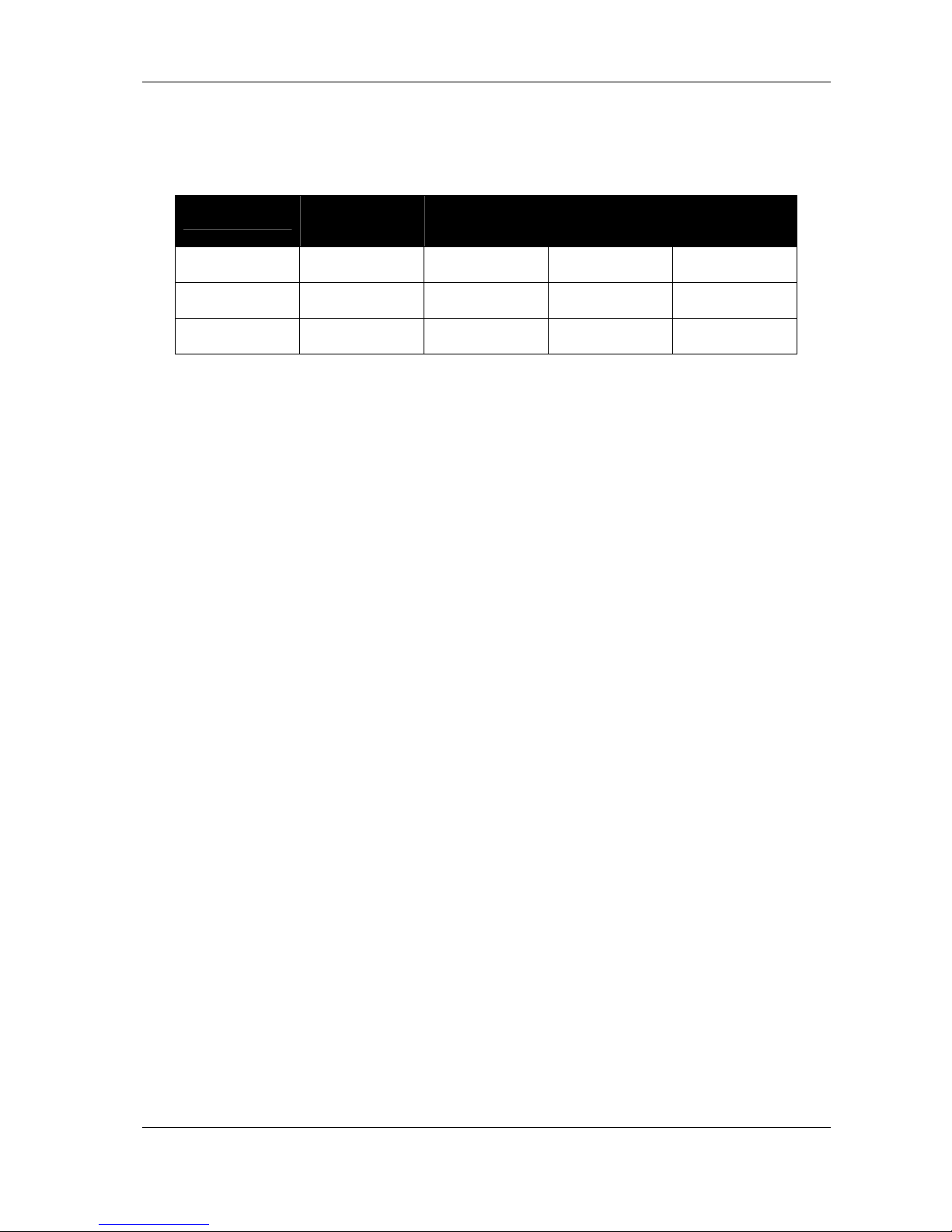
4. Calculate the gain using the formula Gain = 20 * LOG10(Vout/Vin)
Some examples:
Gain
Vin
20dB 26dB 32dB 37dB (1.4V
sensitivity /
1350Wrms)
0.1V 1V 2V 4V 7.1V
0.5V 5V 10V 20V 35.4V
1V 10V 20V 40V 70.8V
Remember that constant sensitivity settings will give a different gain value when the amplifier
power is different.
Gain value
NEXO recommends low gain amplifiers: +26dB is recommended, as it is at the same time
adequately low and quite common am ongst amplifier manufac turers. This gain setting improves
signal to noise ratio and allows all preceding electronic equipment, including the TDcontr oller, to
operate at optimum level. Remember that using a high gain amplifier will propor tionally raise the
noise floor by the same amount.
Advanced protections
Some high-end amplifiers may have some advanced functions similar to those found in the NX241
TDcontroller ("loudspeak er offset integration", "limiter", "compres sor"...). These functions are not
adapted to specific s ystem requirem ents and m ay interfere with the com plex pr otection algorithm s
used in the NX241. NEXO do not advis e using other protection systems in conjunction with the
NX241 and they should be disabled.
Page 18

PAGE 18/37
PASSIVE CROSSOVER FU SES
ALPHA SERIES USER MANUAL V1.0
DATE: 14/01/00 18:27
PASSIVE CROSSOVER FUSES
Please note, within both Alpha & AlphaE cabinet families a fuse is fitted to protect the internal
passive filter network in the event of a voice coil f ailure. This fus e is located on the filter network ,
which is attached to the input panel of the following cabinets.
• Alpha M3/8 cabinets
• Alpha EM series cabinets
• Alpha EF series cabinets
It is vital that this fuse is check ed at regular service intervals and especially when replacing any
loudspeaker components.
If the fuse fails it will not prevent the cabinet f rom f unctioning but, should the c abinets be oper ated
in this condition, the audio quality will be seriously degraded.
Failure to replace a defec tive fus e will cause a dif f erence in audio quality between fully operational
cabinets and those with defective fuses. It is very important to replace the fuse with exactly the
same type and value as the original fitted to the cabinet.
The various fuse specifications are:
• Alpha M3/8 cabinets T1.25A/250V 5X20mm
• Alpha EM/F MF T6.3A/250V 5X20mm
• Alpha EM/F HF T5A/250V 5X20mm
Page 19
PAGE 19/37
TECHNICAL SPECIFICATIONS
ALPHA SERIES USER MANUAL V1.0
DATE: 14/01/00 18:27
TECHNICAL SPECIFICATIONS
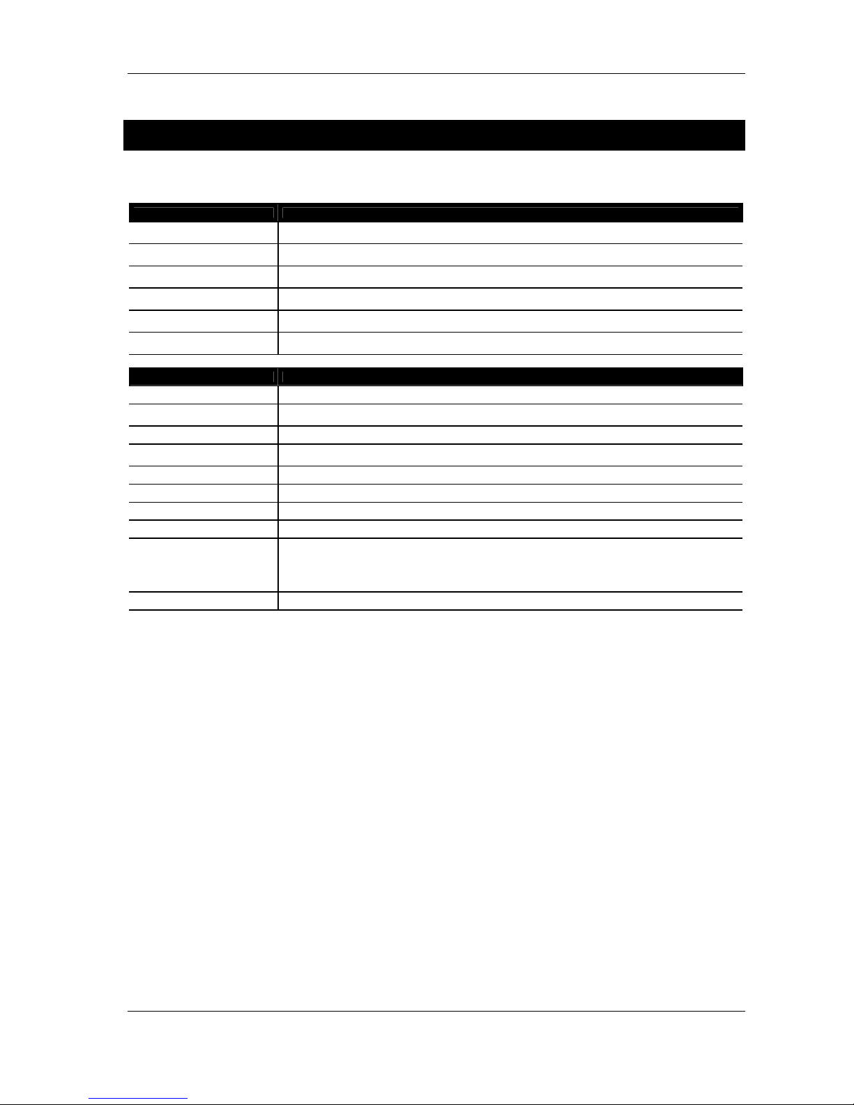
Alpha S2
SYSTEM SPECS ALPHA S2 with Sub TDcontroller
Frequency
Response [a]
32 Hz – 64 Hz ± 3 dB
Usable Range @6dB [a]
29 Hz – 180 Hz
Sensitivity 1W @
1m [b]
105 dB SPL
Peak SPL @ 1m
[b]
140 dB Peak
Nominal
Impedance
3 ohms (2.7 min)
Recommended
Amplifiers
1800 to 2400 Watts into 3 ohms
FEATURES ALPHA S2
Components 2 x 18’’ (46cm) long excursion 6 ohms drivers, high efficiency acoustic load.
Height x Width x
Depth
1200 x 689 x 754 mm carpet version
(47 ¼" x 27 1/8 " x 29 11/16")
Shape 22.5 Trapezoid
Weight: Net
85 kg (187 Lb)
With wheel board: 95 kg (209 Lb)
Connectors 1 x 4 poles Speakon 1+ & 1- (Sub S2)
Construction Baltic Birch with Dark Grey carpeting, Structured Black coating painting finish also available.
Handles 4 Metal Bar Handles
Front Finish Acoustic Foam on hex perforated steel grid (77% transparent)
Flying points
4 Flying Tracks on front (7 positions on 2° steps)
Top to bottom Steel Back plate
2 Flying Tracks on Back (Hinge fixing)
Internal top to bottom Steel links
Painted version without Flying Tracks also available
Fixed Installation The X-BOW Flying Tracks can also receive standard Aircraft Flying Fittings.
As part of a policy of continual improvement, NEXO reserves the right to change specifications without notice.
[a] Response Curves and Data: Anechoic Far Field above 200 Hz, Half-space Anechoic below 200 Hz.
Usable Range Data: Frequency Response Capability with TD crossover slopes removed.
[b] Sensitivity & Peak SPL: will depend on spectral distribution. Measured with band limited Pink Noise.
Refers to the specified +/- 3 dB range. Data are for Speaker + Processor + recommended amplifier combinations.
Page 20
PAGE 20/37
TECHNICAL SPECIFICATIONS
ALPHA SERIES USER MANUAL V1.0
DATE: 14/01/00 18:27
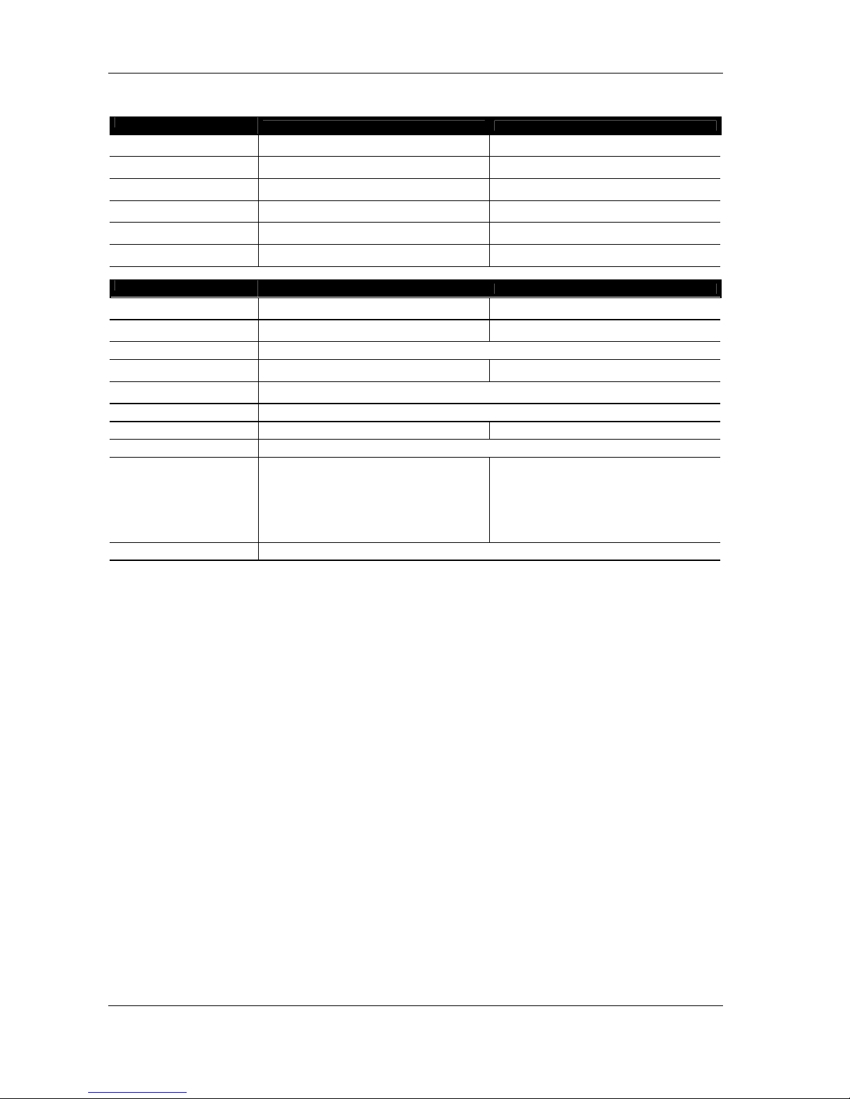
Alpha B1-15 / B1-18
SYSTEM SPECS
ALPHA B1-15 ALPHA B1-18
Frequency
Response [a]
Wideband: 42 Hz – 180 Hz ± 3 dB
Xover: 80 Hz – 190 Hz ± 3 dB
40 Hz – 230 Hz ± 3 dB
Usable Range @6dB [a]
39 Hz – 600 Hz 38 Hz – 600 Hz
Sensitivity 1W @
1m [b]
106 dB SPL 107 dB SPL Nominal
Peak SPL @ 1m
[b]
140 dB Peak 142 dB Peak
Nominal
Impedance
6 ohms (5.2 mini) 6 ohms (4.7 mini)
Recommended
Amplifiers
900 to 1200 Watts into 6 ohms 900 to 1400 Watts into 6 ohms
FEATURES
ALPHA B1-15 ALPHA B1-18
Components 1 x 15" (38 cm) 6 ohms
Folded Horn, Composite Curve
1 x 18" (46 cm) 6 ohms
Folded Horn, Composite Curve
Height x Width x
Depth
600 x 689 x 754 mm
(23 5/8" x 27 1/8 " x 29 11/16")
800 x 689 x 754 mm
(31.49" x 27 1/8 " x 29 11/16")
Shape
22.5° Trapezoid
Weight: Net 51 kg (112 Lb)
With wheel board: 58 kg (128 Lb)
69.9 kg (155 Lb)
With wheel board: 79 kg (175 Lb)
Connectors
2x 4 poles Speakon (In / Out)
1+ & 1- (Sub S2)
2+ & 2- (Bass B1)
Construction
Baltic Birch with Dark Grey carpeting, Structured Black coating painting finish also available.
Handles
2 Metal Bar Handles 4 Metal Bar Handles
Front Finish
Acoustic Foam on hex perforated steel grid (77% transparent)
Flying points
4 Flying Tracks on front (7 positions on
2° steps)
Top to bottom Steel Back plate
4 Flying Tracks on Back (Hinge fixing)
Internal top to bottom Steel links
Painted version without Flying Tracks
also available
Crossbow Flying System cabinet
Hardware:
Optional 4 Flying Tracks on Front
Internal top to bottom Steel links
Optional 2 Flying tracks on back (Hinge
fixing)
Painted version without Flying Tracks
also available
Fixed Installation
The X-BOW Flying Tracks can also receive standard Aircraft Flying Fittings.
As part of a policy of continual improvement, NEXO reserves the right to change specifications without notice.
[a] Response Curves and Data: Anechoic Far Field above 200 Hz, Half-space Anechoic below 200 Hz.
Usable Range Data: Frequency Response Capability with TD crossover slopes removed.
[b] Sensitivity & Peak SPL: will depend on spectral distribution. Measured with band limited Pink Noise.
Refers to the specified +/- 3 dB range. Data are for Speaker + Processor + recommended amplifier combinations.
Page 21
PAGE 21/37
TECHNICAL SPECIFICATIONS
ALPHA SERIES USER MANUAL V1.0
DATE: 14/01/00 18:27
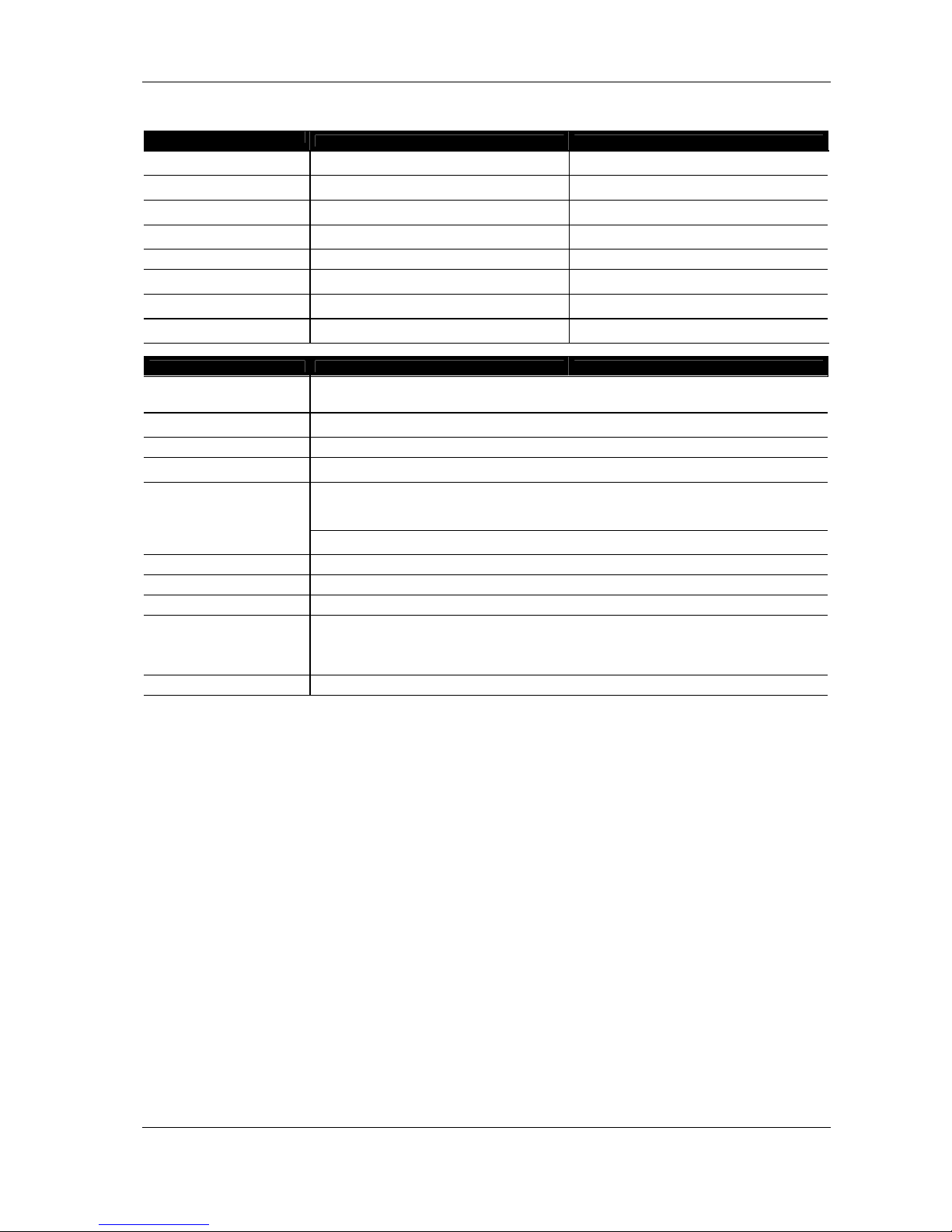
Alpha M3 / M8
SYSTEM SPECS
ALPHA M3 ALPHA M8
Frequency
Response [a]
190 Hz – 19 kHz ± 3 dB 190 Hz – 19 kHz ± 3 dB
Usable Range @6dB [a]
150 Hz – 20 kHz 150 Hz – 20 kHz
Sensitivity 1W @
1m [b]
110 dB SPL 108 dB SPL
Peak SPL @ 1m
[b]
145 dB Peak 143 dB Peak
Dispersion [c]
35° x 35° 75° x 45° (HF Horn Rotatable)
Directivity: Q & DI
[c]
Q = 32 – DI = 15 dB (Nominal f > 630
Hz)
Q = 20 – DI = 13 dB (Nominal f > 630
Hz)
Nominal
Impedance
MF: 12 ohms (15.5 min)
HF: 12 ohms (8.0 min)
MF: 12 ohms (15.5 min)
HF: 12 ohms (8.0 min)
Recommended
Amplifiers
MF: 650 to 900 Watts into 12 ohms
HF: 350 to 500 Watts into 12 ohms
MF: 650 to 900 Watts into 12 ohms
HF: 350 to 500 Watts into 12 ohms
FEATURES ALPHA M3 ALPHA M8
Components
MF: 2 x 10" (24 cm) 8 ohms 3” Coil Drivers; Dual Ring Phase Plugs
HF: 1 x 3’’ Neodynium Driver, Titanium diaphragm
Coaxial mounted wave guide
Height x Width x
Depth
600 x 689 x 754 mm Carpet version
(23 5/8" x 27 1/8 " x 29 11/16")
Shape 22.5° Trapezoid
Weight: Net
57 kg (126 Lb)
With wheel board: 64 kg (141 Lb)
2 x 8 poles Speakon (In / Out)
1+ & 1- (Sub S2)
2+ & 2- (Bass B1)
3+ & 3- (MF)
4+ & 4- (HF)
Connectors
1 x 4 poles Speakon (to B1 & S2)
1+ & 1- (Sub S2)
2+ & 2- (Bass B1)
Construction Baltic Birch with Dark Grey carpeting, Structured Black coating painting finish also available.
Handles 2 Metal Bar Handles
Front Finish Acoustic Foam on hex perforated steel grid (77% transparent)
Flying points
4 Flying Tracks on front (7 positions on 2° steps)
Top to bottom Steel Back plate
4 Flying Tracks on Back (Hinge fixing)
Internal top to bottom Steel links
Painted version without Flying Tracks also available
Fixed Installation The X-BOW Flying Tracks can also receive standard Aircraft Flying Fittings.
As part of a policy of continual improvement, NEXO reserves the right to change specifications without notice.
[a] Response Curves and Data: Anechoic Far Field above 200 Hz, Half-space Anechoic below 200 Hz.
Usable Range Data: Frequency Response Capability with TD crossover slopes removed.
[b] Sensitivity & Peak SPL: will depend on spectral distribution. Measured with band limited Pink Noise.
Refers to the specified +/- 3 dB range. Data are for Speaker + Processor + recommended amplifier combinations.
[c] Directivity Curves and Data: 1/3 octave smoothed frequency response, normalised to On-Axis response.
Data obtained by computer processing on off-axis response curves.
Page 22
PAGE 22/37
TECHNICAL SPECIFICATIONS
ALPHA SERIES USER MANUAL V1.0
DATE: 14/01/00 18:27
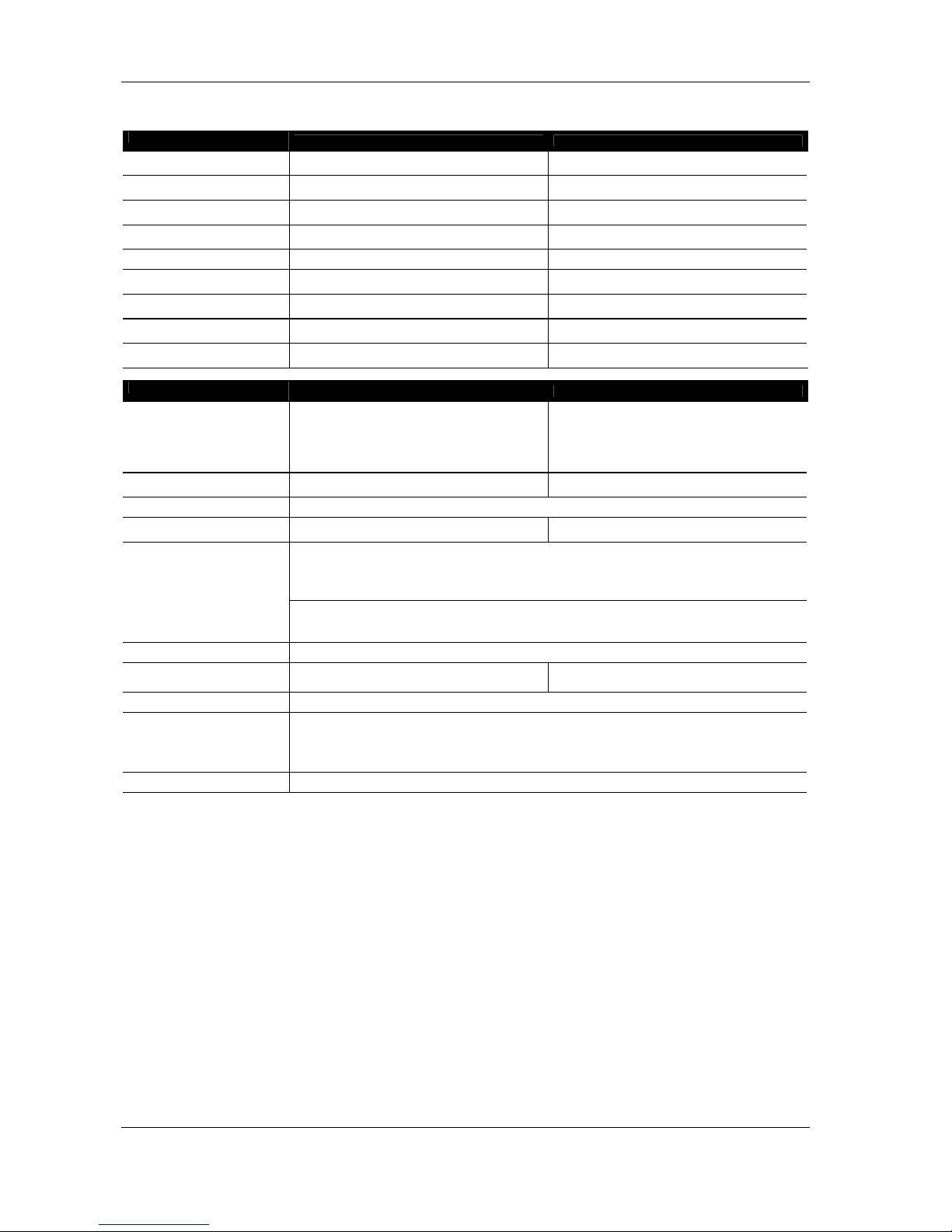
Alpha EM / EF
SYSTEM SPECS
ALPHA EM ALPHA EF
Frequency
Response [a]
220 Hz – 19 kHz ± 3 dB 40 Hz – 19 kHz ± 3 dB
Usable Range @6dB [a]
180 Hz – 20 kHz ± 6 dB 38 Hz – 20 kHz ± 6 dB
Sensitivity 1W @
1m [b]
107 dB SPL 107 dB SPL
Peak SPL @ 1m
[b]
140 dB Peak
LF: 142 dB Peak
MF/HF: 140 dB Peak
Dispersion [c]
75° x 30° 75° x 30°
Directivity: Q & DI
[c]
Q = 25 – DI = 14 dB (Nominal f > 630
Hz)
Q = 25 – DI = 14 dB (Nominal f > 630
Hz)
Cross-Over
Frequency
MF/HF: 2.2 kHz (Passive)
LF/MF: 210 Hz (Active)
MF/HF: 2.2 kHz (Passive)
Nominal
Impedance
8 ohms (7.5 min)
LF: 6 ohms (4.7 min)
MF/HF: 8 ohms (7.5 min)
Recommended
Amplifiers
700 to 1000 Watts into 8 ohms
MF: 900 to 1400 Watts into 6 ohms
MF/HF: 700 to 1000 Watts into 8 ohms
FEATURES
ALPHA EM ALPHA EF
Components
MF: 1 x 10" (24 cm) 8 ohms
HF: 1 x 3’’ Ceramic Driver, Titanium
diaphragm
Coaxial mounted wave guide
LF: 1 x 18’’ (46cm) 6 Ohms Composite
Curve
MF: 1 x 10" (24 cm) 8 ohms
HF: 1 x 3’’ Ceramic Driver, Titanium
diaphragm
Coaxial mounted wave guide
Height x Width x
Depth
400 x 689 x 754 mm Carpet version
(15 3/4" x 27 1/8 " x 29 11/16")
1200 x 689 x 754 mm Carpet version
(47 1/4" x 27 1/8 " x 29 11/16")
Shape
22.5° Trapezoid
Weight: Net
46.6 kg (99 Lb)
98 kg (209 Lb)
With wheel board: 105 kg (231 Lb)
Connectors
2 x 8 poles Speakon (In / Out)
1+ & 1- (Sub-bass S2)
2+ & 2- (Bass B1)
3+ & 3- (MF/HF)
4+ & 4- (NC)
1 x 4 poles Speakon (to B1 & S2)
1+ & 1- (Sub-bass S2))
2+ & 2- (Bass B1)
Construction
Baltic Birch with Dark Grey carpeting, Structured Black coating painting finish also available.
Handles
2 Metal Bar Handles 4 Metal Bar Handles
Front Finish
Acoustic Foam on hex perforated steel grid (77% transparent)
Flying points
(optional)
4 Flying Tracks on front (7 positions on 2° steps)
Top to bottom Steel Back plate
4 Flying Tracks on Back (Hinge fixing)
Internal top to bottom Steel links
Painted version without Flying Tracks also available
Fixed Installation
The X-BOW Flying Tracks can also receive standard Aircraft Flying Fittings.
As part of a policy of continual improvement, NEXO reserves the right to change specifications without notice.
[a] Response Curves and Data: Anechoic Far Field above 200 Hz, Half-space Anechoic below 200 Hz.
Usable Range Data: Frequency Response Capability with TD crossover slopes removed.
[b] Sensitivity & Peak SPL: will depend on spectral distribution. Measured with band limited Pink Noise.
Refers to the specified +/- 3 dB range. Data are for Speaker + Processor + recommended amplifier combinations.
[c] Directivity Curves and Data: 1/3 octave smoothed frequency response, normalised to On-Axis response.
Data obtained by computer processing on off-axis response curves.
Page 23
PAGE 23/37
TECHNICAL SPECIFICATIONS
ALPHA SERIES USER MANUAL V1.0
DATE: 14/01/00 18:27
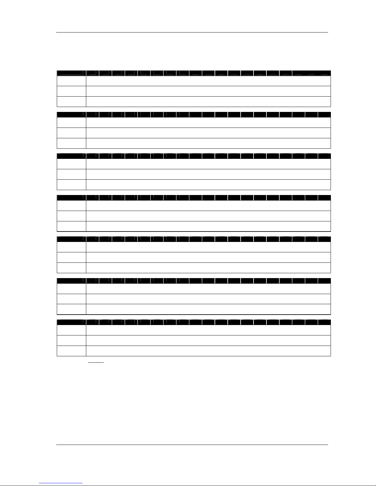
Directivity Tables
Off-Axis Attenuation from On-Axis Frequency Response (dB)
125 Hz
Angle / dB 0 10 20 30 40 50 60 70 80 90 100 110 120 130 140 150 160 170 180
B1+M3 hor 0.0 0.5 1.3 2.0 2.5 3.5 4.3 4.5 5.0 4.8 6.0 6.0 6.5 6.8 6.3 7.0 6.3
5.8 5.5
B1+M3 vert 0.0 0.3 0.5 1.5 2.0 2.8 3.5 4.3 4.8 5.5 6.0 6.8 6.8 6.0 7.0 6.5 6.0
5.5 5.5
B1+M8 hor 0.0 0.5 1.3 2.0 2.5 3.5 4.3 4.5 5.0 4.8 6.0 6.0 6.5 6.8 6.3 7.0 6.3 5.8 5.5
B1+M8 vert 0.0 0.3 0.5 1.5 2.0 2.8 3.5 4.3 4.8 5.5 6.0 6.8 6.8 6.0 7.0 6.5 6.0 5.5 5.5
EM/EF hor 0.0 0.3 0.5 1.0 2.0 2.5 3.3 4.0 4.5 5.0 5.5 6.3 6.0 6.0 5.8 5.3 4.5 4.3 4.0
EM/EF vert 0.0 0.0 0.3 0.5 1.0 1.5 2.0 2.8 3.5 4.0 4.8 5.5 6.0 6.0 5.8 5.0 4.5 4.3 4.0
250 Hz
Angle / dB 0 10 20 30 40 50 60 70 80 90 100 110 120 130 140 150 160 170 180
B1+M3 hor 0.0 0.3 1.0 2.0 3.0 4.3 5.5 6.8 8.0 8.5 9.5 9.8 9.8 10.0 9.5 8.8 8.0
7.5 7.5
B1+M3 vert 0.0 0.3 0.8 1.5 2.5 4.0 5.3 6.5 7.5 8.5 9.8 10.8 12.0 12.0 11.0 9.8 8.5
8.0 7.5
B1+M8 hor 0.0 0.3 0.8 2.0 3.0 4.3 6.0 7.0 8.0 8.8 9.3 10.0 10.5 10.3 10.0 9.3 8.0
7.5 7.8
B1+M8 vert 0.0 0.3 1.0 1.8 3.0 4.3 5.5 7.0 8.0 9.3 10.3 11.3 12.0 12.0 11.0 9.8 8.8
7.8 7.8
EM/EF hor 0.0 0.3 0.8 1.8 3.0 4.0 5.3 6.3 7.0 7.8 8.0 8.5 8.8 8.8 8.3 7.5 6.5 6.0 6.0
EM/EF vert 0.0 0.0 0.5 1.0 1.5 2.5 3.3 4.0 4.8 5.5 6.5 7.5 8.5 8.8 8.8 8.0 7.0 6.3 6.0
500 Hz
Angle / dB 0 10 20 30 40 50 60 70 80 90 100 110 120 130 140 150 160 170 180
B1+M3 hor 0.0 0.5 2.0 4.5 7.3 9.8 12.0 14.0 15.8 16.8 17.8 18.8 19.0 18.8 18.5 18.0 17.0 15.0 14.5
B1+M3 vert 0.0 0.5 2.0 4.3 6.8 9.3 11.8 13.5 15.0 16.3 17.3 18.3 19.0 20.0 20.5 21.0 19.3 16.0 14.5
B1+M8 hor 0.0 0.5 2.0 4.3 6.5 9.0 12.0 14.0 16.3 17.8 18.5 19.0 19.3 19.5 19.5 19.5 17.5 15.5 15.8
B1+M8 vert 0.0 0.5 2.0 4.0 6.5 8.8 11.3 13.5 15.5 16.8 17.5 18.3 19.3 20.5 21.5 21.8 19.5 16.5 15.8
EM/EF hor 0.0 0.5 2.0 4.0 6.5 9.3 11.8 14.0 15.8 17.0 17.0 17.3 17.8 18.0 17.8 16.3 14.3 12.5 12.0
EM/EF vert 0.0 0.3 1.0 1.8 3.0 4.5 6.0 7.5 8.8 10.0 11.0 11.3 12.0 13.0 15.0 16.3 14.5 12.8 12.0
1000 Hz
Angle / dB 0 10 20 30 40 50 60 70 80 90 100 110 120 130 140 150 160 170 180
B1+M3 hor 0.0 1.3 5.0 10.0 13.0 14.5 15.8 17.3 18.8 20.0 21.5 22.3 23.5 24.5 23.5 20.5 21.0 18.5 16.8
B1+M3 vert 0.0 1.8 6.0 10.8 12.3 13.0 14.3 15.5 17.3 18.5 19.5 20.5 21.5 22.0 22.8 23.5 26.3 20.5 16.8
B1+M8 hor 0.0 1.5 5.5 9.8 11.5 12.5 13.8 15.3 17.0 18.8 19.5 21.0 22.0 22.3 22.0 20.0 20.8 17.5 16.3
B1+M8 vert 0.0 1.8 6.5 11.0 11.5 12.0 13.3 15.0 16.5 17.8 18.5 20.0 21.0 21.3 21.8 21.5 20.5 19.5 16.3
EM/EF hor 0.0 2.0 6.3 9.8 9.5 9.5 10.3 11.3 12.5 13.5 14.3 15.3 16.5 17.5 18.8 17.3 18.8 19.0 17.0
EM/EF vert 0.0 0.8 2.5 5.0 8.0 10.8 13.0 15.3 17.5 19.3 20.3 21.0 21.5 22.0 23.0 23.0 21.3 19.0 17.0
2000 Hz
Angle / dB 0 10 20 30 40 50 60 70 80 90 100 110 120 130 140 150 160 170 180
B1+M3 hor 0.0 1.3 6.0 14.0 14.5 16.0 18.3 19.8 21.5 23.3 25.5 27.5 28.5 30.0 30.0 29.8 27.8 27.3 28.0
B1+M3 vert 0.0 1.8 7.0 14.3 15.8 17.0 20.0 21.8 23.3 24.5 25.8 27.0 28.3 29.0 29.0 29.3 29.5 29.3 28.0
B1+M8 hor 0.0 1.5 5.8 10.5 11.5 11.3 13.5 16.5 20.5 24.0 25.5 28.0 27.3 27.5 27.5 28.5 27.0 28.5 28.0
B1+M8 vert 0.0 2.3 7.5 12.5 15.0 16.0 18.0 20.5 22.5 24.5 25.8 27.0 28.0 29.0 27.8 26.8 29.0 29.5 28.0
EM/EF hor 0.0 1.5 4.5 7.8 7.8 8.0 10.0 12.5 15.5 18.0 19.5 20.0 21.5 22.8 23.0 23.8 25.5 25.8 24.0
EM/EF vert 0.0 1.8 5.5 10.5 14.5 16.5 18.3 20.0 22.0 24.0 25.5 26.3 27.0 28.0 29.3 28.0 26.5 25.0 24.0
4000 Hz
Angle / dB 0 10 20 30 40 50 60 70 80 90 100 110 120 130 140 150 160 170 180
M3 hor 0.0 2.0 6.5 11.3 16.0 19.5 22.5 25.5 28.8 31.8 34.5 37.3 38.3 39.8 40.5 40.3 40.5 38.0 37.8
M3 vert 0.0 2.3 6.8 12.3 16.5 19.0 22.5 25.5 29.5 32.0 34.5 36.8 38.3 39.3 39.3 40.0 39.5 38.8 37.8
M8 hor 0.0 1.0 3.8 6.8 11.3 14.3 18.0 21.0 25.0 28.8 31.0 33.0 34.3 35.0 36.0 37.0 38.0 39.5 38.0
M8 vert 0.0 2.0 5.8 11.0 15.5 20.0 23.3 27.0 30.0 33.0 34.8 36.5 37.3 38.0 39.0 40.0 41.0 40.5 38.0
EM/EF hor 0.0 1.5 3.8 5.5 6.8 9.3 12.3 16.0 19.8 23.8 26.5 28.3 29.3 30.0 31.0 33.8 33.0 33.5 32.3
EM/EF vert 0.0 2.8 7.8 12.8 16.3 19.3 21.8 24.0 26.0 28.3 30.0 31.0 32.5 33.8 34.5 35.0 34.8 34.0 32.3
8000 Hz
Angle / dB 0 10 20 30 40 50 60 70 80 90 100 110 120 130 140 150 160 170 180
M3 hor 0.0 1.5 7.0 13.3 18.5 22.3 25.0 29.5 34.8 39.0 42.8 45.3 45.5 47.8 48.8 47.0 48.0 46.3 47.3
M3 vert 0.0 1.8 7.0 13.5 18.8 21.5 25.0 28.5 33.8 38.0 40.5 42.5 44.5 45.5 46.3 47.3 48.0 49.0 47.3
M8 hor 0.0 0.3 2.0 6.3 11.8 15.0 19.0 22.5 28.0 31.8 40.5 43.0 44.0 45.0 46.0 47.0 48.0 49.0 47.5
M8 vert 0.0 1.8 5.8 11.3 16.5 20.8 24.3 29.0 32.0 35.0 42.0 44.0 45.0 46.0 47.0 48.0 49.0 47.0 47.5
EM/EF hor 0.0 0.8 3.0 6.0 8.0 11.5 14.5 18.5 24.3 30.0 33.8 36.3 37.0 39.3 40.5 41.8 41.8 42.5 42.0
EM/EF vert 0.0 3.3 9.5 15.5 20.0 23.3 24.5 26.5 30.8 34.3 36.0 38.0 38.8 39.8 40.0 41.5 41.5 40.8 42.0
NOTE: Those data are also available in electronic format. (EASE™ compatible) contact your
NEXO agent.
Page 24
PAGE 24/37
CURVES
ALPHA SERIES USER MANUAL V1.0
DATE: 14/01/00 18:27
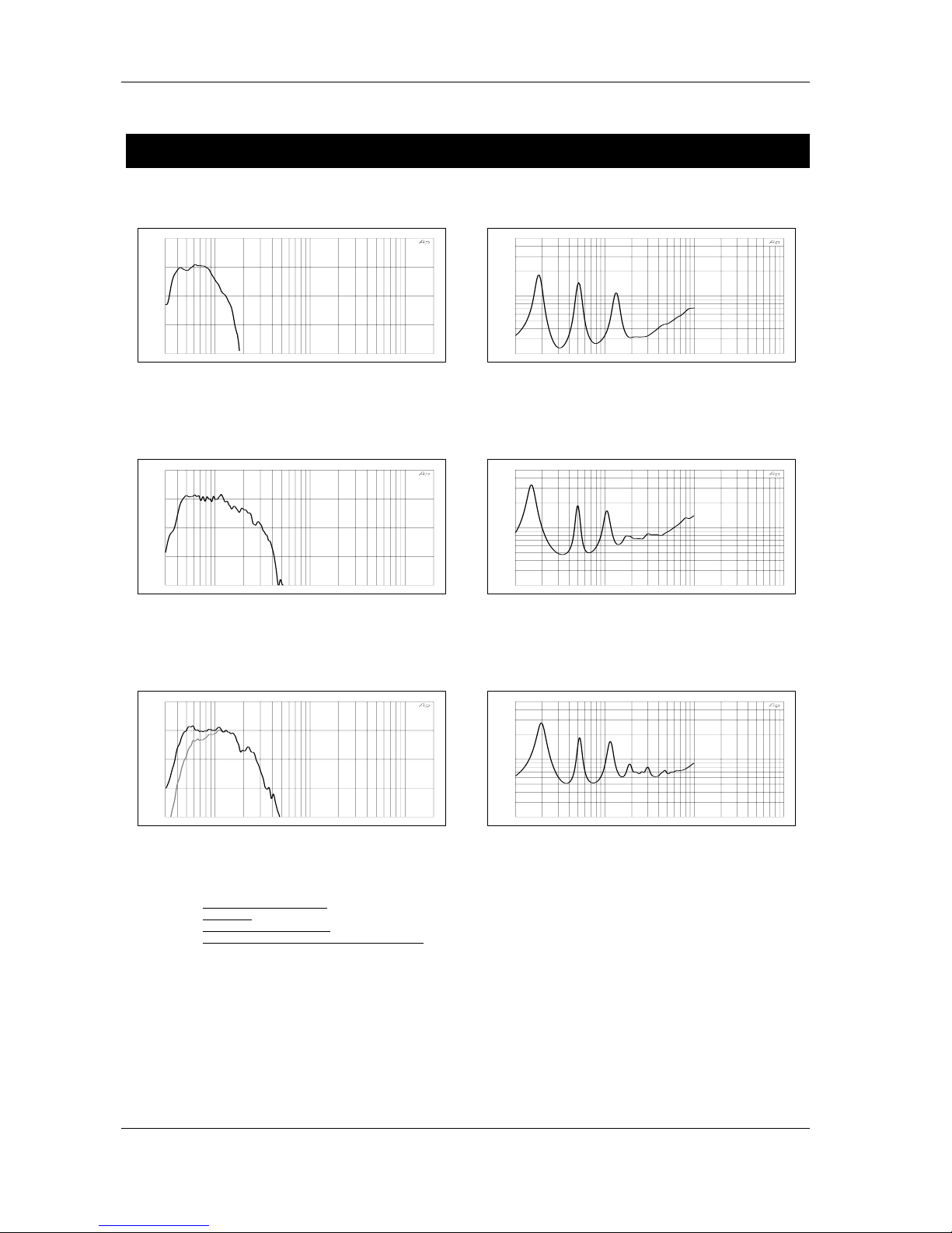
CURV ES
Alpha S2
30 100 1k 10k 20k
-30.00
-20.00
-10.00
0.0
10.000
On Axis Response Alpha S2 With SubTD Controller (dB)
• Figure 1: Frequency Response with Sub TDcontroller (dB)
10 100 1k 10k
2
10
50
Impedance Alpha S2 (Ohm)
• Figure 2: Impedance (Ohms)
Alpha B1-18
30 100 1k 10k 20k
-30.00
-20.00
-10.00
0.0
10.000
On Axis Response Alpha B1-18 With AlphaETD Controller (dB)
• Figure 3: Frequency Response with AlphaE TDcontroller (dB)
10 100 1k 10k
2
10
50
Impedance Alpha B1-18 (Ohm)
• Figure 4: Impedance (Ohms)
Alpha B1-15
30 100 1k 10k 20k
-30.00
-20.00
-10.00
0.0
10.000
On Axis Response Alpha B1-15 With AlphaTD Controller (Overlap/X-over)
• Figure 5: Frequency Response with Alpha TDcontroller (dB)
Black: Overlap Mode, Grey: X-Over mode
10 100 1k 10k
2
10
50
Impedance Alpha B1-15 (Ohm)
• Figure 6: Impedance (Ohms)
Frequency Response Curves: Anechoic Far Field above 200 Hz, Half-space Anechoic below 200 Hz.
Impedance:
Voltage to Current Ratio, Free Field measurement
Off-Axis Frequency Response:
1/3 octave smoothed frequency response, normalised to On-Axis response.
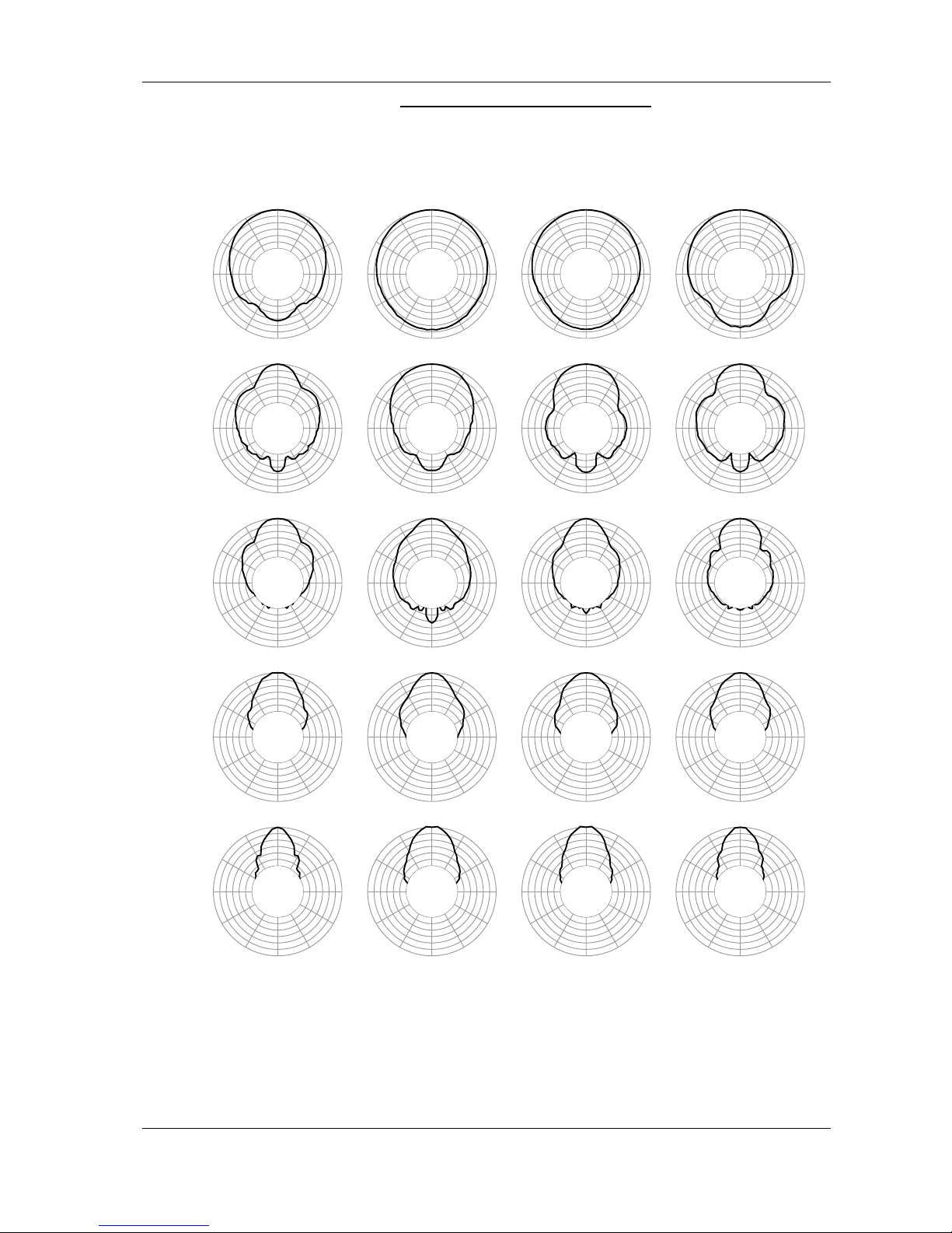
Directivity Curve, Coverage Angle and Polar Diagram
from computer processing on off-axis response curves.
Page 25
PAGE 25/37
CURVES
ALPHA SERIES USER MANUAL V1.0
DATE: 14/01/00 18:27
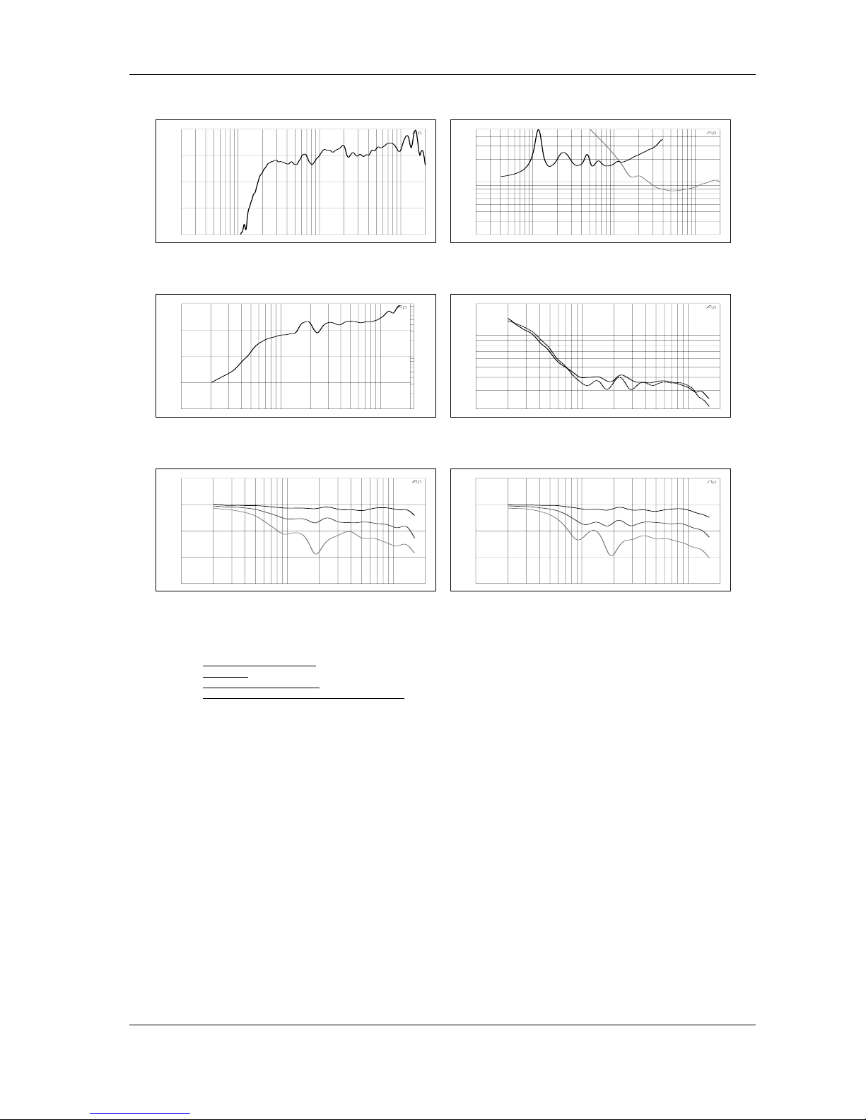
Alpha M3
20 100 1k 10k 20k
-30.00
-20.00
-10.00
0.0
10.000
On Axis Response Alpha M3 With AlphaTD Controller (dB)
• Figure 7: Frequency Response with Alpha TDcontroller (dB)
20 100 1k 10k 20k
2
10
50
Impedance Alpha M3 (Ohm)
• Figure 8: Impedance (Ohms) Black: MF, Grey: HF
100 1k 10k 20k
1
10
100
0.0
5.0000
10.000
15.000
20.000
Directivity Index (dB) & Q Alpha M3
• Figure 9: Directivity Index (dB) and Factor
100 1k 10k 20k
20
100
200
Coverage Angle Alpha M3 (Degree)
• Figure 10: Nominal Coverage @ –6 dB (Degrees)
100 1k 10k 20k
-30.00
-20.00
-10.00
0.0
10.000
Horizontal Off-Axis Response Alpha M3 (dB)
• Figure 11: Horizontal Off-Axis
Frequency Response @ 10, 20 & 30°
100 1k 10k 20k
-30.00
-20.00
-10.00
0.0
10.000
Vertical Off-Axis Response Alpha M3 (dB)
• Figure 12: Vertical Off-Axis
Frequency Response @ 10, 20 & 30°
Frequency Response Curves: Anechoic Far Field above 200 Hz, Half-space Anechoic below 200 Hz.
Impedance:
Voltage to Current Ratio, Free Field measurement
Off-Axis Frequency Response:
1/3 octave smoothed frequency response, normalised to On-Axis response.
Directivity Curve, Coverage Angle and Polar Diagram
from computer processing on off-axis response curves.
Page 26
PAGE 26/37
CURVES
ALPHA SERIES USER MANUAL V1.0
DATE: 14/01/00 18:27
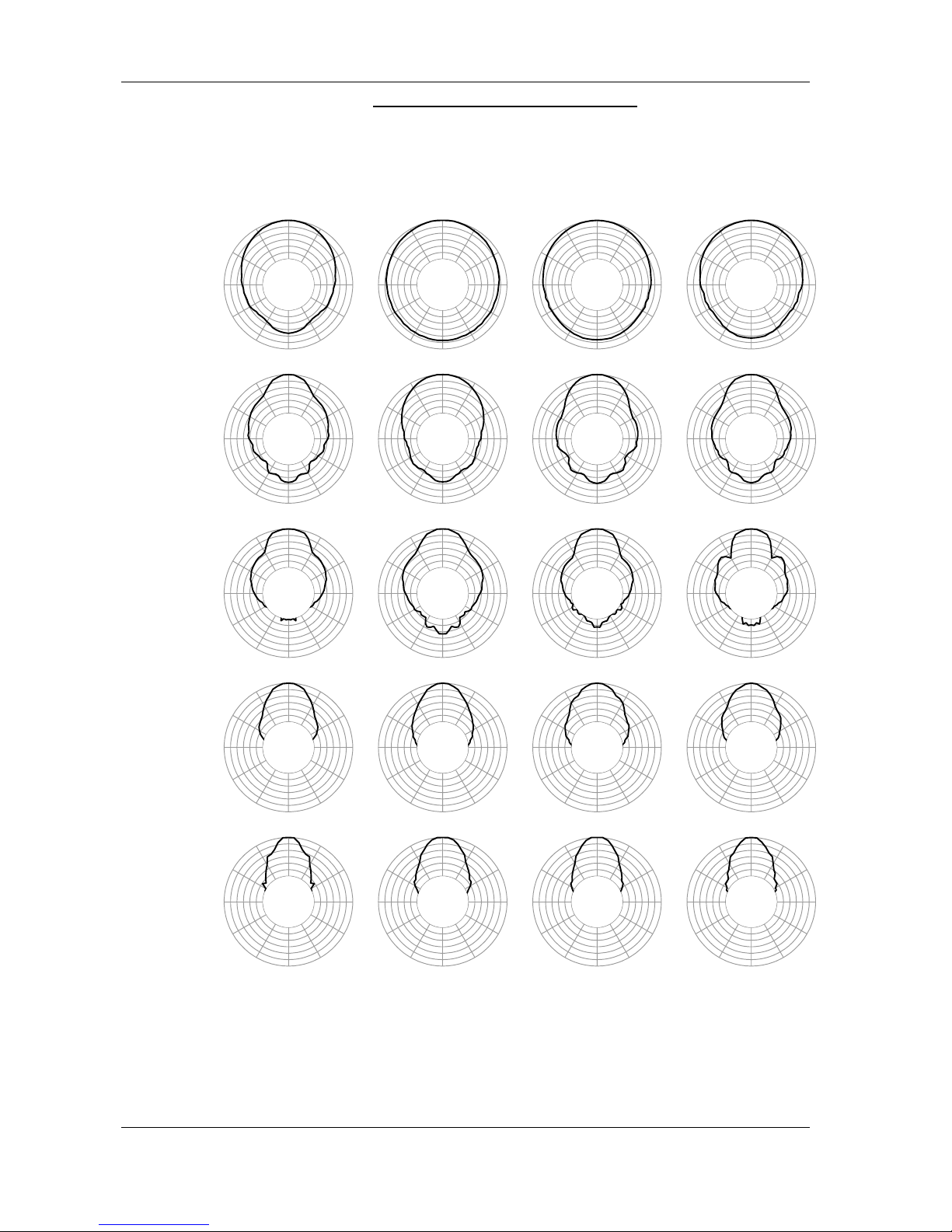
Alpha M3 - Horizontal Directivity (5dB / div.)
50 100 150 200 250 300 350 400 450 500 550
0
100
200
300
400
500
600
700
0°
30°
60°
90°
120°
150°
180°
210°
240°
270°
300°
330°
0°
30°
60°
90°
120°
150°
180°
210°
240°
270°
300°
330°
0°
30°
60°
90°
120°
150°
180°
210°
240°
270°
300°
330°
0°
30°
60°
90°
120°
150°
180°
210°
240°
270°
300°
330°
0°
30°
60°
90°
120°
150°
180°
210°
240°
270°
300°
330°
0°
30°
60°
90°
120°
150°
180°
210°
240°
270°
300°
330°
0°
30°
60°
90°
120°
150°
180°
210°
240°
270°
300°
330°
0°
30°
60°
90°
120°
150°
180°
210°
240°
270°
300°
330°
0°
30°
60°
90°
120°
150°
180°
210°
240°
270°
300°
330°
0°
30°
60°
90°
120°
150°
180°
210°
240°
270°
300°
330°
0°
30°
60°
90°
120°
150°
180°
210°
240°
270°
300°
330°
0°
30°
60°
90°
120°
150°
180°
210°
240°
270°
300°
330°
0°
30°
60°
90°
120°
150°
180°
210°
240°
270°
300°
330°
0°
30°
60°
90°
120°
150°
180°
210°
240°
270°
300°
330°
0°
30°
60°
90°
120°
150°
180°
210°
240°
270°
300°
330°
0°
30°
60°
90°
120°
150°
180°
210°
240°
270°
300°
330°
0°
30°
60°
90°
120°
150°
180°
210°
240°
270°
300°
330°
0°
30°
60°
90°
120°
150°
180°
210°
240°
270°
300°
330°
0°
30°
60°
90°
120°
150°
180°
210°
240°
270°
300°
330°
0°
30°
60°
90°
120°
150°
180°
210°
240°
270°
300°
330°
200 Hz 250 Hz 315 Hz 400 Hz
500 Hz 630 Hz 800 Hz 1 kHz
1.25 kHz 1.6 kHz 2 kHz 2.5 kHz
3.15 kHz 4 kHz 5 kHz 6.3 kHz
8 kHz 10 kHz 12.5 kHz 16 kHz
Page 27
PAGE 27/37
CURVES
ALPHA SERIES USER MANUAL V1.0
DATE: 14/01/00 18:27
Alpha M3 – Vertical Directivity (5dB / div.)
50 100 150 200 250 300 350 400 450 500 550
0
100
200
300
400
500
600
700
0°
30°
60°
90°
120°
150°
180°
210°
240°
270°
300°
330°
0°
30°
60°
90°
120°
150°
180°
210°
240°
270°
300°
330°
0°
30°
60°
90°
120°
150°
180°
210°
240°
270°
300°
330°
0°
30°
60°
90°
120°
150°
180°
210°
240°
270°
300°
330°
0°
30°
60°
90°
120°
150°
180°
210°
240°
270°
300°
330°
0°
30°
60°
90°
120°
150°
180°
210°
240°
270°
300°
330°
0°
30°
60°
90°
120°
150°
180°
210°
240°
270°
300°
330°
0°
30°
60°
90°
120°
150°
180°
210°
240°
270°
300°
330°
0°
30°
60°
90°
120°
150°
180°
210°
240°
270°
300°
330°
0°
30°
60°
90°
120°
150°
180°
210°
240°
270°
300°
330°
0°
30°
60°
90°
120°
150°
180°
210°
240°
270°
300°
330°
0°
30°
60°
90°
120°
150°
180°
210°
240°
270°
300°
330°
0°
30°
60°
90°
120°
150°
180°
210°
240°
270°
300°
330°
0°
30°
60°
90°
120°
150°
180°
210°
240°
270°
300°
330°
0°
30°
60°
90°
120°
150°
180°
210°
240°
270°
300°
330°
0°
30°
60°
90°
120°
150°
180°
210°
240°
270°
300°
330°
0°
30°
60°
90°
120°
150°
180°
210°
240°
270°
300°
330°
0°
30°
60°
90°
120°
150°
180°
210°
240°
270°
300°
330°
0°
30°
60°
90°
120°
150°
180°
210°
240°
270°
300°
330°
0°
30°
60°
90°
120°
150°
180°
210°
240°
270°
300°
330°
200 Hz 250 Hz 315 Hz 400 Hz
500 Hz 630 Hz 800 Hz 1 kHz
1.25 kHz 1.6 kHz 2 kHz 2.5 kHz
3.15 kHz 4 kHz 5 kHz 6.3 kHz
8 kHz 10 kHz 12.5 kHz 16 kHz
Page 28
PAGE 28/37
CURVES
ALPHA SERIES USER MANUAL V1.0
DATE: 14/01/00 18:27
Alpha M8
20 100 1k 10k 20k
-30.00
-20.00
-10.00
0.0
10.000
On Axis Response Alpha M8 With AlphaTD Controller (dB)
• Figure 13: Frequency Response with Alpha TDcontroller (dB)
20 100 1k 10k 20k
2
10
50
Impedance Alpha M8 (Ohm)
• Figure 14: Impedance (Ohms). Black: MF, Grey: HF
100 1k 10k 20k
1
10
100
0.0
5.0000
10.000
15.000
20.000
Directivity Index (dB) & Q Alpha M8
• Figure 15: Directivity Index (dB) and Factor
100 1k 10k 20k
20
100
200
Coverage Angle Alpha M8 (Degree)
• Figure 16: Nominal Coverage @–6 dB (Degrees)
100 1k 10k 20k
-30.00
-20.00
-10.00
0.0
10.000
Horizontal Off-Axis Response Alpha M8 (dB)
• Figure 17: Horizontal Off-Axis
Frequency Response @ 10, 20 & 30°
100 1k 10k 20k
-30.00
-20.00
-10.00
0.0
10.000
Vertical Off-Axis Response Alpha M8 (dB)
• Figure 18: Vertical Off-Axis
Frequency Response @ 10, 20 & 30°
Frequency Response Curves: Anechoic Far Field above 200 Hz, Half-space Anechoic below 200 Hz.
Impedance:
Voltage to Current Ratio, Free Field measurement
Off-Axis Frequency Response:
1/3 octave smoothed frequency response, normalised to On-Axis response.
Directivity Curve, Coverage Angle and Polar Diagram
from computer processing on off-axis response curves.
Page 29
PAGE 29/37
CURVES
ALPHA SERIES USER MANUAL V1.0
DATE: 14/01/00 18:27
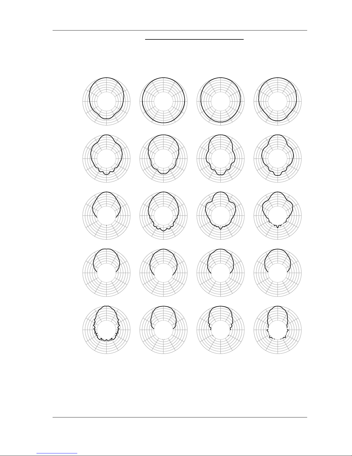
Alpha M8 – Horizontal Directivity (5dB / div.)
50 100 150 200 250 300 350 400 450 500 550
0
100
200
300
400
500
600
700
0°
30°
60°
90°
120°
150°
180°
210°
240°
270°
300°
330°
0°
30°
60°
90°
120°
150°
180°
210°
240°
270°
300°
330°
0°
30°
60°
90°
120°
150°
180°
210°
240°
270°
300°
330°
0°
30°
60°
90°
120°
150°
180°
210°
240°
270°
300°
330°
0°
30°
60°
90°
120°
150°
180°
210°
240°
270°
300°
330°
0°
30°
60°
90°
120°
150°
180°
210°
240°
270°
300°
330°
0°
30°
60°
90°
120°
150°
180°
210°
240°
270°
300°
330°
0°
30°
60°
90°
120°
150°
180°
210°
240°
270°
300°
330°
0°
30°
60°
90°
120°
150°
180°
210°
240°
270°
300°
330°
0°
30°
60°
90°
120°
150°
180°
210°
240°
270°
300°
330°
0°
30°
60°
90°
120°
150°
180°
210°
240°
270°
300°
330°
0°
30°
60°
90°
120°
150°
180°
210°
240°
270°
300°
330°
0°
30°
60°
90°
120°
150°
180°
210°
240°
270°
300°
330°
0°
30°
60°
90°
120°
150°
180°
210°
240°
270°
300°
330°
0°
30°
60°
90°
120°
150°
180°
210°
240°
270°
300°
330°
0°
30°
60°
90°
120°
150°
180°
210°
240°
270°
300°
330°
0°
30°
60°
90°
120°
150°
180°
210°
240°
270°
300°
330°
0°
30°
60°
90°
120°
150°
180°
210°
240°
270°
300°
330°
0°
30°
60°
90°
120°
150°
180°
210°
240°
270°
300°
330°
0°
30°
60°
90°
120°
150°
180°
210°
240°
270°
300°
330°
200 Hz 250 Hz 315 Hz 400 Hz
500 Hz 630 Hz 800 Hz 1 kHz
1.25 kHz 1.6 kHz 2 kHz 2.5 kHz
3.15 kHz 4 kHz 5 kHz 6.3 kHz
8 kHz 10 kHz 12.5 kHz 16 kHz
Page 30
PAGE 30/37
CURVES
ALPHA SERIES USER MANUAL V1.0
DATE: 14/01/00 18:27
Alpha M8 Vertical Directivity (5dB / div.)
50 100 150 200 250 300 350 400 450 500 550
0
100
200
300
400
500
600
700
0°
30°
60°
90°
120°
150°
180°
210°
240°
270°
300°
330°
0°
30°
60°
90°
120°
150°
180°
210°
240°
270°
300°
330°
0°
30°
60°
90°
120°
150°
180°
210°
240°
270°
300°
330°
0°
30°
60°
90°
120°
150°
180°
210°
240°
270°
300°
330°
0°
30°
60°
90°
120°
150°
180°
210°
240°
270°
300°
330°
0°
30°
60°
90°
120°
150°
180°
210°
240°
270°
300°
330°
0°
30°
60°
90°
120°
150°
180°
210°
240°
270°
300°
330°
0°
30°
60°
90°
120°
150°
180°
210°
240°
270°
300°
330°
0°
30°
60°
90°
120°
150°
180°
210°
240°
270°
300°
330°
0°
30°
60°
90°
120°
150°
180°
210°
240°
270°
300°
330°
0°
30°
60°
90°
120°
150°
180°
210°
240°
270°
300°
330°
0°
30°
60°
90°
120°
150°
180°
210°
240°
270°
300°
330°
0°
30°
60°
90°
120°
150°
180°
210°
240°
270°
300°
330°
0°
30°
60°
90°
120°
150°
180°
210°
240°
270°
300°
330°
0°
30°
60°
90°
120°
150°
180°
210°
240°
270°
300°
330°
0°
30°
60°
90°
120°
150°
180°
210°
240°
270°
300°
330°
0°
30°
60°
90°
120°
150°
180°
210°
240°
270°
300°
330°
0°
30°
60°
90°
120°
150°
180°
210°
240°
270°
300°
330°
0°
30°
60°
90°
120°
150°
180°
210°
240°
270°
300°
330°
0°
30°
60°
90°
120°
150°
180°
210°
240°
270°
300°
330°
200 Hz 250 Hz 315 Hz 400 Hz
500 Hz 630 Hz 800 Hz 1 kHz
1.25 kHz 1.6 kHz 2 kHz 2.5 kHz
3.15 kHz 4 kHz 5 kHz 6.3 kHz
8 kHz 10 kHz 12.5 kHz 16 kHz
Page 31
PAGE 31/37
CURVES
ALPHA SERIES USER MANUAL V1.0
DATE: 14/01/00 18:27
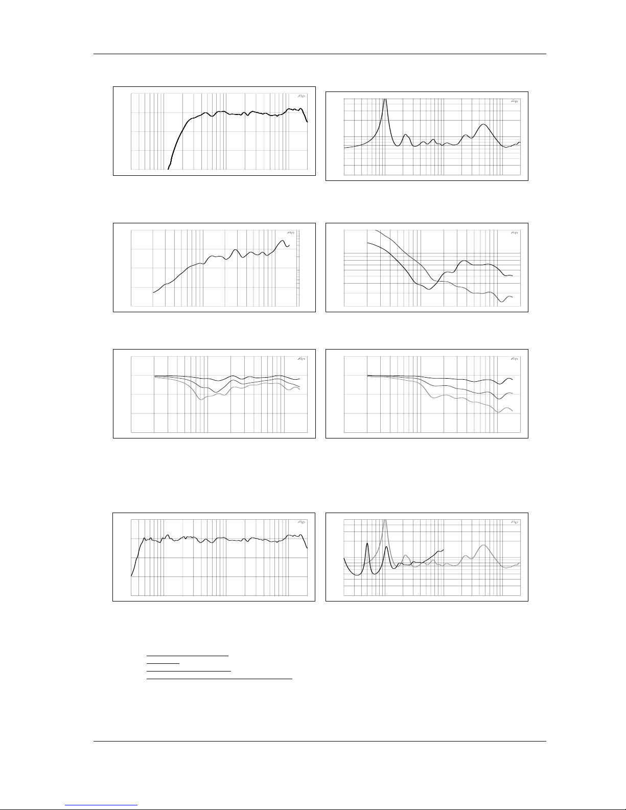
Alpha EM
30 100 1k 10k 20k
-30.00
-20.00
-10.00
0.0
10.000
On Axis Response Alpha EM With AlphaETD Controller (dB)
• Figure 19: Frequency Response with AlphaE TDcontroller
(dB)
20 100 1k 10k 20k
2
10
50
Impedance Alpha EM (Ohm)
• Figure 20: Impedance (Ohms)
100 1k 10k 20k
1
10
100
0.0
5.0000
10.000
15.000
20.000
Directivity Index (dB) & Q Alpha EM
• Figure 21: Directivity Index (dB) and Factor
100 1k 10k 20k
20
100
200
Coverage Angle Alpha EM (Degree)
• Figure 22: Nominal Coverage @–6 dB (Degrees)
100 1k 10k 20k
-30.00
-20.00
-10.00
0.0
10.000
Horizontal Off-Axis Response Alpha EM (dB)
• Figure 23: Horizontal Off-Axis
Frequency Response @ 10, 20 & 30°
100 1k 10k 20k
-30.00
-20.00
-10.00
0.0
10.000
Vertical Off-Axis Response Alpha EM (dB)
• Figure 24: Vertical Off-Axis
Frequency Response @ 10, 20 & 30°
Alpha EF
30 100 1k 10k 20k
-30.00
-20.00
-10.00
0.0
10.000
On Axis Response Alpha EF With AlphaETD Controller (dB)
• Figure 25: Frequency Response with AlphaE TDcontroller
(dB)
20 100 1k 10k 20k
2
10
50
Impedance Alpha EF (Ohm)
• Figure 26: Impedance (Ohms). Black: LF, Grey: MF+HF
Frequency Response Curves: Anechoic Far Field above 200 Hz, Half-space Anechoic below 200 Hz.
Impedance:
Voltage to Current Ratio, Free Field measurement
Off-Axis Frequency Response:
1/3 octave smoothed frequency response, normalised to On-Axis response.
Directivity Curve, Coverage Angle and Polar Diagram
from computer processing on off-axis response curves.
Page 32
PAGE 32/37
CURVES
ALPHA SERIES USER MANUAL V1.0
DATE: 14/01/00 18:27
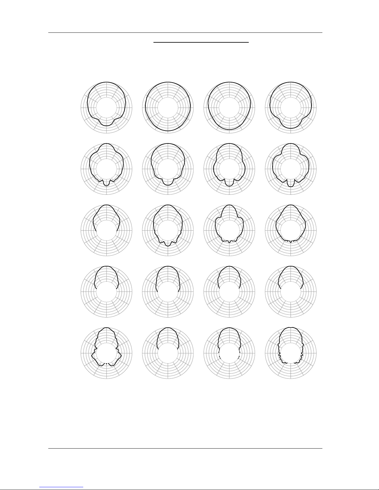
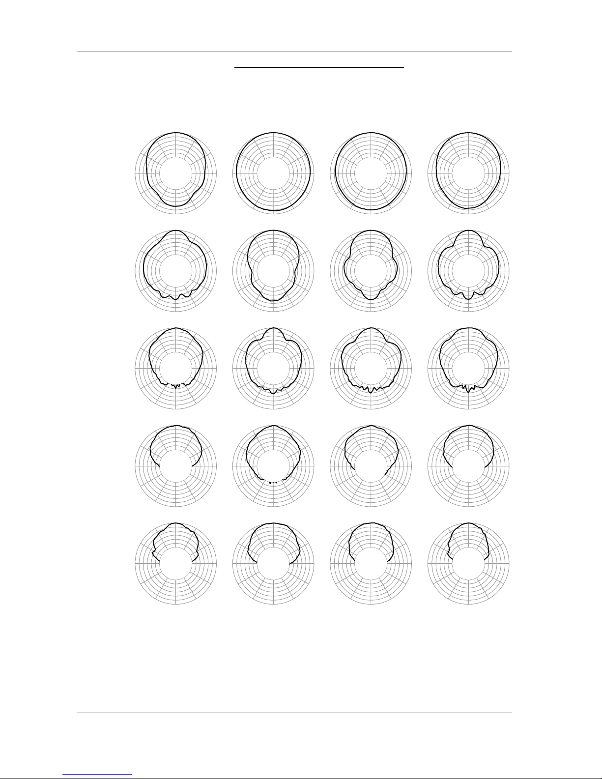
Alpha EM – Horizontal Directivity (5dB / div.)
50 100 150 200 250 300 350 400 450 500 550
0
100
200
300
400
500
600
700
0°
30°
60°
90°
120°
150°
180°
210°
240°
270°
300°
330°
0°
30°
60°
90°
120°
150°
180°
210°
240°
270°
300°
330°
0°
30°
60°
90°
120°
150°
180°
210°
240°
270°
300°
330°
0°
30°
60°
90°
120°
150°
180°
210°
240°
270°
300°
330°
0°
30°
60°
90°
120°
150°
180°
210°
240°
270°
300°
330°
0°
30°
60°
90°
120°
150°
180°
210°
240°
270°
300°
330°
0°
30°
60°
90°
120°
150°
180°
210°
240°
270°
300°
330°
0°
30°
60°
90°
120°
150°
180°
210°
240°
270°
300°
330°
0°
30°
60°
90°
120°
150°
180°
210°
240°
270°
300°
330°
0°
30°
60°
90°
120°
150°
180°
210°
240°
270°
300°
330°
0°
30°
60°
90°
120°
150°
180°
210°
240°
270°
300°
330°
0°
30°
60°
90°
120°
150°
180°
210°
240°
270°
300°
330°
0°
30°
60°
90°
120°
150°
180°
210°
240°
270°
300°
330°
0°
30°
60°
90°
120°
150°
180°
210°
240°
270°
300°
330°
0°
30°
60°
90°
120°
150°
180°
210°
240°
270°
300°
330°
0°
30°
60°
90°
120°
150°
180°
210°
240°
270°
300°
330°
0°
30°
60°
90°
120°
150°
180°
210°
240°
270°
300°
330°
0°
30°
60°
90°
120°
150°
180°
210°
240°
270°
300°
330°
0°
30°
60°
90°
120°
150°
180°
210°
240°
270°
300°
330°
0°
30°
60°
90°
120°
150°
180°
210°
240°
270°
300°
330°
200 Hz 250 Hz 315 Hz 400 Hz
500 Hz 630 Hz 800 Hz 1 kHz
1.25 kHz 1.6 kHz 2 kHz 2.5 kHz
3.15 kHz 4 kHz 5 kHz 6.3 kHz
8 kHz 10 kHz 12.5 kHz 16 kHz
Page 33
PAGE 33/37
CURVES
ALPHA SERIES USER MANUAL V1.0
DATE: 14/01/00 18:27
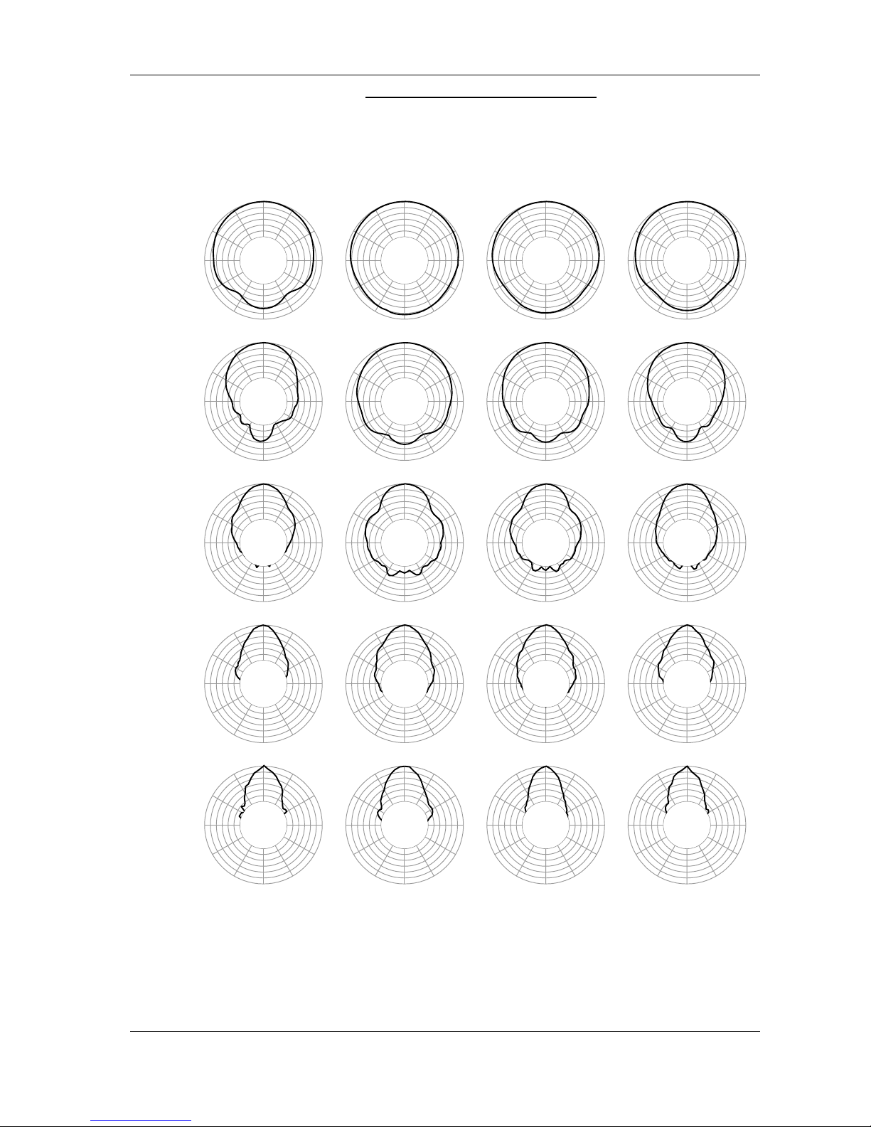
Alpha EM – Vertical Directivity (5dB / div.)
50 100 150 200 250 300 350 400 450 500 550
0
100
200
300
400
500
600
700
0°
30°
60°
90°
120°
150°
180°
210°
240°
270°
300°
330°
0°
30°
60°
90°
120°
150°
180°
210°
240°
270°
300°
330°
0°
30°
60°
90°
120°
150°
180°
210°
240°
270°
300°
330°
0°
30°
60°
90°
120°
150°
180°
210°
240°
270°
300°
330°
0°
30°
60°
90°
120°
150°
180°
210°
240°
270°
300°
330°
0°
30°
60°
90°
120°
150°
180°
210°
240°
270°
300°
330°
0°
30°
60°
90°
120°
150°
180°
210°
240°
270°
300°
330°
0°
30°
60°
90°
120°
150°
180°
210°
240°
270°
300°
330°
0°
30°
60°
90°
120°
150°
180°
210°
240°
270°
300°
330°
0°
30°
60°
90°
120°
150°
180°
210°
240°
270°
300°
330°
0°
30°
60°
90°
120°
150°
180°
210°
240°
270°
300°
330°
0°
30°
60°
90°
120°
150°
180°
210°
240°
270°
300°
330°
0°
30°
60°
90°
120°
150°
180°
210°
240°
270°
300°
330°
0°
30°
60°
90°
120°
150°
180°
210°
240°
270°
300°
330°
0°
30°
60°
90°
120°
150°
180°
210°
240°
270°
300°
330°
0°
30°
60°
90°
120°
150°
180°
210°
240°
270°
300°
330°
0°
30°
60°
90°
120°
150°
180°
210°
240°
270°
300°
330°
0°
30°
60°
90°
120°
150°
180°
210°
240°
270°
300°
330°
0°
30°
60°
90°
120°
150°
180°
210°
240°
270°
300°
330°
0°
30°
60°
90°
120°
150°
180°
210°
240°
270°
300°
330°
200 Hz 250 Hz 315 Hz 400 Hz
500 Hz 630 Hz 800 Hz 1 kHz
1.25 kHz 1.6 kHz 2 kHz 2.5 kHz
3.15 kHz 4 kHz 5 kHz 6.3 kHz
8 kHz 10 kHz 12.5 kHz 16 kHz
Page 34
PAGE34/37
DIMENSIONS
ALPHA SERIES USER MANUAL V1.0
DATE: 14/01/00 16:23
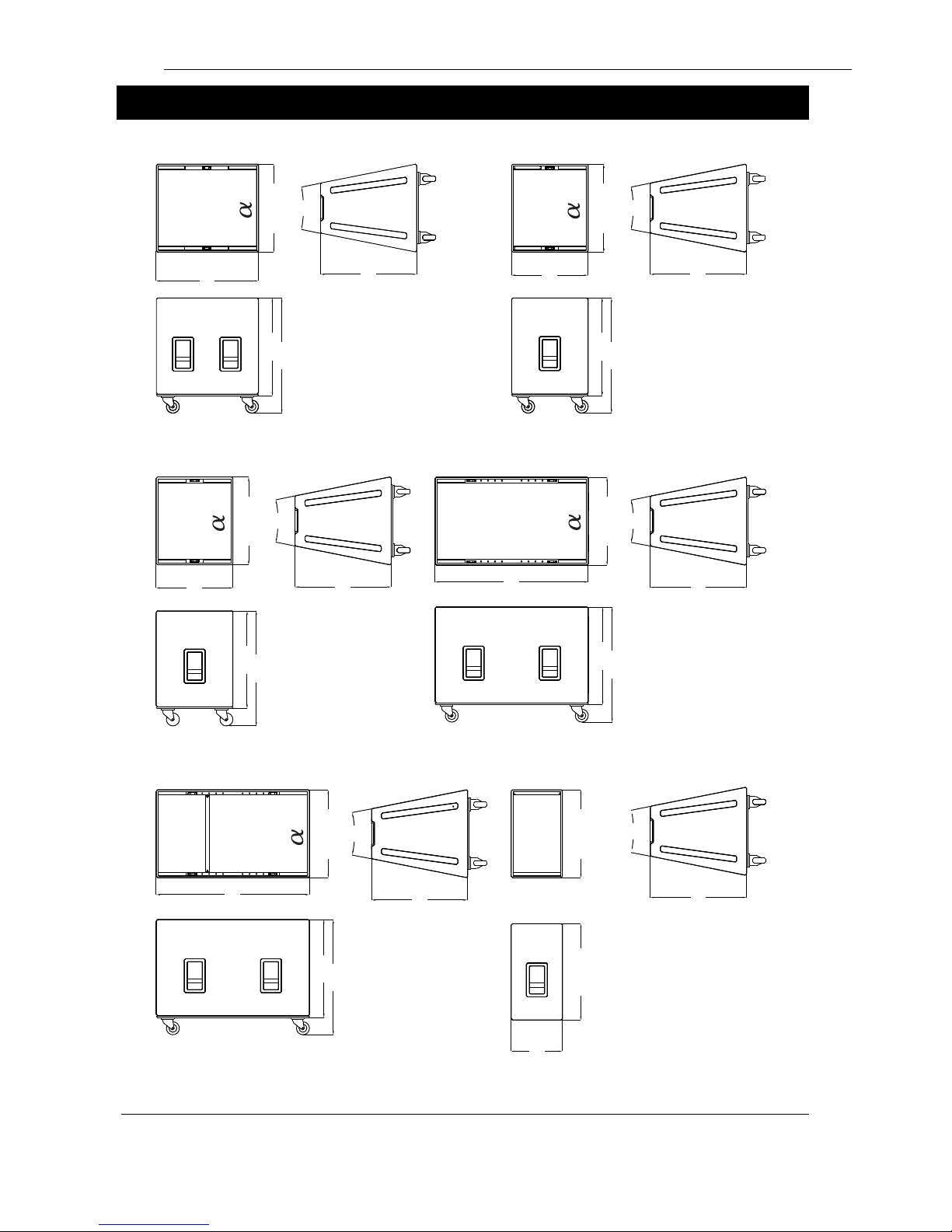
DIMENSIONS
800
[31.49"]
688.77
[27 1/8"]
22.5°
754
[29 11/16"]
762
[30"]
889
[35"]
754
[29 11/16"]
22.5°
688.77
[27 1/8"]
762
[30"]
889
[35"]
600
[23 5/8"}
22.5°
754
[29 11/16"]
688.77
[27 1/8"]
22.5°
754
[29 11/16"]
688.77
[27 1/8"]
762
[30"]
889
[35"]
762
[30"]
889
[35"]
1200
[47 1/4"]
600
[23 5/8"]
688.77
[27 1/8"]
754
[29 11/16"]
22.5°
688.77
[27 1/8"]
1200
[47 1/4"]
889
[35"]
762
[30"]
754
[29 11/16"]
400
[15.74"]
e
e
22.5°
754
[29 11/16"]
Page 35
PAGE 35/37
TRANSPORT
ALPHA SERIES USER MANUAL V1.0
DATE: 14/01/00 16:23
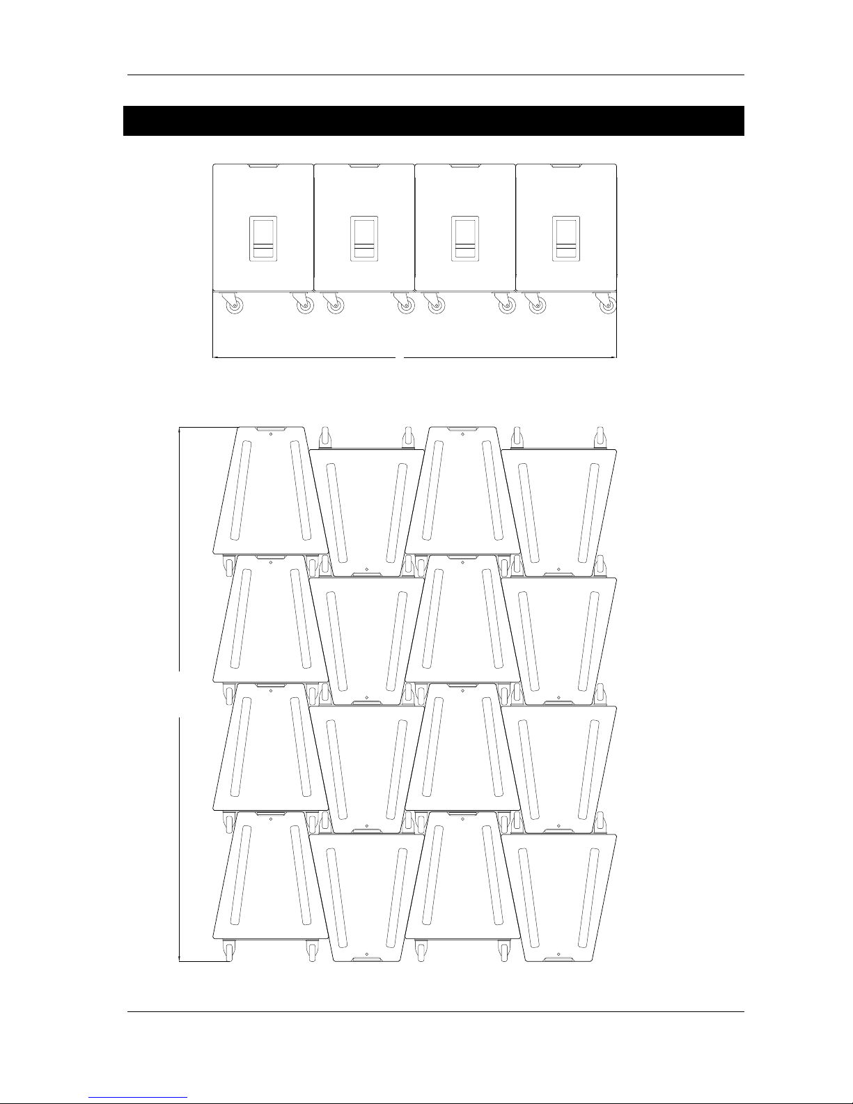
TRANSPORT
3175 [125"]
2400 [94 1/2"]
SIDE VIEW
TOP VIEW
Page 36
PAGE36/37
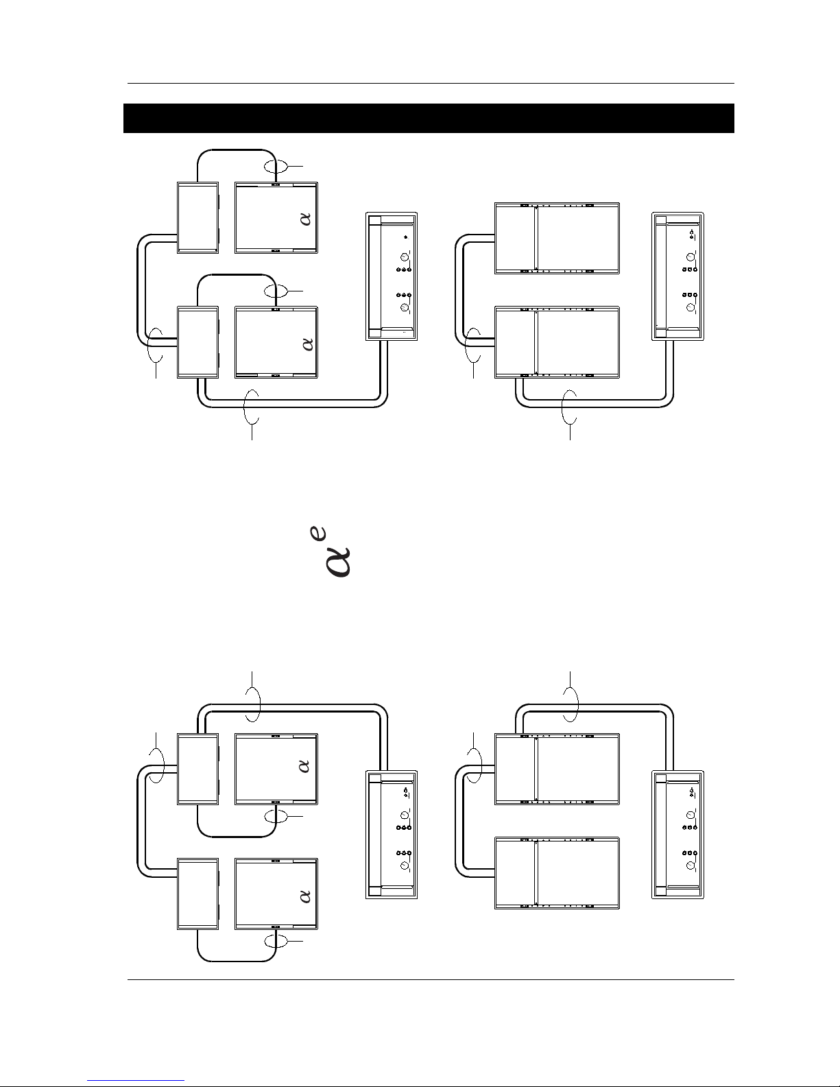
CONNECTION DIAGRAMS
ALPHA SERIES USER MANUAL V1.0
DATE: 14/01/00 16:23
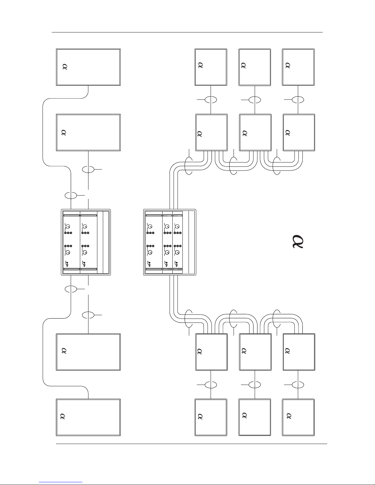
Connection Diagrams
900 to 1400 Watts into 6 ohms
700 to 1000 Watts into 8 ohms
ALPHA EM
ALPHA B1-18
Recommended Amplifiers
e
SP4 CABLE
SP8 CABLE
NX241 TDcontroller
B1-18
e
ee
e
e
e
e
B1-18
B1-18
B1-18
SP8 CABLE
SP8 CABLE
SP8 CABLE
SP8 CABLE
SP8 CABLE
SP8 CABLE
SP8 CABLE
SP4 CABLE
SP4 CABLE
SP4 CABLE
NX241 TDcontroller
NX241 TDcontroller
NX241 TDcontroller
LF
LF
LF
LF
HF / MF
HF / MF
HF / MF
HF / MF
Page 37
PAGE 37/37
CONNECTION DIAGRAMS
ALPHA SERIES USER MANUAL V1.0
DATE: 14/01/00 18:27
B1-18
B1-18
B1-18
B1-18
B1-18
B1-18
M3 / M8
M3 / M8
M3 / M8
M3 / M8
M3 / M8
M3 / M8
S2
S2
S2
S2
SP8 CABLE
SP8 CABLE
SP8 CABLE
SP8 CABLE
SP8 CABLE
SP8 CABLE
SP4 CABLE
SP4 CABLE
SP4 CABLE SP4 CABLE
SP4 CABLE
SP4 CABLE
SP4 CABLE
SP4 CABLE
SP4 CABLE
SP4 CABLE
NX241 TDcontroller
NX241 TDcontroller
900 to 1400 Watts into 6 ohms
350 to 500 Watts into 12 ohms
ALPHA M3 -HF
ALPHA B1-18 / B1-15
Recommended Amplifiers
650 to 900 Watts into 12 ohms
ALPHA M3 -MF
1800 to 2400 Watts into 3 ohms
ALPHA S2
Page 38

Quick ref guide Alpha TDcontroller
Release : 0
Date : 03/12/99
Alpha TDcontroller
-
Quick reference guide
(Full user manual is coming soon !)
I. Read before use
The Alpha TDcontroller is designed to be used with the Alpha M4 and Alpha B1 speaker cabinets. Its
main functions are :
• To optimize the response of the system
• To split the signal into 3 frequency bands (LF, MF & HF)
• Active protection of the cabinets by dynamic audio signal processing (Temperature and
Displacement servo control)
• Reduction of amplifier overload (independent Peak limiter function on each channel)
Alpha TDcontroller also features :
• Global switchable output level
• Individual gain control on each channel
• High CMRR balanced input
• High current drive output stages
• User LF EQ
• Enhanced protection facility provided for additional safety margin when extended periods of
overload are anticipated
As with similar devices, the Alpha TDcontroller is intended to be inserted between the Audio source
(console, preamplifier, etc...) and the power amplifier.
WARNING : Sense lines MUST be wired in order to ensure the protection of your system. Failing
to do so may damage your speaker.
II. Front Panel
Most front panel functions and indicators are located inside 3 distinct windows : left-hand areas (with
upper label Eq & αLF) relates to functions and indicators dedicated to the B1 cabinet, while mid & righthand window (upper label αMF & αHF) contain indicators concerning servo control operation for the
Alpha M4
II.1. Wideband / Xover Push-button
This button is intended to modify the high pass filtering of the Alpha B1 cabinet.
Page 39

Error! Style not defined.
_________________________________________________________________________________________________
__
p.2
Quick ref guide Alpha TDcontroller
Release : 0
Date : 03/12/99
In the « Wideband » position the cabinet is exploited to its maximum capacity. This position should be
used if the system is used in the 3WAY mode. It can also be used along with the Alpha S2 Subbass, and
in that case there will be a boost in the cross over area.
The « Cross over » position is recommended while using the Alpha S2 Subbass (4 WAY mode). Your
main system will not be as stressed, and the tonal balance will be more « natural ».
II.2. LF Eq
The LF Eq trim allows you to tune a shelving filter (Fc 500Hz), in order to increase or decrease the bass
section (this trim will act on both M4 & B1 output). This function may be very useful to compensate the
coupling effect that vary according to the structure and size of your array.
The range is -/+ 6dB.
II.3. LEDs
II.3.a. Amplifier control
The green Senses LED indicates signal presence at sense input on each channel, allowing visual control
of the return connection from the amplifier output.
The red Pk LED indicates Peak limiter action reducing excessive peak voltage or levels capable of
overloading the amplifier.
II.3.b. Protection indicator
Yellow LED lighting up indicates that temperature or displacement protections are in action on the
relevant channel.
II.3.c. Power LED
At the leftmost extremity of the TDcontroller a green LED shows if the unit is powered.
II.4. Peak Limiter adjustments
The Alpha TDcontroller features three independent peak limiter trims which allows you to tune the peak
limiter according to the power of the amp. The peak limiter has no real protection function, it must be
tuned to avoid the clipping of the amp which could generate some strange artifacts.
To set the peak limiter at the correct value you can either turn the trimmer clockwise until the red LED
lights at the same time that the clipping LED of the amp, or use the graduation (power value given under
8Ω).
II.5. Gain control
Three 12 dB range trimmers are provided to set the gain each channels. This gain control is useless if
you are using amplifiers having the same gain. If you’re using constant sensitivity (1.4V or 0.7V) with
different amps powers, you will have to correct the gain difference between the amplifiers.
The factory position is mid (detent) which correspond to a 0 dB gain
Page 40

Error! Style not defined.
_________________________________________________________________________________________________
p.3
Quick ref guide Alpha TDcontroller
Release : 0
Date : 03/12/99
III. Rear Panel
III.1. Audio Inputs
Signal is applied between pins 2 and 3, pin 1 being grounded. As a result of the balanced nature of the
outputs (and providing that balancing is respected by way of the connection to the amplifier), there is no
hot or cold pin - the TDcontroller being neutral regarding the polarity of the signal.
III.2. Earth Lift
The push button labeled « Earth Lift » allows connection (depressed position), or disconnection (out
position) between the signal ground and the mains earth, which is itself linked to the chassis. Using this
button may help to eliminate hum due to ground loops created in the system.
III.3. Audio Outputs
The audio outputs are the three 3-pin male XLRs located in the area labeled Audio OUT.
Signal is applied between pins 2 and 3, pin 1 being connected to ground.
When used with an amplifier with balanced inputs Amplifier, the wiring of the output XLR is simply pin to
pin (1 to 1, etc..), the polarity of the signal being thus respected if the source connected to the input is
also balanced.
III.4. Output Level Switch
The three gain values available are +10/+6/0 dB.
+6dB is the recommended factory setting.
III.5. Sense inputs
The sense inputs of the three channels are arranged on a six pole barrier strip set into the rear panel
within the area labeled Sense IN. The Sense inputs are intended for the output signals of the amplifiers
driving one cabinet each of the channel being used.
Input sense connection is obligatory for proper operation of the servo-control system. cabinets will NOT
BE PROTECTED AT ALL if the sense lines are not connected.
III.6. Voltage selector
According to CEI65 and UL1419 norms, an external voltage selector is provided at the back of the unit. It
will allow the controller to works under both normalized voltage (230V and 115V).
WARNING : Changing the voltage rate means also changing the fuse and power cord. (Safety
norms concerning cables are changing according the voltage)
III.7. Fuse holder
When necessary the fuse should be replaced in any case by a fuse of the same rating
• for 230V : T100mAL250V
• for 115V : T200mAL250V
Page 41

Error! Style not defined.
_________________________________________________________________________________________________
__
p.4
Quick ref guide Alpha TDcontroller
Release : 0
Date : 03/12/99
III.8. Mains Socket
WARNING : This appliance must be earthed.
The socket is compatible with mains supply flexible cords which comply with IEC Publication 227.
IV. Functions requiring the opening of the
TDcontroller
IV.1. Enhanced protection trimmers
The embedded trimmers (Red wheel) are used to change the thresholds of the protection system.
TR13 affect the threshold of the HF (active) and Right (passive) protections
TR15 affect the threshold of the LF (active) and Left (passive) protections
TR18 affect the threshold of the SUB protections
It is not recommended to increase the threshold. (Marked « - ») as the protections will be lowered.
In the mid position the speaker protections will be set for normal operation (This is the factory set
position). When turned fully clockwise (marked +), protections will be increased ; e.g. this setting should
be used where the system is operating under harsh conditions (identical gain for each amp is not
checked ) Intermediate positions of the trimmer can also be used and will be recommended in cases of
extended periods of overload (e.g. in some discotheque applications).
V. Setting-Up Advice
V.1. Recommendations for wiring the Sense lines
The impedance of the sense inputs of the TDcontroller being quite high, the currents are low and
therefore ordinary line cable can be used. If the unit is housed in the amp racks an unshielded cable can
be used.
Page 42

France
NEXO S.A.
154 Allée des Erables
ZAC de PARIS NORD II BP 50107
F-95950 ROISSY CDG CEDEX
Tel: +33 1 48 63 19 14
Fax: +33 1 48 63 24 61
Email: [email protected]
USA
NEXO USA Inc.
2165 Francisco Blvd.
Suite E2
San Rafael CA 94901
Tel: +1 415 482 6600
Fax: +1 415 482 6110
Email: [email protected]
UK
NEXO limited
9 Lyon Road
Walton-on-Thames
Surrey KT12 3PU
Tel: +44 1932 886 007
Fax: +44 1932 886 008
Email: [email protected]
FAR EAST
NEXO Far East Ltd
101 Lorong, 23 Geyland
#06-04 Prosper House
Singapore 388399
Tel: +65 742 5660
Fax: +65 742 8050
Email: [email protected]
 Loading...