

Page 1
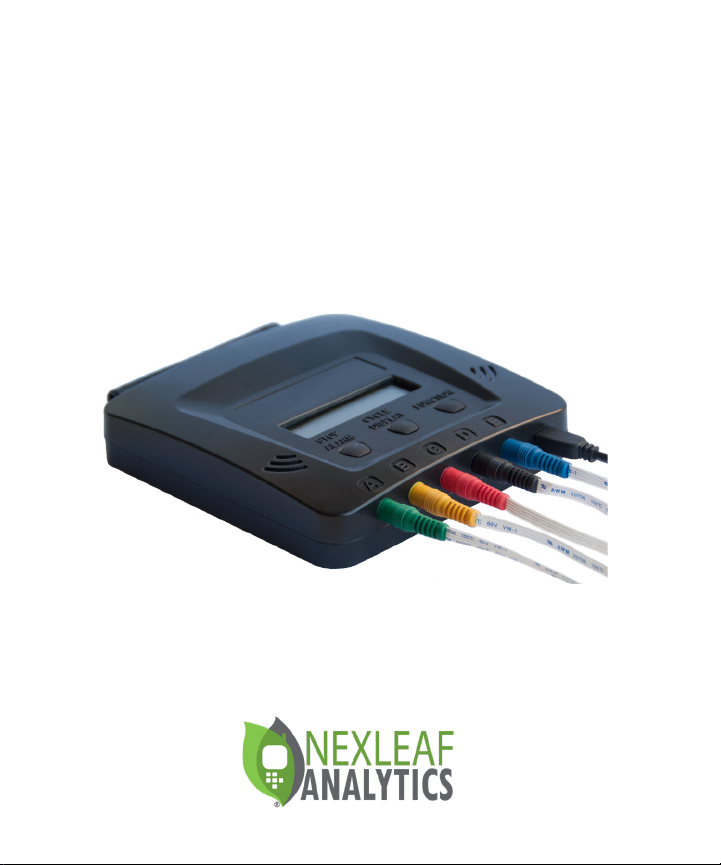
Set Up and Operations Guide
Page 2

Page 3

TABLE OF CONTENTS
Get to Know Your CT5 ..... 6
Setting Up Your CT5 ..... 9
Turning on the CT5 ..... 15
Understanding Each Button ..... 17
Resetting ..... 22
Booting Up the CT5 ..... 25
Installation and Troubleshooting ..... 30
3
Page 4

HELLO, COLDTRACE 5
ColdTrace has 3 core components:
1. ColdTrace 5 (CT5) device which sends temperature and power
data to a dashboard via GPRS and alerts via SMS and email when
fridge temperatures get too hot or too cold.
2. A secure web-based dashboard that allows remote access to
real-time temperature and provides customizable analytics and
report-generating tools to track fridge performance.
3. Standard Operating Procedures (SOPs) and training guides
for nurses, maintenance technicians, regional supervisors, and
Ministries of Health.
CONTACT YOUR RTM DEPLOYMENT ADVISOR
OR NEXLEAF AT: [email protected]
4
Page 5

PRE-INSTALLATION CHECKLIST
• Check the power situation of the health facility and if they have
a solar panel, nd out if that can be used for CT5. For health
facilities that need solar power (with batteries or direct), a
DC-to-DC converter is needed if there is no power inverter to
support the standard CT5 wall power plug.
• Opt for the right mobile service provider and procure SIM card
with M2M plan & post-pay option (preferred). Avoid the pre-pay
option if possible as topping up the SIM for CT5 every month
may prove to be dicult.
• CT5 needs less than 2 MB/ 150 SMS monthly may be needed to
perform. NOTE: If more than 2 people subscribe to receive SMS
alerts from the device, then more than 150 SMS are needed.
• Work with Nexleaf to identify the best SMS Gateway solution.
• Purchase surge-protected extension cords.
GENERAL CHECKLIST
Clinic power set up determined
SIM card plan with 2 MB/150 SMS monthly (for 1 person
receiving alerts) purchased
Preferably a M2M and post paid SIM card
SIM card size: Micro SIM (3FF)
SMS Gateway solution congured
Surge-protected extension cords purchased
5
Page 6

GET TO KNOW YOUR CT5
6
Page 7
KNOW YOUR CT5
Main Components
1
Accessories
2
STOP
CYCLE
ALARM
DISPLAY
FUNCTION
3
4 5 6
A B C D E
7
10
9
8
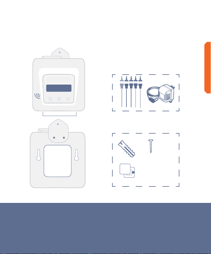
1. Antenna
2. Front display
3. Alarm buzzer
4. Stop Alarm button
5. Cycle Display button
GET TO KNOW YOUR CT5
Mounting Accessories
x3 x3
x8
6. Function button
7. Sensor ports - up to 5 sensors
8. Power port
9. Back panel
10. Installation hook
7
Page 8
GET TO KNOW YOUR CT5
KNOW YOUR CT5
Accessories
Accessories
2
STOP
CYCLE
ALARM
DISPLAY
FUNCTION
A B C D E
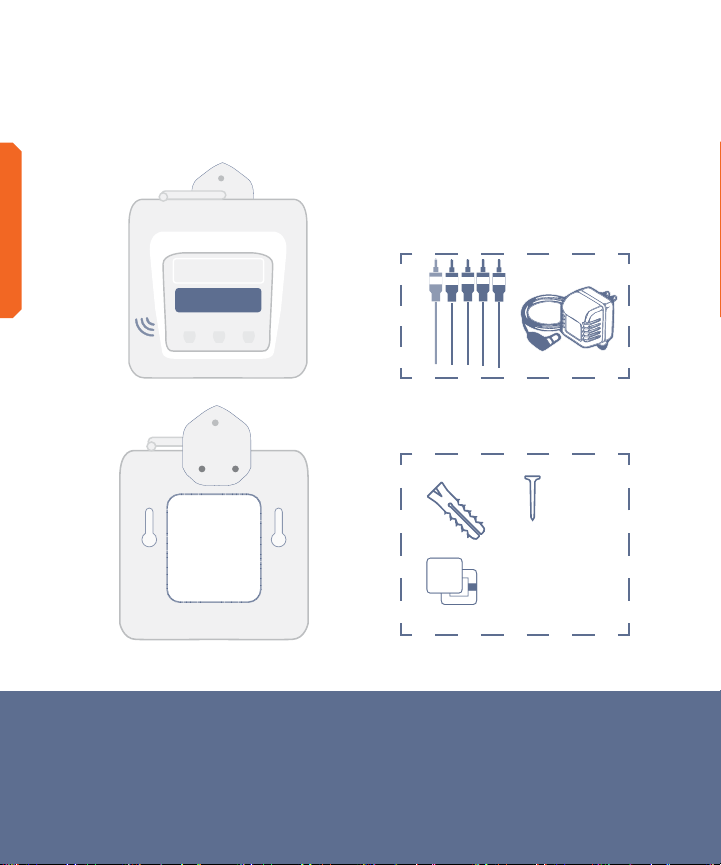
1. Sensor connection cable
2. Power adapter
8
1
Mounting Accessories
3
x3 x3
4
x8
3. Screws and wall anchors
4. Clips
Page 9

SETTING UP YOUR CT5
9
Page 10
IDEAL LOCATION FOR CT5
STOP
CYCLE
ALARM
DISPLAY
FUNCTION
SETTING UP YOUR CT5
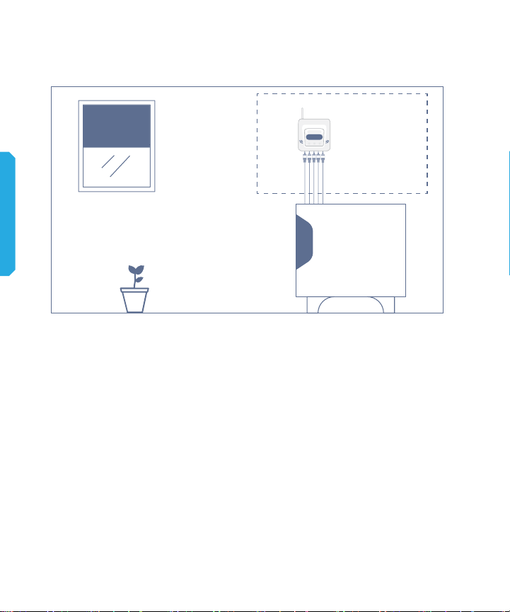
Before installation, it is important to determine the location of the
remote temperature monitoring device on the wall.
• Close to the fridge and to the power source.
• Where the device can safely sit on the wall without being hit by
the fridge door/ window
• Where the network connectivity is strong enough to ensure data
upload. NOTE: Turn device on to identify location where signal
strength is strongest.
• Easily accessible by a person to cycle through the temperatures
to get readings for each sensor
10
Page 11
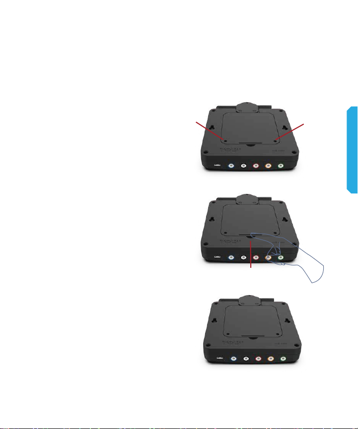
LOCATE AND REMOVE THE
BACK PANEL
1. Using the screwdriver with
your CT5, remove the screws
from the back panel. [1][2]
2. Squeeze small plastic tab with
the tip of your nger and lift the
back panel. [3]
3. Use care to gently and slowly
open the back panel because
battery is connected to the panel
and the wire connected to the
battery should not be pulled on
with force.
1
2
SETTING UP YOUR CT5
3
11
Page 12
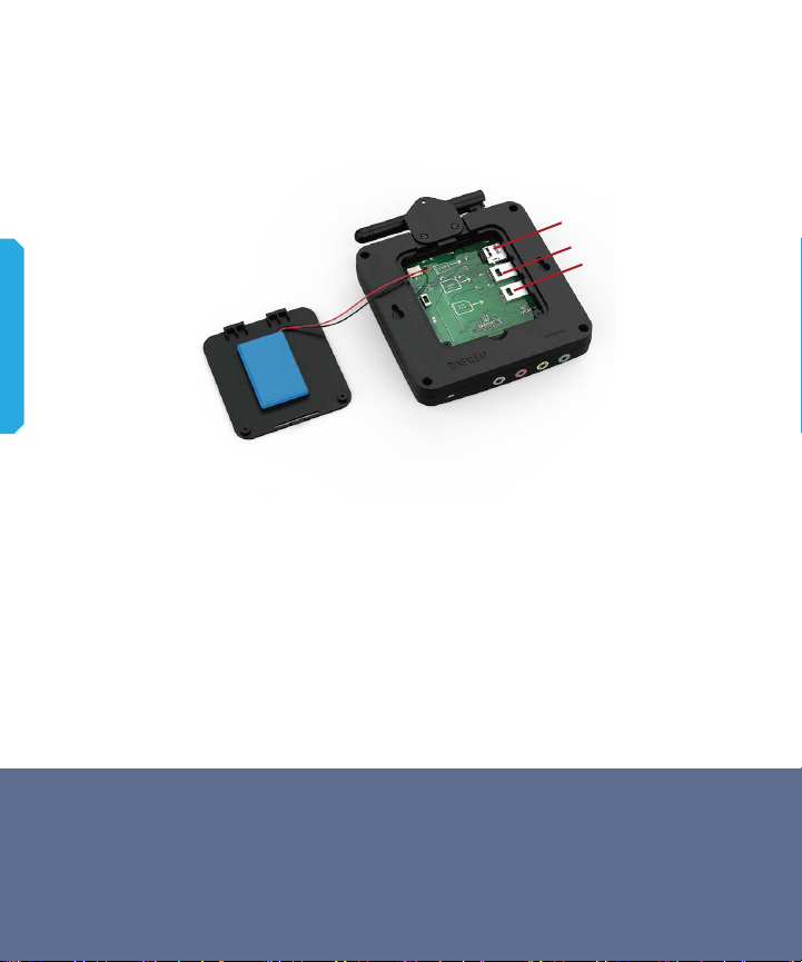
INSERT LOCAL SIM CARD
1
SETTING UP YOUR CT5
• Gently insert the SD card. You will hear a click. [1]
• Gently push SIM card into SIM 1 slot until you hear a click [2].
• Repeat for SIM 2 if using a second SIM. [3]
NOTE: CT5 only needs one SIM to function. The second SIM is
optional.
2
3
REMOVING SD AND SIM CARDS
Turn OFF device first. Gently press in the SD card or SIM card until it
clicks back slightly, then gently pull out the card.
12
Page 13
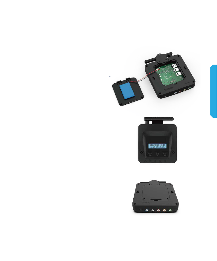
TURNING ON THE CT5
1. Flip the power switch up to ON.
2. Display screen should light up.
If screen is not lit up, ip power
switch o and on again.
3. Close the back panel by
tightening the screws using the
screwdriver provided.
SETTING UP YOUR CT5
13
Page 14
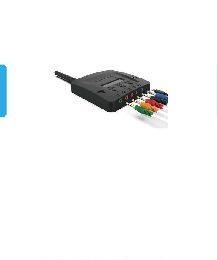
INSERT CORRESPONDING
SENSOR
SETTING UP YOUR CT5
Wait up to 10 minutes for sensors to start reading temperature to
show on display.
1. Find a location where signal strength is strong and close to the
fridge and the electrical outlet.
2. Once you nd a location, mount the CT5 to the wall through the
wall hanger using the provided screw and materials.
3. Connect the power adapter to the CT5 power port.
4. Connect CT5 power adapter to an electrical outlet, preferably to
the same source as the fridge.
5. Make sure the antenna is pointing up.
14
Page 15

TURNING ON THE CT5
15
Page 16
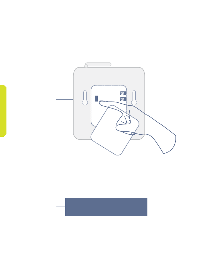
TURNING ON THE CT5
FLIP THE SWITCH UP TO
TURN ON CT5
DEVICE IS ON WHEN
TEMPERATURE IS SHOWN
16
2015/08/16 14:44
-15.4C 63% G1001
Page 17

UNDERSTANDING EACH
BUTTON
17
Page 18
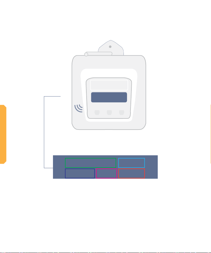
UNDERSTANDING EACH BUTTON
HOME SCREEN
STOP
CYCLE
ALARM
DISPLAY
FUNCTION
A B C D E
DATE TIME
2015/08/16 14:44
-15.4C 63% G100%
DEFAULT
POWER CONNECTIVITY
TEMP
The central “Home Screen” panel initially displays the “Date,” the
“Time,” the thermal data recorded for Sensor B “Default temp,” the
battery charge level “power,” signal strength to connect to the 2G
cellular network; internet connection signal.
18
Page 19
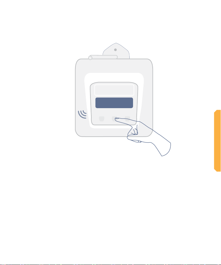
CYCLE DISPLAY
STOP
CYCLE
ALARM
DISPLAY
FUNCTION
A B C D E
Press the Cycle Display button to get temperature data of each
sensor including alarms, battery charge levels, and network signal
strength for each SIM.
Continuous pressing of the Cycle Display button will bring you
back to the home screen.
NOTE: If the display shows “transmitting,” “initializing,” “syncing,”
or “processing” the sensor is transmitting data to the server and
the display buttons to “Display Cycle” and the re-booting alarm
“Stop Alarm” are temporarily disabled. Please do not press the
buttons until the home screen is displayed again.
UNDERSTANDING EACH BUTTON
19
Page 20
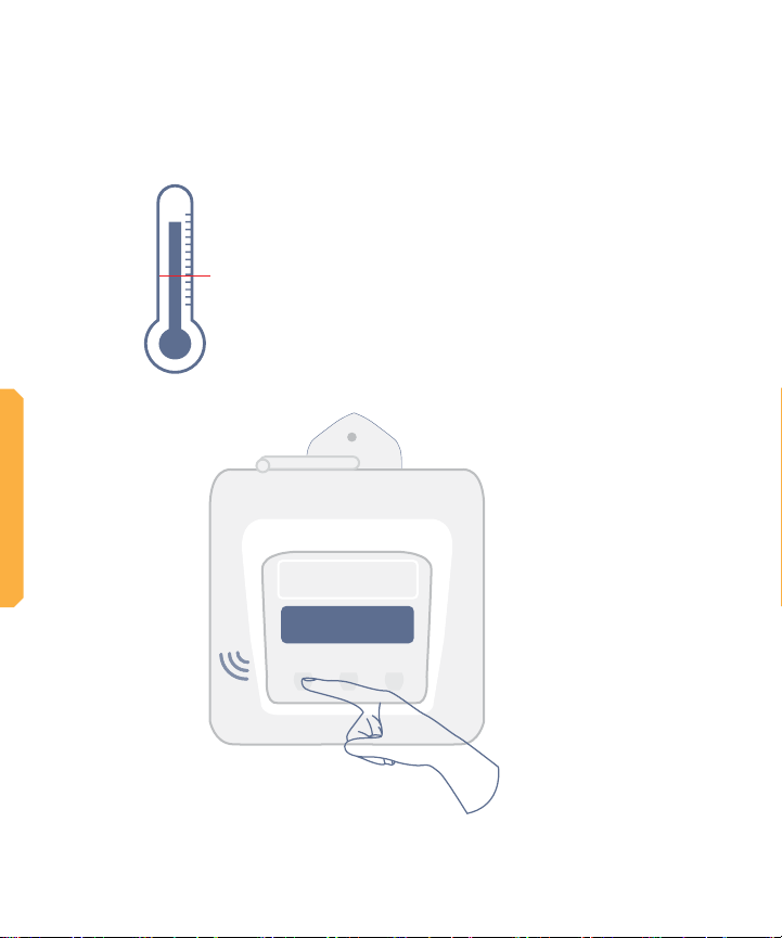
UNDERSTANDING EACH BUTTON
SAFE ZONE
ALARM BUTTON
The audio alarm on CT5 is congured to
buzz after the temperature is outside of
the pre-set range and duration (e.g. >8
°C for 10 hours or <-0.5 °C for 1 hour).
If the reason for alarm is not resolved,
the alarm will buzz every 6 hours.
STOP
CYCLE
ALARM
DISPLAY
FUNCTION
20
A B C D E
Press the Stop Alarm button to
mute the audio alarm.
Page 21

FUNCTION BUTTON
STOP
CYCLE
ALARM
DISPLAY
A B C D E
DO NOT press the Function button
FUNCTION
X
UNDERSTANDING EACH BUTTON
The Function button is for use by authorized technical repair
personnel only.
NOTE: The CT5 is programmed to take temperatures every 10
minutes. However, an authorized technician can use the “Function” button to force each sensor to sample the temperature
which takes about 1 minute.
21
Page 22

22
STOP
ALARM
CYCLE
DISPLAY
FUNCTION
A B C D E
RESETTING
Page 23
STOP
CYCLE
ALARM
DISPLAY
FUNCTION
A B C D E
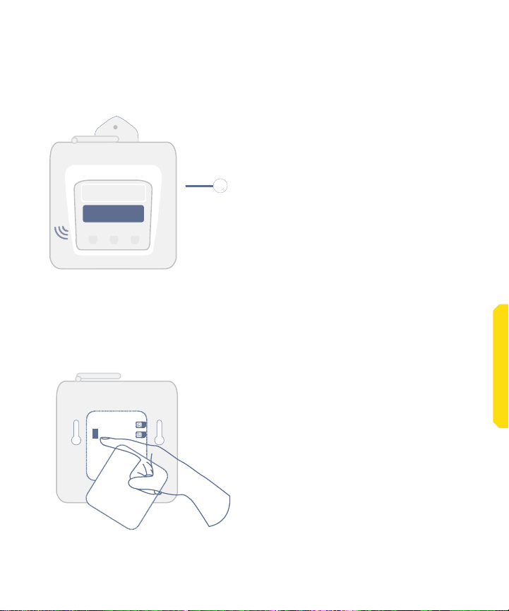
RESET THE CT5
RESET DEVICE OPTION 1
Use a pin to push the RESET
button on the side of the device
through a small hole
RESETTING
RESET DEVICE OPTION 2
Open the device and access the
power switch, to switch it OFF
and ON.
23
Page 24
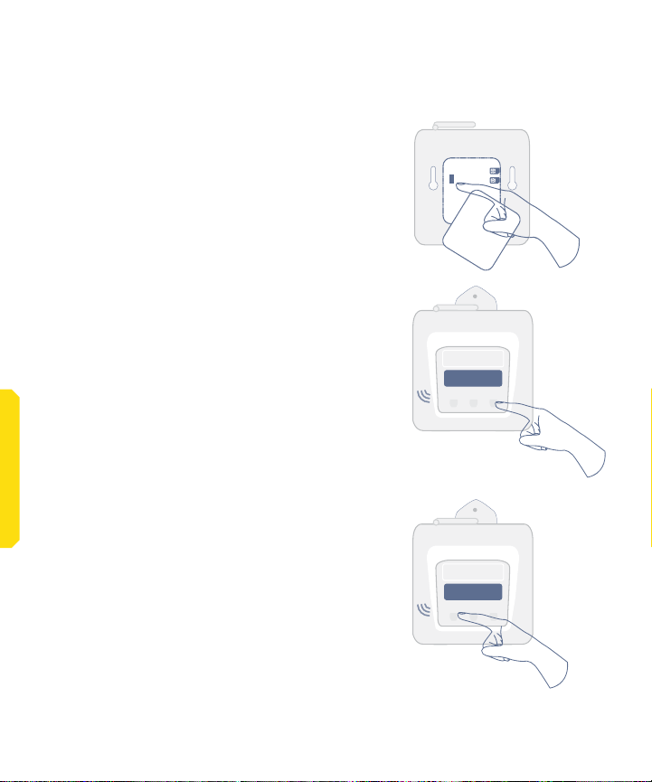
FACTORY RESET CT5
1. Open the back cover and switch OFF the
CT5.
2. Ensure the SD card and SIM card are
properly inserted into the device
3. Hold the Function button down while
switching ON the device.
4. Continue holding the Function button until
the display screen shows ‘Service Mode’
STOP
CYCLE
ALARM
DISPLAY
FUNCTION
5. Release Function button.
RRESETTING
6. CT5 will show ‘Buzzer test’. Press Stop
Alarm button. NOTE: By default the factory
conguration for the alarm buzzer is o, so the
alarm buzzer may not sound during this step.
7. RESET when normal screen is restored (as
shown in page 23).
8. NOTE: The factory reset will restore the
factory settings and clear all conguration
from the CT5, e.g. alarm settings, phone
numbers, etc. Use the ColdTrace dashboard
to re-update the settings.
24
A B C D E
STOP
CYCLE
ALARM
DISPLAY
FUNCTION
A B C D E
Page 25

BOOTING UP THE CT5
25
Page 26
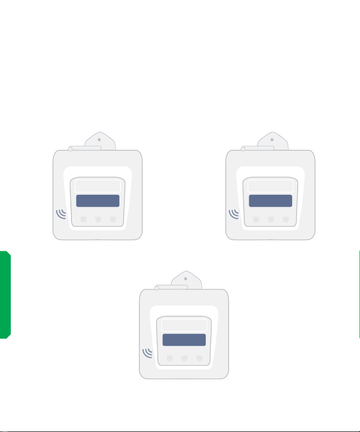
DISPLAY MESSAGES AND
WHAT THEY MEAN
The are a number of messages which show up on the screen during
normal operation of the CT5. Here we describe a few of them.
BOOTING UP THE CT5
26
SERVICE MODE
STOP
CYCLE
ALARM
DISPLAY
FUNCTION
A B C D E
BUZZER TEST
PRESS STOP ALARM
STOP
CYCLE
ALARM
DISPLAY
FUNCTION
A B C D E
LCD-INT
SUCCESSFUL
STOP
CYCLE
ALARM
DISPLAY
FUNCTION
A B C D E
Page 27
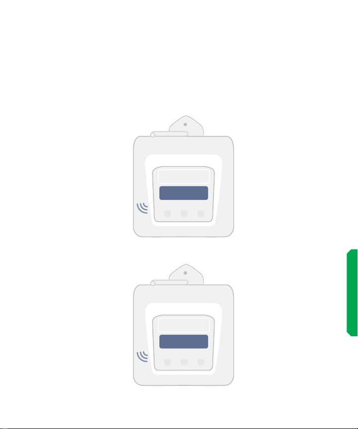
MESSAGES ON CT5
SCREEN
The device will show which SIM it is currently using to send data.
NOTE: May take 2 to 15 minutes to establish the initial connections
due to connectivity.
SIM 1
STOP
CYCLE
ALARM
DISPLAY
FUNCTION
A B C D E
BOOTING UP THE CT5
SIM 1 GPRS
ROAMING NET
STOP
CYCLE
ALARM
DISPLAY
FUNCTION
A B C D E
27
Page 28
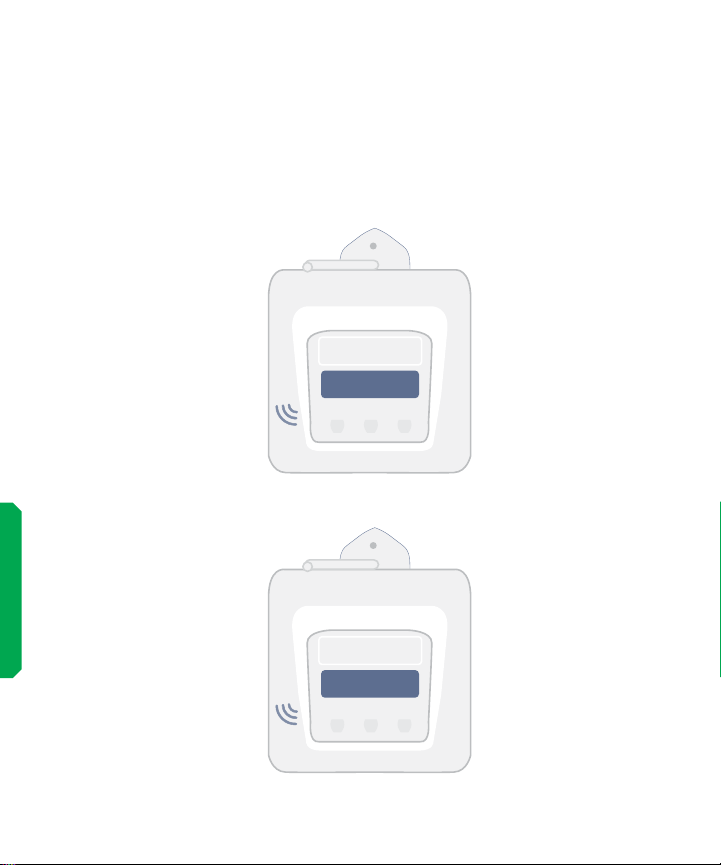
MESSAGES ON THE CT5
SCREEN
The device will show this text briey when checking if there are
any conguration SMS.
5 SMS FETCH
MSG PROCESSING
STOP
CYCLE
ALARM
DISPLAY
FUNCTION
A B C D E
BOOTING UP THE CT5
28
PARSING SMS...
CONFIGURING..*
STOP
CYCLE
ALARM
DISPLAY
FUNCTION
A B C D E
Page 29
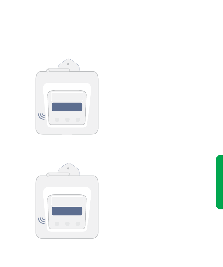
MESSAGES ON THE CT5
5 SMS FETCH
MSG PROCESSING
STOP
CYCLE
ALARM
DISPLAY
FUNCTION
A B C D E
PARSING SMS...
CONFIGURING..*
STOP
CYCLE
ALARM
DISPLAY
FUNCTION
SCREEN
CT5 is trying to upload the data.
The les getting uploaded are
dated and if the RTM is trying
to clear a backlog (les with an
earlier date) then this message
will remain on screen till it has
nished uploading. If the le is
current (today’s date) and the
signal quality is good, then it will
take only a few minutes.
CT5 has nished uploading the
data. This message remains on
the screen for a few seconds.
BOOTING UP THE CT5
A B C D E
29
Page 30

30
POST-INSTALLATION AND
TROUBLESHOOTING
Page 31
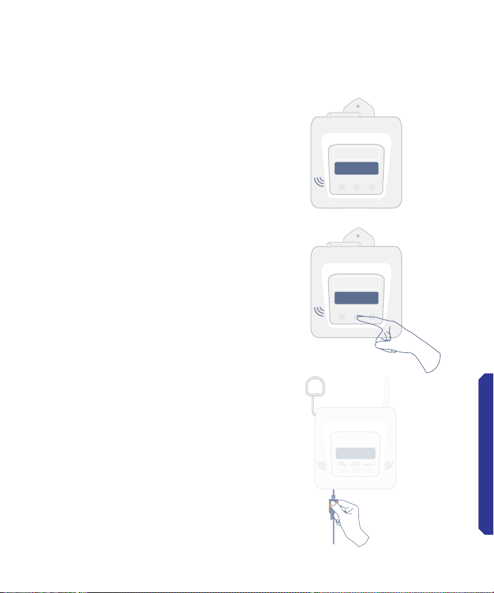
POST-INSTALLATION
STOP
ALARM
CYCLE
DISPLAY
FUNCTION
1. Check the display screen on
CT5 and make sure it shows a
normal reading.
2. Cycle display to make sure
there are no errors and all the
sensors can be read. If no reading
is showing yet, wait 10 minutes
after connecting the sensors.
NOTE: The last display screen will
show an error message, please
ignore.
3. Check all sensor cables are
plugged rmly into CT5.
2015/08/16 14:44
-15.4C 63% G1001
STOP
CYCLE
ALARM
DISPLAY
FUNCTION
A B C D E
2015/08/16 14:44
-15.4C 63% G1001
STOP
CYCLE
ALARM
DISPLAY
FUNCTION
A B C D E
4. Check the power adapter
is plugged rmly in the CT5
and the electrical outlet at the
other end (display should show
‘charging’).
A B C D E
POST-INSTALLATION / TROUBLESHOOTING
31
Page 32
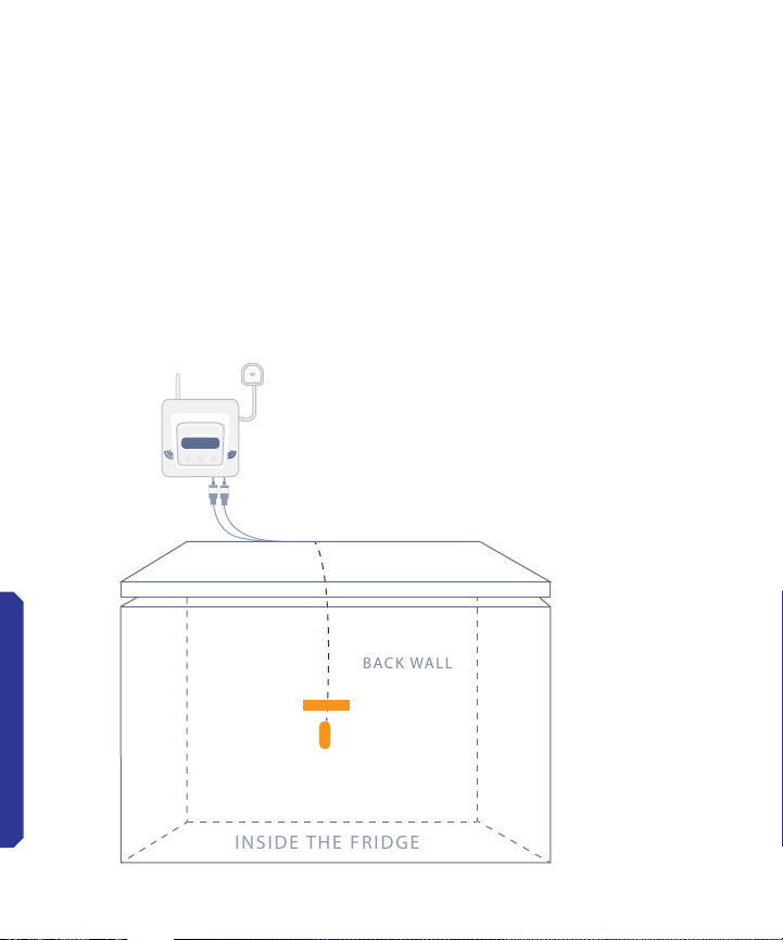
SENSOR PLACEMENT FOR CT5
INSIDE THE FRIDGE
BACK WALL
Any CT5 can control a maximum of 5 sensors placed in up to 5
refrigerators. The installation depends on the type of refrigerated
enclosure and thermal monitoring criteria. The diagram below
shows one of the sensors placed against the interior back wall
of the refrigerator with the provided fastener clip. The installation
of the sensor inside the refrigerator varies depending on the type
and model. Contact Nexleaf for more information.
NOTE: Use the clips provided with
the CT5 to attach the sensor inside
the refrigerator. Dry the interior wall of
the refrigerator with a paper towel to
facilitate the adhesion of the clips
CLIP
POST-INSTALLATION / TROUBLESHOOTING
STOP
CYCLE
ALARM
DISPLAY
FUNCTION
.
32
Page 33
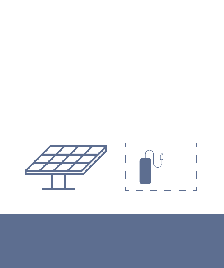
INSTALLING SOLAR KIT
• Solar installation requires an electrician as each installation is
dependent on the particular setup in each facility.
• CT5 can be supplied with a DC-to-DC convertor which can be
connected to a 12V solar panel.
• One end of the DC-to-DC converter is bare wires which are to be
attached to the 12V solar panel as the electrician sees t.
Accessories
2
1
1. Solar Power Kit
2. DC-to-DC Convertor
33
Page 34
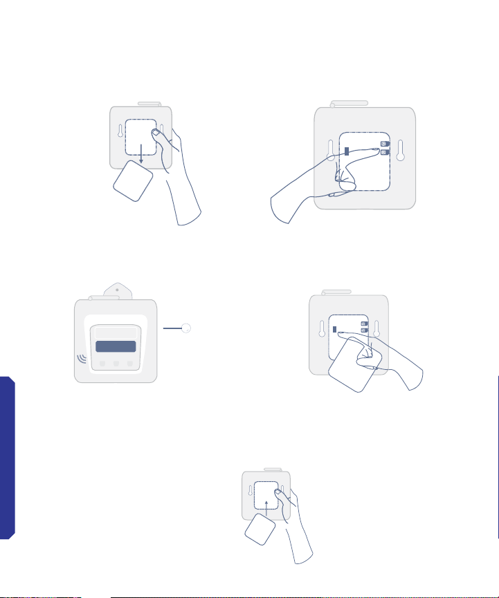
ADDING OR REPLACING
THE SIM CARD
Open the back cover of the
CT5 and switch it OFF.
STOP
CYCLE
ALARM
DISPLAY
FUNCTION
POST-INSTALLATION / TROUBLESHOOTING
A B C D E
RESET DEVICE OPTION 1
Use a pin to push for 2-3 seconds
the RESET button on the side of
the device through a small hole.
Close the back
panel and put the
2 screws.
34
Gently push the SIM card into
SIM 2 slot until you hear a click.
RESET DEVICE OPTION 2
Open the device and access the
power switch, to switch it OFF
and ON.
Page 35
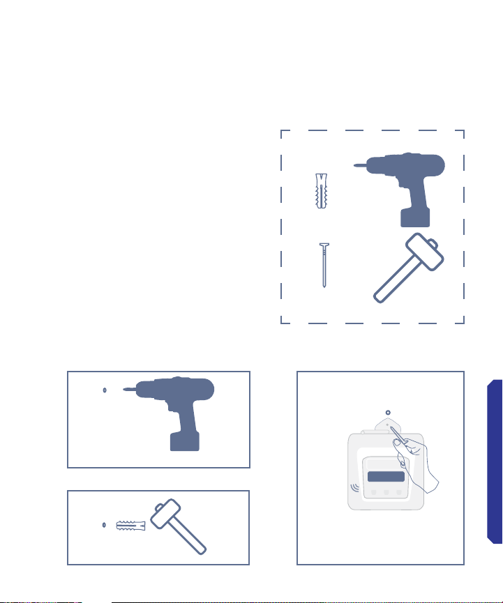
HOW TO MOUNT YOUR CT5
To hang the CT5 on the wall you
need the device, 1 wall anchor,
and 1 screw.
1. Drill a hole in the wall just
smaller than the wall anchor.
2. Hammer the wall anchor into
the hole.
3. Screw the CT5 to the wall an-
chor with the screw through the
installation hook.
1
2
Items Needed
x1
x1
3
STOP
CYCLE
ALARM
DISPLAY
FUNCTION
A B C D E
35
POST-INSTALLATION / TROUBLESHOOTING
Page 36
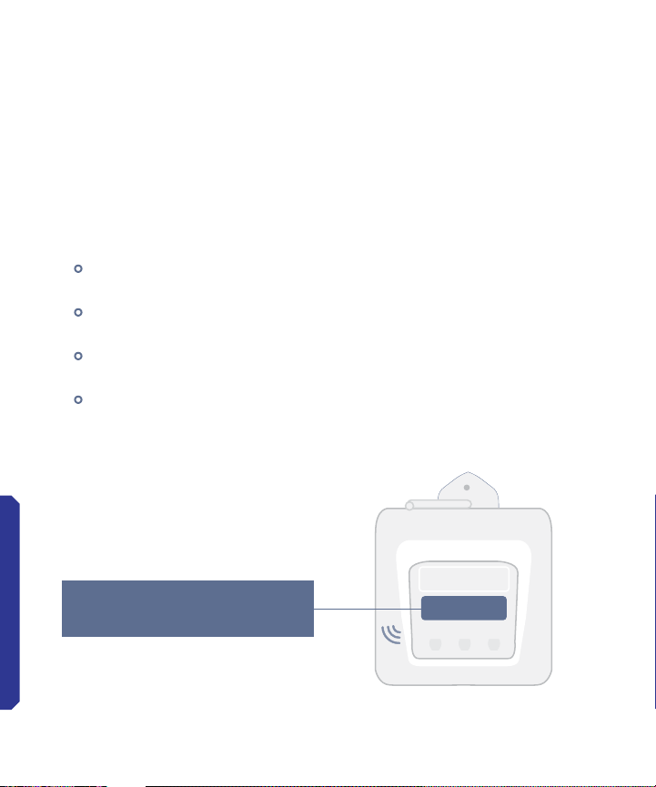
DATA IS NOT UPLOADED
ON DASHBOARD
PLEASE CHECK THE FOLLOWING:
• Display screen on the CT5
• Is there anything unusual? Please note down the error message
or take a picture of the screen with error.
• SIM connectivity level:
In the bottom right of the display screen, the number after ‘G’
shows connectivity level
If it shows 0%, ‘no signal’, ‘- -’, then it may mean the SIM is
either not active or there is no connectivity.
If the connectivity is below 20%, there may not be a good
enough signal to transmit the temperature data.
APN settings on the device may need to be changed. Contact
Nexleaf for updated les for the SD card.
POST-INSTALLATION / TROUBLESHOOTING
36
2015/08/16 14:44
-15.4C 63% G100%
2015/08/16 14:44
-15.4C 63% G1001
STOP
CYCLE
ALARM
DISPLAY
FUNCTION
A B C D E
Page 37

TROUBLESHOOTING
GENERAL TROUBLESHOOTING
While installing, if the CT5 doesn’t turn on, check the following:
• Make sure CT5 is securely connected to power adapter and
connected to wall-power to charge its battery.
• If connected to wall power and the device does not turn on, wait
15 minutes before trying again so the battery can charge. If the
device still did not turn on or is not functioning properly:
Check SD and SIM card(s) are correctly inserted.
Check the battery wires are connected and there is no damage
to the wires.
Verify power cable and adapter are securely plugged in.
Please contact technical support if the problem is not resolved
after trying the above steps.
CT5 BLANK SCREEN
A blank screen and no screen light is an indication of no power.
Follow these steps to make sure the CT5 is being charged:
• Power adapter is well connected to the device and the stabilizer
correctly.
• Check if extension board was used.
• Make sure the plug point is working. Plug in a phone charger or
any other electronic device into the plug point.
• Use any 5V smartphone micro USB mobile phone charger to
check.
37
Page 38

TROUBLESHOOTING
CONTINUED
UNUSUAL CT5 SCREEN
If the CT5 display shows ‘SD card error’ or a similar error message:
• Cycle through all the displays once using the middle button. This
may resolve the display issue.
• Reset the device. If problem persists after 2 hours, please report
the issue with the picture of the display screen.
NOTE: If the problem was with the power source and it has been
rectied, CT5 will require 10 minutes to recharge before it starts
working again.
38
CONTACT YOUR RTM DEPLOYMENT ADVISOR
OR NEXLEAF AT: [email protected]
Page 39

PRECAUTIONS AND
MAINTENANCE
GENERAL SAFETY PRECAUTIONS
• Do not place the device in extreme heat or near open ame as
these conditions can cause battery to explode.
• The CT5 temperature monitoring device needs to be secured on
the wall at all times.
• The CT5 should not be exposed to water.
• The back panel should be opened with care to protect the battery and wiring.
• The sensor cables should not be rubbing against any sharp
materials.
• As a best practice, CT5 should be connected to the voltage
stabilizer when the voltage stabilizer is available. NOTE: The
warranty will void if power adapter has failed as a result of volt-
age going outside of the 90V- 240V range.
CARE AND MAINTENANCE
• Warranty information – please read the user manual for details
on warranty carefully. Nexleaf oers limited warranty on all Remote Temperature Monitoring Data (not including power adapters or sensor cables).
• In case any spares are required, please contact the Nexleaf
representative.
39
Page 40

CORRECT DISPOSAL OF
THE PRODUCT
This marking on the product indicates that the product and its
electronic accessories (e.g. battery, power adapter) should not be
disposed of with other household or commercial waste at the end
of their working life.
Users should contact either Nexleaf, supplier, or their
local government oce for details on where and how they can
take these items for environmentally safe recycling. This product
is RoHS compliant and CE marked.
40
Page 41

WARRANTY
1. Limited Warranty. Nexleaf Analytics, in the event that your Product
was purchased directly from Nexleaf Analytics, or the Nexleaf Analytics
aliate, in the event your Product was purchased directly from such
aliate or such aliate supplied your Product to the authorized Nexleaf
reseller from which your Product was purchased (Nexleaf Analytics or
such aliate, “Nexleaf”) warrants that all Remote Temperature Monitoring Data Loggers (not including power adapters or sensor cables for the
Temperature Monitoring Data Loggers) (“Product”) to be free of manufac-
turing defects in materials and workmanship when properly installed and
operated for the warranty period as set forth below:
The warranty period shall be as indicated in your invoice at the time of
purchase of the Product (“Warranty Period”). Remedy for breach of this
Limited Warranty is limited to repair or replacement of the defective
Product. Any product which, under normal use and service, is proven
to breach the warranty contained herein within the periods noted above
will, upon examination by Nexleaf, and at its sole option, be repaired or
replaced by Nexleaf. Nexleaf will attempt to provide a response regarding
whether the warranty claim can be fullled within 30 business days upon
notication by the end-user of a warranty claim and receipt of Product at
the return location provided by Nexleaf Customer Service.
This Limited Warranty will not be breached, and Nexleaf will give no
credit for Products, including without limitation Products, which have
received normal wear and tear, been damaged (including by acts of
nature), tampered, abused, improperly re-installed by non-Nexleaf personnel or agents, missing parts or components, or repaired or altered by
others than authorized representatives of Nexleaf. This Limited Warranty
shall not apply to any Product that has failed due to or been damaged by
(a) accident, misuse, abuse, improper application, negligence, alteration, force majeure occurrence(s), transportation or handling after
installation, failure to operate products in accordance with manufacturer
41
Page 42

instructions, or failure to maintain the recommended operating, charging,
or storing environments in accordance with manufacturer instructions;
(b) unauthorized repair, maintenance, service, or modication of product
by the purchaser, end-user or a third party or attachment to or use of
non-Nexleaf supplied equipment; (c) use of non-Nexleaf supplied cleaning devices or supplies or consumables; or (d) the use of a non-standard
battery or sensor cables or a battery or sensor cables not recommended
by Nexleaf. Additionally, this Limited Warranty shall become null and void
with respect to any Product, sensor cable or battery thereof if any of the
following are encountered: (i) tampering with the Product; (ii) the SD Card
is missing or has been stolen; (iii) Product or any battery or any sensor
cables for such Product is missing or has been stolen; (iv) any Product
has been operated or used outside of pre-specied ranges, which will
be evidenced if ambient temperatures are recorded above 55 degrees
Celsius (either reported via ping or from on-site inspection indicating
temperature range has been violated) or the voltage goes outside of the
90V-240V range or the current goes outside of the 5 amp range of the
power adapter type; (v) the power adapter for any Product, which is rated
for 90V-240V as required, has failed, which will result from the operating
voltage going above or below the specied range; (vi) physical damage to
any Product, sensor cable or battery thereof, including without limitation,
cracks or breaks in the enclosure, broken or bent sensor connectors,
sensor ports, sensor cables or sensor probe, broken or bent antennae or
antennae connectors, missing screws, or bent or broken SIM Card or SD
Card slot, damage to the battery connector or battery cables, or physical
damage to the display, power switch or buttons; or (vii) water damage to
any Product. In addition, theft of any Product or any components thereof
or any peripherals/consumables thereto (including without limitation the
sensor cable, battery, SD card, power adapter) is not covered by this
Limited Warranty.
All other failures encountered during the warranty period set forth above
are considered to be a manufacturing defect and premature failure and
will be covered by this Limited Warranty.
42
Page 43

Limitations of Liability
The above-described warranty is expressly in lieu of all other warranties, express or implied, and all other warranties are hereby expressly
disclaimed, including without limitation the implied warranty of mer-
chantability and the implied warranty of tness for a particular purpose.
Nexleaf further disclaims all liability from personal injury relating to its
products to the extent permitted by law. By acceptance of any of Nex-
leaf’s products, the purchaser or end-user and its aliates and partners
assume all liability for the consequences arising from their use or mis-
use. No person, rm or corporation is authorized to assume for Nexleaf
any other liability in connection with the sale of its products. Furthermore, no person, rm or corporation is authorized to modify or waive
the terms of this paragraph, and the preceding paragraphs, unless done
in writing and signed by a duly authorized agent of Nexleaf. This war-
ranty gives you specic legal rights, and you may also have other rights
that vary from state to state.
NOTWITHSTANDING ANYTHING CONTAINED IN THIS LIMITED WARRANTY, IN NO EVENT SHALL NEXLEAF BE HELD LIABLE FOR ANY
CLAIMS, ACTIONS, DEMANDS, PENALTIES, LIABILITIES, COSTS,
CHARGES OR EXPENSES INCLUDING REASONABLE ATTORNEY FEES,
DAMAGES OR OTHER LOSSES, ARISING OUT OF BREACH OR FAILURE OF EXPRESS OR IMPLIED WARRANTY, BREACH OF CONTRACT,
MISREPRESENTATION, NEGLIGENCE, STRICT LIABILITY IN TORT,
FAILURE OF ANY REMEDY TO ACHIEVE ITS ESSENTIAL PURPOSE,
OR OTHERWISE, IN CONNECTION WITH THE DISSEMINATION, QUALITY, HANDLING, STOCKING, STORAGE OR ADMINISTRATION OF THE
MEDICINES, VACCINES OR OTHER HEALTH COMMODITIES PURSUANT
TO THE USE OF THE PRODUCT. THE DISSEMINATION, QUALITY, HANDLING, STOCKING, STORAGE OR ADMINISTRATION OF THE MEDICINES, VACCINES OR OTHER HEALTH COMMODITIES TO PATIENTS
SHALL, AT ALL TIMES, BE THE RESPONSIBILITY OF THE PURCHASER
OR END-USER ITS AGENCIES, HEALTH CENTRES, HEALTH FACILITIES,
OFFICERS, EMPLOYEES AND REPRESENTATIVES.
43
Page 44

TO THE MAXIMUM EXTENT PERMITTED BY LAW UNDER NO CIRCUMSTANCES SHALL NEXLEAF, INCLUDING ITS OFFICERS, DIRECTORS,
EMPLOYEES, AGENTS, CONTRACTORS, SUBCONTRACTORS, SUPPLIERS OR SOFTWARE DEVELOPERS, BE REPSONSIBLE OR LIABLE
FOR DIRECT, SPECIAL, INCIDENTAL OR CONSEQUENTIAL DAMAGES
RESULTING FROM ANY BREACH OF WARRANTY OR CONDITION, OR
UNDER ANY OTHER LEGAL THEORY, EVEN IF INFORMED OF THEIR
POSSIBILITY, INCLUDING BUT NOT LIMITED TO LOSS OF USE; LOSS OF
REVENUE, LOSS OF ACTUAL OR ANTICIPATED PROFITS OR BENEFITS
(INCLUDING LOSS OF PROFITS ON CONTRACTS); LOSS OF THE USE OF
MONEY; LOSS OF ANTICIPATED SAVINGS; LOSS OF BUSINESS; LOSS OF
OPPORTUNITY; LOSS OF GOODWILL; LOSS OF REPUTATION; LOSS OF,
DAMAGE TO, COMPROMISE OR CORRUPTION OF DATA; ANY INDIRECT
OR CCONSQUENTIAL LOSS OR DAMAGE HOWSOEVER CAUSE INCLUDING THE REPLACEMENT OF EQUIPMENT AND PROPERTY, ANY COSTS
OF RECOVERING, PROGRAMMING, OR REPRODUCING ANY PROGRAM
OR DATA STORED IN OR USED WITH THE PRODUCT OR ANY FAILURE
TO MAINTAIN THE CONFIDENTIALITY OF INFORMATION STORED IN OR
RECORDED BY THE PRODUCT; OR ANY INDIRECT, CONSEQUENTIAL,
SPECIAL, PUNITIVE, OR INCIDENTAL DAMAGES (INCLUDING, BUT NOT
LIMITED TO, LABOR AND ANALYSIS FEES), WHETHER FORESEEABLE
OR UNFORESEEABLE, BASED ON ANY CLAIM OF ANY OTHER PARTY
ARISING OUT OF BREACH OR FAILURE OF EXPRESS OR IMPLIED WARRANTY, BREACH OF CONTRACT, MISREPRESENTATION, NEGLIGENCE,
STRICT LIABILITY IN TORT, FAILURE OF ANY REMEDY TO ACHIEVE ITS
ESSENTIAL PURPOSE, OR OTHERWISE. NOTWITHSTANDING THE FORM
(E.G., CONTRACT, TORT OR OTHERWISE) IN WHICH ANY LEGAL OR
EQUITABLE ACTION MAY BE BROUGHT, IN NO EVENT WILL NEXLEAF BE
LIABLE FOR DAMAGES OR LOSSES THAT EXCEED, IN THE AGGREGATE,
THE AMOUNT PAID BY PURCHASER FOR THE PRODUCT.
NEXLEAF DISCLAIMS ANY REPRESENTATION THAT IT WILL BE ABLE
TO REPAIR ANY PRODUCT UNDER THIS WARRANTY OR REPLACE THE
PRODUCT WITHOUT RISK TO OR LOSS OF INFORMATION STORED ON
THE PRODUCT.
44
Page 45

2. Warranty Claim Process.
(a) To submit a warranty claim (“Warranty Claim”):
Contact Nexleaf Customer Service by email:
For all other Warranty Claims: [email protected]
When you submit a Warranty Claim, please include:
• Model number
• Date & Time of the reported problem
• Location (E.g. Province/District, State, Country)
• Reason for claim
• Request an identifying number associated with your Warranty Claim
(“Claim Number”).
• Name of person lling out the claim with contact and address information.
• Provide contact information for your assigned representative (the
“Purchaser Representative”) who is authorized to oversee the Warranty Claim and with whom Nexleaf Customer Service will communicate regarding the claim. In order to process Warranty Claims, the
customer must notify Nexleaf of the identity and method of contacting the Purchaser Representative.
(b) Returning Product to Nexleaf:
(i) Please make sure you have requested a Claim Number. Nexleaf will
process only Warranty Claims that have been assigned a Claim Number.
(c) Replacement Devices:
If the Warranty Claim is valid and your Product needs to be replaced,
Nexleaf will ship the replacement Product to the purchaser or its repre-
sentative. Unless otherwise specied, Nexleaf will not be responsible
for installing the new replacement Product. The Warranty Period will
remain based on the purchase date of the original Product and will not
be restarted as a result of the replacement Product. For services such as
installations or annual maintenance, please contact Nexleaf directly as
these are not covered under this Limited Warranty.
(d) Documents Required to Establish Warranty.
In order to process Warranty Claims and provide service, Nexleaf and
its service representative(s) will require access to data collected by the
Product that is the subject of the Warranty Claim either via access to
45
Page 46

the platform that is collecting and processing the data or via sharing of
the data les if Nexleaf’s servers are not being used. This information is
required and will only be used to analyze and troubleshoot the Product.
Nexleaf will coordinate with the Purchaser Representative to access this
information.
(e) General
Any information exchanged between us regarding this Limited Warranty
or a Warranty Claim is not condential or proprietary, including any infor-
mation you disclose over the phone or electronically.
Nexleaf and its aliates, subcontractors, resellers and distributors may
process, store and use information about your transaction and your contact information, including name, phone numbers, address, and e-mail
addresses, to process and fulll your transaction. We may also contact
you to notify you about any product recall, safety issue or service actions.
Where permissible under local law, we may use this information to inquire
about your satisfaction with our products or services or to provide you
with information about other products and services. You may decline to
receive any further such communications from us at any me. In accomplishing these purposes, we may transfer your information to any country
where we do business, we may provide it to entities acting on our behalf,
or we may disclose it where required by law.
If any provision of this Limited Warranty is deemed unenforceable or void,
the remaining provisions shall remain in eect.
Nothing in this Limited Warranty aects any statutory rights of consumers
that may not be waived or limited by contract.
No other license or rights (including license or rights under patents) are
granted by Nexleaf. Nexleaf does not grant you any the right to use its
trademarks, trade names, service marks, logos or other designations in
any promotion or publication without prior written consent.
This Limited Warranty may not be assigned by you, in whole or in part,
without the prior written consent of Nexleaf. Any attempt to do so is void.
Nexleaf may assign this Limited Warranty to an aliate or to a successor
organization in its sole discretion.
46
Page 47

CT5 SET UP AND OPERATIONS
GUIDE
47
 Loading...