


WVL2™
Installation and
Setup Manual

WVL2™ Installation and Setup Manual
IDSC Holdings LLC retains all ownership rights to the Wireless Vehicle Link 2 (WVL2) and its documentation. The
WVL2 source code is a confidential trade secret of IDSC Holdings LLC. You may not decipher or decompile WVL2,
develop source code for WVL2, or knowingly allow others to do so. The WVL2 and its documentation may not be
sublicensed or transferred without the prior written consent of IDSC Holdings LLC.
This manual, as well as the software it describes, is furnished under license and may only be used or copied in
accordance with the terms of such license. The content of this manual is furnished for informational use only, is
subject to change without notice, and should not be construed as a commitment by IDSC Holdings LLC. IDSC
Holdings LLC assumes no responsibility or liability for any errors or inaccuracies that may appear in this book.
Except as permitted by such license, no part of this publication may be reproduced, or transmitted, in any form or by
any means, electronic, mechanical, or otherwise, without the prior written permission of IDSC Holdings LLC.
Windows is a registered trademark of the Microsoft Corporation. All other trademarks mentioned herein are the
property of their respective owners.
NEXIQ Technologies is a trademark of IDSC Holdings LLC.
2010 IDSC Holdings LLC. All Rights Reserved.
www.nexiq.com
Part No. 1400-381 Revised 12/06/2011

Chapter 1:
Introducing the Wireless Vehicle Link 2 ....................1
WVL2 Components .......................................................................2
Component Checklist ...........................................................................3
Product Specifications ...................................................................4
System Requirements ...................................................................5
WVL2 Device .................................................................................6
Chapter 2:
Setting Up Wireless Communication ........................9
Installation Process Flowchart (Wireless) ....................................10
Outline of Installation and Setup Process ....................................11
Step 1: Install the WVL2 Drivers and Utilities ..............................12
Step 2: Configure the Wireless Network Card .............................22
Windows XP (Service Pack 2/3) .........................................................23
Windows 7 ................ ... ... .... ... ....................................... ... ... ... .... ... ... ...33
Step 3: Connect to a Vehicle .......................................................45
Chapter 3:
Setting Up Wired Communication .........................47
Overview ......................................................................................48
Installation Process Flowchart (Wired) ........................................49
Setting Up the WVL2 for Wired Communication .........................50
WVL2™ Installation and Setup Manual ii

Chapter 4:
The WVL2 Explorer ..............................................55
Overview: Using the WVL2 Explorer ...........................................56
Configuration ...................................................................................... 57
Firmware ............................................................................................59
The File Menu .............................................................................62
The Tools Menu ..........................................................................63
Ping .................................................................................................... 63
Options ............................................................................................... 65
Application Feature .........................................................................65
Connection Manager Feature ............................................ .... ... ... ...66
Discovery Feature ...........................................................................69
The Help Menu ............................................................................71
Chapter 5:
WVL2 Troubleshooting Information .......................73
LED Issues ..................................................................................74
Configuration Issues ....................................................................75
Wireless Communication Issues .................................................76
Vehicle Application Issues ...........................................................78
Appendix A:
Setting Up a Second WVL2 ...................................79
Overview .....................................................................................80
Setting Up a Second WVL2 .........................................................81
Two Conditions to Watch For ......................................................85
Firmware Conflict ...............................................................................85
IP Address Conflict ................... ... .... ... ... ... .... ... ...................................87
iii WVL2™ Installation and Setup Manual

Introducing the
Wireless V ehicle Link 2
WVL2 Components, page 2
Product Specifications, page 4
System Requirements, page 5
WVL2 Device, page 6
1
The wireless Vehicle Link 2 (WVL2) is a hardware device that enables your PC/laptop
to retrieve vehicle information wirelessly via the 802.11 b/ g specification. Once configured ,
the WVL2 interfaces with your PC, enabling you to use specific PC appli cations to perform
vehicle diagnostics.
This chapter introduces the WVL2 and provides details regarding the communication
modes available to you to interface with your PC/laptop.
WVL2™ Installation and Setup Manual 1
Chapter 1 • Introducing the Wireless Vehicle Link 2
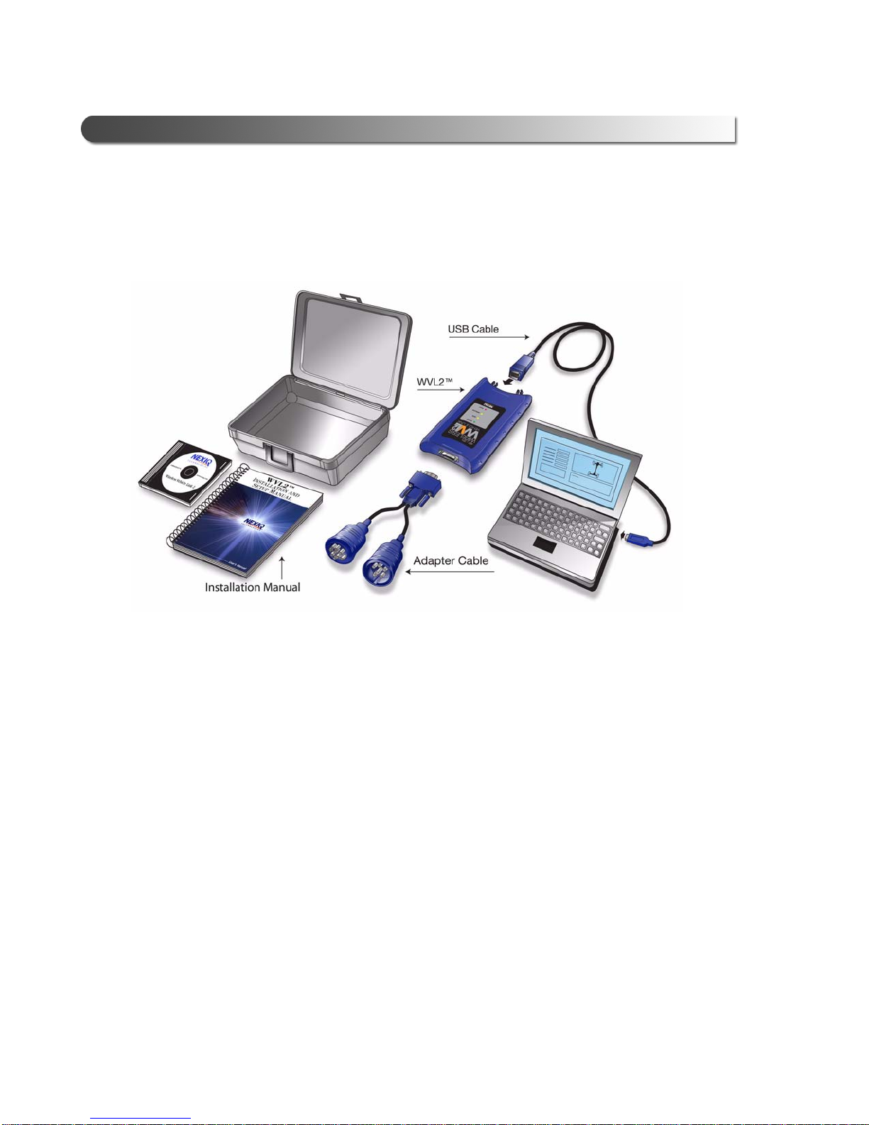
WVL2 Components
The following illustration details the WVL2 components:
Figure 1.1 WVL2 Components
2 WVL2™ Installation and Setup Manual

Component Checklist
The following components are included with your WVL2 kit. Be sure you have all
the items before installing and setting up the WVL2 on your PC/laptop.
Carrying Case
Wireless Vehicle Link 2 (WVL2)
WVL2 Drivers and Utilities Installation CD
6 & 9-pin Deutsch Y Cable (PN 405048)
15 ft. USB Cable
WVL2 Installation and Setup Manual
Adapter Guide for the WVL2
- WVL2 Components
WVL2™ Installation and Setup Manual 3

Chapter 1 • Introducing the Wireless Vehicle Link 2
Product Specifications
The WVL2 is configured with the following specifications:
Feature Data
Physical Dimensions 1.25” H x 4.0” W x 6.75” L
Weight .42 lb. (0.19 kg)
Power Requirements 6.5 to 32 VDC, 5 Watts Max
Operating Temperature
Vehicle Protocols Supported • ALDL (9600-baud syste ms)
(32 mm x 102 mm x 171 mm)
0
to 70C (32 to 158F)
• J1708/J1587
• J1939/J228 4 CAN
• J1850 (VPW and PWM)
• ISO 9141
• KWP2000
• ISO-15765
•ATEC 1
Wireless Communication TCP/IP over 802.11 b/g
Wired Communication USB
PC Drivers TMC RP1210A compliant
TMC RP1210B compliant
J2534
Vehicle Connector DB15F
4 WVL2™ Installation and Setup Manual

System Requirements
NOTE:
Be aware of the following system requirements:
Component Requirement
IBM PC Compatible Computer • Pentium M 4 1.7GHz pr oc es so r
Operating System
- System Requirements
• RAM: 512MB
• 300 MB available hard drive
storage space
• Internal wireless network card, or
wireless network slot available
• CD drive
• USB port
• 1024 x 768 screen resolution and
a display setting of “normal” size
(96 dpi)
Windows
®
:
• XP (Service Pack 2/3)
• Windows 7
i If your PC/laptop does not have an internal wireless network card, you will
need to purchase an external wireless network card.
WVL2™ Installation and Setup Manual 5

Chapter 1 • Introducing the Wireless Vehicle Link 2
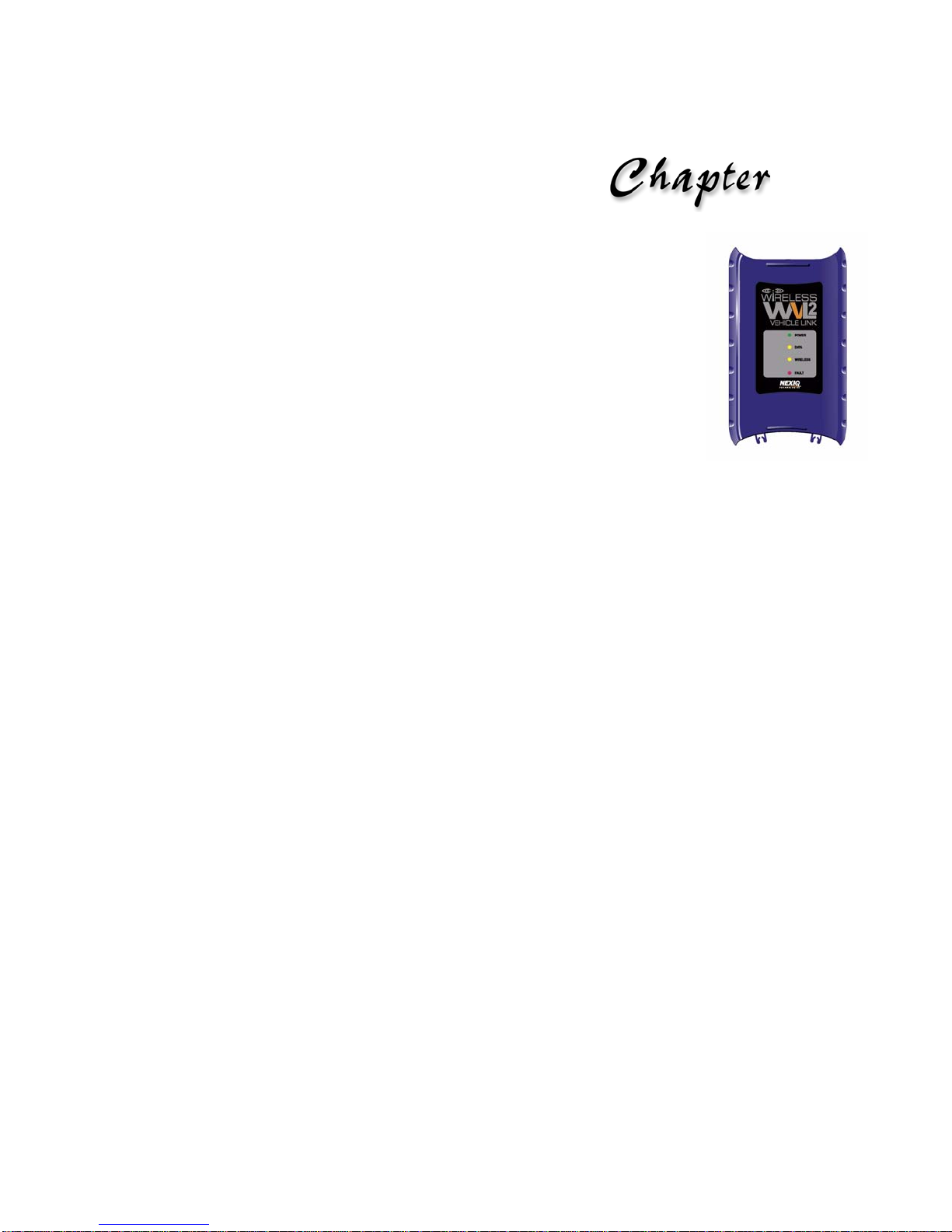
WVL2 Device
The following illustration details the features of the WVL2 diagnostic device:
Figure 1.2 Wireless Vehicle Link 2 (WVL2)
Legend
A—Vehicle Port
Connects the WVL2 to a vehicle.
B—Power LED
Lights up green when the WVL2 receives power.
6 WVL2™ Installation and Setup Manual

- WVL2 Device
NOTE:
C—Data LED
Lights up yellow when the WVL2 receives data from the vehicle.
D—Wireless LED
Blinks yellow whenever the WVL2 is connected wirelessly. The LED blinks
faster for a strong connection, and slower for a weak connection.
E—Fault LED
Lights up red when a problem is detected.
With a wireless connection, the Fault LED and the Wireless LED work together
in the following way:
LED Behavior Fault Condition
Both LEDs off No access point or other ad hoc card
found
Both LEDs blinking at a one
second rate
Both LEDs blinking alternately at a
one second rate.
F—USB Port
Connects the WVL2 to your PC/laptop.
No SSID found
No IP address found
i For additional information on trouble shooting LED behavior, refer to
Chapter 5: WVL2 Troubleshooting Information, later in this manual.
WVL2™ Installation and Setup Manual 7

Setting Up Wireless
Communication
Installation Process Flowchart (Wireless), page 10
Outline of Installation and Setup Process, page 11
Step 1: Install the WVL2 Drivers and Utilities, page 12
Step 2: Configure the Wireless Network Card, page 22
Windows XP (Service Pack 2/3), page 23
Windows 7, page 33
Step 3: Connect to a Vehicle, page 45
2
This chapter provides information you need to get started, including instructions on
installing all necessary software files.
Wireless Vehicle Link 2 Installation and Setup Manual
9

Chapter 2 • Setting Up Wireless Communication
Install the WVL2
Drivers and
Utilities
Install an External
Wireless Network
Card
NO
Internal
Wireless
Network Card
Available?
YES
Operating
System?
Configure the
Wireless Network
Card
for Windows 7
Configure the
Wireless Network
Card
for Windows XP
XPWindows 7
Connect WVL2 to
Vehicle
Connect WVL2 to
Vehicle
Installation Process Flowchart (Wireless)
Figure 2.1 Wireless Installation Process Flowchart
10
Wireless Vehicle Link 2 Installation and Setup Manual

- Outline of Installation and Setup Process
NOTE:
Outline of Installation and Setup Process
Step 1: Install the WVL2 Drivers and Utilities.
Step 2: Configure the Wireless Network Card and setup a peer-to-peer (ad
hoc) network to connect to the WVL2.
Depending on your operating system, choose one of the following:
• Windows® XP (Service Pack 2/3)
• Windows® 7
Step 3: Connect the WVL2 to a Vehicle.
i For assistance in setting up encryption, please contact Customer Support
at 1-800-639-6774.
Wireless Vehicle Link 2 Installation and Setup Manual
11

Chapter 2 • Setting Up Wireless Communication
NOTE:
IMPORTANT:
Step 1: Install the WVL2 Drivers and Utilities
This section provides instructions for installing the WVL2 drivers and utilities.
i If you have previously installed a WVL2, you must close the WVL2
Explorer. Right-click on the WVL2 icon in your laptop’s system tray and
select “Exit WVL2 Explorer.”
To install the WVL2 drivers and utilities:
1 Close any programs that are currently running, and place the WVL2 Drivers
& Utilities CD in your PC’s CD/DVD-ROM drive.
ä If your network has a firewall (i.e., a system designed to prevent unautho-
rized access to or from a private network), contact your local IT manager
and request that he or she assist you in opening Port 9294 UDP.
If you are not sure if you have a firewall installed, contact you r loca l IT
manager prior to installing this product.
If you do not have a firewall installed, you don’t need to do anything.
12
Wireless Vehicle Link 2 Installation and Setup Manual

- Step 1: Install the WVL2 Drivers and Utilities
WARNING:
The WVL2 Drivers Setup Wizard Welcome screen is displayed.
Figure 2.2 Setup Wizard Welcome Screen
ä You must disconnect all RP1210A adapters prior to proceeding with the
installation.
Wireless Vehicle Link 2 Installation and Setup Manual
13

Chapter 2 • Setting Up Wireless Communication
2 Click Next.
Figure 2.3 WVL2 License Agreement
3 Read the information displayed on the License Agreement screen (using
the scroll bar to view the entire display).
4 Click the I Agree radio button.
5 Click Next.
14
Wireless Vehicle Link 2 Installation and Setup Manual

- Step 1: Install the WVL2 Drivers and Utilities
NOTE:
The Select Installation Folder screen is displayed, indicating the location
where the drivers will be installed.
Figure 2.4 Select Installation Folder
i If you want to install the drivers in a location other than the default, click
the Browse button. The default is recommended.
You can also view available disk space and compare that to the space
required for the drivers, by clicking the Disk Cost button.
6 To accept the default location, click Next.
Wireless Vehicle Link 2 Installation and Setup Manual
15

Chapter 2 • Setting Up Wireless Communication
The Confirm Installation screen is displayed.
Figure 2.5 Confirm Installation
7 Click Next to continue.
16
Wireless Vehicle Link 2 Installation and Setup Manual

The installation process continues.
- Step 1: Install the WVL2 Drivers and Utilities
Figure 2.6 Installing WVL2 Drivers
This may take a few seconds; a status bar keeps you informed of installatio n
progress.
Wireless Vehicle Link 2 Installation and Setup Manual
17

Chapter 2 • Setting Up Wireless Communication
If you are running Windows 7, the following screen may appear.
Figure 2.7 Windows Security Screen
If the Windows Security screen appears, select Install this driver software
anyway. Then click Next.
18
Wireless Vehicle Link 2 Installation and Setup Manual

- Step 1: Install the WVL2 Drivers and Utilities
The Installation Complete screen is displayed.
Figure 2.8 Installation Complete
8 Click Close.
The WVL2 Drivers Setup Wizard closes and the following dialog box opens.
Figure 2.9 Restart Message
9 Click Yes.
Wireless Vehicle Link 2 Installation and Setup Manual
19

Chapter 2 • Setting Up Wireless Communication
The following Windows Security Alert may appear.
Figure 2.10 Windows Security Alert
If the Windows Security Alert appears, click Unblock.
20
Wireless Vehicle Link 2 Installation and Setup Manual

- Step 1: Install the WVL2 Drivers and Utilities
If you are running Windows 7, the following screen may appear:
Figure 2.11 Windows 7 Security Alert
Make sure both check boxes are checked, and click Allow Access.
10 Remove the WVL2 Drivers & Utilities CD from your CD-ROM drive.
11 Move on to Step 2: Configure the Wireless Network Card, next in this
manual.
Wireless Vehicle Link 2 Installation and Setup Manual
21

Chapter 2 • Setting Up Wireless Communication
NOTE:
NOTE:
NOTE:
Step 2: Configure the Wireless Network Card
This section provides instructions for configuring the wireless network card (internal or external) for Windows XP (Service Pack 2/3) and Windows 7. It also g uides
you through setting up a network in ad hoc mode (peer-to-peer) to connect to the
WVL2.
i To set up a network in infrastructure mode, contact your local IT admin-
istrator. Due to numerous configuration variables involved in infrastructur e
mode, our Customer Support specialists cannot assist you in this
endeavor.
Please refer to the instructions appropriate for your system.
• Windows XP (Service Pack 2/3) (see page 23)
• Windows 7 (see page 33)
i The wireless network card you use to connect to th e WVL 2 shou l d be
reserved for that purpose only. Other wireless network cards/adapters can
be used to connect to the Internet and/or your local network.
i For assistance in setting up encryption, please contact Customer Support
at 1-800-639-6774.
22
Wireless Vehicle Link 2 Installation and Setup Manual

- Step 2: Configure the Wireless Network Card
NOTE:
Windows XP (Service Pack 2/3)
If your PC is running Windows XP (Service Pack 2/3), use the instructions below
to set up a peer-to-peer (ad hoc) network to connect to the WVL2.
To configure the wireless network card for Windows XP:
1 Navigate to your PC’s desktop.
2 Locate the Start button (found in the lower left corner of the display).
3 Click Start.
Figure 2.12 Opening network and Internet connections
4 Click Connect To.
i If your Windows
4
Connections
toolbar is set to “Classic,” select Start 4Settings
Wireless Vehicle Link 2 Installation and Setup Manual
23

Chapter 2 • Setting Up Wireless Communication
NOTE:
5 Click Show all connections.
Figure 2.13 Network Connections
6 Right-click on the Wireless Connection you plan on using for this network.
i If there is more than one wireless network, be sure to select the card that
you plan to use for this network.
7 Click Properties.
24
Wireless Vehicle Link 2 Installation and Setup Manual

- Step 2: Configure the Wireless Network Card
The Wireless Network Connection Properties page is displayed.
Figure 2.14 Wireless Network Connection Properties
8 Under Connect Using: (at the top of the screen), be sure that the card you
plan on using is showing.
9 Scroll to and select Internet Protocol (TCP/IP).
10 Click Properties.
Wireless Vehicle Link 2 Installation and Setup Manual
25

Chapter 2 • Setting Up Wireless Communication
NOTE:
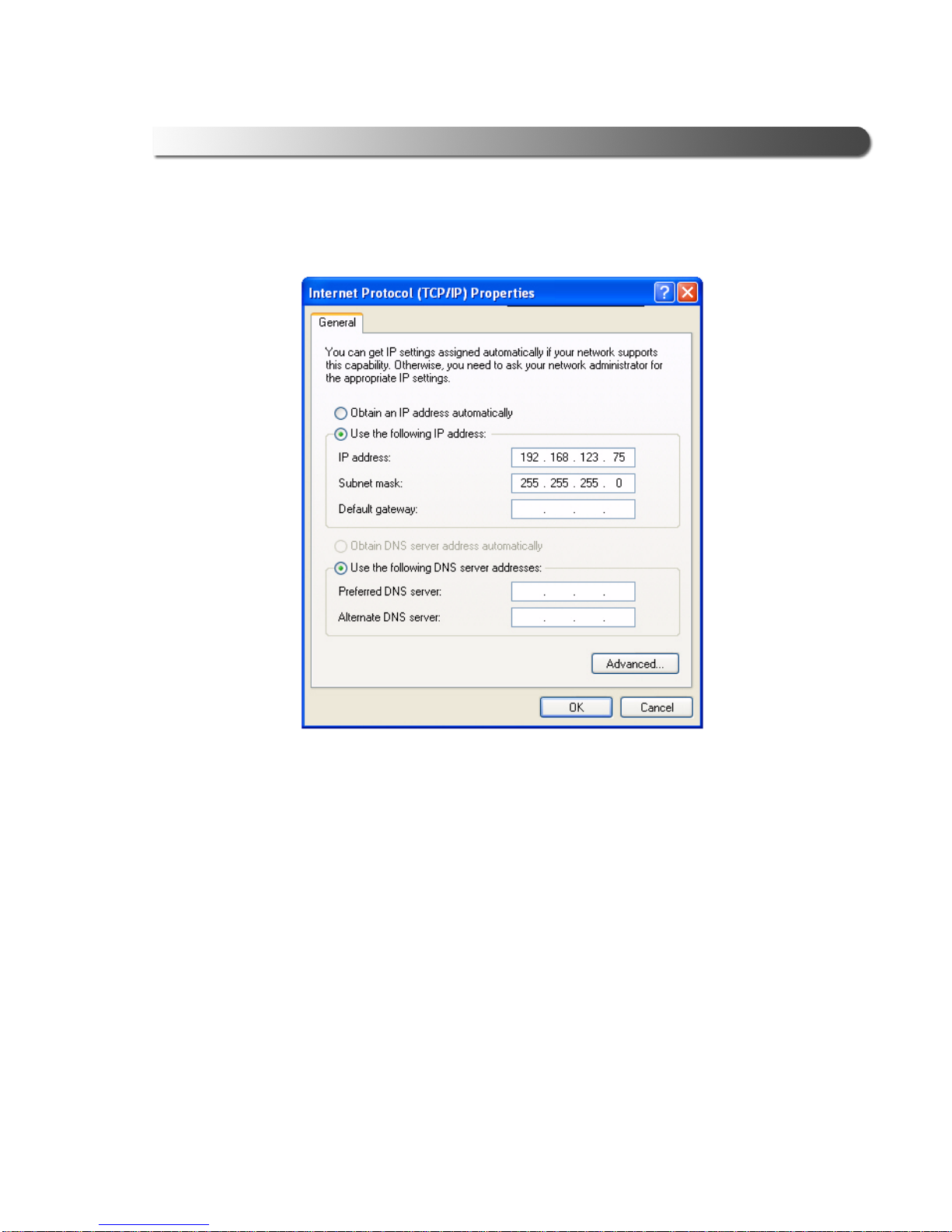
The Internet Protocol Properties page is displayed.
Figure 2.15 Internet Protocol (TCP/IP) Properties
11 Click Use the following IP address.
12 In the IP Address box, type the first three segments of the IP address, as
follows: 192.168.123
13 Type the last segment of the IP address, using a value between 1 and 100.
For example, a properly configured IP address reads: 192.168.123.75
i If setting up multiple PCs, be sure that each PC has a different number in
the last segment of the IP address. For example: PC 1 = 192.168.123.75
PC 2 = 192.168.123.76
26
Wireless Vehicle Link 2 Installation and Setup Manual
- Step 2: Configure the Wireless Network Card
14 Click inside the Subnet mask: field. The field should be automatically popu-
lated with a value (see the following sample screen).
Figure 2.16 Sample Internet Protocol (TCP/IP) Properties screen
15 If a value does not automatically appear, type a Subnet mask of
255.255.255.0
16 Click OK.
17 On the Wireless Network Connection Properties screen, click the
Wireless Networks tab.
Wireless Vehicle Link 2 Installation and Setup Manual
27

Chapter 2 • Setting Up Wireless Communication
The Wireless Networks tab is displayed.
Figure 2.17 Wireless Networks tab
18 Verify that the Use Windows to configure my wireless network settings
check box is checked.
19 Click Add.
28
Wireless Vehicle Link 2 Installation and Setup Manual

- Step 2: Configure the Wireless Network Card
NOTE:
If you are running Service Pack 3, the following screen is displayed.
Figure 2.18 Wireless network properties
Place a check mark in the Connect even if that network is not broadcasting box.
i The SSID box is case-sensitive, so you must use all capital letters.
20 Type WVL2_A in the Network name (SSID) text box.
21 Be sure that Network Authentication is set to Open.
22 Be sure that Data encryption is set to disabled.
Wireless Vehicle Link 2 Installation and Setup Manual
29

Chapter 2 • Setting Up Wireless Communication
23 Select This is a computer-to-computer (ad hoc) network ().
Figure 2.19 WVL2_A properties
24 Click OK.
The following message is displayed:
Figure 2.20 Disabled Encryption message
25 Click Continue Anyway.
30
Wireless Vehicle Link 2 Installation and Setup Manual

- Step 2: Configure the Wireless Network Card
NOTE:
The Wireless Connection Properties pa ge is displayed.
Figure 2.21 Wireless Network Connection Properties
26 Click the Advanced button.
i Make sure that you click on the Advanced button, not the Advanced tab.
Wireless Vehicle Link 2 Installation and Setup Manual
31

Chapter 2 • Setting Up Wireless Communication
The Advanced options screen is displayed:
Figure 2.22 Advanced options
27 Select the Computer-to-computer [ad hoc] networks only option ().
28 Be sure that the Automatically connect to non-preferred networks check
box is not selected; if it is selected, click the box to de-select it (
29 Click Close.
30 Click Close to close the Wireless Network Connection Pro perties screen.
31 Proceed to “Step 3: Connect to a Vehicle”, on page 45 of this manual.
).
32
Wireless Vehicle Link 2 Installation and Setup Manual

- Step 2: Configure the Wireless Network Card
NOTE:
IMPORTANT:
NOTE:
Windows 7
If your PC is running Windows 7, use the following instructions to set up a peerto-peer (ad hoc) network to connect to the WVL2.
i Use these instructions only if you are running Windows 7.
ä Prior to following these instructions, you must be connected to the vehi-
cle (see Step 3: Connect to a Vehicle, page 45). The WVL2 must be within
100 ft. of the vehicle to be in range.
i With Windows 7, each time you want to connect to the WVL2 you have to
click on the Network Connection Icon in the system tray of your PC’s
desktop (Figure 2.32, page 41).
To configure the wireless network card for Windows 7:
1 Navigate to your PC’s desktop.
2 Locate the Windows St art Icon (found in the lower left corner of the display).
Figure 2.23 Windows Start Icon
3 Click on the icon.
Wireless Vehicle Link 2 Installation and Setup Manual
33

Chapter 2 • Setting Up Wireless Communication
The Start Menu is displayed.
Figure 2.24 Start Menu
4 Select Control Panel.
34
Wireless Vehicle Link 2 Installation and Setup Manual

The Control Panel is displayed.
- Step 2: Configure the Wireless Network Card
Figure 2.25 Control Panel
5 Click View network status and tasks.
Wireless Vehicle Link 2 Installation and Setup Manual
35

Chapter 2 • Setting Up Wireless Communication
The Network and Sharing Center screen is displayed.
Figure 2.26 Network and Sharing Center Screen
6 From the panel on the left, click Change adapter settings.
36
Wireless Vehicle Link 2 Installation and Setup Manual

- Step 2: Configure the Wireless Network Card
NOTE:
The Network Connections screen is displayed.
Figure 2.27 Network Connections Screen
7 Right-click Wireless Network Connection.
i If there is more than one wireless network, be sure to select the card that
you plan to use for this network.
Wireless Vehicle Link 2 Installation and Setup Manual
37

Chapter 2 • Setting Up Wireless Communication
A drop-down menu is displayed.
Figure 2.28 Drop-down Menu
8 Select Properties.
38
Wireless Vehicle Link 2 Installation and Setup Manual

- Step 2: Configure the Wireless Network Card
The Wireless Network Connection Properties screen is displayed.
Figure 2.29 Wireless Network Connection Properties
9 Double-click on Internet Protocol Version 4 (TCP/IPv4).
Wireless Vehicle Link 2 Installation and Setup Manual
39

Chapter 2 • Setting Up Wireless Communication
NOTE:
The Internet Protoco l V ersio n 4 (TC/IPv4) Properties screen is displayed.
Figure 2.30 Internet Protocol Version 4 (TCP/IPv4) Properties
10 If it is not already selected, click the radio button next to Use the following
IP address.
11 In the IP Address box, type the first three segments of the IP address, as
follows: 192.168.123
12 Type the last segment of the IP address, using a value between 1 and 100.
For example, the full address would be 192.168.123.75
i If setting up multiple PCs, be sure that each PC has a different number in
the last segment of the IP address. For example: PC 1 = 192.168.123.75
and PC 2 = 192.168.123.76
40
Wireless Vehicle Link 2 Installation and Setup Manual

- Step 2: Configure the Wireless Network Card
13 In the Subnet mask field, enter 255.255.255.0
The screen should look like the following:
Figure 2.31 IP Address and Subnet Mask Entered
14 Click OK.
15 Click OK again to close the Wireless Network Connection Properties screen
(Figure 2.29, page 39).
16 Click on the Network Connection Icon in the system tray of your desktop.
Figure 2.32 Network Connection Icon
Wireless Vehicle Link 2 Installation and Setup Manual
41

Chapter 2 • Setting Up Wireless Communication
NOTE:
The Open Network and Sharing Center is displayed.
Figure 2.33 Open Network and Sharing Center Screen
17 Select WVL2_A.
i If the WVL2_A network is not displayed, be sure that you are connected
to the vehicle.
Also, make sure you are within range (i.e., within 100 ft.). You may need to
move your laptop closer to the vehicle.
42
Wireless Vehicle Link 2 Installation and Setup Manual

- Step 2: Configure the Wireless Network Card
Figure 2.34 Connect Button
18 Click the Connect button.
Wireless Vehicle Link 2 Installation and Setup Manual
43

Chapter 2 • Setting Up Wireless Communication
NOTE:
IMPORTANT:
The following status message is displayed.
Figure 2.35 Connecting Message
The WVL2 is now configured and ready for use.
i The WVL2 icon now appears in your PC’s system tray.
ä With Windows 7, each time you want to connect to the WVL2 you have to
click on the Network Connection Icon in the system tray of your PC’s
desktop (see Step 16 on page 41).
44
Wireless Vehicle Link 2 Installation and Setup Manual

Step 3: Connect to a Vehicle
To connect the WVL2 to a vehicle:
1 Connect the WVL2 to the vehicle using the adapter cable provid ed (i.e., the
6- and 9-pin Deutsch Y cable).
2 Verify that the following Notification message box is displayed.
Figure 2.36 Notification: A WVL2 has been detected
- Step 3: Connect to a Vehicle
The WVL2 is now connected to the vehicle and ready for use. Also, the
WVL2 Explorer icon now appears in your PC’s system tray.
Figure 2.37 WVL2 Explorer Icon in System Tray
The WVL2 Explorer icon has three states, indicated by the color of the icon:
How the icon looks What it means
Green Center A WVL2 has been detected and it is the
selected WVL2
White Center A WVL2 has been detected, but it has not
been selected.
In most cases, this is an indication that you
have more than one WVL2, and one of the
devices is not selected.
Grayed Out No WVL2 has been detected.
Wireless Vehicle Link 2 Installation and Setup Manual
45

Setting Up Wired
Communication
Overview, page 48
Installation Process Flowchart (Wired), page 49
Setting Up the WVL2 for Wired Communication, page 50
This chapter provides the information you need to connect the WVL 2 to your PC usin g
a USB cable.
3
WVL2™ Installation and Setup Manual 47

Chapter 3 • Setting Up Wired Communication
NOTE:
NOTE:
Overview
Although a wireless connection is recommended for most circumstance s, you may
wish to connect the WVL2 to your PC using a USB cable. The advantage of a
wired connection is faster throughput (e.g., you want to use the WVL2 for ECU
reprogramming).
Prior to making the connection with the USB cable, you still need to install the
WVL2 drivers and utilities if you have not already done so.
i For instructions on installing the drivers, refer to Step 1: Install the WVL 2
Drivers and Utilities in Chapter 2 of this manual.
Once you have installed the WVL2 drivers and utilities, you are ready to connect
the WVL2 to a vehicle using a 6- 9-pin Deutsch adapter cable. Next, you connect
the WVL2 to your PC using a USB cable. Once the connections have been made,
the Found New Hardware Wizard will guide you through necessary steps.
i If your PC is connected to the WVL2 using a USB cable, this connection
takes precedence over a wireless connection.
Do not connect using a USB cable if you want to operate wirelessly.
48 WVL2™ Installation and Setup Manual

- Installation Process Flowchart (Wired)
Install the WVL2
Drivers and
Utilities
Connect the WVL2
to your PC using a
USB cable
Connect the WVL2
to the vehicle
using an adapter
cable
Installation Process Flowchart (Wired)
WVL2™ Installation and Setup Manual 49

Chapter 3 • Setting Up Wired Communication
NOTE:
Setting Up the WVL2 for Wired Communication
To set up the WVL2 for wired co mmunication:
1 If you have not already done so, install the WVL2 drivers and utilities.
i For instructions on installing the drivers, refer to Step 1: Install the WVL 2
Drivers and Utilities in Chapter 2 of this manual.
2 Connect the 6- 9-pin Deutsch adapter cable to the ve hicle por t on the top of
the WVL2.
3 Connect the other end of the adapter cable to the vehicle.
4 Insert the USB cable in the USB port located on the bottom of the WVL2.
5 Insert the other end of the USB cable into an available USB port on your PC/
laptop.
The Found New Hardware message is temporarily displayed in the lower
right corner of your desktop.
Figure 3.1 Found New Hardware Message
50 WVL2™ Installation and Setup Manual

- Setting Up the WVL2 for Wired Communication
NOTE:
The Found New Hardware Wizard displays.
Figure 3.2 Found New Hardware Wizard
6 Locate the question Can Windows connect to Win dows Update to searc h
for software?
7 Select No, not at this time.
i This option may not always appear. If it does not appear, move on to Step
8.
8 Click Next.
WVL2™ Installation and Setup Manual 51

Chapter 3 • Setting Up Wired Communication
NOTE:
You may be prompted to insert an installation disk.
Figure 3.3 Insert Disk screen
9 Leave the option Install the software automatically (Recommended)
selected.
i This option may not always appear. If it does not appear, move on to Step
10.
10 Click Next.
52 WVL2™ Installation and Setup Manual

- Setting Up the WVL2 for Wired Communication
A message is displayed asking you to wait while the wizard completes its
task.
Figure 3.4 Please Wait message
Figure 3.5 Completing the Found New Hardware Wizard
11 Click Finish to close the Found New Hardware Wizard.
WVL2™ Installation and Setup Manual 53

Chapter 3 • Setting Up Wired Communication
12 Verify that the following Notification message box is displayed.
Figure 3.6 Notification: A W VL 2 has been detected
The WVL2 is now connected to the vehicle and ready for use.
54 WVL2™ Installation and Setup Manual

The WVL2 Explorer
Overview: Using the WVL2 Explorer, page 56
Configuration, page 57
Firmware, page 59
The File Menu, page 62
The Tools Menu, page 63
Ping, page 63
Options, page 65
The Help Menu, page 71
4
This chapter provides an overview of the features of the WVL2 Explorer.
WVL2™ Installation and Setup Manual 55

Chapter 4 • The WVL2 Explorer
NOTE:
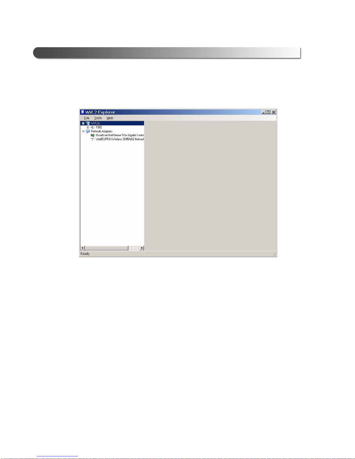
Overview: Using the WVL2 Explorer
The WVL2 Explorer provides the following menu options:
• File (page 62)
•Tools (page 63)
•Help (page 71)
Figure 4.1 WVL2 Explorer
Each menu option includes a number of features. Each of the menu options are
discussed in the following sub-sections.
When you click on a WVL2 in the list in the left pane, the following tabs are
displayed:
• Configuration
•Firmware
i You may also see an Items Requiring Your Attention tab. For informa-
tion on this tab, see “Two Conditions to Watch For” in Appendix A, later in
this manual.
56 WVL2™ Installation and Setup Manual

- Overview: Using the WVL2 Explorer
NOTE:
Configuration
The Configuration tab provides the following information:
• Device Name
• Wireless Settings
• Internet Protocol (TCP/IP) Settings
This information can be useful when troubleshooting network connection problems. You can also start here to set up encryption for your network.
i For assistance with setting up encryption, please contact Customer Sup-
port at 1-800-639-6774.
To access the Configuration tab:
1 Click on a WVL2 from the list located in the left pane of the WVL2 Explorer
(e.g., 597).
WVL2™ Installation and Setup Manual 57

Chapter 4 • The WVL2 Explorer
The Configuration tab is displayed.
Figure 4.2 Configuration Tab
2 Review the information displayed on the Configuration tab.
58 WVL2™ Installation and Setup Manual

- Overview: Using the WVL2 Explorer
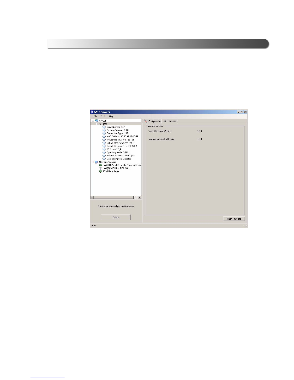
Firmware
The Firmware tab provides the following information:
• Current Firmware Version
• Firmware Version for Upd a te
This information will aid Customer Support technicians should you require technical support.
To access the Firmware tab:
1 Click on a WVL2 from the list located in the left pane of the WVL2 Explorer
(e.g., 597).
2 Click on the Firmware tab.
The Firmware tab is displayed.
Figure 4.3 Firmware Tab
3 When the “Firmware V ersion for Update” number is higher than the “Curren t
Firmware V ersion” number (as in Figure 4.3), click the Flash Firmware button
in the lower right corner.
WVL2™ Installation and Setup Manual 59

Chapter 4 • The WVL2 Explorer
NOTE:
i If you need assistance updating the firmware, please contact Customer
Support at 1-800-639-6774.
The following message is displayed.
Figure 4.4 Update Firmware Confirmation Message
4 Click Yes to start the firmware update process.
The process may take a few minutes.
When the process is complete, the following message is displayed.
Figure 4.5 Firmware Update Successful/Power Cycle Message
5 Click OK the close the message.
6 Disconnect power to the WVL2 unit.
The following message is displayed.
Figure 4.6 Firmware Update No Longer Detected Message
7 Click OK to close the message.
60 WVL2™ Installation and Setup Manual
- Overview: Using the WVL2 Explorer
8 Reconnect power to the WVL2 unit.
When the unit has powered up, the Items Requiring Your Attention tab is
no longer displayed.
The Firmware tab indicates that the firmware version is current.
Figure 4.7 Firmware Tab
WVL2™ Installation and Setup Manual 61

Chapter 4 • The WVL2 Explorer
The File Menu
The File menu has one feature, Exit. You use the Exit feature to close the WVL2
Explorer.
To exit the WVL2 Explorer:
1 Select File from the WVL2 Explorer menu bar.
2 Select Exit.
The WVL2 Explorer closes.
62 WVL2™ Installation and Setup Manual

The Tools Menu
The Tools menu provides the following features:
•Ping
•Options...
Ping
The Ping feature uses the PING protocol to check for the presence of a device on
the network.
To check for a device:
1 Select Tools from the WVL2 Explorer menu bar.
2 Select Ping.
- The Tools Menu
Figure 4.8 Ping Message
3 Enter the IP address of the device you want to locate ( e.g., 192.168.123.107).
4 Click Start.
WVL2™ Installation and Setup Manual 63

Chapter 4 • The WVL2 Explorer
The WVL2 Explorer searches for the device and, if found, displa ys the reply.
Figure 4.9 A Successful Ping
5 Click Stop.
6 Click the Close button on the dialog box.
64 WVL2™ Installation and Setup Manual

Options
The Options feature provides the following features, which are accessible by
means of tabs at the top of the Options menu:
• Application
• Connection Manager
• Discovery
- The Tools Menu
Figure 4.10 Options Menu
Application Feature
You use the Application feature to manage when WVL2 Explorer opens. The
default is to automatically open the WVL2 Explorer when Windows starts.
To change the default and disable this feature:
1 Select Tools from the WVL2 Explorer menu bar.
WVL2™ Installation and Setup Manual 65

Chapter 4 • The WVL2 Explorer
NOTE:
2 Select Options...
Figure 4.11 Options Me nu
3 Click on the check box to remove the check mark next to the Start WVL2
Explorer when Windows st arts feature.
4 Click OK.
Connection Manager Feature
You use this feature to manage when the Co nnection Manager is displayed. When
this feature is turned on, the Connection Manager is displayed before co nnecting
to a vehicle application.
i This feature can be useful if you have multiple WVL2s.
To change the default:
1 Select Tools from the WVL2 Explorer menu bar.
66 WVL2™ Installation and Setup Manual

2 Select Options...
- The Tools Menu
Figure 4.12 Options Menu
3 Select the Connection Manager tab.
WVL2™ Installation and Setup Manual 67

Chapter 4 • The WVL2 Explorer
The Connection Manager tab is activated.
Figure 4.13 Connection Manager
4 Click on the check box to add a check mark next to the Display Connection
Manager before connecting vehicle application feature.
5 Click OK.
68 WVL2™ Installation and Setup Manual

- The Tools Menu
Discovery Feature
You use the Discovery feature to manage when to display the New WVL2 notification message box. The default is to display the notification me ssage box when
a new WVL2 is detected.
To change the default:
1 Select Tools from the WVL2 Explorer menu bar.
2 Select Options...
Figure 4.14 Options Menu
3 Select the Discovery tab.
WVL2™ Installation and Setup Manual 69

Chapter 4 • The WVL2 Explorer
Figure 4.15 Discovery
4 Click on the check box to remove the check mark next to the Show New
WVL2 Notification option.
5 Click OK.
70 WVL2™ Installation and Setup Manual

The Help Menu
The Help menu has one feature, About. You use the About feature to display information about the WVL2 Explorer.
To access the Help menu:
1 Select Help from the WVL2 Explorer menu bar.
2 Select About.
- The Help Menu
Figure 4.16 About WVL2 Explorer
The information box provides version and copyright information.
WVL2™ Installation and Setup Manual 71
WVL2 Troubleshooting
Information
LED Issues, page 74
Configuration Issues, page 75
Wireless Communication Issues, page 76
Vehicle Application Issues, page 78
5
This chapter provides troubleshooting information to assist you in resolving issues that
may arise when setting up and using the WVL2.
WVL2™ Installation and Setup Manual 73

Chapter 5 • WVL2 Troubleshooting Information
LED Issues
The following table lists some possible causes and solutions to issues related to
the light-emitting diodes (LEDs) on the WVL2:
Problem Possible Cause Solution
Power LED on the
WVL2 does not
come on.
Fault LED on WVL2
is on.
Loose or faulty cable or
adapter.
• The WVL2 is
configured for
Infrastructure Mode
(Networked via
Access Point), but
the WVL2 cannot
find the Access
Point.
• The wireless card
inside the WVL2 is
loose or has been
removed.
• There may be a
hardware problem.
Check connections between
WVL2 and the vehicle.
Verify that the Access Point
is on and within range (100
ft.) of the PC and WVL2.
If this does not solve the
problem, refer to “Wireless
Communication Issues,“
later in this chapter.
Remove the four screws on
the back of the WVL2 and
ensure that the wireless PC
card is securely installed.
Contact NEXIQ™ Technical
Support at:
1-800-639-6774.
74 WVL2™ Installation and Setup Manual

Configuration Issues
The following table lists some possible causes and solutions to issues that may be
experienced when configuring the WVL2 and/or PC for wireless communication:
Problem Possible Cause Solution
- Configuration Issues
Wireless LED is not
illuminated
No association
between the WVL2 and
the PC has been made
(wrong SSID)
Configure the WVL2 and the
PC for the same SSID.
Refer to Figure 2.16:
Wireless Network Properties
in Chapter 2 of this manual.
You can see the SSID for the
device by viewing the
Configuration tab of the
WVL2 Explorer (Figure 4.2).
out is designed to present body elements (e.g., ChapIntro, Body Text, Bullets, etc.), not headings.
Headings on this page produce alignment If the introduction paragraphs
WVL2™ Installation and Setup Manual 75

Chapter 5 • WVL2 Troubleshooting Information
Wireless Communication Issues
The following table lists some possible causes and solutions to issues that may be
experienced when attempting to set up the WVL2 for wireless communication:
Problem Possible Cause Solution
WVL2 Explorer
cannot find the
WVL2.
• No power received
from the WVL2.
• The WVL2 is out of
range, or is
improperly
configured.
• Wireless card is
missing from PC,
or is not properly
configured.
Verify that the ve hicle ignition is
on, then check the connections
between the WVL2 and the
vehicle.
Verify that the WVL2 is within
100 ft. of the wireless PC.
Verify that the following
settings are the same for the
WVL2 and the PC:
• SSID
• Communication Mode (Ad
hoc)
• Encryption Settings
Verify that the wireles s network
card is properly installed on the
PC, the appropriate drivers are
installed, and the card is
properly configured.
Be sure that the following
match for all devices on the
same network:
• SSID
• Communication Mode (Ad
hoc)
• Encryption Settings
You can check the connection status of the WVL2 by referr ing to the WVL2 icon
76 WVL2™ Installation and Setup Manual
• Access Point is
OFF, out of range,
or improperly
configured
(Infrastructure
Mode only).
Verify that the Access Point is
operational and within range
(100 ft.) of the PC and WVL2.
Ensure that the Access Point is
configured for the same SSID
and Encryption Settings as the
PC, and that the WVL2 is on
the wireless network.

- Wireless Communication Issues
located in the system tray on your desk top.
The WVL2 Explorer icon has three states, indicated by the color of the icon:
How the icon looks What it means
Green center—A WVL2 has been detected and it is
the selected WVL2
White center—A WVL2 has been detected, but it
has not been selected.
In most cases, this is an indication that you have
more than one WVL2, and one of the devices is not
selected.
Grayed out—No WVL2 has been detected.
WVL2™ Installation and Setup Manual 77

Chapter 5 • WVL2 Troubleshooting Information
Vehicle Application Issues
The following table lists some possible causes and solutions to issues that may be
experienced when attempting to use a vehicle application with the WVL2:
Problem Possible Causes Solution
Vehicle Application reports
an error when
attempting to
connect to the
vehicle.
• There may be a
wireless
communication
problem.
• Wrong device
selected.
• Wrong Protocol
selected.
•The WVL2
Explorer is
configured to
launch
automatically and
a time-out has
occurred in the
diagnostic
application.
Verify that the WVL2 Explorer can
locate the WVL2. If not, refer to
“Wireless Communication Issues,”
earlier in this chapter.
Verify that the vehicle application has
been properly configured for use with
the WVL2.
Some vehicle applications allow connection to a vehicle using more than
one protocol. Verify that the proper
protocol has been selected in the
vehicle application.
Some vehicle applications report an
error if a connection does not occur
within a specified time-out. If this
happens, disable the Connection
Manager feature in the WVL2
Explorer when using the problem
application.
78 WVL2™ Installation and Setup Manual
• The vehicle
application
software is not
RP1210A
compliant. (TMC
Recommended
Practice RP1210A
defines a standard
Windows
Application
Program Interface
for vehicle
communications.)
Certain vehicle applications are hard
coded to use only specific hardware
and are not RP1210A-compliant.
These applications are not compatible with the WVL2.
For assistance, contact NEXIQ™
Technical Support at:
1-800-639-6774.

Setting Up a Second
WVL2
Overview, page 80
Setting Up a Second WVL2, page 81
Two Conditions to Watch For, page A-85
Firmware Conflict, page A-85
IP Address Conflict, page A-87
A
This appendix provides you with instructions for setting up a second WVL2 for use on a
single wireless network.
WVL2™ Installation and Setup Manual 79

Appendix A • Setting Up a Second WVL2
NOTE:
Overview
If you are installing more than one WVL2 on a single network, you don’t need to
reinstall the WVL2 drivers or configure the wireless network card for the second
WVL2. You already performed those tasks when you set up the first WVL2 (see
Chapter 2: Setting Up Wireless Communication, earlier in this manual).
All you have to do is disconnect the first WVL2 from the vehicle. Then, connect the
second WVL2. Once connected, you open the WVL2 Explorer (see Chapter 4:
The WVL2 Explorer, earlier in this manual) and change the IP address for the
second WVL2.
i If you encounter either a Firmware Conflict or an IP Addre ss Con flic t, you
must resolve these issues before proceeding (see “
Watch For,” later in this appendix.
Following this change you can reconnect the first WVL2 and use both devices.
Two Conditions to
80 WVL2™ Installation and Setup Manual

Setting Up a Second WVL2
NOTE:
NOTE:
i When setting up a second WVL2, each device must have a unique IP
address.
To set up a second WVL2:
This procedure assumes that you have installed the WVL2 drivers and utilities,
configured the wireless network card, and that the first WVL2 is connected to both
the vehicle and to your PC.
i For details, refer to Chapter 2: Setting Up Wireless Communication, earlier
in this manual.
1 Disconnect the first WVL2 from the vehicle.
Setting Up a Second WVL2
2 Connect the second WVL2 to the vehicle using the adapter cable provided
(i.e., the 6- and 9-pin Deutsch Y cable).
3 Verify that the following Notification message box is displayed.
Figure A.1 Notification: A WVL2 has been detected
The WVL2 is now connected to the vehicle and detected by the software
application.
WVL2™ Installation and Setup Manual 81
Appendix A • Setting Up a Second WVL2
4 Click on the WVL2 Explorer icon (located in the system tray on your PC’s
desktop.
Figure A.2 WVL2 Explorer
5 Click on the WVL2 in the list located in the left pane of the WVL2 Explorer (e.g.,
1002).
82 WVL2™ Installation and Setup Manual

The Configuration tab opens.
NOTE:
Setting Up a Second WVL2
Figure A.3 Configuration Tab
i Both WVL2s must have the same SSID (e.g., WVL2_A).
6 Change the last three elements of the IP address in the first box in the bottom third
of the display (e.g., change 100 to 116).
7 Click the Select button to select the highlighted WVL2 as your diagnostic device.
WVL2™ Installation and Setup Manual 83

Appendix A • Setting Up a Second WVL2
The WVL2 Explorer screen is refreshed.
Figure A.4 Second WVL2 Selected
The second WVL2 is now selected and ready for use.
84 WVL2™ Installation and Setup Manual

Two Conditions to Watch For
Two Conditions to Watch For
There are two error conditions that may require your attention when installing
multiple WVL2s:
• Firmware Conflict
• IP Address Conflict
Should you encounter either of these problems, do not proceed with setting up a
second WVL2.
Firmware Conflict
If you encounter a Firmware Conflict, you will notice the appearance of the Items Requiring Your Attention tab in the WVL2 Explorer.
Figure A.5 Items Requiring Your Attention Tab
WVL2™ Installation and Setup Manual 85

Appendix A • Setting Up a Second WVL2
When you click on the Items Requiring Your Atten tion tab, a message is displayed
informing you of the nature of the item.
Figure A.6 Items Requiring Your Attention Tab selected
But even without clicking on the tab, you can tell the nature of the item requiring
attention by the Yellow Caution Shield in the information pane on the left of the
WVL2 Explorer (see Figure A.6).
The Explorer is telling you that the firmware is out of date an d needs to be update d.
Clicking on the Firmware tab enables you to compare Current Firmware Version
and Firmware Version for Update.
If you encounter this problem, contact Customer Support at 1-800-639-6774.
86 WVL2™ Installation and Setup Manual

Two Conditions to Watch For
IP Address Conflict
If you encounter an IP Address Conflict, you will notice the appearance of the Items
Requiring Your Attention tab in the WVL2 Explorer.
Figure A.7 Configuration Tab
Even without clicking on the tab, you can tell the nature of the item requiring a ttention
by observing the yellow shield displayed in the information pane on the left of the
WVL2 Explorer.
WVL2™ Installation and Setup Manual 87

Appendix A • Setting Up a Second WVL2
When you click on the Items Requiring Your Atten tion tab, a message is displayed
informing you of the nature of the item (e.g., Duplicate IP Address).
Figure A.8 Items Requiring Your Attention Tab
To change the IP address, click on the Configuration tab and change the IP Address
for the second device (e.g., change the last three digits of the address from 110 to
130.).
Each device must have a unique IP address.
88 WVL2™ Installation and Setup Manual
 Loading...