

Page 1

PEAK 632A
Single Board Computer
User
All brand names are registered trademarks of their respective owners.
′′′′
s Manual
Page 2

Copyright 2000
All rights reserved
Edition 1.0 July, 2000
The information in this document is subject to change w ithout prior notice in order to improve
reliability, design and function. The information in this docum ent does not represent
commitm ent on the part of the m anufacturer.
In no event will the manufacturer be liable for direct, indirect, special, incidental, or
consequential damages arising out of the use of the PEAK 632A , nor for any infringements upon
the rights of third parties which may result from such use.
This document contains proprietary inform ation protected by copyright. All rights are reserved.
No part of this manual m ay be reproduced by any mechanical, electronic, or other m eans in any
form without prior written per m ission of the manufacturer.
Trademarks
PEAK 632A is a registered trademark of NEXCOM International Co., L td.
IBM PC is a registered trademark of International Business Machines Corporation.
Intel and Pentium are registered trademarks of Intel Corporation. Award is a registered
trademark of Award Software, Inc.
Other product names m entioned herein are used for identification purposes only and may be
trademarks and/or registered tradem arks of their respective com panies.
Page 3

Table of Contents
How to Use This Guide
Chapter 1 Introduction
1.1 Intro d uction.................................. ................... .......... ............-1
1.2 Features
1.3 Specifications
1.4 Packing List
Chapter 2 Switche s and Connectors
2.1 Switches..................................... ........... ......
2.2 Connectors...................................................................................2-4
Chapter 3 System Memory and CPU Installation
3.1 System Memory.......................................................................3-1
3.2 Cache Memory ........................................................................3-3
3.3 Chang CPU..................................................................
……..
..
..........................2-1
….1-1
.1-2
1-6
3-
Chapter 4 Award BIOS Setup
4.1 Entering Setup.........................................................................4-1
4.2 Control Keys .....................
4.3 Getting Help ............................…................................................ 4-3
4.4 The Main Menu ........................................................................... 4-4
4.5 Standard CMOS Setup ............................................................ 4-7
4.6 BIOS Features Setup. ..................…...........................................-11
4.7 Chipset Features Setup............................................................…4-16
4.8 Power Management Setup...........................................................4-20
4.9 PnP/PCI Configuration..........................................................….4-25
........................................... 4-2
Page 4

4.10 IDE HDD Auto Detection ......................................................... 4-31
4.11 Supervisor/User Password Setting.............................
4.12 IDE HDD Auto Detection
4.13Power-On Boot
4.14 BIOS Reference – POST messages
4.15 BIOS Default Drive Table
…...
….
….
Chapter 5 VG A Driver Installation Procedures
5.1 Windows 95/98 Drivers Setup Procedure
5.2 Windows NT Drivers Setup Procedure
Chapter 6 LAN Driver Installation Procedures
6.1 Windows 95/98 Drivers Setup Procedure
6.2 Windows NT Drivers Setup Procedure
Chapter 7 SC SI Driver Installation Procedures
….......4-35
........................................4-36
.......................
-41
4-42
….….4-48
…
…..5-1
.. 5-12
..…6-1
...….… 6-6
6.1 Windows 95/98 Drivers Setup Procedure
6.2 Windows NT Drivers Setup Procedure
Appendix A Watchdog Timer
Appendix B Memory Mapping
...
..…6-1
7-11
Page 5

How to use this manual
This manual is writte n to help you use the PCA- 6551VE. It describes how to ma ke various
settings on the Pentium
follows:
®
CPU board to meet y our requirements. A brief sum mary of the manual
Chapter 1
what is included in the product package.
Chapter 2
connectors that you may easily configure and set up according to your particular requirem ents.
Chapter 3
the system m emory , cache mem ory, and/or CPU. These changes will y ield more power from the
CPU board.
Chapter 4
almost every feature of the PCA-6551VE , including the watchdog tim er.
Chapter 5
the software drivers on the utility disk included in y our package.
Chapter 6
configur ation, and shows how to change the configuration to match your application
requirements.
“Introductiongives an overview of the product specifications. It also tells you
umpers and Connectorsdescribes the definitions and positions of jumpers and
ystem Expansiondescribes how to change or expand the CPU board by changing
ward BIOS Setupdescribes how to use the advanced PCI/Green BIOS to control
“VGA Driver Installation Procedures” gives instructions for installing and operating
“LAN Driver Installation Procedures” provides detailed information on Ethernet
Chapter 7
and operating the software drivers, and shows how to change the configura tion to match your
application requirements.
Appendix A
an example of programm ing the W D T.
Appendix B
“SCSI Driver Installation Procedures” provides detailed inform ation for installing
“Watchdog Timer”describes how to set up the watchdog tim er (WDT ), and gives
“Memory Mapping” describes usage of the 1st MB mem ory .
Page 6

Peak 632A User's Guide
Chapter 1
1-1 Introduction
The PEAK 632A is a full size Sing l e Bo ard Computer. It appli e s Si ng l e Soc k et 370
FC-PGA based processor, supporting both 66 MHz (Celeron) and 100 MHz (Pentium
III) Front Side Bus. The memory it can accommodat e i s 1 GB SDRAM up to 100
MHz.
Meanwhile, this card is on-board with the following three significant I/Os which help
to spare out more PCI slots for other add-on I/Os, i.e. the C&T 69000/69030
VGA/Panel controller through AGP interface; the Intel 82559 Ethernet and the
Adaptec 7890 Ultra 2 SCSI. Components with a ll o f the a bov e branded a nd
powerful. PEAK 632A is o bviously a fo r midable platform ideal for heavy duty and
computer telephony application.
The other on-board I/Os includes 2S1P, the high precision RTC with battery, the
Watch Dog Timer, DOC, IDE×2, FDC×1, USB×2, and PS/2 Keyboard/Mouse.
1-2 Features
!
Intel Celeron/Pentium III CPU with 66/100MHz FSB up to 850 MHz
!
1 GB SDRAM (Max.) memory support, DIMM×4
!
Intel 440BX AGP set
!
C&T 69000 AGP mode VGA controller with CRT/LCD support
!
Intel 82559 10/100 Base Ethernet control ler
!
Adaptec 7890 U2 SCSI controller
!
On board socket for DiskOnChip up to 288MB
!
RS232×2 with 16C550 UARTs, optional RS422/485×1
!
Enhanced parallel port, support SPP/EPP/ECP
!
IDE×2, FDC×1, PS/2 keyboa rd/mouse
!
USB port×2
!
Watchdog Timer
!
ISAMAX support up to 20 slots ISA car d
Specifications
1-1
Page 7

Peak 632A User's Guide
1-3 Specifications
!
System Architecture
!
Full size SBC with PCI/ISA Golden finger
!
Intel Socket 370 Celeron/Pentium III with 66/100MHz FSB
!
PCI V2.1 complied
!
PICMG 1.0 (Rev.2. 0) complied
!
CPU Support
!
Intel Celeron/Pentium III CPU with 128/256K cache on die
!
Brand New Sock e t 370 FC-PGA CPU running at 66/ 100MHz FSB up to 850MHz
!
Support strea ming SIMD instr uc t i o n
!
Main Memory
!
Support SDRAM up to 1GB ( Ma x.)
!
168 pin DIMM socket×4
!
ECC support (single bit error correction/Multiple bit errors reporting)
!
BIOS
!
Award System BIOS
!
Plug & Play support
!
Advanced Powe r Mana ge me nt s uppor t
!
Advanced configuration & Power Interface support
!
2M bit flash ROM
!
Chip Set
!
Intel 82440BX AGP set
!
66/100MHz FSB support
!
PCI V2.1 complied
!
Optimized SD RAM s uppor t
!
On Board VGA
!
C&T 69000 AGP mode VGA contr oller
!
TFT LCD/DSTN LCD/CRT co nt r o l
Specifications
1-2
Page 8

Peak 632A User's Guide
!
2MB SDRAM on die
Maximum Res.
Color & Refresh
Rate
Resolution
Colors Refresh Rate (Hz)
1280×1024
1024×768
800×600
!
Driver supportWindows 95/98, Window s NT4.0
!
15 pin CRT connector×1, 50 pin LCD panel connector×1
!
On Board LAN
!
Intel 82559 Single Ethernet controller
!
10 Base T/100 Base TX support, full duplex
!
Complied wi t h PCI V2.1, IEEE802.3, IEEE 802.3U
!
Backward compatible with former 82558 Ethernet controller base net modules
!
Driver support: DOS/Window s , Windows 95/98, Windows NT4.0, Netwa re , SCO
16bits (High color ) 85, 75, 65
24bits (True color) 85, 75, 65
256 60
Open Server 5.0
!
RJ45 connector×1
!
On Board SCSI
!
Adaptec AIC 7890 RISC SCSI c o nt r o l l e r
!
Brand New Ultra 2 SCSI support
!
80MB/s (Max.) transfer rate, up to 12 meter cable
!
Backward compatible with Ultra Wide SC SI, SCSI II, etc.
!
Driver support: Windows 95/98, Windo ws NT4.0, SCO Open Server 5.0
!
68 pin SCSI connect o r×1
!
On Board I/O
!
Winbond W83977 Super I/O on board
!
SIO×2, with 2×16C550 UARTs, 9 pin D-type×1, 10 pin HEADER×1, optional
RS422/485×1
!
PIO×1, Bi-directional, EPP/ECP support, 26 pin×1
!
Floppy Disk controller: 5.25″360K/1.2MB, 3.5
Specifications
″
1-3
Page 9

Peak 632A User's Guide
720K/1.2MB/1.44MB/2.88MB support , 34 pi n c onnector×1
!
On chip enhanced IDE×2, PIO up to mode 4, DMA master up to mode 2,
Ultra DMA/33 support, 40 pin×2, total 4 E.IDE Devices support
!
On chip keyboard, mouse controller, PS/ 2 KeyboardMouse, 5 pin header
×
1, 6 pin mini DIN×2, (for Peak632V/Peak632)PS/2 Keyboard, 6 pin
mini DIN×1, share with PS/2 mouse by Y cable
(for Peak632A/Peak632VL)
!
On board USB port×2 (6 pin header×1)
!
On board buzzer×1
!
On board 2 pin header for reset SW, 4 pin for speaker, 5 pin for keylock
!
On board 3 pin header fo r +5VSTBY, GND, Powe r ON#
!
On board 2 pin header for I2C
!
On board reserved CAN Bus connector
!
On Board RTC
"
High precision real time clock/calendar with battery back up
!
On Board Solid State Disk Socket
!
On board reserved socket for DOC of M-systems2MB~144MB, etc
!
System Monitor
!
Winbond W83782D system monitor controller
!
Six voltage (For +3.3V, +5V, +12V,−12V, Vtt and Vcore )
!
One Fan speed (For CPU)
!
Two temperature
!
Drivers support: Windows 95/98, Windo w s NT4.0
!
ISAMAX Support
!
MaximizeISA signals to support ISA cards up to 20
!
Watchdog Timer
!
1,2,44 seconds time-out intervals
!
Dimensions
!
340mm(D)×122mm(W)
!
Power Requirements
!
+5V20A (Max.)
Specifications
1-4
Page 10

Peak 632A User's Guide
!
+12V: 500mA (Max.)
!
-12V: 50mA (Max.)
!
Environments
!
Operating temperatures0°C to 60°C
!
Storage temperatures-20°C to 80°C
!
Relative humidity10% to 90% (Non-condensing)
!
Certification
!
CE approval
!
FCC Class A
!
Model Available
!
PEAK 632A--Full-size Socket 370 Celeron/Pentium III AIO CPU Ca rd
!
PEAK 632VL-- Full-size Socket 370 Celeron/Pentium III CP U Card
w/VGA/LAN
!
PEAK 632V-- Full-size Socket 370 Celeron/Pentium III CPU Card w/
VGA
!
PEAK 632-- Full-size Socket 370 Celeron/Pentium III CPU Card
Specifications
1-5
Page 11

Peak 632A User's Guide
1-4 What you'll have from t he package
In addition to this manual, the PEAK 632A series package includes the follow ing items.
ITEM
Peak 632A Peak 632VL Peak 632V Peak 632
Model
Peak 632A series
CPU card
IDE cable 1 1 1 1
FDC cable 1 1 1 1
Serial & Printer port
cable
5 pin to 5 pin
keyboard cable
Y cable for
keyboard & mouse
UW SCSI cable 1
C&T 69000 VGA
driver disks
Intel 82559
Ethernet driver
disks
Adaptec 7890
driver disks
Winbond W83782D
driver disks
1111
1111
1111
11
×××
111
22
3
3333
×××
××
××
×
If any of these items is missed or damaged, please contact y our vendor for what y ou
want.
Specifications
1-6
Page 12
Chapter 2
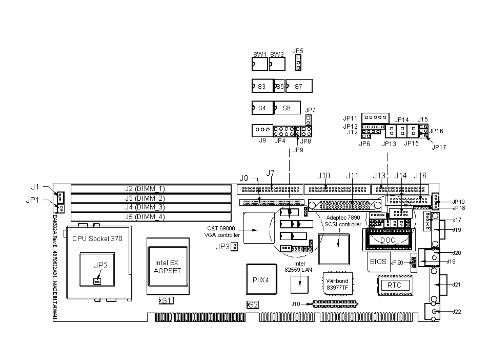
Figure 2-1 Switches and Connectors position
Page 13
Peak 632A User's Guide
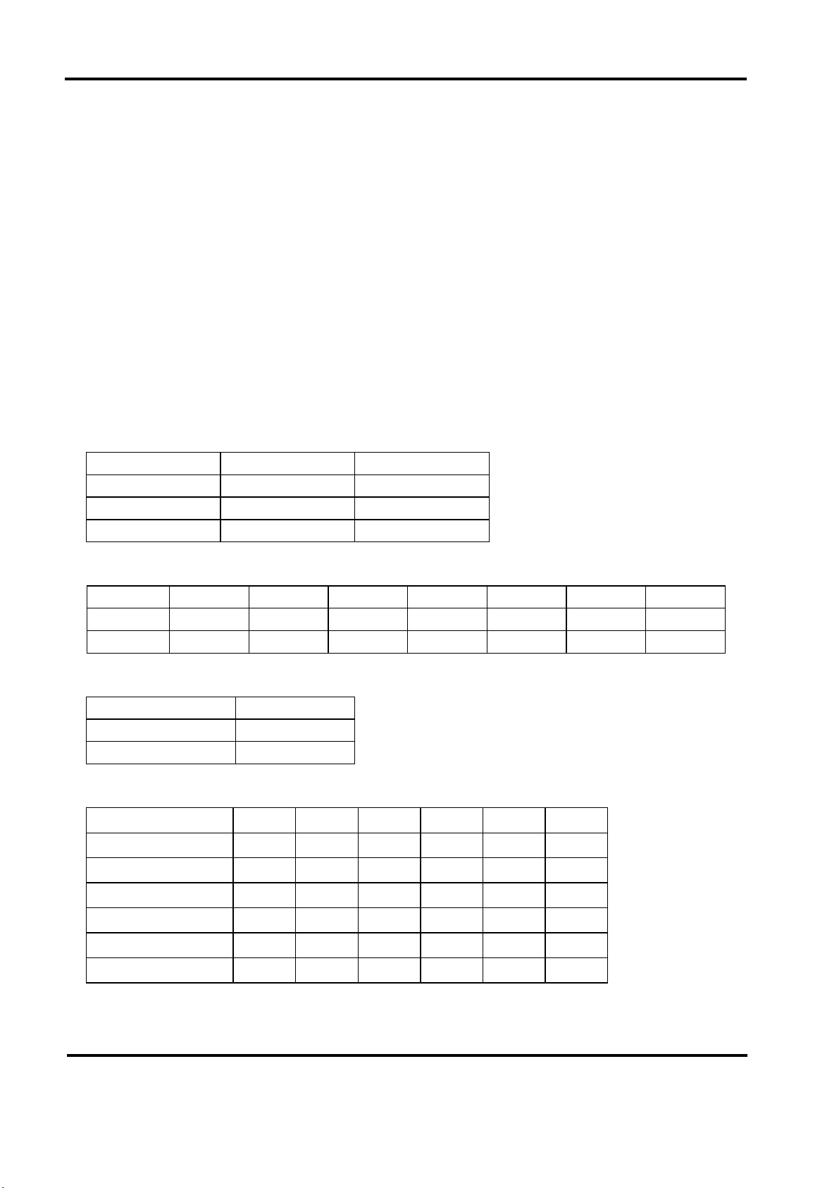
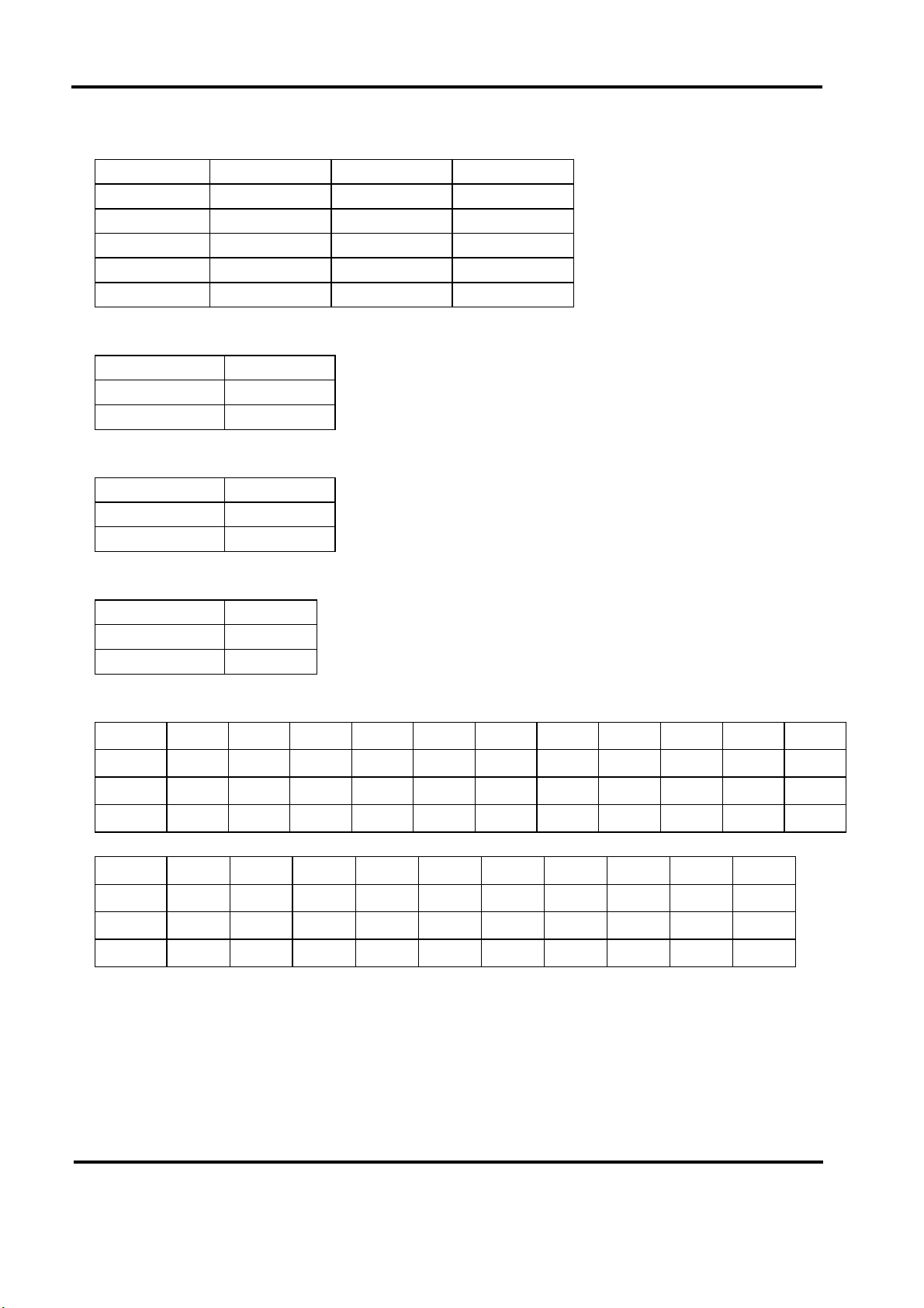
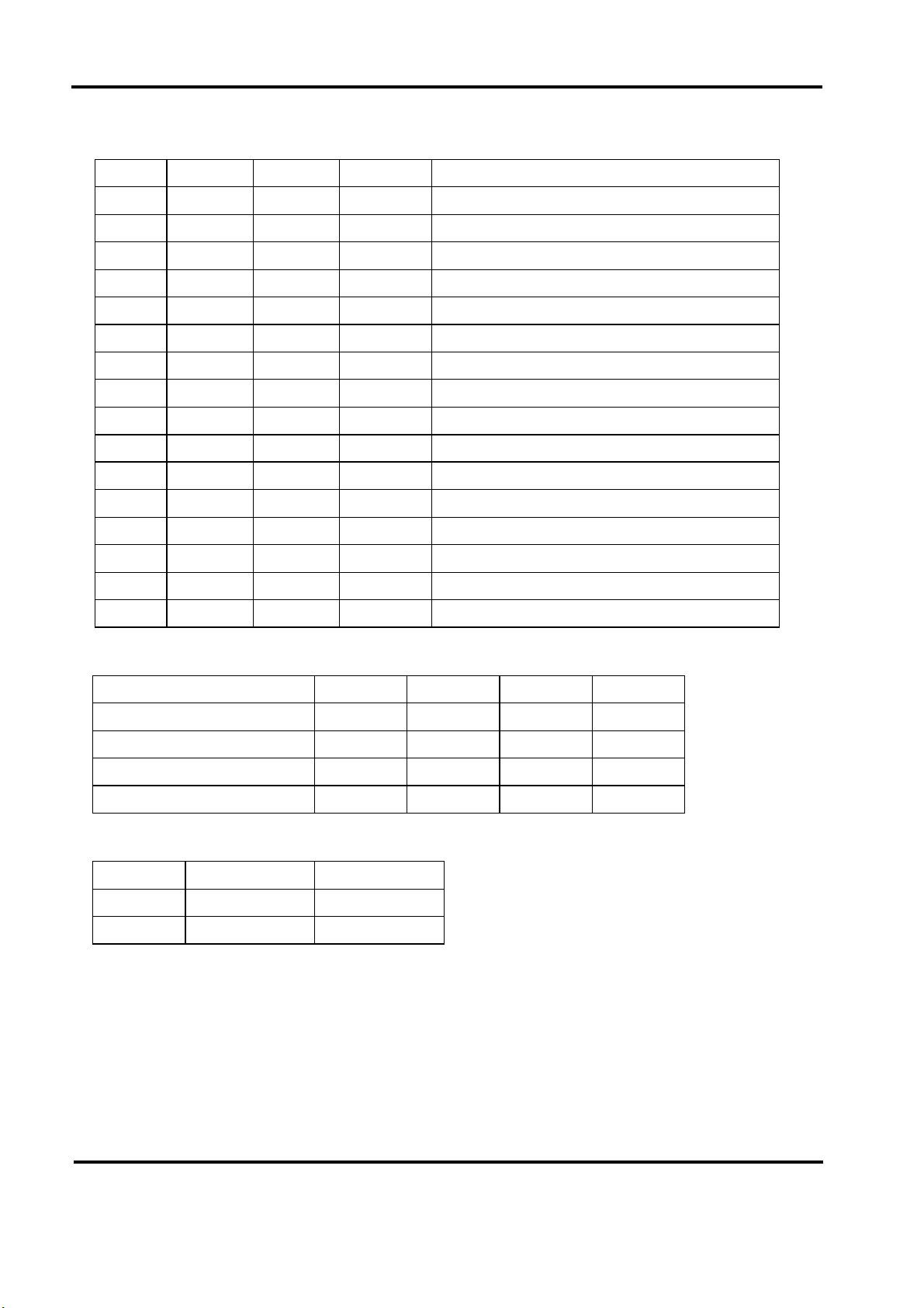
This chapter gives the definitions and shows where to locate the positions of
switches and connectors.
2-1 Switches
Switches on the CPU board are used to select options for different functions used.
The switch-on or off is to accommodate the variations of the following table.
Switch Setting Table (*: default setup)
AT/ATX FUNCTION SELECT
*AT Function ATX Function
JP4 1-2,3-4 5-6,7-8
JP7 N/C 1-2
JP8 1-2 3-4
CPU Frequency
S1.1 S1.2 S1.3 S1.4 S1.5 S1.6 S1.7
*100 OFF OFF ON OFF OFF OFF O FF
66 ON ON ON OFF OFF ON OFF
CPU Pipelined
S1.8
*Enabled OFF
Disabled ON
DEVICE SELECT
S2.1 S2.2 S2.3 S2.4 S2.5 S2.6
*VGA Enabled ON OFF X X X X
VGA Disabled OFF ON X X X X
*SCSI Enabled X X ON OFF X X
SCSI Disabled X X OFF ON X X
*LAN Enabled X X X X ON OFF
LAN Disabled X X X X OFF ON
Switches and Connectors
2-1
Page 14
Peak 632A User's Guide
M-System Disk On Chip
S4.1 S4.2 S4.3
Disabled OFF X X
C0000 ON ON ON
C8000 ON ON OFF
D0000 ON OFF ON
*D8000 ON OFF OFF
BIOS Fresh
S4.4
Enabled ON
*Disabled OFF
IRQ12 (Mouse Controller) Release
S4.6
*Enabled ON
Disabled OFF
RTC Clear
S4.5
Enabled ON
*Disabled OFF
COM2 RS232 /RS485/RS422
S7.1 S7.2 S7.3 S7.4 S7.5 S7.6 S7.7 S7.8 S3.1 S3.2 S3.3
*RS232 OFF ON OFF ON OFF ON OFF ON ON OFF OFF
RS485 ON OFF ON OFF ON OFF ON OFF OFF OFF ON
RS422 ON OFF ON OFF ON OFF ON OFF OFF ON OFF
S6.1 S6.2 S6.3 S6.4 S6.5 S6.6 S6.7 S6.8 S3.4 S3.5
*RS232 OFF ON OFF ON OFF ON OFF ON OFF ON
RS485 ON OFF ON OFF ON OFF ON OFF OFF OFF
RS422 ON OFF ON OFF ON OFF ON OFF ON OFF
Switches and Connectors
2-2
Page 15
Peak 632A User's Guide
PANEL DIRECTOR
SW2.4 SW2.3 SW2.2 SW2.1
On On On On 1024x768 Dual Scan STN Color Panel
On On On Off 1280x1024 TFT Color Panel
On On Off On 1024x768 Dual Scan STN Color Panel:
On On Off Off 1024x768 Dual Scan STN Color Panel
On Off On On 640x480 Sharp TFT Color Panel
On Off On Off 640x480 18Bit TFT Color Panel
On Off Off On 1024x760 TFT Color Panel
On Off Off Off 800x600 TFT Color Panel
Off On On On 800x600 TFT Color Panel
Off On On Off 800x600 TFT Color Panel
*Off On Off On 800x600 Dual Scan STN Color Panel
Off On Off Off 800x600 Dual Scan STN Color Panel
Off Off On On 1024x768 TFT Color Panel
Off Off On Off 1280x1024 Dual Scan STN Color Panel
Off Off Off ON 1024x600 Dual Scan STN Color Panel
Off Off Off Off 1024x600 TFT Color Panel
PANEL DIRECTOR
SW1.1 SW1.2 SW1.3 SW1.4
*MPCLK From PCLK ON OFF X X
MPCLK From M OFF ON X X
*DE From M X X ON OFF
DE From LP X X OFF ON
FLASH ROM SIZE
S5.1 S5.2
1M ON OFF
*2M OFF ON
Switches and Connectors
2-3
Page 16

Peak 632A User's Guide
2-2 Connectors
Jumper/Connector define
Connector Function Remark
J1 CPU Fan Header
J2, J3 , J4, J5 DIMM Socket
J7 HDD Connector
J8 Panel Connector
J9 ATX Power Connector
J10 HDD Connector
J11 SCSI Connector
J12 Speaker Connector
J13 FDD Connector
J14 COM2
J15 Reset Connector
J16 Parallel Connector
J17 USB Connector
J18 LAN, RJ45 Connector
J19 CRT Connector
J20 MOUSE Connector
J21 COM1
J22 KB/MS Connector
JP1, JP2, JP3 Temperature Connector
JP5 Panel Voltage Connector
JP6 SMBUS Connector
JP9 ATX Power Button
JP10 NEXCOM ISA Connect or
JP11 IR Connector
JP12 Key Lock
JP13 LAN Link LED
JP14 LAN Speed LED
JP15 LAN Active LED
JP16 HDD LED
JP17 SCSI LED
JP19 Keyboard Connector
JP20 LAN Connector
U21 M-SYSTEM DOC
Switches and Connectors
2-4
Page 17
Peak 632A User's Guide
Pin definitions of connectors
•••• J1: CPU Fan Header Connector
PIN No. Description
1GND
2 +12V
3Sense
• J7 /J10: HDD Connector
PIN No. Description PIN No. Description
1 Reset# 2 Ground
3 Data 7 4 Data 8
5 Data 6 6 Data 9
7 Data 5 8 Data 10
9 Data 4 10 Data 11
11 Data 3 12 Data 12
13 Data 2 14 Data 13
15 Data 1 16 Data 14
17 Data 0 18 Data 15
19 Ground 20 N/C
21 DMA REQ 22 Ground
23 IOW# 24 Ground
25 IOR# 26 Ground
27 IOCHRDY 28 Ground
29 DMA ACK 30 Ground
31 Interrupt 32 NC
33 SA1 34 N/C
35 SA0 36 SA2
37 HDC CS1# 38 HDC CS3#
39 HDD Active# 40 Ground
Switches and Connectors
2-5
Page 18

Peak 632A User's Guide
•••• J8: Flat Panel Connector
PIN No. Description PIN No. Description
1ENABLK 2+12VSAFE
3LP 4DE
5SHFCLK 6FLM
7P0 8VDD
9P2 10P1
11 P4 12 P3
13 P6 14 P5
15 P8 16 P7
17 P10 18 P9
19 P12 20 VDD
21 P14 22 P11
23 GND 24 P13
P16
P18
P15
P17
29 P20 30 ENAVEE
31 P22 32 P19
GND
P24
P21
P23
37 P26 38 P25
39 M/PCLK 40 GND
41 P28 42 P27
43 P30 44 P29
45 P32 46 P31
47 P34 48 P33
49 GND 50 P35
Switches and Connectors
2-6
Page 19
Peak 632A User's Guide
• J9: ATX Power Connec tor
PIN No. Description
15VSB
2GND
3Power On
•••• J12: Speaker Connector
PIN No. Description
1 Speaker Signal
2GND
3GND
4+5V
• J13: FDC Connector
PIN No. Description PIN No. Description
1 Ground 2 Density Select
3 Ground 4 N/C
5N/C 6Drate0
7 Ground 8 Index#
9 Ground 10 Motor Enable A#
11 Ground 12 Drive Select B#
13 Ground 14 Drive Select A#
15 Ground 16 Motor Enable B#
17 Ground 18 Direction#
19 Ground 20 Step#
21 Ground 22 Write Data#
23 Ground 24 Write Gate#
25 Ground 26 Track 0#
27 Ground 28 Write Protect#
29 GPI21 30 Read Data#
31 Ground 32 Head Side Select#
33 Ground 34 Disk Change#
Switches and Connectors
2-7
Page 20
Peak 632A User's Guide
• J14/J21: Serial Port Connector (D -Sub 9 -pin)
PIN No. Description
1 Data Carrier Detect (DCD)
2 Receive Data (RXD)
3 Transmit Data (TXD)
4 Data Terminal Ready (DTR)
5 Ground (GND)
6 Data Set Ready (DSR)
7 Request to Send (RTS)
8 Clear to Send (CTS)
9 R ing Indicator (RI)
•••• J15: Reset Connector
PIN No. Description
1 RESET
2GND
• J16: Parallel Port Connector
PIN No. Description PIN No. Description
1 Strobe# 2 Data 0
3 Data 1 4 Data 2
5 Data 3 6 Data 4
7 Data 5 8 Data 6
9 Data 7 10 Acknowledge
11 Bus y 12 Paper Empty
13 Printer Select 14 Auto Form Feed#
15 Error# 16 Initialize
17 Printer Select IN# 18 Ground
19 Ground 20 Ground
21 Ground 22 Ground
23 Ground 24 Ground
25 Ground 26 N/C
Switches and Connectors
2-8
Page 21
Peak 632A User's Guide
• J17: USB Connector
PIN No. Description
1+5V
2USBD03USBDO+
4USBD15USBD1+
6GND
• J18: LAN (RJ45) connector
PIN No. Description
1TD+
2TD3RD+
4TERMPLANE
5TERMPLANE
6RD7 TERMPLANE
8TERMPLANE
9NC
10 NC
11 GND
12 GND
• J19: CRT connector
PIN No. Description
1RED
2 Green
3Blue
4NC
5GND
6GND
7GND
8GND
9+5
10 GND
11 NC
12 Display Data channel data
13 Horizontal Sync
Switches and Connectors
2-9
Page 22
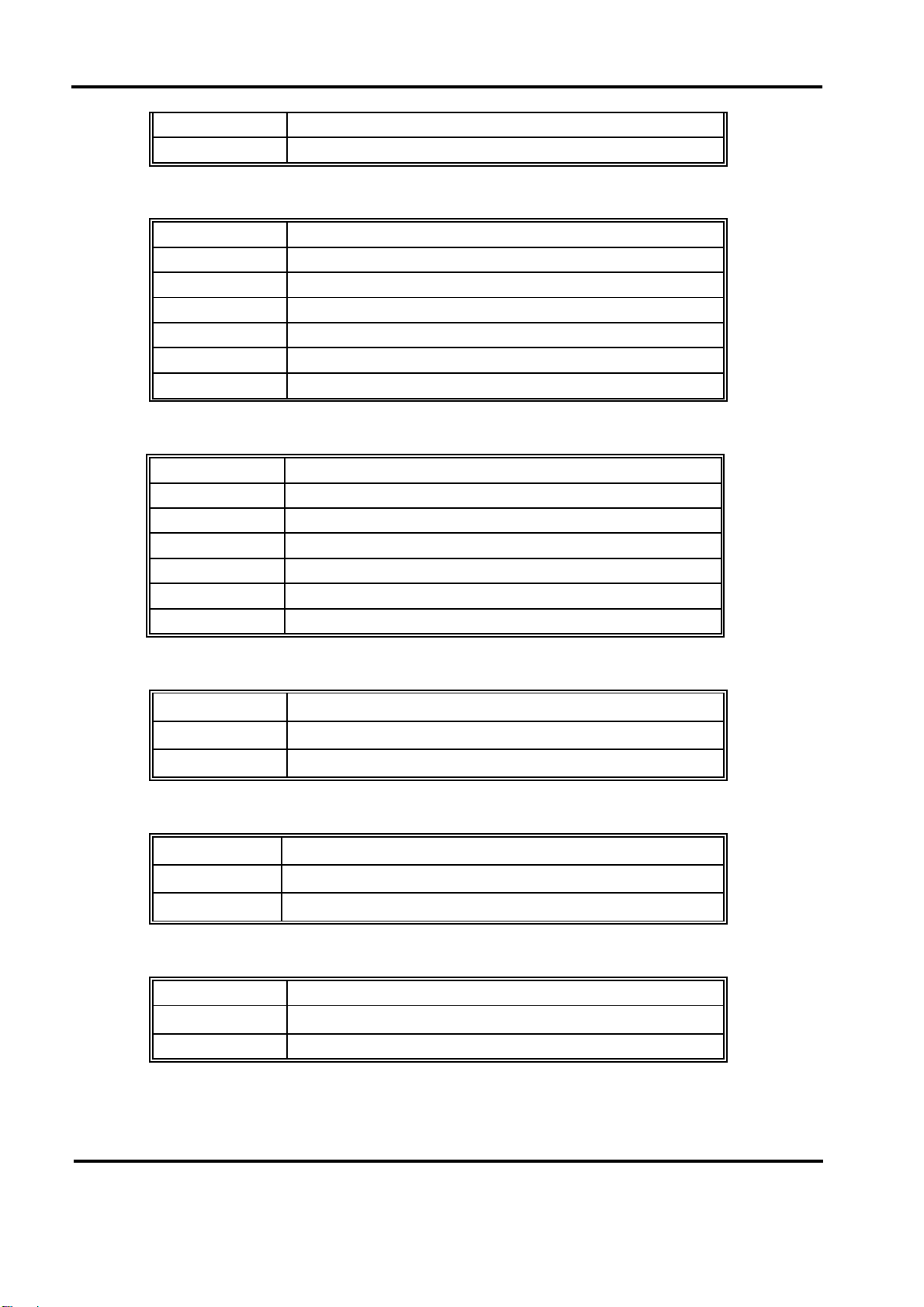
Peak 632A User's Guide
14 Vertical Sync
15 Display Data Channel CLK
• J20: Mouse connecto
r
PIN No. Description
1 Mouse Data
2N/C
3 Ground
4+5V
5 Mouse Clock
6N/C
• J22: Key Board/Mouse Connector
PIN No. Description
1KB/DATA
2 MS/DATA
3GND
45V
5 KB/CLK
6MS/CLK
• JP1/JP2/JP3: Temperature Connector
PIN No. Description
1 Temperature sensor
2GND
• JP5: Panel Voltage
PIN No. Description
1-2 For VDD 5V Panel
2-3 For VDD 3.3V Panel
• JP6: SMBUS Connector
PIN No. Description
SMBCLK
2SMBDATA
Switches and Connectors
2-10
Page 23
Peak 632A User's Guide
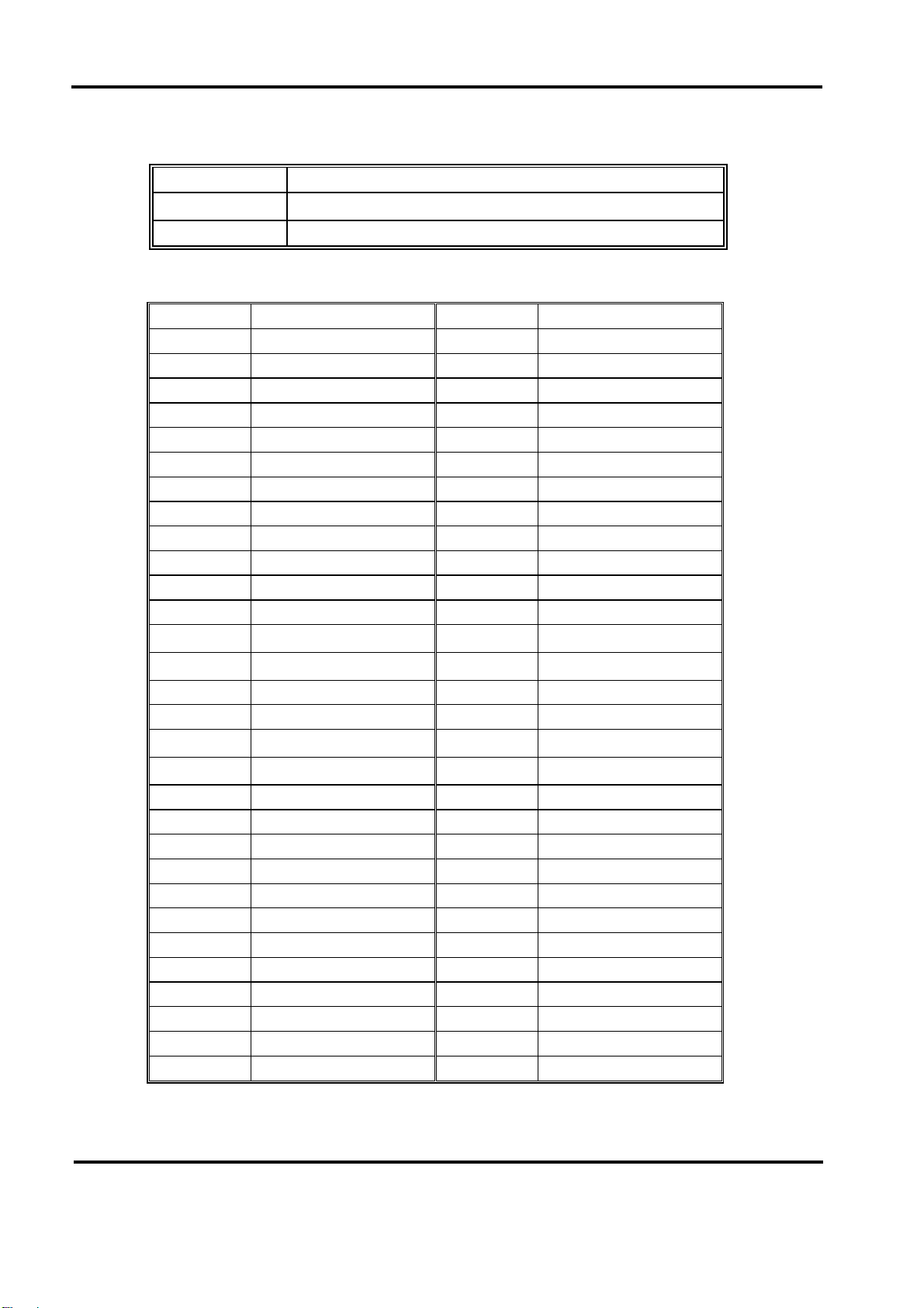
• JP9: ATX Power Button
PIN No. Description
2PWRBT#
• JP10: NEXCOM ISA Connector
PIN No. Description PIN No. Description
1 BRSTDRV 2 GND
3VCC 4SD7
5IRQ9 6SD6
7 -12V 8 SD5
9+12V 10SD4
11 GND 12 SD3
13 MEMW# 14 SD2
15 MEMR# 16 SD1
17 IOW# 18 SD0
19 IOR# 20 IOCHRDY
21 REFRESH# 22 BAEN
23 SYSCLK 24 SA9
IRQ7
+3.3V
SA8
IRQ5
SA7
29 IRQ4 30 SA6
31 IRQ3 32 SA5
BALE
VCC
SA4
SA3
37 GND 38 SA2
39 IRQ10 40 SA1
41 IRQ11 42 SA0
43 IRQ12 44 VCC
45 IRQ15 46 MEMR#
47 IRQ14 48 MEMW#
49 MASTER# 50 GND
51 MEMCS16# 52 SA10
53 IOCS16# 54 SA11
55 SBHE# 56 SA12
57 BTC 58 SA13
59 SA15 60 SA14
Switches and Connectors
2-11
Page 24
Peak 632A User's Guide
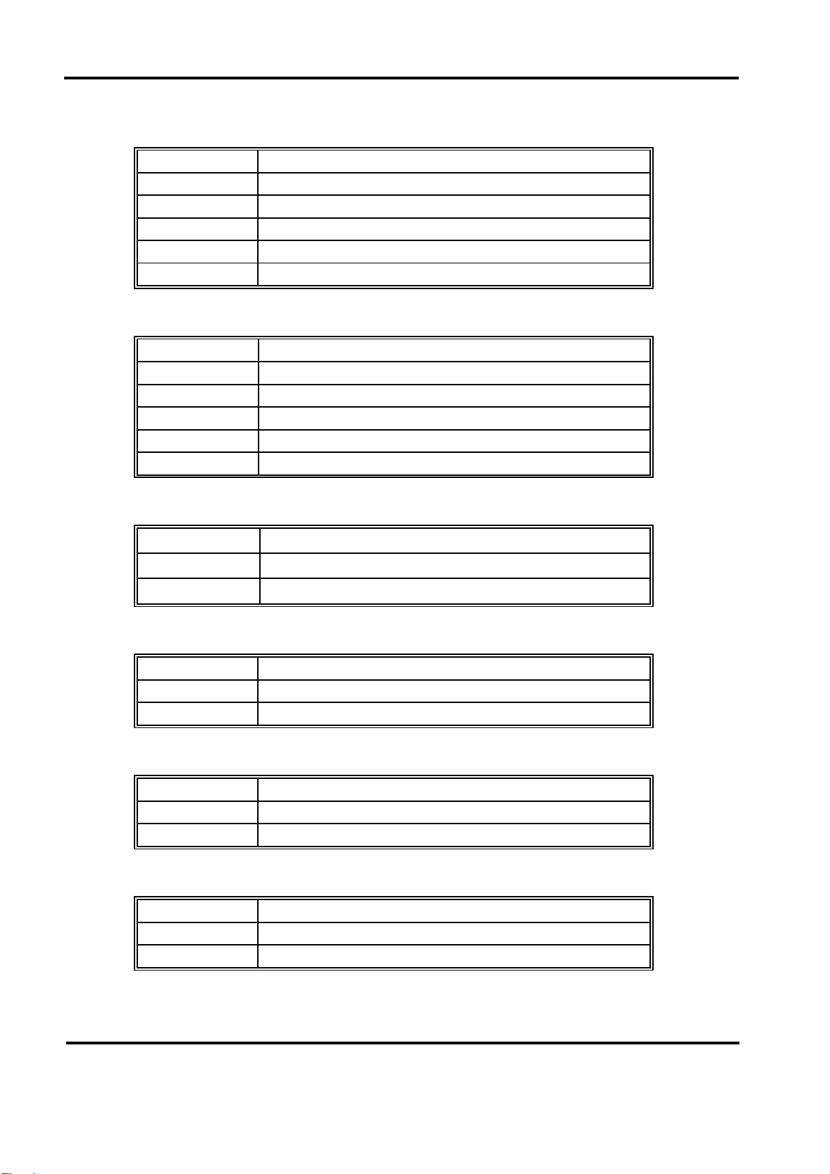
•••• JP11: IR Connector
PIN No. Description
15V
2 IRRXH
3 IRRX
4GND
5IRTX
• JP12: KEYLOCK Connector
PIN No. Description
1VCC
2N/C
3GND
4KEYLOCK
5GND
• JP13: LAN Link LED
PIN No. Description
1 +3.3V
2LINK#
• JP14: LAN Speed LED
PIN No. Description
1 +3.3V
2 100#
•••• JP15: LAN Active LED
PIN No. Description
1 +3.3V
2ACTIVE#
• JP16: IDE Active LED
PIN No. Description
1+5V
2ACTIVE#
Switches and Connectors
2-12
Page 25
Peak 632A User's Guide
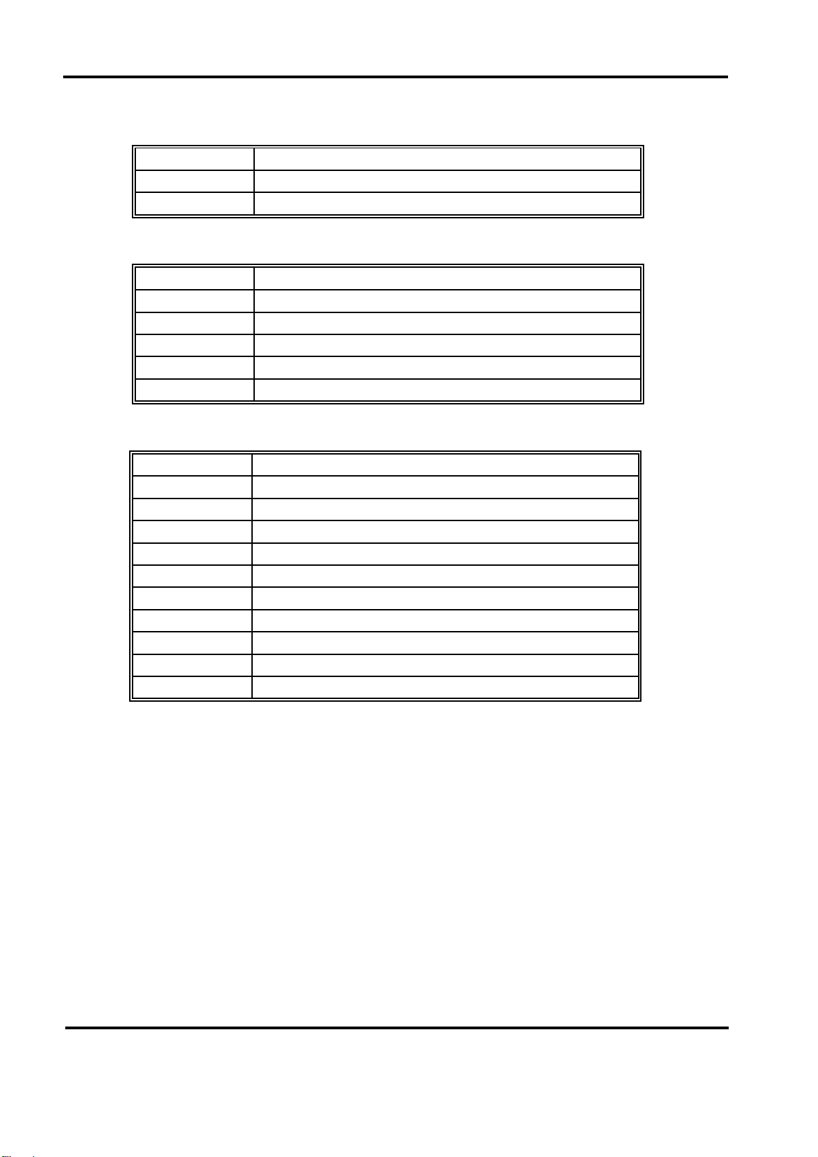
• JP17: SCSI LED
PIN No. Description
1 LED
2+5V
• JP19: Key Board Connector
PIN No. Description
1 Keyboard Clock
2 Keyboard Data
3N/C
4GND
5+5V
• JP20: LAN Connector
PIN No. Description
15V
2 LILED
3RD+
4RD5ACTLED
6TERMPLANE
7N/C
8TERMPLANE
9TD+
6TD-
Switches and Connectors
2-13
Page 26

Peak 632A User's Guide
Chapter 3
Capability Expanding
This chapter explains how you can expand capability of your CPU board in such
aspects as system memory, cache memory, and CPU.
3-1 System Memory
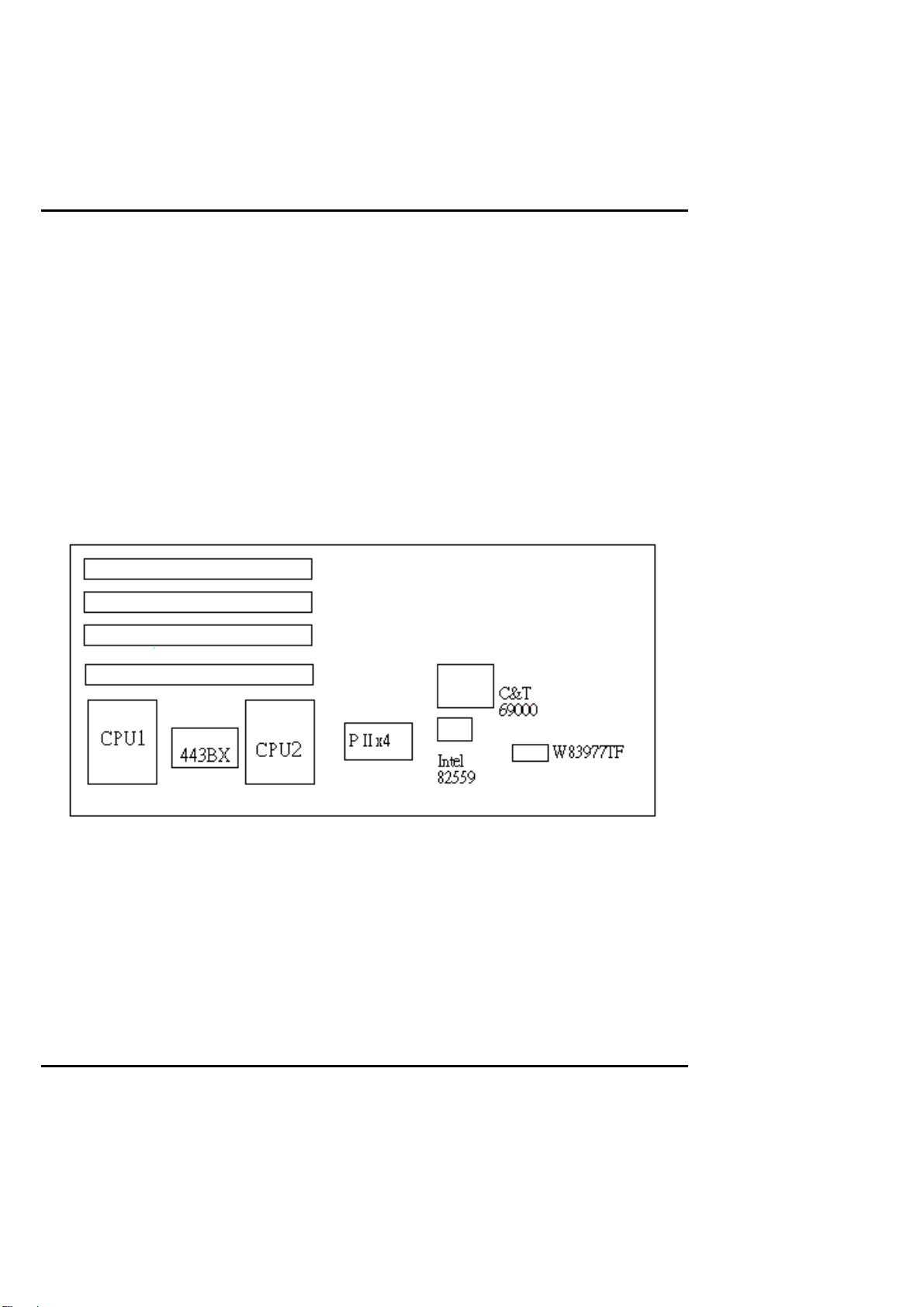
Your system memory is provided by DIMM's (Dual In-line Memory Modules) on the
CPU board. The CPU board contains four memory banks: Bank 0, 1, 2, 3,
corresponds to connector DIMM1, DIMM2, DIMM3 and DIMM4.
The table below shows possible DIMM configurations for the memory banks.
You can also use the DIMM with parity check. The ECC (Error Checking and
Correction) could be turned on if parity DIMMS are used. The ECC will correct
one bit error and report two bit errors. Please be noted that the PEAK 6320A only
supports the SDRAM.
DIMM 1 DIMM 2 DIMM 3 DIMM 4 Total Memory
16M 16M 16M 16M 64MB
32M 32M Empty Empty 64MB
32M 16M 16M Empty 64MB
64M Empty Empty Empty 64MB
32M 32M 32M Empty 96MB
64M 32M Empty Empty 96MB
64M 64M Empty Empty 128MB
32M 32M 32M 32M 128MB
64M 64M 64M Empty 192MB
64M 64M 16M 16M 192MB
64M 64M 64M 64M 256MB
128M Empty Empty Empty 128MB
128M 128M Empty Empty 256MB
128M 128M 128M Empty 384MB
128M 128M 128M 128M 512MB
256M Empty Empty Empty 256MB
256M 256M Empty Empty 512MB
256M 256M 256M Empty 768MB
256M 256M 256M 256M 1GB
Capability Expanding 3-
1
Page 27
Peak 632A User's Guide
Installing DIMM
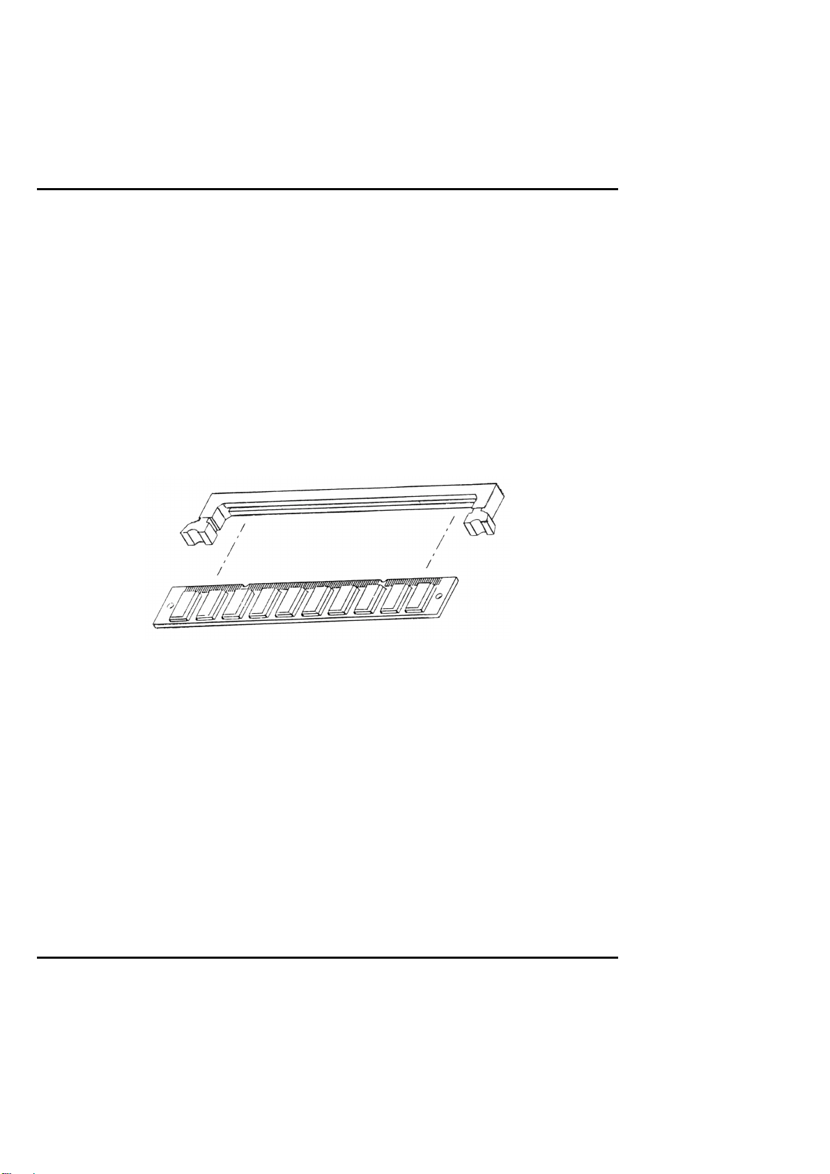
To install the DIMM , first make sure the two handles of the DIMM socket are in the
penposition, i.e. the handles stay outward. Slowly slide the DIMM modules
along the plastic guides in the both ends of the socket. Then press the DIMM
module down right into the socket, until a click is heard. That means the two
handles automatically locked the memory modules into the right position of the
DIMM socket as Figure 3-1 shows. To take away the memory module, just push the
both handles outward , the memory module will be ej ected by the mech anism in the
socket.
Figure 3-1 Install DIMM
Capability Expanding 3-
2
Page 28
Peak 632A User's Guide
3-2 Cache Memory
Since the second level cache has been embedded into the Pentium II CPU. You do
not have to take care of either SRAM chips or SRAM mod ules. The built-in second
level cache in the Pentium II yields much higher performance than the external ones.
The cache size in the Pentium II CPU is either 256KB or 512KB. Normally, for
workstation and server applications, th e 256KB version is good enou gh. However,
if your system is for heavy duty applications, the 512kB version will help a lot.
Specifically for our Pentium II based SBC, the Pentium II has another version
provide much better data security if combined with the DRAM ECC, please check
with your vendor for various Pentium II models.
Figure 3-2 Memory Banks
The level 2 cache of the Peak 6320A is built in the Celeron/Pentium III current
Celerons have 128 KB on die L2 Cache which is very fast because it’s running at the
CPU speed. Fut ure Celerons/Pentium III might be upgr aded to 256 KB L2 Cache.
Capability Expanding 3-
3
Page 29
Peak 632A User's Guide
3-3 Change CPU
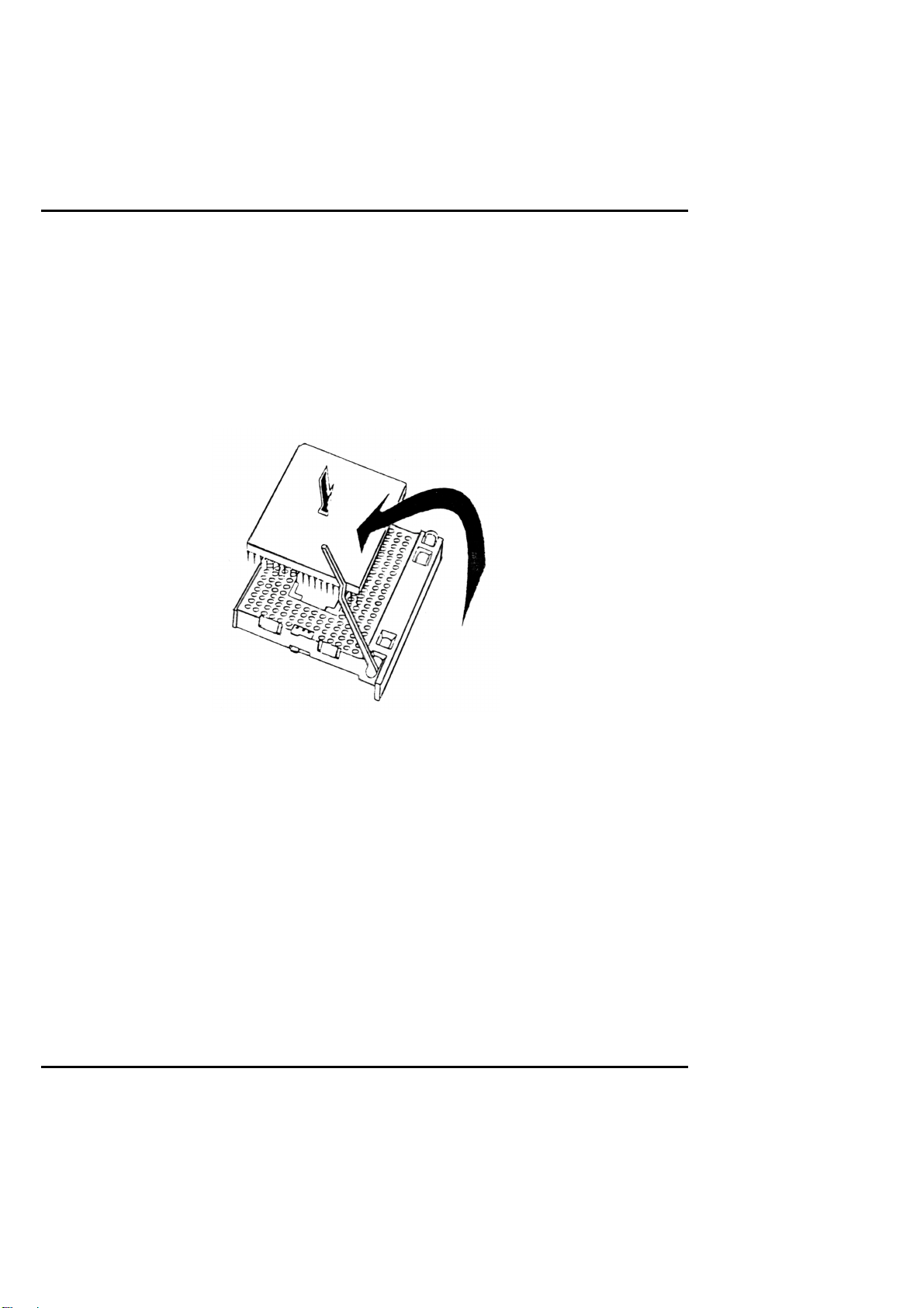
To change the CP U, pull the handling bar of the socket upward to the other end to
loosen the socket's openings. Carefully lift the existing CPU up to remove it from
the socket.
Figure 3-3 Removing CPU
Capability Expanding 3-
4
Page 30
Peak 632A User's Guide
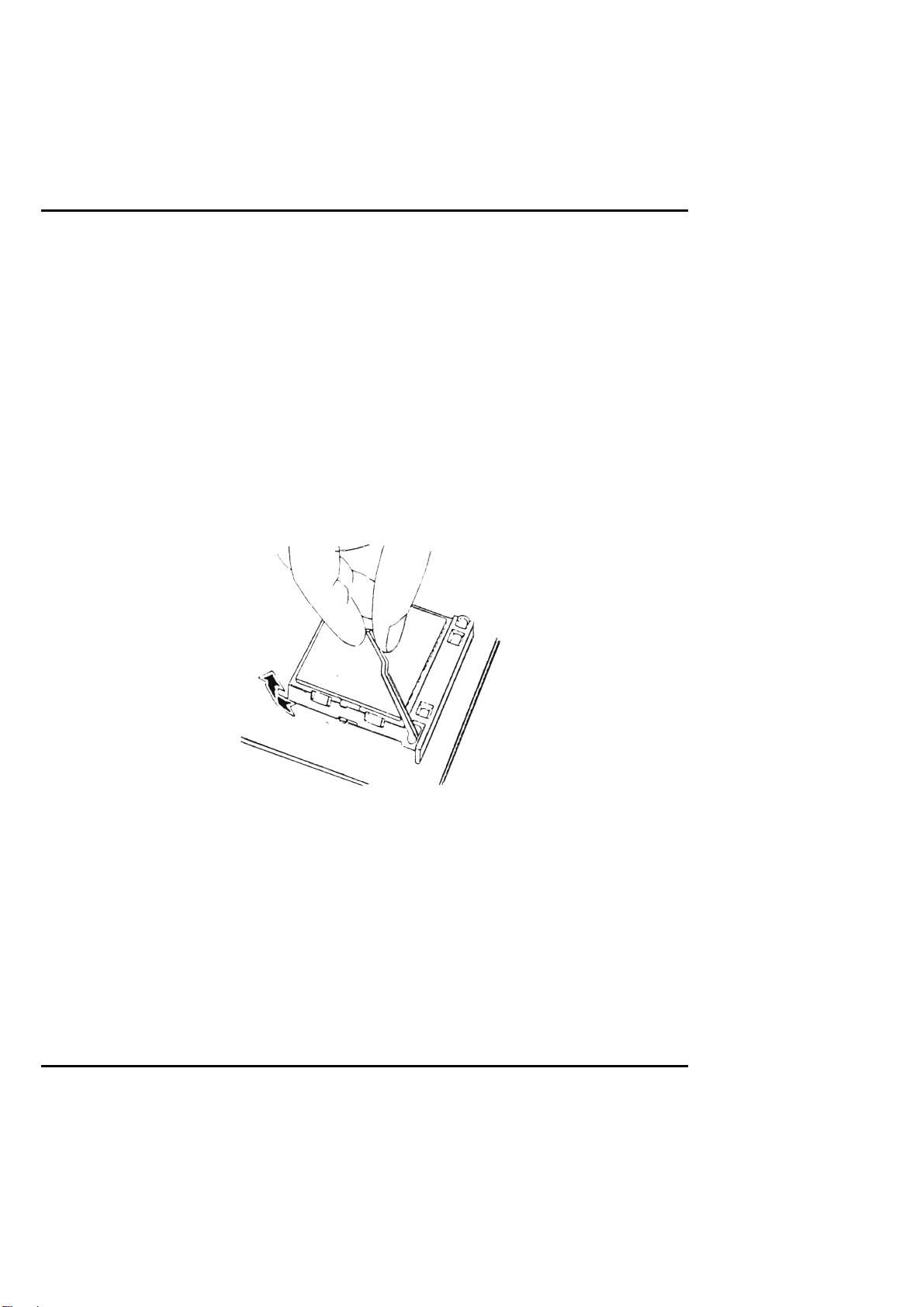
Place the new CPU on the mid dle of the socket, orienting its beveled corner to line up
with the socket's beveled corner. Make sure the pins of the CPU fit evenly to the
socket openings. Replace the handling bar to fasten the CPU to the socket. Be
sure to re-arrange the jumper setting for the correct external clock (66MHz or
100MHz) by (SW1.3) (SW1.4).
Figure 3-4 Installing CPU
Capability Expanding 3-
5
Page 31

PEAK 632A User Guide
Chapter 4
AWARD BIOS Setup
Award's BIOS ROM has a built-in Setup program that allows users to modify the basic
system configuration. This type of information is stored in battery-backed RAM (CMOS
RAM) so that it retains the Setup information when the power is turned off.
Entering Setup
Power on the computer and press <Del> immediately will allow you to enter Setup. The
other way to enter Setup is to power on the computer, when the below message appears
briefly at the botto m of the screen during the POST (Power On Self Test), press <Del> key
or simultaneously press <Ctrl> , < Alt> , and <Esc> k eys.
TO ENTER SETUP BEFORE BOOT PRESS <CTRL-ALT-ESC> OR <DEL> KEY
If the message disappears before you respond and you still wish to enter Setup, restart the
system to try again by turning it OFF then ON o r pressing the "RESET " button on the system
case. You may also restart by simultaneo usly pressing <C trl>, <Alt>, and <D elete> keys. I f
you do not press the key s at the correct time and the system does not bo ot, an error messag e
will be displayed and yo u w ill again be asked to ,
PRESS <F1> TO CONTINUE, <CTRL-ALT-ESC> OR <DEL> TO ENTER SETUP
BIOS Setup 4-
1
Page 32

PEAK 632A User Guide
Control Keys
Up arrow Move to previous item
Down arrow Move to next item
Left arrow Move to the item in the left hand
Right arrow Move to the item in the right hand
Esc key Main Menu -- Quit and not save changes into CMOS
Status Page Setup Menu and Option Page Setup Menu -- Exit current page
and return to Main Menu
PgUp / ”
key
PgDn /
“
key
−
F1 key General help, only for Status Page Setup Menu and Option Page Setup Menu
(Shift)F2 key Change color from total 16 colors. F2 to select color forward, (Shift) F2 to
F3 key Reserved
F4 key Reserved
F5 key Restore the previous CMOS value from CMOS, only for Option Page Setup
F6 key Load the default CMOS value from BIOS default table, only for Option Page
F7 key Load the Setup default , only for Option Page Setup Menu
F8 key Reserved
F9 key Reserved
F10 key Save all the CMOS changes, only for Main Menu
Increase the numeric value or make changes
Decrease the numeric value or make changes
select color backward
Menu
Setup Menu
BIOS Setup 4-
2
Page 33

PEAK 632A User Guide
Getting Help
Main Menu
The on-line desc r ipt ion of t he hi ghl ight ed s etup f unc t ion i s di s played at the bot tom
of the screen.
Status Page Setup Menu/Option Page Setup M enu
Press F1 to pop up a small help window that describes the appropriate keys to use
and the possible selections for the highlighted item. To exit the Help Window press
<F1> or <Esc>.
BIOS Setup 4-
3
Page 34
PEAK 632A User Guide
The Main Menu
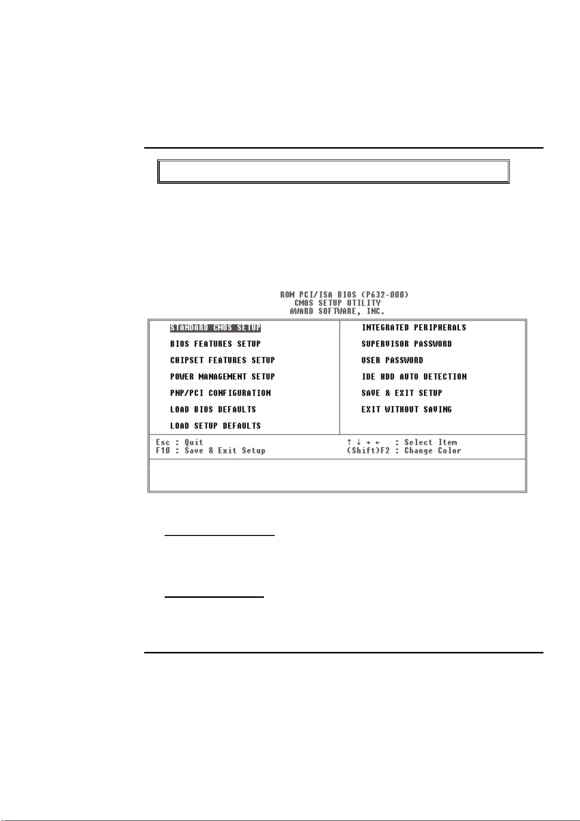
Once you enter Award BI OS C MOS S etup Utility, the Main Menu(Figure 1) will appear on
the screen. The Main Menu allows you to select from ten setup functions and two exit
choices. Use arrow key s to select among the items and press <Enter> to accept or enter the
sub-menu.
Standard CMOS setup
This setup page includes all the items in a standard compatible BIOS . See Page 4-7 to Page
4-10 for details.
BIOS features setup
This setup page includes all the items of Award special enhanced features. See Page 4-11 to
Page 4-15 for details.
BIOS Setup 4-
4
Page 35

PEAK 632A User Guide
Chipset features set up
This setup page includes all the items of chipset special features. See Page 4-16 to Page
4-20 for details.
Power Management se tup
This category determines how much power consumption for system after selecting below
items. Default value is Disable. See Pag e 4- 21 to Page 4-25 for details.
PNP/PCI CONFIGURATION
This category specif ies the assignm ent o f all the IRQ and DMA .
See Page 4-26 to Page 4-27 for details.
Load BIOS defaults
BIOS defaults indicates the most appropriate value of the system parameter which the
system would be in minimum performance. The OEM manufacturer may change the
defaults through MODBI N befo re the binary im age burn into the RO M.
Load setup defaults
Chipset defaults indicates the values required by the sy stem for the maxim um performance.
The OEM manuf acturer m ay change to defaults thro ugh MO DBI N bef ore the binary image
burn into the ROM.
Integrated Peripheral s System Environment
This category allo ws you to set up all the on board I/O contro llers like IDE, SCSI , FDC, etc,.
See Page 4-28 to Page 4-30
Password Setting
Change, set, or disable password of supervisor or user. It allows you to limit access to the
system and Setup, or just to Setup. See Page 4-31 for details.
BIOS Setup 4-
5
Page 36

PEAK 632A User Guide
IDE HDD auto detection
Automatically co nfig ure hard disk parameters. See Page 4-32 to Page 4-35.
Save & Exit Setup
Save CMOS value chang es to CMOS and exit setup.
Exit without saving
Abandon all CMOS value changes and exit setup.
BIOS Setup 4-
6
Page 37
PEAK 632A User Guide
Standard CMOS Setup Menu
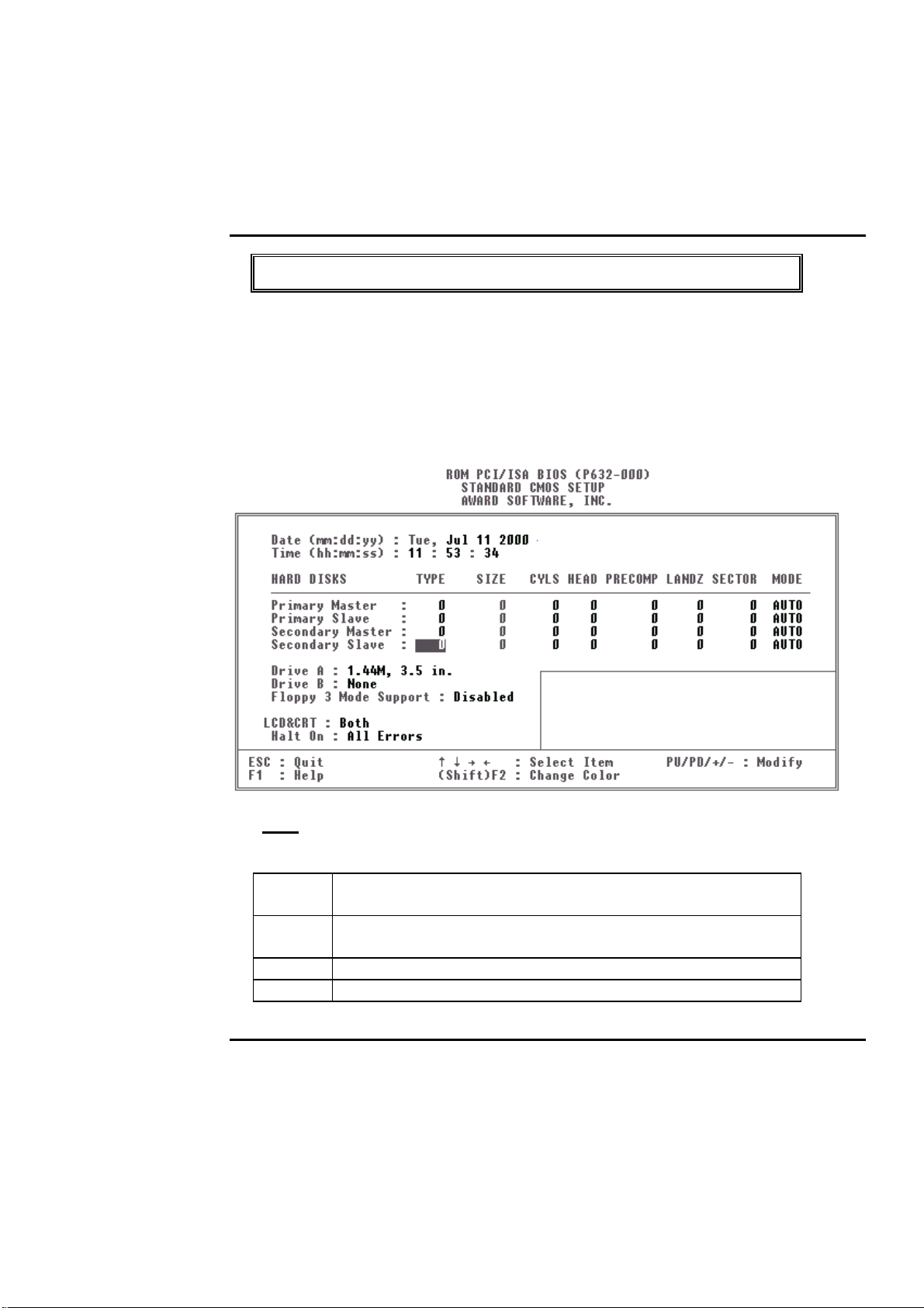
The items in Standard CMOS Setup Menu are divided into 10 categories. Each category
includes no , one or mo re than o ne setup items. Use the arro w key s to hig hlight the item and
then use the <PgUp> or <PgDn> k eys to select the value you want in each item.
Figure 2 Standard CM OS Setup Menu (Support E nhanced IDE)
Date
The date format is <day>, <date> <month> <year>. Press <F3> to show the calendar.
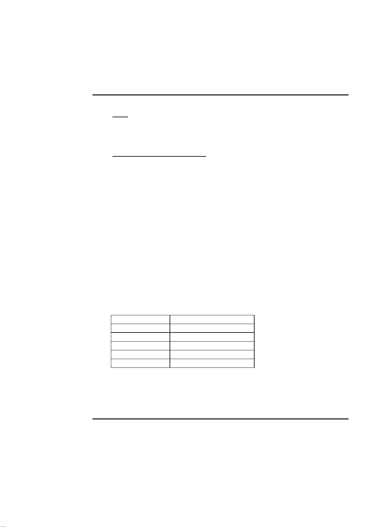
Day The day of w eek, from Sun to Sat, determined by the BIOS, is read
only
date The date, from 1 to 31 (or the maximum allowed in the month), can
key in the numerical / f unctio n key
month The month, Jan through Dec
year The year, depend on the year of BIOS
BIOS Setup 4-
7
Page 38
PEAK 632A User Guide
Time
The time format is <hour> <minute> <second>. which accepts both function key or
numerical key The time is calculated based on the 24-hour military-time clock. For
example, 1 p.m. is 13:00:00.
Primary Master/Pri mary Slave
The categories identify the types o f drives that have been installed in the computer. There
are 45 predefined types and 2 user definable types are for Enhanced I DE BI OS. Ty pe 1 to
Type 45 are predefined. Type User is user-definable.
Press PgUp/<+> or PgDn/<−> to select a numbered hard disk ty pe or type the number and
press <Enter>. Note that the specifications of y our drive must match w ith the drive table.
The hard disk will not work properly if you enter improper information for this category.
If y our hard disk drive ty pe is not matched o r listed, y ou can use Type User to define your
own drive type manually.
If y ou select Ty pe User, related inf ormatio n is asked to be entered to the follo w ing items.
Enter the information directly from the keyboard and press <Enter>. This information
should be provided in the documentation from your hard disk vendor or the system
manufacturer.
If the controller of HDD interface is ES DI, the selection shall be ype 1
If the controller of HDD interface is SCSI , the selection shall be one
If the controller of HDD interface is CD-ROM, the selection shall be one
CYLS. number of cy linders
HEADS number o f heads
PRECOMP write precom
LANDZ ONE landing zone
SECTORS number of sectors
MODE HDD access mode
If a hard disk has not been installed select NONE and press <Enter>.
BIOS Setup 4-
8
Page 39
PEAK 632A User Guide
Drive A type/Drive B type
The category identifies the ty pes of floppy disk drive A or drive B that have been installed in
the computer.
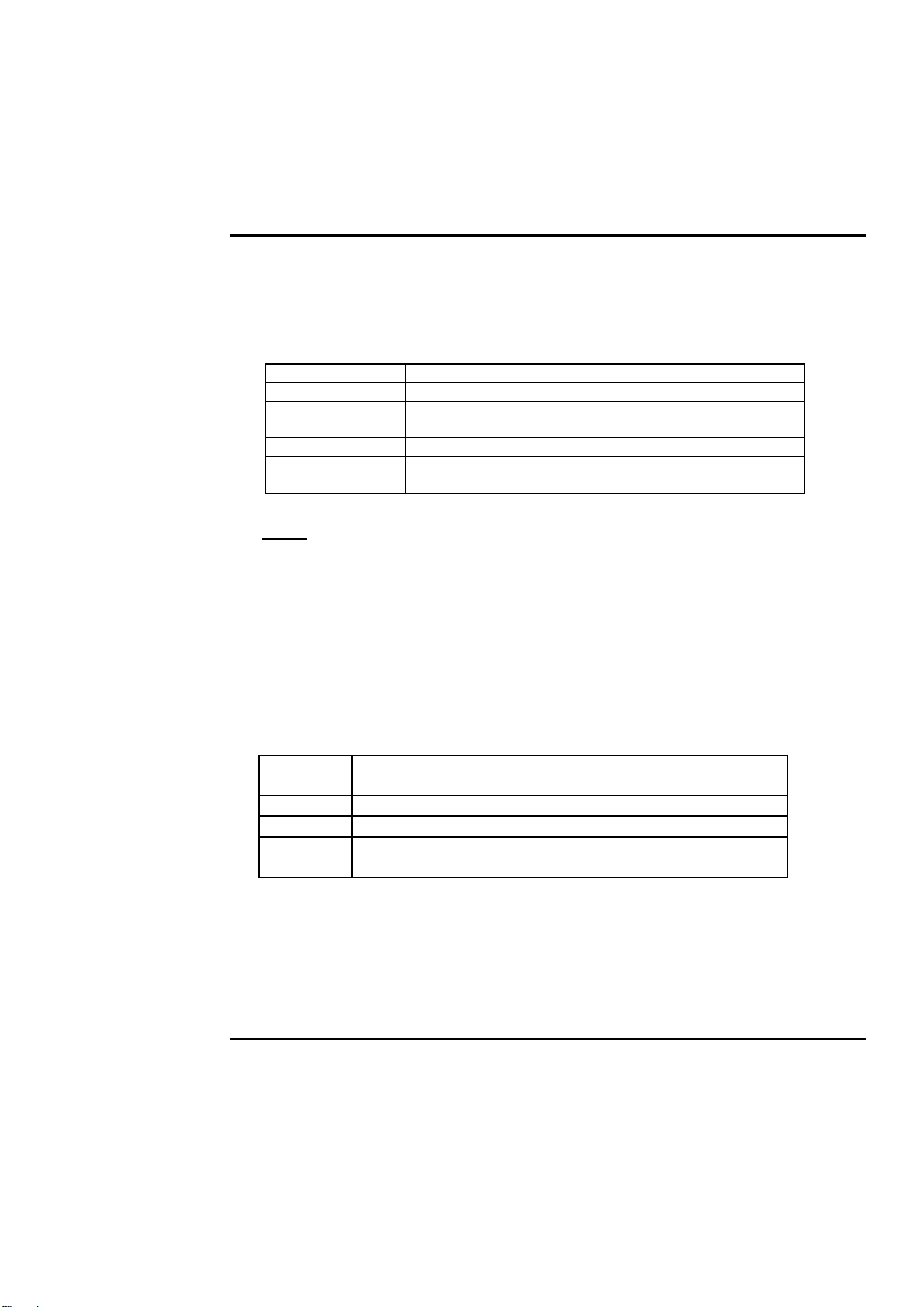
None N o floppy drive installed
360K, 5.25 in 5-1/4 inch PC-type standard drive; 360 kilobyte capacity
1.2M, 5.25 in 5-1/4 inch AT-type high-density drive; 1.2 megabyte
capacity
720K, 3.5 in 3 -1/2 inch double-side d drive; 720 kilobyte capacity
1.44M, 3.5 in 3-1/2 inch double -sided drive; 1.44 megabyte capacity
2.88M, 3.5 in 3-1/2 inch double -sided drive; 2.88 megabyte capacity
Video
The category selects the type of adapter used for the primary system monito r that must match
your video display card and monitor. Although secondary monitors are supported, you do
not have to select the type in Setup.
You have two ways to boot up the system:
1. When VGA as primary and monochrome as secondary, the selection of the
video tape is GA Mode
2. When monochrome as primary and VGA as secondary, the selection of the
video type is onochrome Mode
EGA/VGA
Enhanced Graphics Adapter/Video Graphics Array. For EGA,
VGA, SEGA, or PGA monitor adapters.
CGA 40
CGA 80
MONO
Color Graphics Adapter, pow er up in 40 colum n mo de
Color Graphics Adapter, po wer up in 80 column mode
Monochrome adapter, includes high resolution monochrome
adapters
BIOS Setup 4-
9
Page 40

PEAK 632A User Guide
Error Halt
The category determines whether the com puter will stop if an error is detected during power
up.
No errors Whenever the BIOS detects a non-fatal error the system
will be stopped and you will be prompted.
All errors The system boot will not be stopped for any error that
may be detected.
All,But
Keyboard
The system boot will not stop for a keyboard error; it will
stop for all other errors.
All, But Diskette The s ystem boot will not stop for a disk error; it will stop
for all other errors.
All, But Disk/Key The system boot will not stop for a keyboard or disk error;
it will stop for all othe r e rro rs.
Memory
The category is display-only which is determined by POST (Power On Self Test) of the
BIOS.
Base Memory
The POST of the BIOS will determine the amount of base (or conventional)
memory installed in the system. The value of the base memory is typically 512K
for systems w ith 512K mem ory installed on the motherbo ard, or 640K fo r systems
with 640K or more mem o ry installed on the motherboard.
Extended Memory
The BIOS determines how much extended memory is present during the POST.
This is the amount of memory located above 1MB in the CPU's memory address
map.
Other Memory
This refers to the memory located in the 640K to 1024K address space. This is
memory that can be used for different applications. DOS uses this area to load
device drivers to k eep as much base memory free for application program s. M o st
use for this area is Shadow RAM.
BIOS Setup 4-
10
Page 41
PEAK 632A User Guide
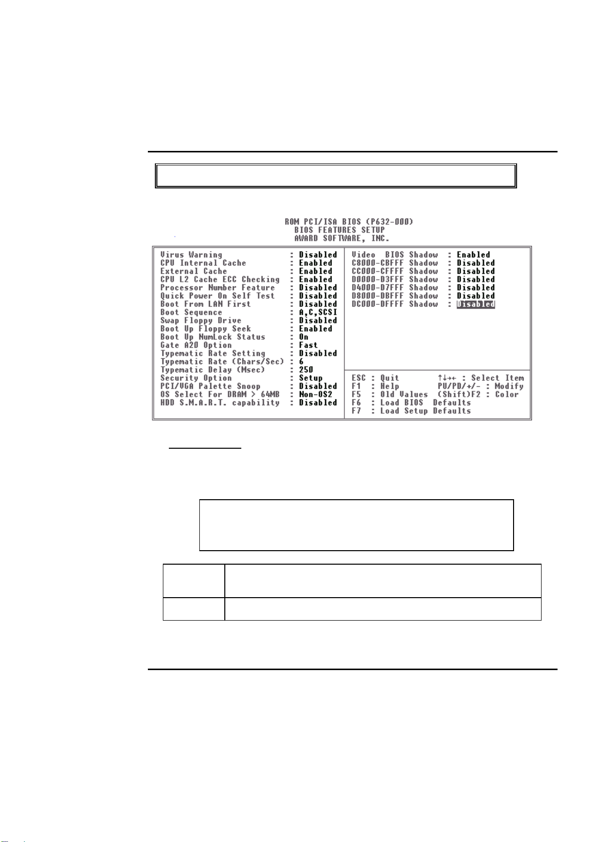
BIOS Features Setup Menu
Virus Warning
This category flashes on the screen. During and after the system boots up, any attempt to
write to the boot sector or partition table of the hard disk drive will halt the system and the
following error message w ill appear, in the m ean time, y o u can run an anti-v irus program to
locate the problem.
! WARNING !
Disk boot sector is to be modified
Type "Y" to accept write or "N" to abort write
Award Soft ware, Inc.
Enabled Activates automatically when the system boots up causing a warning
message to appear when anything attempts to access the boot sector or
hard disk partition tabl e.
Disabl ed No warning message to appear when anything attempts to access the
boot sector or hard disk partition table.
N
ote: This function is available only for DOS and other OSes that do not trap INT13.
BIOS Setup 4-
11
Page 42
PEAK 632A User Guide
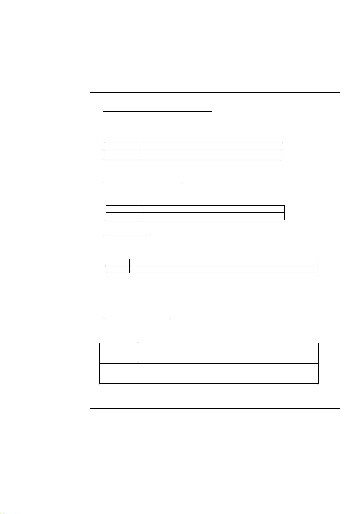
CPU Internal Cache/External Cache
These two categories speed up memory access. However, it depends on CPU/chipset design.
The default value is Enable. If your CPU without Internal Cache then this item PU
Internal Cache” will not be show.
Enabled Enable cache
Disabled Disable cache
Quick Power On Self Test
This category speeds up Po wer On Self Test (POST) after you power on the com puter. If it
is set to Enable, BIOS will shorten or skip some check items during POS T.
Enabled Enable quick POST
Disabled Normal POST
Boot Sequence
This category determines which drive com puter searches first for the disk operating system
(i.e., DOS). Default value is A,C.
C,A System will firs t search for hard disk driv e then floppy disk drive.
A,C System will fi rst search for f loppy disk drive then hard disk driv e.
Note: This function is only available for IDE type. For SCSI type is always boot
from A.
Boot Up Floppy Seek
During POST, BIOS will determine if the floppy disk drive installed is 40 or 80 tracks.
360K type is 40 track s while 760K, 1.2M and 1.44M are all 80 tracks.
Enabled BIOS searches for floppy disk drive to determine if it is 40 or 80
tracks. Note that BIOS can not tell from 720K, 1.2M or 1.44M drive
type as they are all 80 tracks.
Disabled BIOS will not search for the type of floppy disk drive by track
number. Note that there will not be any warning message if the
drive install ed is 360K.
BIOS Setup 4-
12
Page 43
PEAK 632A User Guide
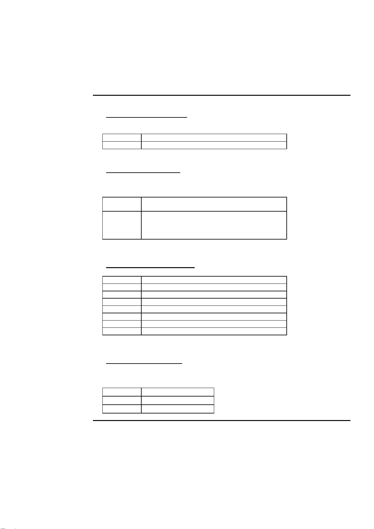
Boot Up NumLock Status
The default value is On.
On Keypad is number keys
Off Keypad is arrow keys
Typematic Rate Setting
This determines the typematic r ate.
Enabled Enable typematic rate and typematic delay
programming
Disabled Disable typematic rate and typematic delay
programming. The system BIOS will use default
value of this 2 items and the def ault is contr olled by
keyboard.
Typematic Rate (Chars/Sec)
6 6 charac ters per second
8 8 charac ters per second
10 10 characters per second
12 12 characters per second
15 15 characters per second
20 20 characters per second
24 24 characters per second
30 30 characters per second
Typematic Delay (Msec)
When holding a key, the time between the fi rst and second character displayed.
250 250 msec
500 500 msec
750 750 msec
BIOS Setup 4-
13
Page 44
PEAK 632A User Guide
1000 1000 msec
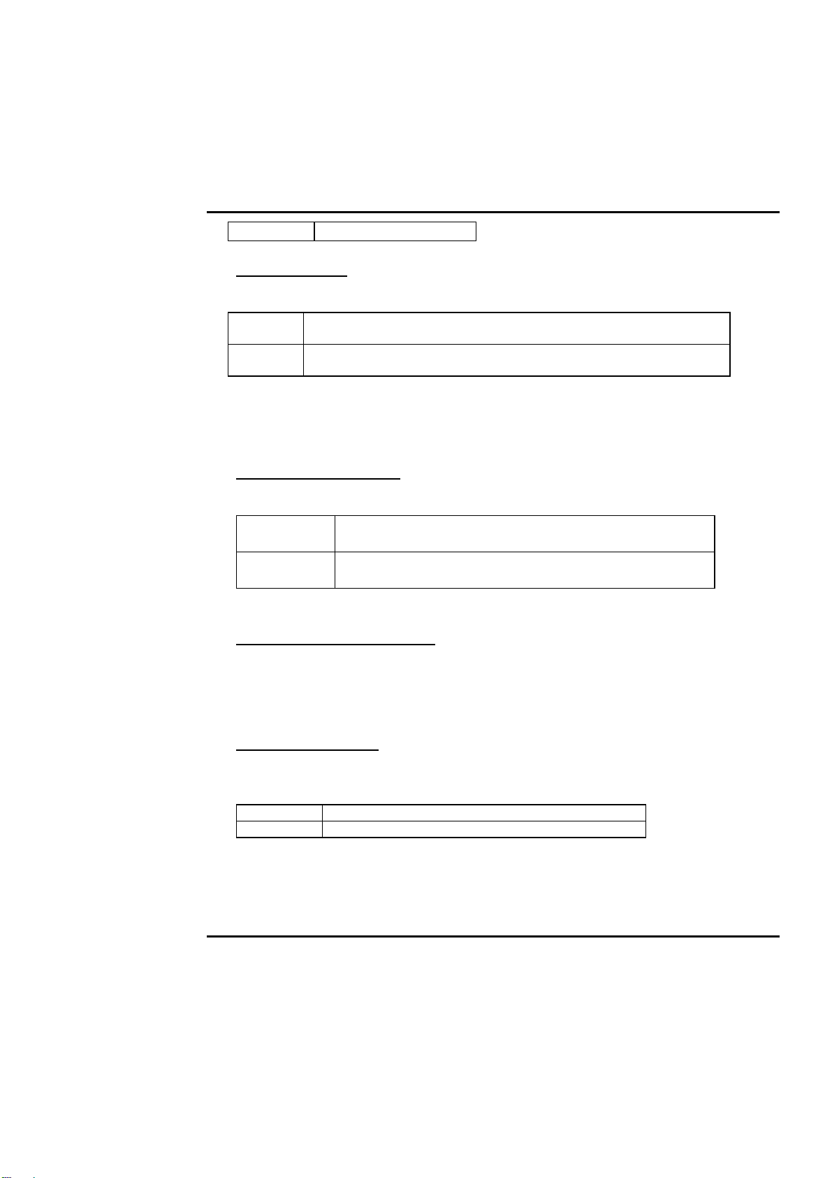
Security Option
This category allows you to limit access to the system and Setup, or just to Setup.
System The system will not boot and access to Setup will be denied if the
correct password is not entered at the prompt.
Setup The system will boot, but access to Setup will be denied if the correct
password is not entered at the prom pt.
Note: To disable security, select PASSWORD SETTING at Main Menu and then you will
be asked to enter password. Do not type anything and just press <Enter>, it will disable
security. Once the security is disabled, the system will boo t and you can enter Setup freely.
PCI/VGA Palette Snoop
It determines whether the MPEG ISA/VESA VGA Cards can work with PCI/VGA or not.
Enabled When PCI/VGA working with MPEG ISA/VESA VGA
Card.
Disabled When PCI/VGA not working with MPEG ISA/VESA
VGA Card.
OS Select for DRAM > 64MB
This segment is specifically created for OS/2 when DRAM is larger than 64MB. If your
operating system is OS/2 and DRAM used is larger the 64MB, you have to select S 2
otherwise, non-OS2, default is NON-OS2.
Video BIOS Shadow
It determines whether video BIOS will be copied to RAM, however, it is optional from
chipset design. Video Shadow will increase the vi deo speed.
Enabled Video shadow is enabled
Disabl ed Vi deo shadow is dis abled
BIOS Setup 4-
14
Page 45

PEAK 632A User Guide
C8000 - CFFFF Shadow /D8000 - DFFFF Shadow
These categories determine whether optional ROM will be copied to RAM by 16K byte or
32K byte per/unit and the siz e depends on chipset.
Enabled Optional shadow is enabled
Disabl ed Optiona l shadow i s disabled
Note: 1. for C8000-DFFFF option-ROM on PCI BIOS , BIOS will automatically
enable the shadow RAM. User do es no t have to select the item .
2. IDE second channel control:
Enable :enable secondary IDE port and BIOS will assign IRQ15 for this
port.
Disable: disable secondary IDE port and IRQ15 is available for other
device.
The item is optional only for PCI BIOS.
3. Some of the sound cards have an onboard CD- ROM controller
which uses IDE Secondary Port. In order to avoid PCI IDE conflict, the IDE
secondary channel co ntrol has to select isablethen CD- ROM can work.
BIOS Setup 4-
15
Page 46
PEAK 632A User Guide
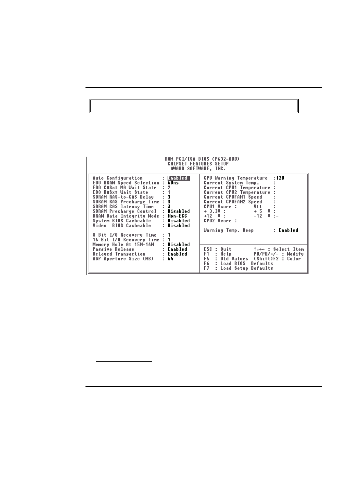
Chipset Features Setup Menu
Since the features in this section are related to the chipset in the CPU board and all are
optimized, y ou are not recom mended to change the default settings in the setup table, unless
you know very detailed of the chipset features.
This section describes features of the Intel 440BX PCIset. If your system contains a different
chipset, this section will bear little resemblance to what you see on your screen.
ADVANCED OPTIONS. The parameters in this screen are for system designers, service
personnel, and technically competent users only . Do not reset these values unless you understand
the consequences of yo ur changes.
NOTE: This chapter describes all f ields o f f ered by A w ard S of tware in this screen. Your system
board designer may omit or modify some fields.
Auto Configuration
Auto Configuratio n selects predetermined o ptimal values of chipset parameters. When
Disabled, chipset parameters revert to setup information stored in CMO S. Many fields in this
screen are not available when Auto Conf iguration is Enabled.
BIOS Setup 4-
16
Page 47

PEAK 632A User Guide
The Choice: Enabled, D isabled.
BIOS Setup 4-
17
Page 48

PEAK 632A User Guide
EDO DRAM Speed Selection
The DRAM timing is co ntrolled by the DRA M Timing Registers. The timings program med
into this register are dependent on the system design. Slo wer rates may be required in certain
system designs to support loose layouts or slower memory.
50ns DRAM Timing Type.
60ns DRAM Timing Type.
EDO CASx# MA Wait State
You could select the timing control ty pe of ED O D RA M CAS M A (memo ry address bus).
The choice: 1, 2.
EDO RASx# MA Wait State
You could select the timing control ty pe of ED O D RA M RAS M A (memo ry address bus).
The choice: 1, 2.
SDRAM RAS-to-CAS Delay
You can select RAS to CA S D elay time in HCLK s o f 2/2 o r 3/3. T he system board designer
should set the values in this field, depending o n the D R AM installed. D o no t chang e the
values in this field unless you change specific ations of the installed DRAM or the installed
CPU. The Choice: 2, 3.
SDRAM RAS Precharge Time
Defines the length of time fo r Row Address S trobe is allowed to precharge. The Choice: 2, 3
SDRAM CAS latency Time
You can select CAS latency time in HCLKs o f 2/2 or 3/3. The sy stem board designer should
set the values in this field, depending on the D RA M installed. Do no t change the v alues in
this field unless you change specificatio ns o f the installed DRA M o r the installed CPU.T he
choice: 2, 3.
DRAM Data Integrity Mode
BIOS Setup 4-
18
Page 49

PEAK 632A User Guide
Select Parity or ECC (error-correcting code), according to the ty pe of installed DRAM. The
Choice: Non-ECC, ECC.
BIOS Setup 4-
19
Page 50

PEAK 632A User Guide
System BIOS Cacheable
Select Enabled allows caching of the system BIOS R OM at F000h-FFFFFh, resulting in
better system perform ance. Ho w ev er, if any program writes to this mem ory area, a system
error may result.
Enabled BIOS access cached
Disabled BIOS access no t cached
Video BIOS Cacheable
Select Enabled allows caching of the video BIOS ROM at C0000h-F7FFFh, resulting in
better video performance. Ho w ev er, if any prog ram w rites to this mem o ry area, a system
error may result.
Enabled Video BIOS access cached
Disabled Video BIOS access not cached
Video RAM Cacheable
Select Enabled allows caching o f the v ideo RA M , resulting in better system performance.
However, if any program writes to this memo ry area, a system error may result.
8 Bit I/O Recovery Time
The recovery tim e is the length oftime, measured in CPU clocks, which the system will delay
after the completion of an input/o utput request. T his delay takes place because the CPU is
operating so much faster than the input/output bus that the CPU must be delayed to allow for
the completio n of the I /O. T his item allow s you to determine the recovery time allowed fo r 8
bit I/O. Choices are fro m NA, 1 to 8 CPU clocks.
16 Bit I/O Recovery Time
This item allows you to determine the recovery time allow ed for 16 bit I/O. Cho ices are from
NA, 1 to 4 CPU clocks.
Memory Hole At 15M-16M
In order to improve performance, certain space in memory can be reserved for ISA cards.
This memory must be mapped into the mem o ry space below 16 MB.
Enabled Memory hole supported.
BIOS Setup 4-
20
Page 51

PEAK 632A User Guide
Disabled Memory hole not supported.
Passive Release
When Enabled, CPU to PC I bus accesses are allow ed during passive release. Otherwise, the
arbiter only accepts ano ther PCI master access to local DRAM. The choice: Enabled,
Disabled.
Delayed Transaction
The chipset has an embedded 32-bit po sted write buff er to support delay transactions cy cles.
Select Enabled to support compliance with PCI specification version 2.1. The choice:
Enabled, Disabled.
AGP Aperture Size (MB)
Select the size of the Accelerated Graphics Po rt (AGP) aperture. The aperture is a portion of
the PCI memory address range dedicated for graphics memory address space. Host cycles
that hit the aperture range are forwarded to the A GP without any translation. See
www.agpforum.org
for AGP information.
The choice: 4, 8, 16, 32, 64, 128, 256
Auto Detect DIMM/ PCI Clk
This item auto detect the clock g enerator. The unused pins of D IMM/ PCI Clk are disabled.
The amplitudes of the radiated electromagneti c emissions are reduced. Choices: Enabled,
Disabled.
Spread Spectrum Modulat ed
The Clock Generator g enerates a clock that is f requency mo dulated in order to increase the
bandwidth that is occupies. By increasing the bandwidth of the fundamental and its
harmonics, the amplitudes of the radiated electrom agnetic emissio ns are reduced.
Choices: Enabled, Disabled.
BIOS Setup 4-
21
Page 52
PEAK 632A User Guide
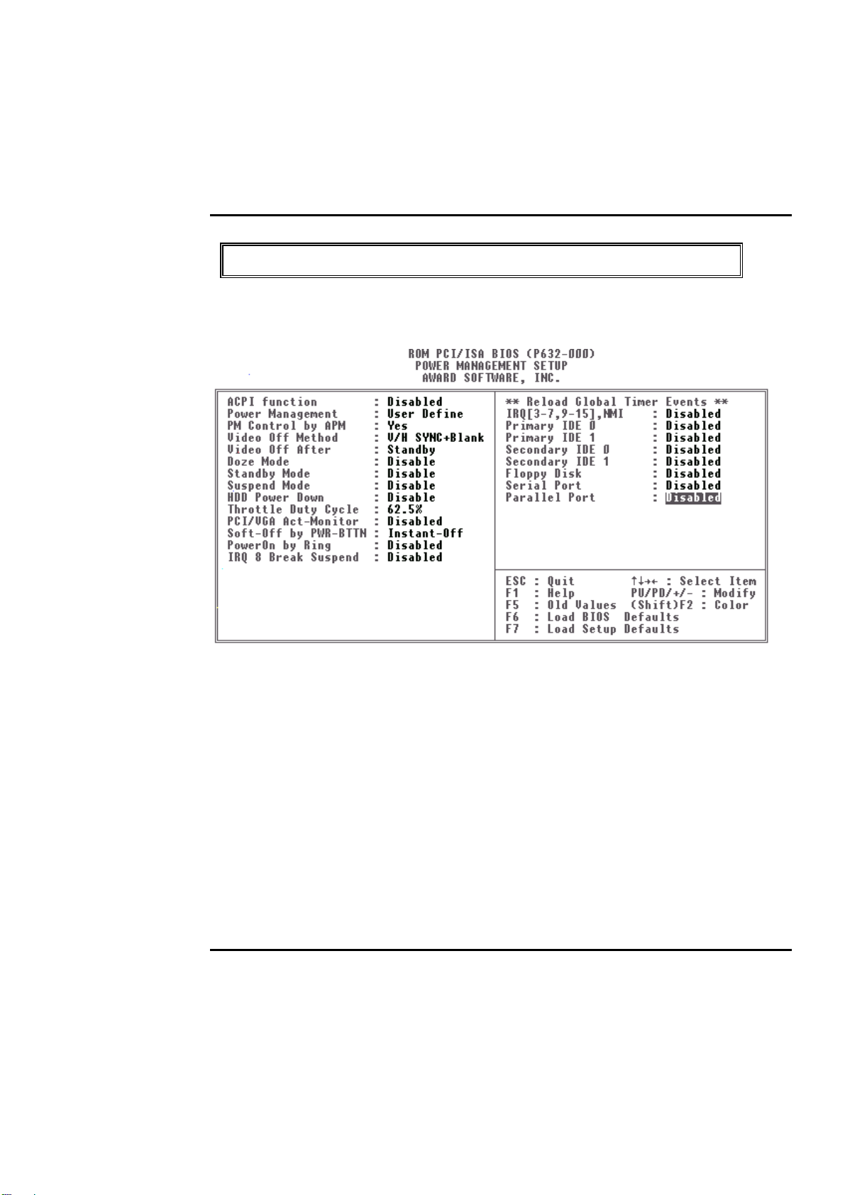
Power Management Setup
The Power manag ement setup w ill appear o n your screen like this:
BIOS Setup 4-
22
Page 53
PEAK 632A User Guide
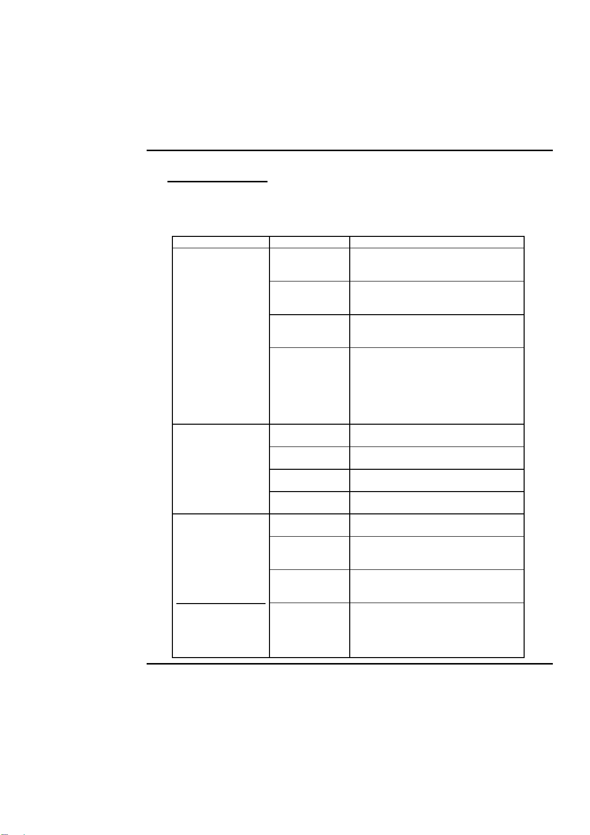
Power Management
This category determines how much power consumption for system after selecting below
items. Default value is Disable. The following pages tell you the options of each item &
describe the meanings of each options.
Item Options Descriptions
A.Power
Management
1. Disable Global Power Management will be
disabled
2. User Define Users can configur e their own power
management
3. Min Saving Pre-defined timer values ar e used
such that all timer s are i n thei r M AX
value
4. Max Saving Pre-defined tim er values ar e used
such that all timers MIN value
B. Video Off Option
C. Video Off
Method
BIOS Setup 4-
1. Always On System BIOS will never turn off the
screen
2.
Suspend->Off
3. Susp,
stby->Off
4. All Modes
->Off
1. Blank Screen The system BIOS will onl y blanks off
2. V/H SYN
C+Blank
3. DPMS
Supported
Screen off when system i s in
SUSPEND mode
Screen off when system i s in
STANDBY or SUSPEND mode
Screen off when system is i n DOZE,
STANDBY or SUSPEND mode
the screen when disabling vi deo
In addition to (1), BIOS will also turn off
the V-SYNC & H-SYNC si gnal s
from VGA cards to m onitor
This function is enabled f or onl y the
VGA card supporting DPMS
Note: Green monitors
detect the V/H
SYNC signals to
turn off its electron
gun
23
Page 54
PEAK 632A User Guide
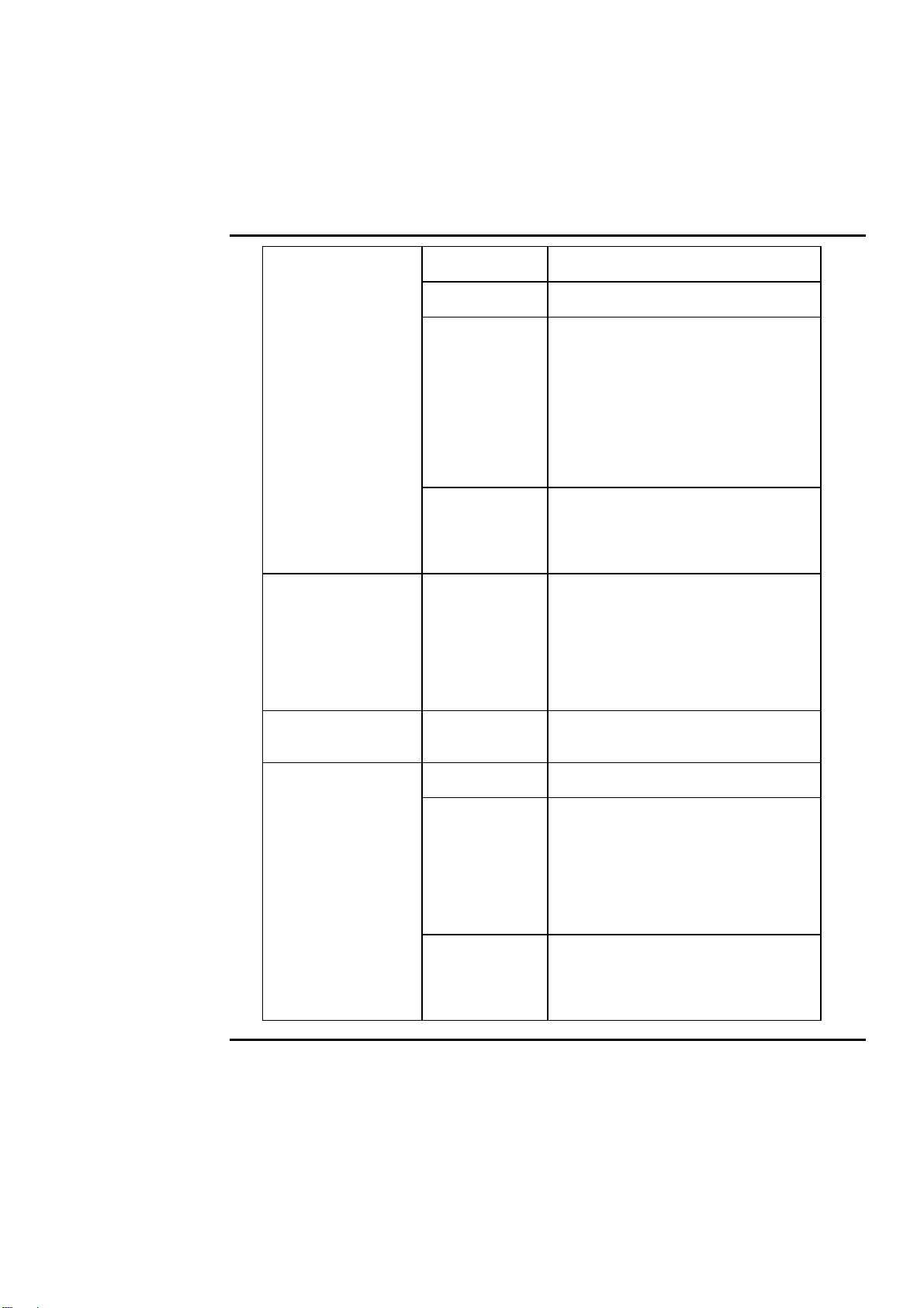
D. Switch Function 1. Break The External Sus pend Switch i s
reak”
2. W ake The Exter nal Suspend Swi tch i s
ake”
E. Doze Speed(div
by)
Stdby speed (div
by)
F. Modem Use IRQ
G. Standby Mode
(*) Remark 1
2. 1 Min
2 Min
4 Min
6 Min
8 Min
10 Min
20 Min
30 Min
40 Min
1 Hr
1/8
2/8
3/8
4/8
5/8
6/8
7/8
8/8
3,4,5,7,9
4,10,11,NA
1. Disable System will never enter STANDBY
2. 10 sec
1 Min
10 Min
30 Min
1 Hour
2 Hour
20 Min
Defines the continuous idl e time
before the system enteri ng DOZE
mode.
if any item defined in ( J) is enabled &
active, DOZE timer will be reloaded
Note: Normally,STANDBY
mode puts the system
into low speed or 8
MHz, screen may be
off depend on (E)
System full speed could be div ided by
the optional integers, the bigger the
number the slower the speed under
Doze or standby mode
For external modem, 3 or 4 will be
used for card type modem. It is up to
card definition. D efault i s 3.
mode
Defines the continuous idl e time
before the system enteri ng STANDBY
mode.
if any item defi ned in ( J) is enabled &
active, STANDBY timer will be
reloaded
Note: Normally,STANDBY
mode puts the system
into low speed or 8
MHz, screen may be
off depend on (E)
BIOS Setup 4-
24
Page 55
PEAK 632A User Guide
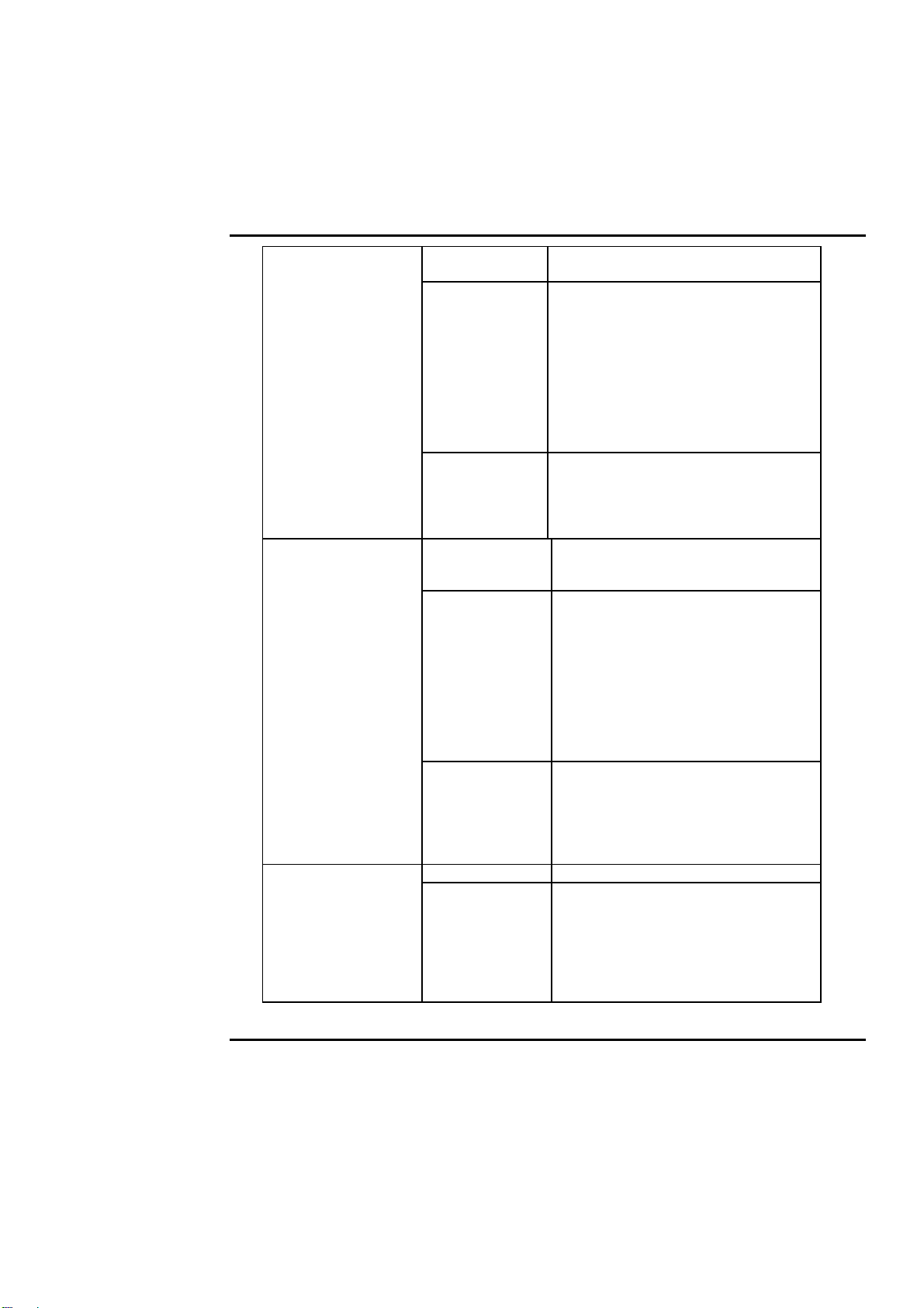
H. Doze
(*) Remark 1
I. Suspend Mode
(*) Remark 1
J. HDD Off 1. Disable HDD motor will not off
After: 2.10 Sec
1. Disable System will never enter STANDBY
mode
2. 1 Min
2 Min
4 Min
6 Min
8 Min
10 Min
20 Min
30 Min
40 Min
1 Hr
1. Disabl e System will never enter SUSPEND
2. 1 Min
2 Min
4 Min
6 Min
8 Min
10 Min
20 Min
30 Min
40 Min
1 Hr
1 Min
10 Min
30 Min
1 Hour
2 Hour
4 Hour
Defines the continuous idl e time
before the system enteri ng STANDBY
mode.
if any item defined in (J ) i s enabled &
active, STANDBY timer will be
reloaded
Note: Normally,STANDBY
mode puts the system
into low speed or 8
MHz, screen may be
off depend on (E)
mode
Defines the continuous idl e time
before the system entering SUSPEND
mode.
if any item defined in (J) is enabled &
active, SUSPEND timer will be
reloaded
Note: Normally,SUSPEND
mode puts the system
into low speed or 8
MHz, clock is
stopped, screen may
be off depend on (E)
Defines the continuous HDD idle time
before the HDD ent ering p ow e r saving
mode (motor of f)
BIOS Setup 4-
25
Page 56

PEAK 632A User Guide
K. VGA Activity 1. Disabled
IRQ3 (COM 2)
IRQ4 (COM 1)
IRQ5 (LPT 2)
IRQ6 (Floppy
Disk)
IRQ7 (LPT 1)
IRQ8 (RTC Alarm)
IRQ9 (IRQ2 Redir)
IRQ10 (Reserved)
IRQ11 (Reserved)
IRQ12 (PS/2
Mouse)
IRQ13
(Coprocessor)
IRQ14 (Hard Disk)
IRQ15 (Reserved)
L. Power Bottom
Over Ride
2. Enabled
1.Delay 4 Sec
2. Instant off
* Remark 1: All item s mark w ith (*) in this menu, will be loaded w ith predef ined v alues
as long as the item ower Managementis not configured to ser Defined’
These items are:
Item ystem Doze, ystem Standby & ystem Suspend’
# Remark 2: Although the item DD Power Do w n’ is not controlled by item ower
Managementin terms of timer value, the HDD (s) will not power down if
the global power management is disabled!
BIOS Setup 4-
26
Page 57
PEAK 632A User Guide
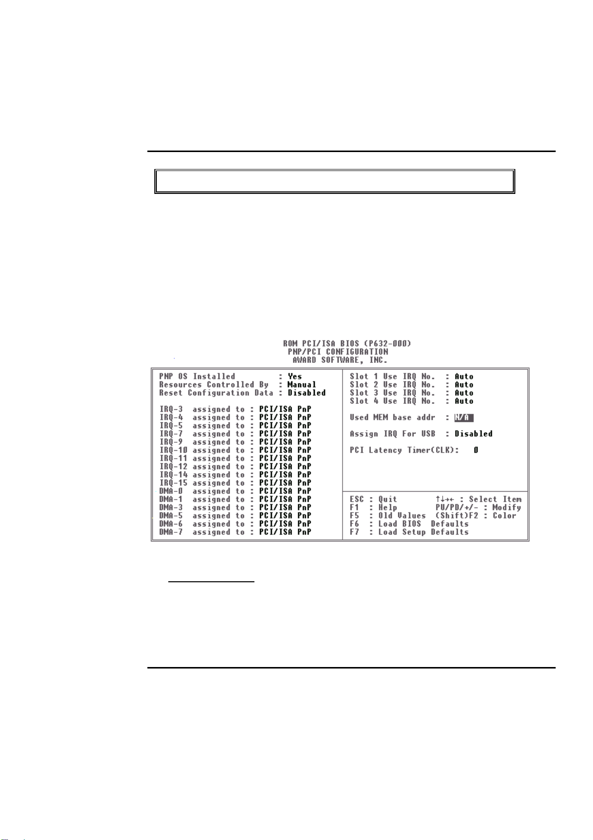
PnP/PCI Configuration
This section describes configuring the PCI bus sy ste m . PCI, orPeripheral
omponentInterconnect, is a system which allows I/O devices to operate at
C
speeds nearing the speed the CPU itself uses when communicating with its own
special components. This section covers some very technical items and it is
strongly rec om mended that only expe rienc ed use rs should m a ke a ny changes to
the default se ttings.
PNP OS Installed
This item allows you to determine install PnP O S or no t.
Choices are Yes and No.
BIOS Setup 4-
27
Page 58

PEAK 632A User Guide
Resource Controlled by
The Award Plug and Play BIOS has the capacity to automatically configure all of the boot
and Plug and Play co mpatible devices. However, this capability means absolutely nothing
unless you are using a Plug and Play operating system such as Windo w s
Choices are
Auto
and Manual (default).
95.
Reset Configuration Data
This item allows y o u to determine reset the conf ig uratio n data or no t.
Choices are
Enabled
and
Disabled
(default).
IRQ/DMA Assigned To
This item allows you to determine the IRQ / DMA assigned to the ISA bus and is not
available to any PCI slot. (Legacy ISA) or PnP for both ISA and PCI.
Choices are
Legacy ISA
PCI/ISA PnP
and
.
PCI IRQ Activated by
This sets the method by which the PCI bus recognizes that an I RQ service is being requested
by a device. Under all circumstances, you should retain the default configuration unless
advised otherwise by y our system manufacturer.
Choices are
Level
(default) and
Edge
.
BIOS Setup 4-
28
Page 59
PEAK 632A User Guide
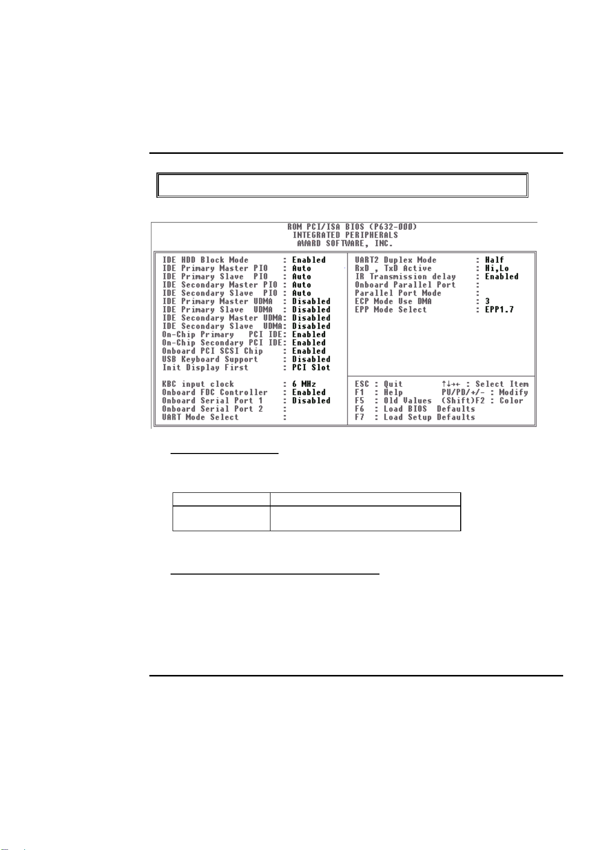
Integrated Peripherals
IDE HDD Block Mode
This allows yo ur hard disk controller to use the fast block modeto transfer data to and from
your hard disk drive (HDD).
Enabled IDE controller uses block mode.
Disabled
(Default)
IDE Primary/Secondary Master /Sl ave PIO
The four IDE PIO (Programmed Input/O utput) f ields let you set a PIO mode (0-4) for each
of the f our I DE devices that the onbo ard IDE interface supports. Mo des 0 through 4 pro vide
successively increased perf ormance. In Auto mode, the sy stem automatically determines the
best mode for each device.
BIOS Setup 4-
IDE controller uses standard mode.
29
Page 60

PEAK 632A User Guide
IDE Primary/Secondary Master/Slave UDM A
Ultra DMA/33 implementation is possible only if your IDE hard drive supports it and the
operating environment includes a DMA driv er (Windows 95 O SR2 or a third- party IDE bus
master driver). If your hard drive and your system software both support Ultra DMA/33,
select Auto to enable BIO S support. The Choice: Auto
(Default)
, Disabled
On-Chip Primary/Secondary PCI IDE
The integrated peripheral controller contains an IDE interface with support for two IDE
channels. Select Enabled
(Default)
to activate each channel separately .
Onboard PCI SCSI Chip
This item allows you to determine whether onboard PCI SCSI chip is enabled
not.
USB Keyboard Support
Select Enabled if your system contains a Universal Serial Bus (USB) controller and you
have a USB keyboard. The Choice: Enabled, Disabled
(Default)
.
(Default)
or
Onboard FDC Controller
Select Enabled if your system has a floppy disk controller (FDC) installed on the system
board and you wish to use it. If you install and-in FDC or the system has no floppy drive,
select Disabled in this field. Cho ices: E nabled
(Default)
, Disabled.
Onboard Serial Port 1/Port 2
This item allow s y o u to determine access onbo ard serial port 1/port 2 co ntroller w ith w hich
I/O address. The Choice: 3F8/IRQ4, 2F8/IRQ3, 3E8/IRQ4, 2F8/IRQ3, Disabled, Auto
(Default)
.
UART 2 Mode
This item allows you to determine which I nf ra Red (I R ) function of onbo ard I /O chip. The
Choice: Standard
BIOS Setup 4-
(Default)
, IrDA1.0, ASK-IR, IrDA1.1
30
Page 61

PEAK 632A User Guide
Duplex Select
This item allows you to select the IR function when your select the UART 2 Mode is
IrDA1.0, ASK-IR, IrDA1.1
Choices are Half, Full.
TxD, RxD Active
This item allows you to determine the active of RxD, TxD.
Choices are i, Hi o, Lo o, Hi i, Lo
Onboard Parallel Por t
Select a logical LPT po rt nam e and matching address f or the physical parallel
(printer) port. The choice: 378H/IRQ7
(Default)
, 278H/IRQ5, 3BCH/IRQ7, Disabled.
Parallel Port Mode
Select an operating mode for the onboard parallel port. Select Compatible or Extended
unless you are certain both your hardware and software support EPP or ECP mode.
The choice: SPP, ECP+EPP1.7, EPP1.7+SPP, EPP1.9+SPP, ECP, ECP+EPP1.9
and Normal.
(Default)
,
ECP Mode Use DMA
Select a DMA channel for the port.
Choices are 3
BIOS Setup 4-
(Default)
, 1.
31
Page 62

PEAK 632A User Guide
Supervisor/User Password Setting
You can set either supervisor or user password, or both of then. The diff erences betw een are:
supervisor password : can enter and chang e the o ptions o f the setup menus.
user password : just can enter but do not have the right to change the
options of the setup menus.
When you select this f unction, the f o llowing message will appear at the center o f the screen to
assist you in creating a passw o rd.
ENTER PASSWORD:
Type the passwo rd, up to eight characters in length, and press <Enter>. The password ty ped now
will clear any previo usly entered passw ord f rom C MOS memory . You w ill be asked to conf irm
the password. T ype the password ag ain and press < Enter> . Y o u may also press <Esc> to abort
the selection and not enter a passwo rd.
To disable a password, just press <Enter> when you are prompted to enter the password. A
message will conf irm the passw ord w ill be disabled. Once the passwo rd is disabled, the sy stem
will boot and you can enter Setup freely.
PASSWORD DISABLED.
When a password has been enabled, you will be pro mpted to enter it every tim e y o u try to enter
Setup. This prevents an unauthorized perso n f rom chang ing any part of yo ur system
configuration.
Additionally, w hen a passw o rd is enabled, you can also require the BIOS to request a passw o rd
every time y o ur system is rebooted. This would prev ent unauthorized use o f y o ur co mputer.
You determine when the password is required within the BI OS Features Setup Menu and its
Security option (see Section 4). If the Security option is set to y stem the password will be
required both at boot and at entry to Setup. I f set to etup prompting only occurs when trying
to enter Setup.
BIOS Setup 4-
32
Page 63

PEAK 632A User Guide
IDE HDD Auto Detection
The Enhance I DE f eatures was included in all Award BIO S. Below is a brief description of
this feature.
1. Setup Changes
<I> Auto-detection
BIOS setup will display all possible m odes that supported by the HD D
including NORMAL, LBA & LARGE.
if HDD does not support LBA modes, no BA ption will be shown.
Users can select a mode which is appro priate fo r them .
ROM/PCI/ISA BOPS (2XXXXXXX)
CMOS SETUP UTILITY
AWARD SOFTWARE, INC.
HARD DISKS TYPE SI ZE CYLS HEAD PRECOMP LANDZ SECTOR MODE
Primary Master :
Select Primary Master Option (N = Skip ) : N
OPTION SIZE CYLS HEADS PRECOMP LANDZONE SECTORS MODE
1(Y) 516 1120 16 65535 1119 59 NORMAL
2 516 524 32 0 1119 63 LBA
3 516 560 32 65535 1119 59 LARGE
<II> Standard CMOS Setup
CYLS Heads Precomp Landzone Sector Mode
Primary Master: User (516MB) 112 0 16 65535 1119 59 Normal
Primary Slave: None (203MB) 684 16 65535 685 38 -----Secondary Master: None 0 0 0 0 0 0
BIOS Setup 4-
33
Page 64

PEAK 632A User Guide
Secondary Slave None 0 0 0 0 0 0
When HDD type is in sertype, the ODEoption will be opened for user to select
their own HDD mode.
(2) HDD Modes
The Award BIO S supports 3 HDD modes : NORMAL, LBA & LARGE
NORMAL mode
Generic access mode in which neither the BIOS nor the IDE controller will make any
transformations during accessing .
The maximum number of cylinders, head & sectors for NORMAL mode are
1024, 16 & 63.
no. Cyclinder (1024)
x no. Head ( 16)
x no. Sector ( 63)
x no. per sector ( 512)
528 Megabytes
If user set his HDD to NORMAL mode, the maximum accessible HDD size will be
528 Megabytes ev en tho ugh its physical size may be g reater than that!
LBA (Logical Block Addressing) mode
A new HDD accessing method to overcome the 528 Megaby te bottleneck . The
number of cylinders, heads & sectors shown in setup may not be the number
physically contained in
the HDD.
During HDD accessing, the IDE controller will transform the logical address
described by sector, head & cylinder number into its own physical address
inside the HDD.
BIOS Setup 4-
34
Page 65

PEAK 632A User Guide
The maximum HDD size supported by LBA mode is 8.4 Gigabytes which is
obtained by
the following fo rmula:
no. Cyclinder ( 1024)
x no. Head ( 255)
x no. Sector ( 63)
x bytes per sector ( 512)
8.4 Gigabytes
LARGE mode
Extended HDD access mode supported by Award So f tw are.
Some IDE HDDs contain more than 1024 cylinder without LBA support (in
some cases, user do not want LBA). The Award BIOS provides another
alternative to support these kinds of HDD!
Example of LARGE mode:
CYLS. HEADS SECTOR MODE
1120 16 59 NORMAL
560 32 59 LARGE
BIOS tricks DOS (or other OS) that the number of cylinders is less than 1024 by
dividing it by 2. At the same time, the number of heads is multiplied by 2. A
reverse transformation process will be made inside INT13h in order to access the
right HDD address the right HDD address!
Maximum HDD size:
no. Cyclinder ( 1024)
x no. Head ( 32)
x no. Sector ( 63)
x bytes per sector ( 512)
1 Gigabytes
BIOS Setup 4-
35
Page 66

PEAK 632A User Guide
BIOS Setup 4-
36
Page 67

PEAK 632A User Guide
(3) Remarks
To support LBA or LARGE mode of HDDs, there must be some softwares
involved. All these softwares are located in the Award HDD Service Routine(INT
13h). It may be
failed to access a HDD with LBA (LARGE) mode selected if you are running
under a Operating System which replaces the w ho le INT 13h.
BIOS Setup 4-
37
Page 68

PEAK 632A User Guide
Power-On Boot
After yo u have m ade all the changes to CM OS v alues and the system cannot
boot with the CMOS v alues selected in Setup, restart the system by turning it
OFF then ON or Pressing the " RESET" button on the system case. You may
also restart by simultaneously press <Ctrl>, <Alt>, and <Delete> k eys.
Upon restart the system, immediately press <Insert> to load BIO S default
CMOS value for boot up.
BIOS Setup 4-
38
Page 69

PEAK 632A User Guide
BIOS Reference - POST Message
During the Power On Self Test (POST), if the BIOS detects an error requiring you to do
something to fix, it will either so und a beep code o r display a m essage.
If a message is display ed, it w ill be accompanied by:
PRESS F1 TO CONTINUE, CTRL-ALT-ESC OR DEL TO ENTER SETUP
POST Beep
Currently there is only one beep code in BIOS. This code indicates that a video error has
occurred and the BIOS cannot initialize the video screen to display any additional
information. This beep code consists of a single long beep followed by two short beeps.
Error Messages
One or more of the following messages may be displayed if the BIOS detects an error
during the POST. T his list includes messages for both the ISA and the EISA BIOS.
CMOS BATTERY HAS FAILED
CMOS battery is no longer functional. It should be replaced.
CMOS CHECKSUM ERROR
Checksum of C MO S is inco rrect. This can indicate that CMO S has beco m e corrupt. This
error may hav e been caused by a weak battery. Check the battery and replace if necessary .
DISK BOOT FAILURE, INSERT SYSTEM DISK AND PRESS ENTER
No boot device was fo und. This could mean that either a boot drive w as not detected or the
drive does not co ntain proper sy stem boot f iles. Insert a system disk into Drive A: andpress
<Enter>. If you assumed the system would boot from the hard drive, make sure the
controller is inserted co rrectly and all cables are properly attached. Also be sure the disk is
formatted as a boot device. Then reboot the system.
DISKETTE DRIVES OR TYPES MISMATCH ERROR - RUN SETUP
BIOS Setup 4-
39
Page 70

PEAK 632A User Guide
Type of diskette drive installed in the system is different from the CMOS definition. Run
Setup to reconfigure the drive type correctly.
BIOS Setup 4-
40
Page 71

PEAK 632A User Guide
DISPLAY SWITCH IS SET INCORRECTLY
Display switch on the motherboard can be set to either monochrome or color. This
indicates the switch is set to a different setting than indicated in S etup. Determine which
setting is correct, and then either turn o ff the sy stem and change the jum per, or enter Setup
and change the VIDEO selection.
DISPLAY TYPE HAS CHANGED SINCE LAST BOOT
Since last powering off the system, the display adapter has been changed. You must
configure the sy stem f o r the new display type.
EISA Configuration Checksum Error
PLEASE RUN EISA CONFIGURATION UTILITY
The EISA non-v olatile RA M checksum is incorrect or cannot correctly read the EI S A slot.
This can indicate either the EISA non-volatile memory has become corrupt or the slot has
been configured incorrectly . Al so be sure the card is installed f irm ly in the slot.
EISA Configuration Is Not Complete
PLEASE RUN EISA CONFIGURATION UTILITY
The slot configuration info rm atio n stored in the EISA non-volatile m emo ry is incomplete.
Note: When either of these errors appear, the system will boot in ISA mode, which
allows you to run the EISA Configuration U tility.
ERROR ENCOUNTERED INITIALIZING HARD DRIVE
Hard drive cannot be initialized. Be sure the adapter is installed correctly and all cables are
correctly and firmly attached. Also be sure the correct hard drive ty peis selected in Setup.
ERROR INITIALIZING HARD DISK CONTROLLER
Cannot initialize controller. Make sure the cord is correctly and f irmly installed in the bus.
Be sure the correct hard drive type is selected in Setup. Also check to see if any jumper
needs to be set correctly on the hard drive.
BIOS Setup 4-
41
Page 72

PEAK 632A User Guide
FLOPPY DISK CNTRLR ERROR OR NO CNTRLR PRESENT
Cannot find or initialize the floppy drive controller. make sure the controller is installed
correctly and firmly. If there are no floppy drives installed, be sure the Diskette Drive
selection in Setup is set to NONE.
Invalid EISA Configuration
PLEASE RUN EISA CONFIGURATION UTILITY
The non-volatile memory containing EISA configuration information was programmed
incorrectly or has beco m e corrupt. Re- run E I S A co nf ig uration utility to correctly pro gram
the memory.
NOTE: When this error appears, the system will boot in ISA mode, which allows you
to run the EISA Configuration Utility.
KEYBOARD ERROR OR NO KEYBOARD PRESENT
Cannot initialize the keyboard. Make sure the keyboard is attached correctly and no keys
are being pressed during the boot.
If y ou are purposely co nfigurating the sy stem without a k eyboard, set the error halt co ndition
in Setup to HALT ON ALL, BUT KEYBOARD. This will cause the BIOS to ignore the
missing key board and co ntinue the bo ot.
MEMORY ADDRESS ERROR AT ...
Indicates a memory address error at a specific location. You can use this location along
with the memory map for yo ur system to find and replace the bad memory chips.
MEMORY PARITY ERROR AT ...
Indicates a memo ry parity error at a specif ic location. Yo u can use this location along w ith
the memory m ap f or your system to f ind and replace the bad memory chips.
MEMORY SIZE HAS CHANGED SINCE LAST BOOT
Memory has been added or remo ved since the last boot. I n EISA mode use Configuration
Utility to reconfigure the memory configuration. In ISA mode enter Setup and enter the
new memory size in the memory fields.
BIOS Setup 4-
42
Page 73

PEAK 632A User Guide
MEMORY VERIFY ERROR AT ...
Indicates an error verify ing a value already written to memory . Use the location along with
your sy stem 's memory map to locate the bad chip.
OFFENDING ADDRESS NOT FOUND
This message is used in conjunction with the I/O CHANNEL CHECK and RAM PARITY
ERROR messages w hen the segm ent that has caused the problem cannot b e isolated.
OFFENDING SEGMENT:
This message is used in conjunction with the I/O CHANNEL CHECK and RAM PARITY
ERROR messages w hen the seg ment that has caused the problem has been isolated.
PRESS A KEY TO REBOOT
This will be displayed at the bottom screen when an error occurs that requires you to
reboot. Press any key and the system will reboot.
PRESS F1 TO DISABLE NMI, F2 TO REBOOT
When BIOS detects a No n-mask able I nterrupt co ndition during boo t, this w ill allow y o u to
disable the NMI and continue to boot, o r you can reboot the sy stem with the NMI enabled.
RAM PARITY ERROR - CHECKING FOR SEGMENT ...
Indicates a parity error in Random Access Mem ory.
SHOULD BE EMPTY BUT EISA BOARD FOUND
PLEASE RUN EISA CONFIGURATION UTILITY
A valid board I D was found in a slot that was configurated as having no board ID.
NOTE; When this error appears, the system will boot in ISA mode, which allows you
to run the EISA Configuration Utility.
BIOS Setup 4-
43
Page 74

PEAK 632A User Guide
SHOULD HAVE EISA BOARD BUT NOT FOUND
PLEASE RUN EISA CONFIGURATION UTILITY
The board installed is not responding to the ID request, o r no board ID has been found in the
indicated slot.
NOTE: When this error appears, the system will boot in I SA mo de, which allo ws y ou
to run the EISA Configuration Utility.
SLOT NOT EMPTY
Indicates that a slot designated as empty by the EISA Configuration Utility actually
contains a board.
NOTE: When this error appears, the system will boot in ISA mode, which allows you
to run the EISA Configuration Utility.
SYSTEM HALTED, (CTRL-ALT-DEL) TO REBOOT ...
Indicates the present boot attempt has been aborted and the system must be rebooted. Press
and hold down the CTRL and ALT keys and press DEL.
WRONG BOARD IN SLOT
PLEASE RUN EISA CONFIGURATION UTILITY
The board ID does not match the I D stored in the EISA non -volatile memory.
NOTE: When this error appears, the sy stem will boot in I SAmode,
which allows you to run the EISA Configuration tility.
BIOS Setup 4-
44
Page 75
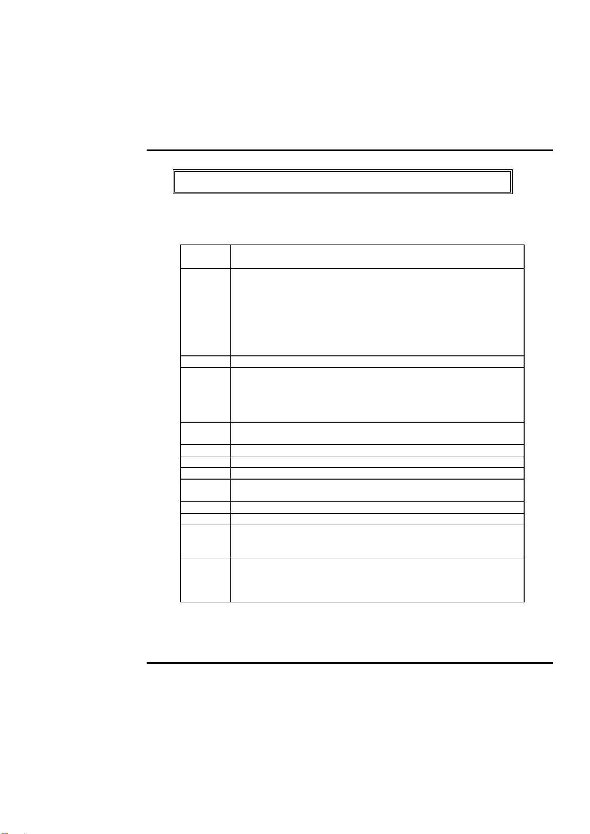
PEAK 632A User Guide
BIOS Reference - POS T Codes
Note:
EISA POST codes are typically output to port address 300h.
ISA POST codes are output to port address 80h.
POST
(hex)
C0 1. Turn of f OEM spec ifi c cache, shadow...
C1 Auto -d ete ct i on of onboa rd DRA M & C ac he
C3 1. Test system BIOS checksum
C5 Copy the BIOS from ROM into E0000-FFFFF shadow R AM so
01-02 Reserved
03 Initia lize EISA register s (EISA BIOS only)
04 Reserved
05 1. Keyboard Controller Sel f-Test
06 Reserved
07 Verifi es CMOS basic R /W functional ity
BE Program defaults values into chipset according to the
09 1. Program the confi guration register of Cyrix CPU acc ording
Description
2. Initialize all the standard devices with default values
standard devices
includes:
-DMA controller (8237)
-Programmable Inter rupt Controller (8259)
-Programmable Inter val Timer (8254)
-RTC chip
2. Test the first 256K DR AM
3. Expand the compressed codes into temporary DRAM a rea
including the
compressed System BIOS & Option ROMs
that POST will go faster
2. Enable Keyboard Interface
MODBINable Chipset
Default Tabl e
to the
MODBINable Cyrix Regi ster Tabl e
2. OEM specific cache initial ization (if needed)
BIOS Setup 4-
45
Page 76

PEAK 632A User Guide
0A 1. Initialize the first 32 interrupt vectors with corresponding
Interrupt handlers
Initialize INT no f r om 33-120 with D umm y(Supri ous)
Interrupt Handler
2. Issue CPUID instruction to identif y CPU type
3. Early Power Management initialization ( OEM specif ic)
BIOS Setup 4-
46
Page 77
PEAK 632A User Guide
! This POST code is for boot block
POST
(hex)
C0 1. Turn of f OEM s pecifi c cache, shadow...
C1 Auto -d et ect i on of onboa rd DR AM & Ca che
C3 Checking checksum of compressed code
C5 Copy the BIOS from ROM into E0000-FFFFF shadow RAM
01 Clear base mem ory 0~640K
0C Init ial interrupt v ector 00-1F H
0D Initial ISA VGA
41H Enable FDD and detect media type
FFH Boot from FD D
Description
2. Initialize all the standard devices with default values
standard devices
includes:
-DMA controller (8237)
-Programmable Inter rupt Controller (8259)
-Programmable Inter val Timer (8254)
-RTC chip
so that POST will go f aster
BIOS Setup 4-
47
Page 78

PEAK 632A User Guide
! This page is for Non -Compressed Version only
01-0
2
C0 Tur n off OEM speci fic cache, shadow...
03 1. Initiali ze EISA register s (EISA BIOS only)
04 Reserved
05 1. Keyboard Controll er Self-T est
06 Reserved
07 Verif ies CMOS basic R/W functi onality
BE Program defaults values into chipset according to the
C1 Aut o -d ete ct i on of onboar d D RAM & C ach e
C5 Copy the BIOS from R OM into E0000-FFFFF shadow RAM
08 Test the f irs t 256K DR AM
09 1. Program the configuration register of Cyrix CPU according
0A 1. Initialize the fi rst 32 interrupt vectors with corresponding
Reserved
2. Initialize all the standard devices with default values
Standard devices incl udes:
-DMA controller (8237)
-Programmable Inter rupt Controller (8259)
-Programmable Inter val Timer (8254)
-RTC chip
2. Enable Keyboard Interface
MODBINable Chipset
Default Table
so that POST will go f aster
to the
MODBINable Cyrix Regi ster T abl e
2. OEM specific cache i nitialization (if needed)
Interrupt
handlers Initialize INT no from 33-120 with
Dummy(Suprious)
Interrupt Handler
2. Issue CPUID instruction to identif y CPU type
3. Early Power Management initialization ( OEM specif ic)
BIOS Setup 4-
48
Page 79
PEAK 632A User Guide
! The following POST Codes are for all of Compress Version &
Non-Compress Version
POST
(hex)
0B 1. Verify the RTC time is valid or not
0C
0D 1. Program some of the Chipset value according to Setup.
0E 1. Initialize the APIC (Multi -Processor BIOS onl y)
0F DMA channel 0 test
10 DM A channel 1 tes t
11 DM A page registers test
12-13 Reserved
14 T est 8254 Tim er 0 Counter 2.
15 T est 8259 interrupt mask bits for channel 1
16 T est 8259 interrupt mask bits for channel 2
17 Reserved
19 T est 8259 functionalit y
1A-1D Reserved
Description
2. Detect bad battery
3. Read CMOS data into BIOS stac k area
4. PnP initializations including ( PnP BIOS only)
-Assign CSN to PnP ISA card
-Create resource map fr om ESCD
5. Assign IO & Memory for PCI devi ces ( PCI BIOS o nly)
Initialization of the BIOS Data Ar ea (40 : 00−40:FF)
(Early Setup
Value Program)
2. Measure CPU speed for display & decide the system
clock speed
3. Video initialization including Monochrome, CGA,
EGA/VGA. If no
display device found, the speaker will beep which
consists of one single
long beep followed by two short beeps.
2. Test video RAM (If Monochrom e di splay devi ce found)
3. Show messages including:
-Award Logo, Copyright string, BIOS Date code & Part
No.
-OEM specific sign on messages
-Energy Star Logo (Green BIOS ONLY)
-CPU brand, type & speed
-Test system BIOS checksum(Non-Compress
Version only)
BIOS Setup 4-
49
Page 80
PEAK 632A User Guide
1E If EISA NVM checksum is good, execute EISA initial ization
1F-29 Reserved
30 Detect Base Memory & Extended Mem ory Size
31 1. T est Base Mem ory fr om 256K to 640K
32 1. Display the Award Plug & Play BIOS Extension message
33-3B Reserved
3C Set flag to allow users to enter CMOS Setup Utility
3D 1. Initi alize Keyboard
(EISA BIOS only)
2. Test Extended M emor y from 1M to the top of mem ory
(PnP BIOS
only)
2. Program all onboard super I/O chips (if any) including
COM ports, LPT
ports, FDD port... according to setup value
2. Install PS2 mouse
BIOS Setup 4-
50
Page 81

PEAK 632A User Guide
POST(hex) Description
3E T r y to turn on Level 2 cache
3E T r y to tur n on Level 2 c ache
BF 1. Program the rest of the Chipset value according to
41 Initialize f loppy disk drive contr oller
42 Initialize Hard drive controller
43 If it is a PnP BIOS, initialize serial & parallel ports
44 Reserved
45 Initialize math coprocessor.
46-4D Reserved
4E If there is any error detected (such as video, kb...), show all
4F 1. If password is needed, ask for password
50 Write all CMOS values currently in the BIOS stack area
51 Reserved
52 1. Initialize all ISA ROMs
Note: Some chipset may need to turn on the L2 cache in
this stage. But usually, the cache is turn on later i n POST
61h
Note: Some chipset may need to turn on the L2 cache in
this stage. But usually, the cache is turn on l ater in POST
61h
Setup. (Later Setup
Value Program)
2. If auto-configur ati on i s enabl ed, pr ogr am m ed the chipset
with pre-
defined values i n the M ODBIN able Auto-Tab le
the error m essages on the screen & wait f or user to press
<F1> key
2. Clear the Energy Star Logo (Gr een BIOS only)
back into the CMOS
2. Later PCI ini tializations (PCI BIOS only)
-assign IRQ to PCI device s
-initialize all PCI ROMs
3. PnP Initializations (PnP BIOS only)
-assign IO, Memory, IRQ & DMA to PnP ISA dev ic es
-initialize all PnP ISA ROMs
4. Program shadows RAM according to Setup s ettings
5. Program parity according to Setup setting
6. Power Management Init iali zation
-Enable/Disable global PM
-APM interface initialization
BIOS Setup 4-
51
Page 82
PEAK 632A User Guide
53 1. If it is NOT a PnP BIOS, initialize serial & parallel ports
2. Initialize time v alue in BIOS data area by translate the
RTC time value
into a timer tick value
60 Setup Virus Protection (Boot Sector Protection)
functionality according to Setup settin
BIOS Default Drive Table
This is a current list of the drive type table contained in Setup.
Type Size
(MB)
1 10 306 4 17 128 305 T EAC
2 20 615 4 17 300 615 Seagate
3 30 615 6 17 300 615
4 62 940 8 17 512 940
5 46 940 6 17 512 940
6 20 615 4 17 None 615 Seagate
7 30 462 8 17 256 511
8 30 733 5 17 None 733 Tandon TM
9 112 900 15 17 None 901
10 20 820 3 17 None 820
11 35 855 5 17 None 855
12 49 855 7 17 None 855
13 20 306 8 17 128 319 Di sctron
14 42 733 7 17 None 733
15 Reserved
Cylinders Heads SectorsWrite
Precomp
Land
Zone
Example
Model
SD510,
MMI 112,
5412
ST225,
ST4026
ST125,
Tandon
TM262
703
526, MMI
M125
BIOS Setup 4-
52
Page 83
PEAK 632A User Guide
16 20 612 4 17 0 663 Microscien
17 40 977 5 17 300 977
18 56 977 7 17 None 977
19 59 1024 7 17 512 1023
20 30 733 5 17 300 732
21 42 733 7 17 300 732
22 30 306 5 17 300 733 Seagate
23 10 977 4 17 0 336
ce HH725,
Syquest
3250, 3425
ST4038
BIOS Setup 4-
53
Page 84
PEAK 632A User Guide
24 40 1024 5 17 None 976 Seagate
25 76 1224 9 17 None 1023 Seagate
26 71 1224 7 17 None 1223 Maxtor 2085
27 111 1224 11 17 None 1223 Maxtor 2140,
28 152 1024 15 17 None 1223 Maxtor 2190,
29 68 1024 8 17 None 1023 Maxtor 1085,
30 93 918 11 17 None 1023 Maxtor 1105
31 83 925 11 17 None 1023 Maxtor 1170
32 69 1024 9 17 None 926 CDC 9415
33 85 1024 10 17 None 1023
34 102 1024 12 17 None 1023
35 110 1024 13 17 None 1023
36 119 1024 14 17 None 1023
37 17 1024 2 17 None 1023
38 136 1024 16 17 None 1023
39 114 918 15 17 Non e 1023 Maxtor 1140,
40 40 820 6 17 None 820 Seagate
41 42 1024 5 17 None 1023 Seagate 4053
42 65 1024 5 26 None 1023 Miniscribe
43 40 809 6 17 None 852 Miniscribe
44 61 809 6 26 None 852 Miniscribe
45 100 776 8 33 None 775 Conner
46 203 684 16 38 None 685 Conner
User
ST4051
ST4096
Priam S14
Priam S19
Micropolis
1325
1120, 4780
4380
ST251
Miniscribe
3053/6053
3053/6053
RLL
3650
3675 RLL
CP3104
CP3204
BIOS Setup 4-
54
Page 85

PEAK 632A User Guide
BIOS Setup 4-
55
Page 86
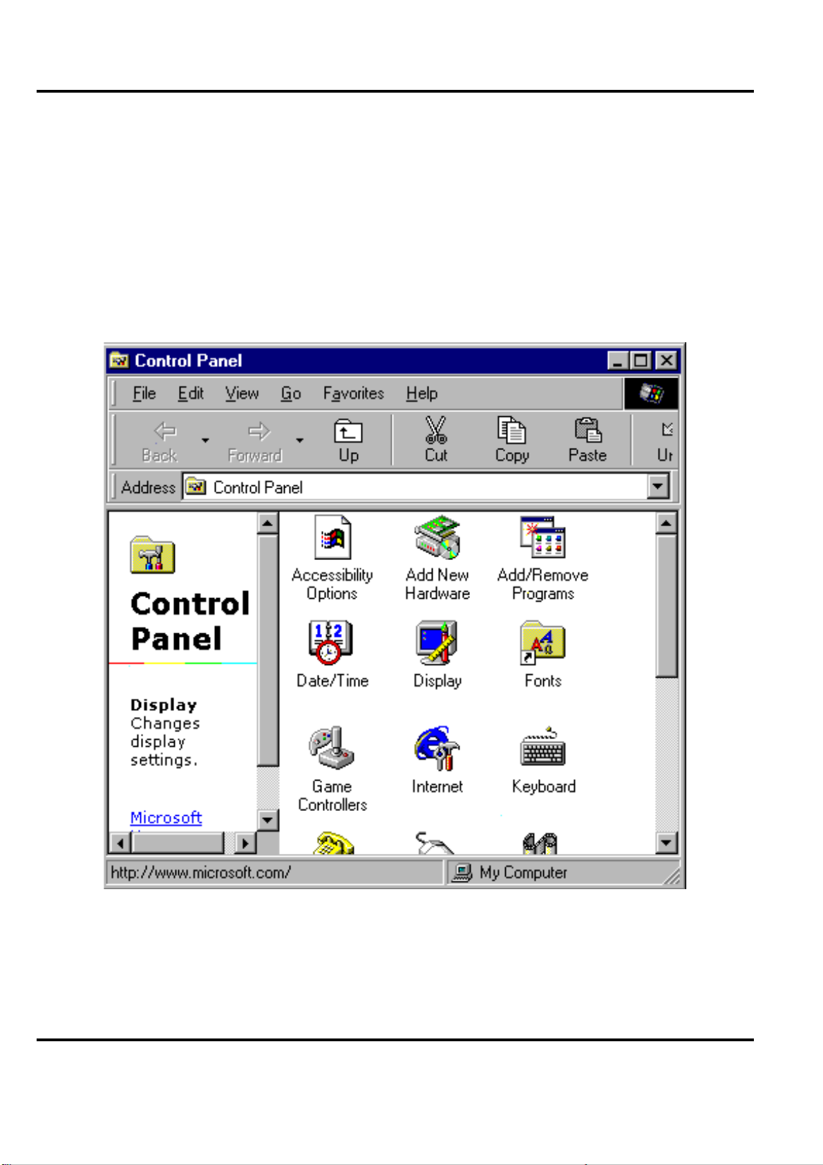
Peak 632A User's Guide
Chapter 5
VGA Driver Installation Procedures
5.1 Windows 95/98 Drivers Setup Procedure
1. In the″Control Panel″screen, select the″Display” icon and click″Display Type″.
Figure 5-1: Opening the Wi ndows Control Pane l
VGA Driver Installation Procedures
5-1
Page 87
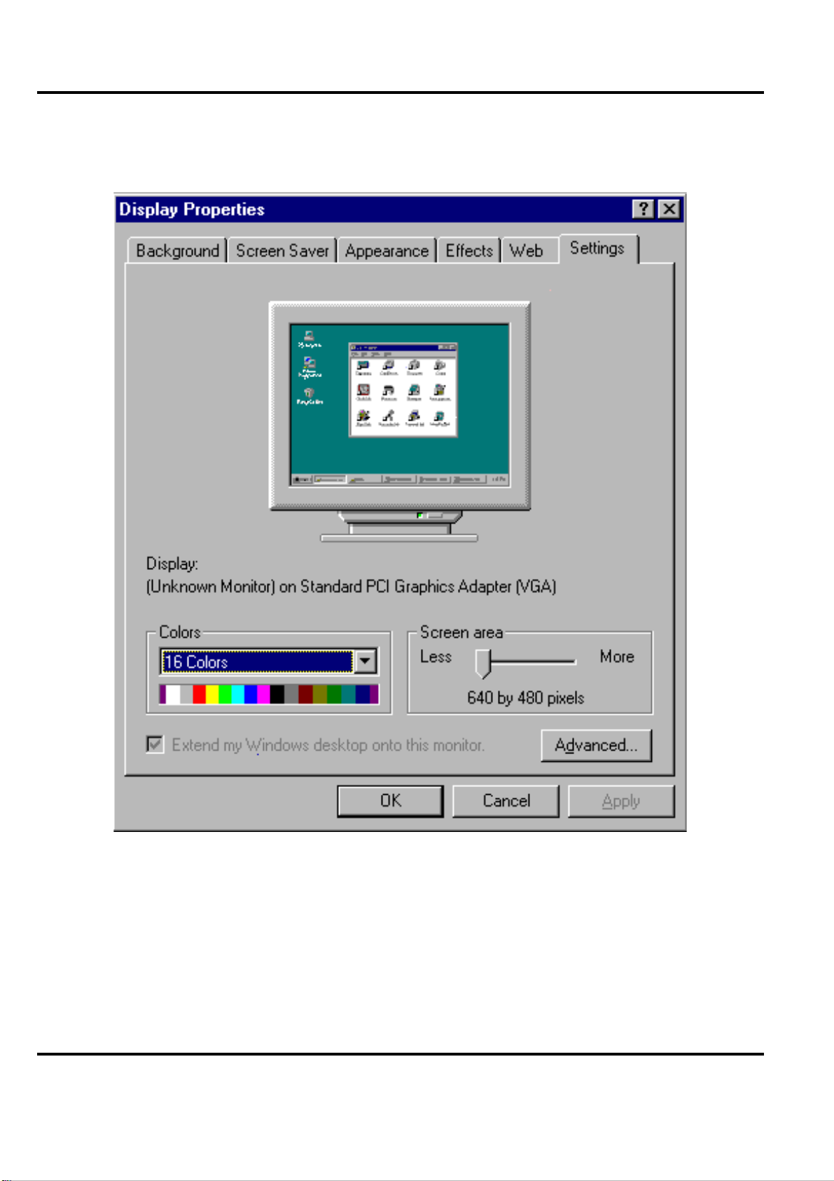
Peak 632A User's Guide
2. When installing Windows 95/ 98, choose the″Settings″icon.
Figure 5-2: Open″Display Type″from the Windows Control Panel
VGA Driver Installation Procedures
5-2
Page 88
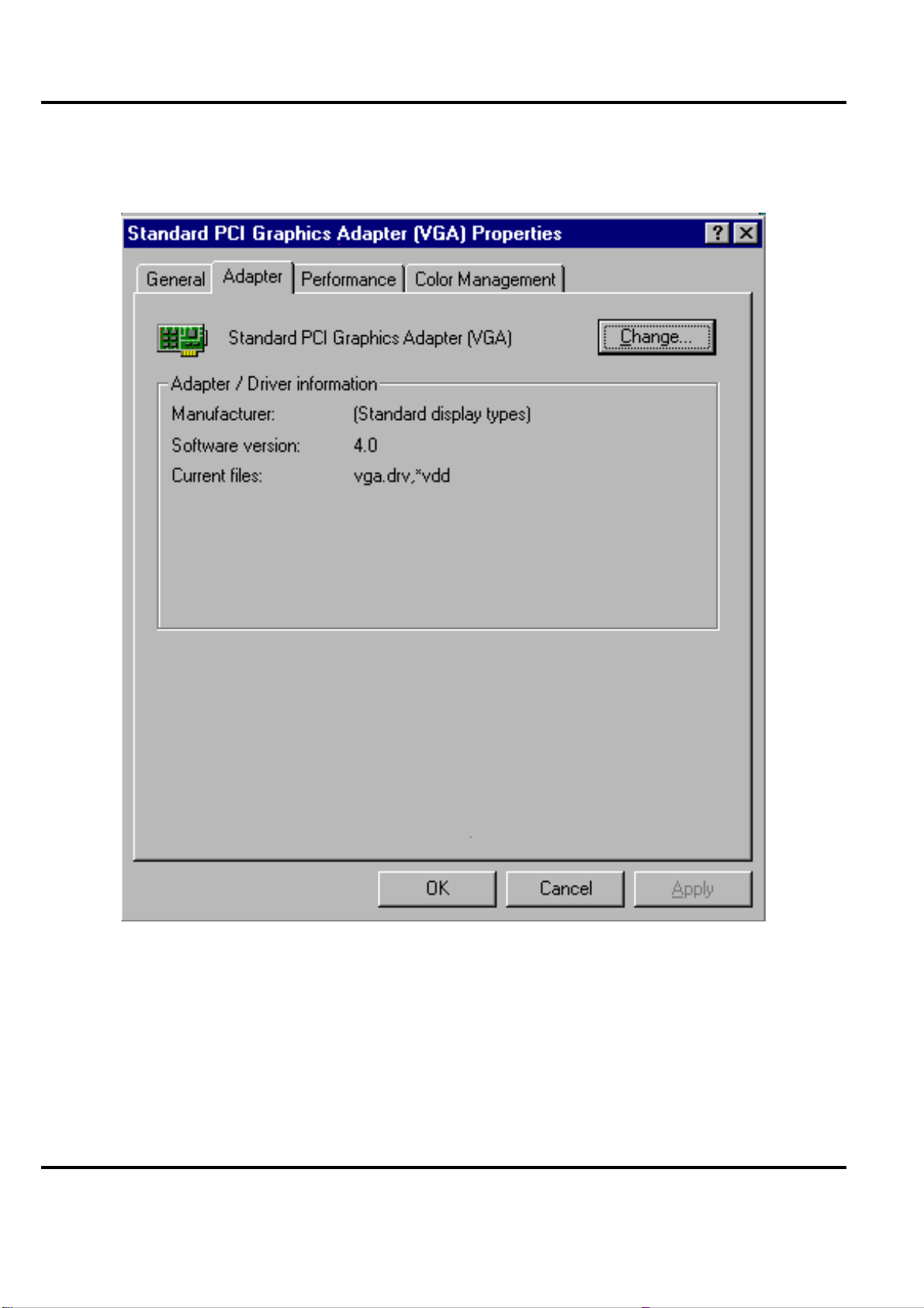
Peak 632A User's Guide
3. Click″Change″.
Figure 5-3: Clicking the″Change″button within″Display Type″.
VGA Driver Installation Procedures
5-3
Page 89
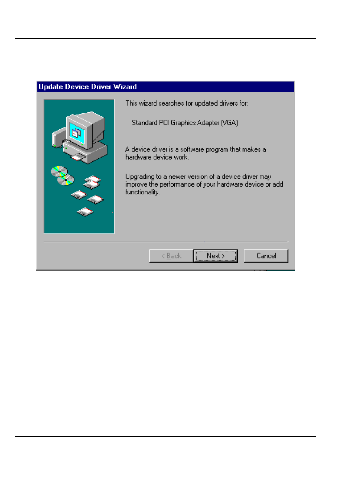
Peak 632A User's Guide
4. Click″Next″.
Figure 5-4: Clicking the″Next″button
VGA Driver Installation Procedures
5-4
Page 90
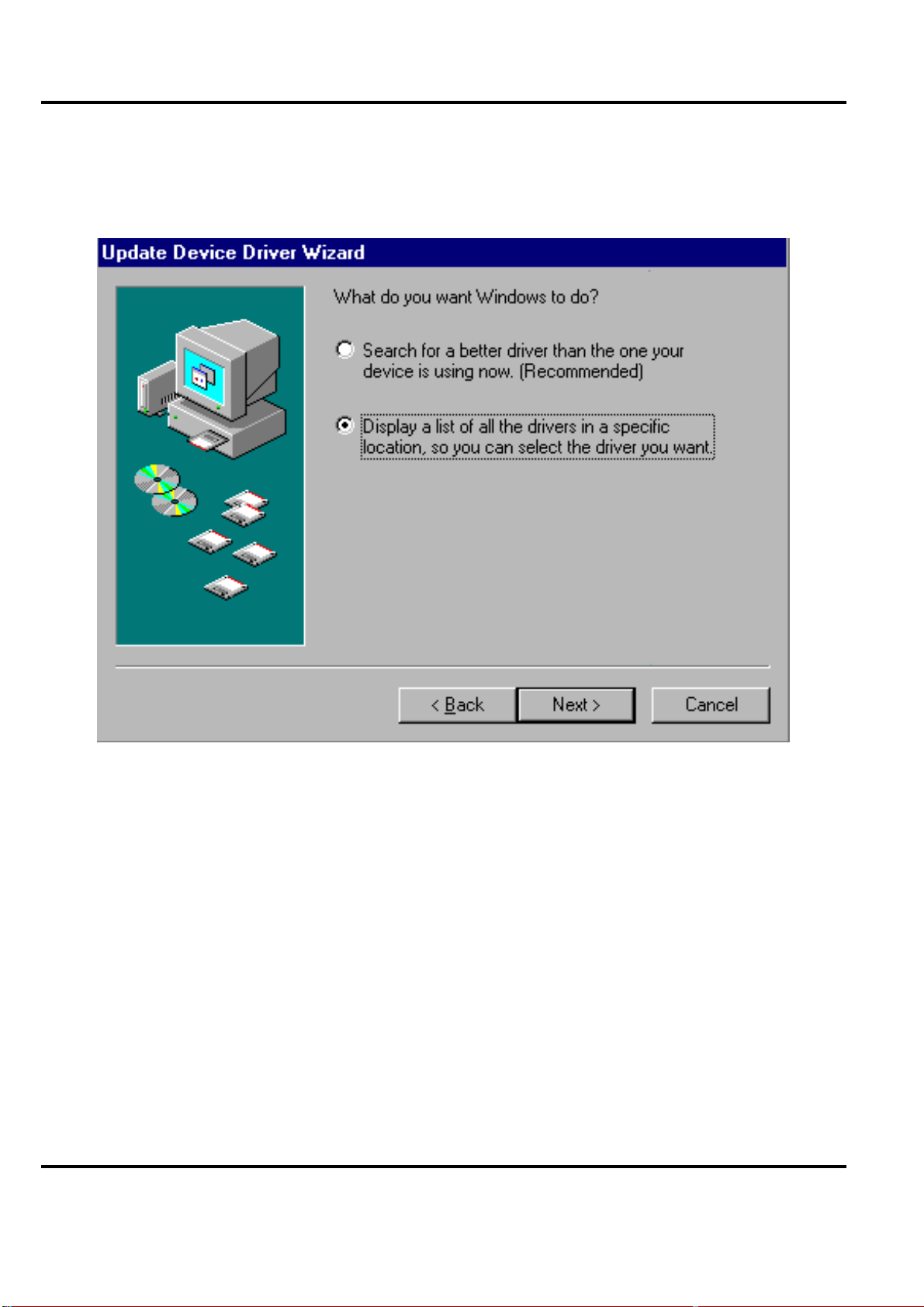
Peak 632A User's Guide
5. Select″Display a list of all the drivers i n a specific location, so you can select the driver
you want.
″
Figure 5-5: C hoosing Di spl ay ada pte rs from t he Ha rdware type s li st
VGA Driver Installation Procedures
5-5
Page 91
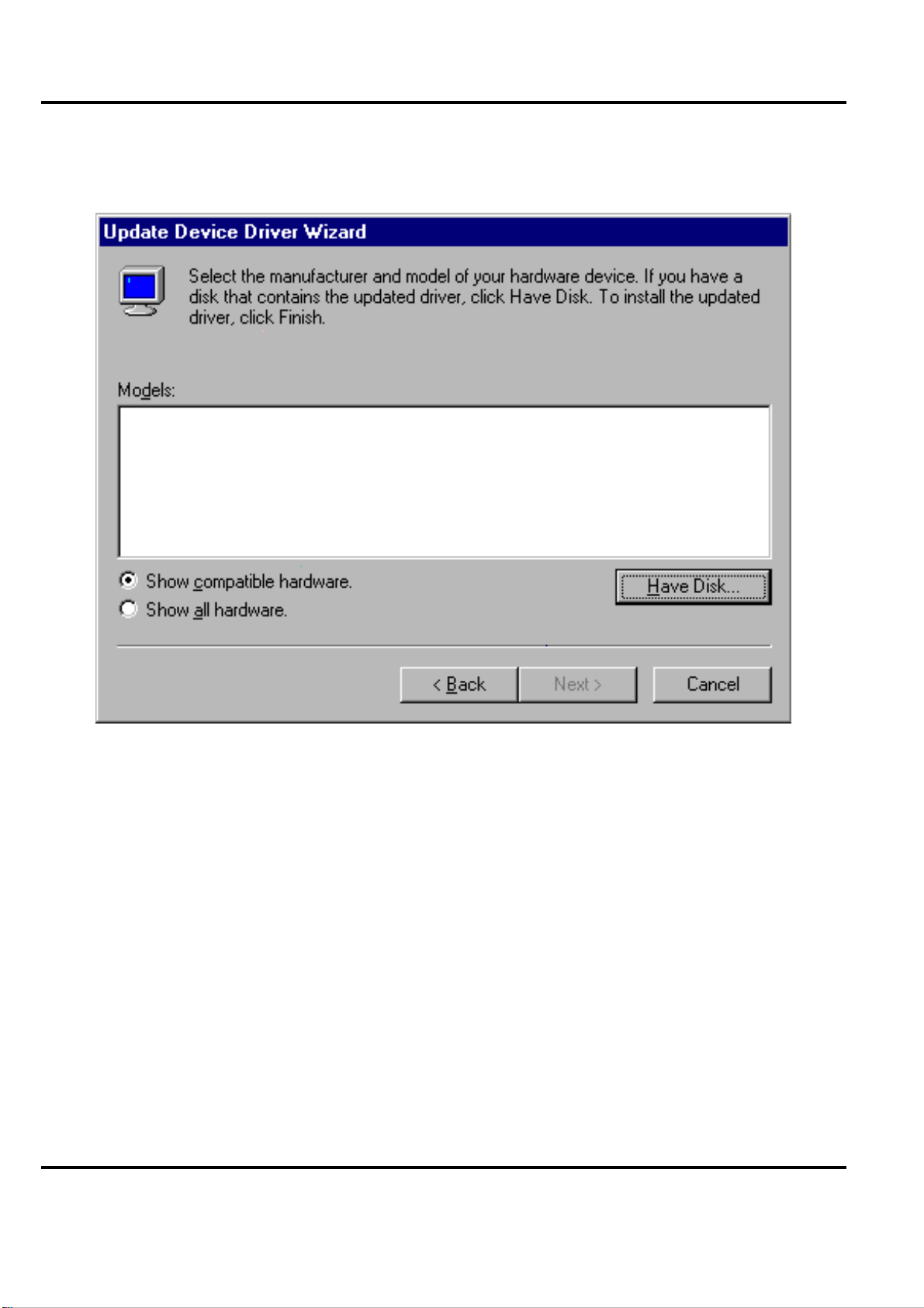
Peak 632A User's Guide
6. Click″Have Disk″.
Figure 5-6: Selecting″Have Disk″button.
VGA Driver Installation Procedures
5-6
Page 92
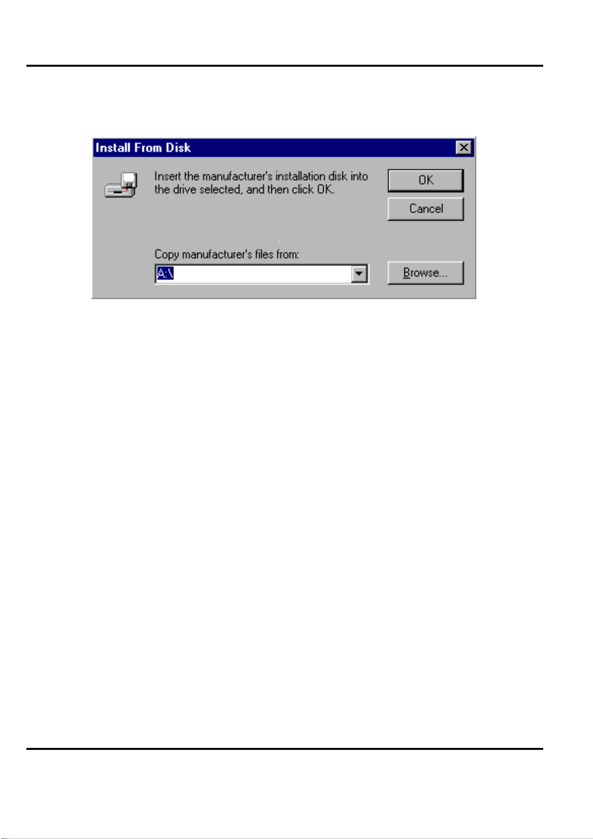
Peak 632A User's Guide
7. Click on″Browse…″to look for the driver program.
Figure 5-7: Cli cking on the″Browse″button
VGA Driver Installation Procedures
5-7
Page 93
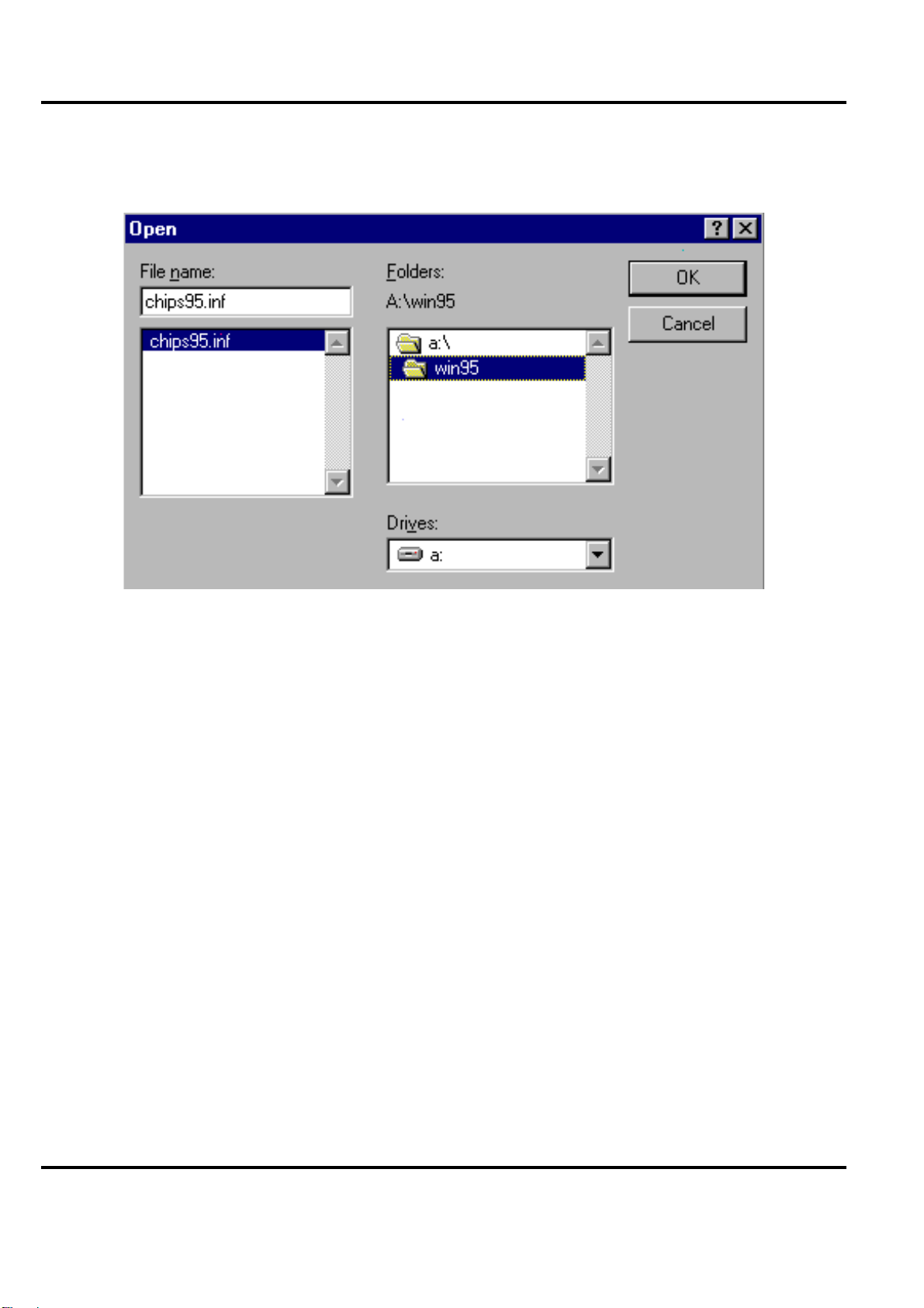
Peak 632A User's Guide
8. Select″chips95.inf″in the penwindow, and cli ck on K
Figure 5-8: Selecting″chips98.inf
″
VGA Driver Installation Procedures
5-8
Page 94
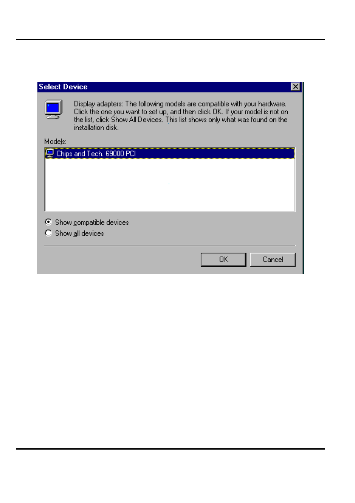
Peak 632A User's Guide
9. Select″Chips and Tech. 69000 PCI″and click on″OK″.
Figure 5-9: Selecting Chips and Tech. 69000 PCI
VGA Driver Installation Procedures
5-9
Page 95
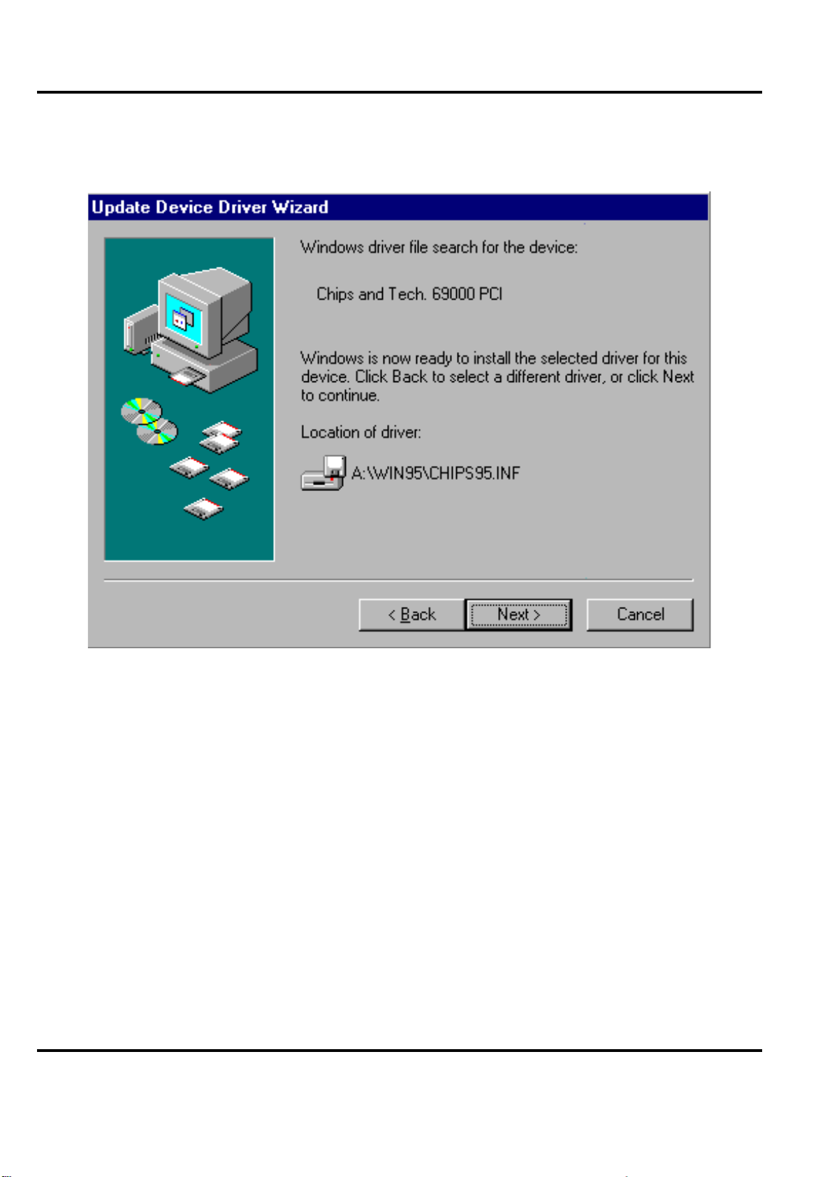
Peak 632A User's Guide
10. Click on″Next″to start copying the drive r.
Figure 5-10: Cli cking on the Next button
VGA Driver Installation Procedures
5-10
Page 96
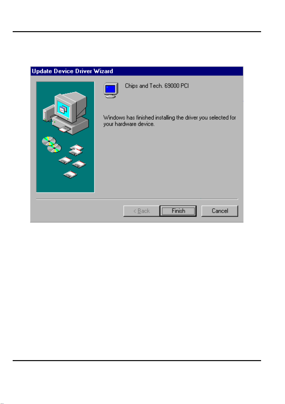
Peak 632A User's Guide
11. Click on″Finish″to complete the setup procedure.
Figure 5-11: Cli cking on″Finish
VGA Driver Installation Procedures
″
5-11
Page 97
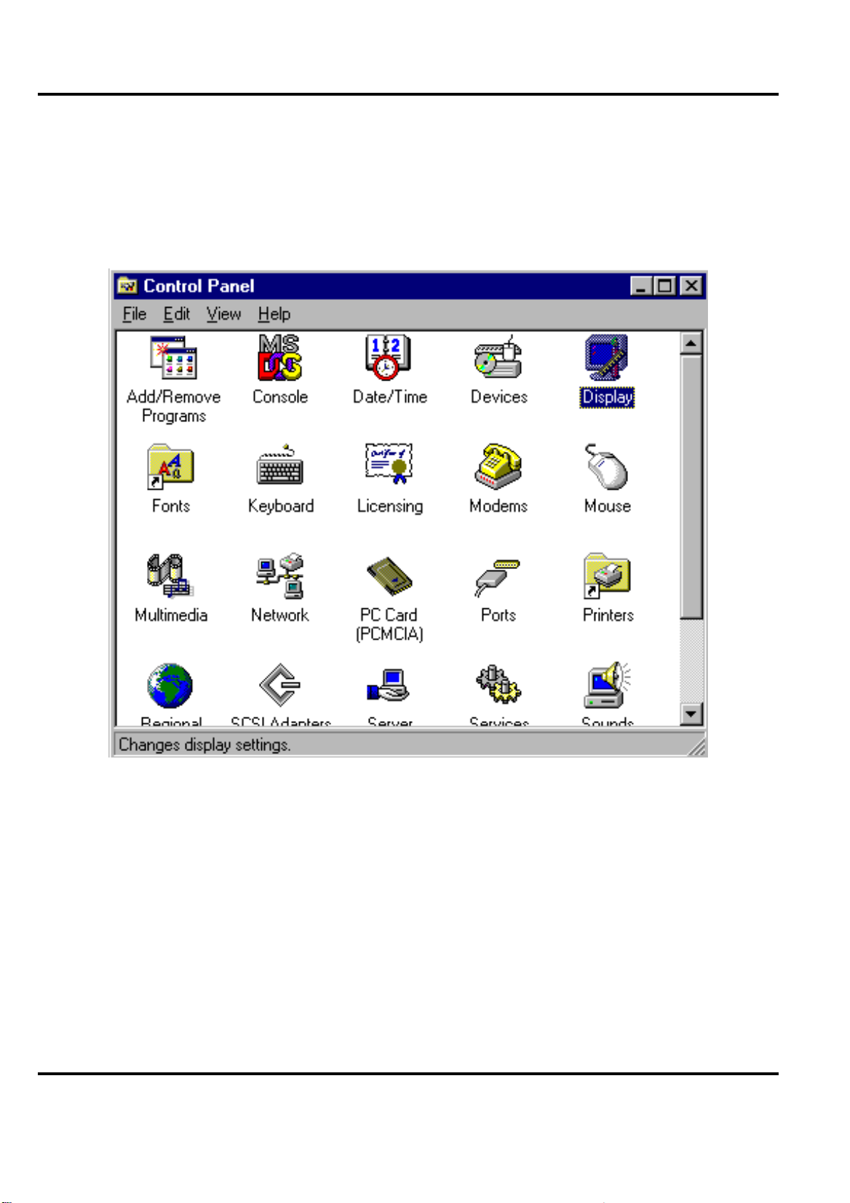
Peak 632A User's Guide
5.2 Windows NT Drivers Setup Procedure
1. In the″Control Panel″screen, select the″Display″icon.
Figure 5-12: Clicking on Display Type in the Settings tab
VGA Driver Installation Procedures
5-12
Page 98
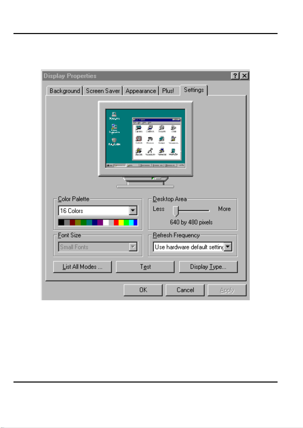
Peak 632A User's Guide
2. In the isplay Propertieswindow, select the ettingstab and click on″Display Type″.
Figure 5-13: Choosing Setting tab and clicking Display Type button
VGA Driver Installation Procedures
5-13
Page 99
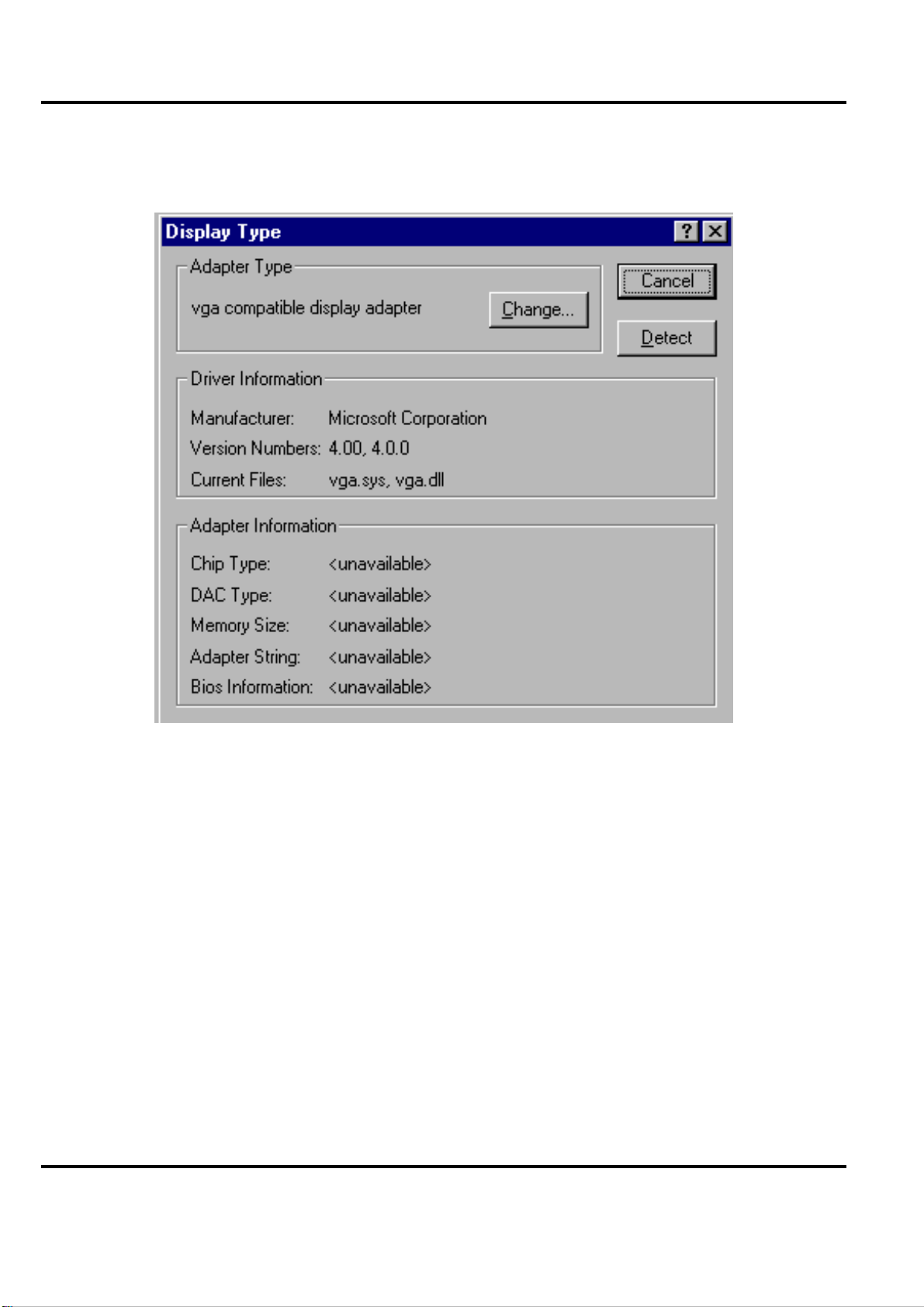
Peak 632A User's Guide
3. Click on″Change…″in the Display Type window.
Figure 5-14: Clic king on the Change button
VGA Driver Installation Procedures
5-14
Page 100
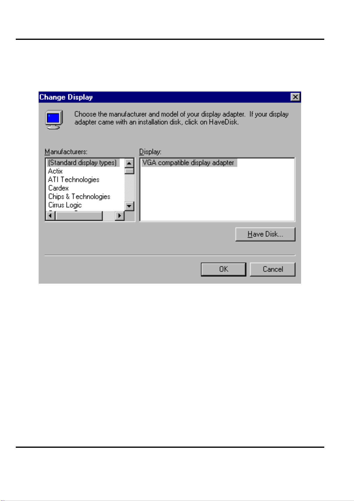
Peak 632A User's Guide
4. Click on″Have Disk…″in the Change Display wi ndow.
Figure 5-15: Clic king on the Have Disk button
VGA Driver Installation Procedures
5-15
 Loading...