

Page 1

Peak 555A
Single Board Computer
User′s Guide
All brand names are registered trademarks of their owners.
Page 2

@Copyright 1999
All Rights Reserved
Manual edition 1, April 1999
The information in this document is subject to change without prior notice in
order to improve reliability, design and function and does not represent
commitment on the part of the manufacturer.
In no event will the manufacturer be liable for direct, indirect, special,
incidental, or consequential damages arising out of the use or the possibility of
such damages.
This document contains proprietary information protected by copyright. All
rights are reserved. No part of this manual may be reproduced by any
mechanical, electronic, or other means in any form without prior written
permission of the manufacturer.
Trademarks
Peak 555A is registered trademarks of Nexcom International Co., Ltd., IBM
PC is a registered trademark of International Business Machines Corporation.
Intel and Pentium are registered trademarks of Intel Corporation. Award is
registered trademarks of Award Software, Inc. Other product names
mentioned herein are used for identification purposes only and may be
trademarks and/or registered trademarks of their respective companies.
Page 3

1.1
2.1
2.2
3.1 System
3.2 Cache
4.1 Entering
4.2 The Main
4.3 Standard CMOS
4.4 BIOS Features
4.5 Chipset Features
4.6 Power Management
4.7 PCI & On board I/O
28
29
4.11 IDE Auto
Table of Contents
How to Use This Guide
Chapter 1. Introduction
Chapter 2. Switches and Connectors
Chapter 3. Capability Expanding
Chapter 4. Award BIOS Setup
Specifications.............................................................................…
1 - 3
1.2 What you have ………………………………………………….. 1-6
Switches.......................................................................................
.2- 1
Connectors...................................................................................
.2- 5
Memory........................................................................… 3-1
Memory .........................................................................… 3-3
3.3 Change CPU……….…………………………………………….3-3
Setup...............................................................................4-1
Menu ............................................................................. 4-4
Setup ..............................................…................. 4-7
Setup. ...............................................................…4-11
Setup..................................................................4-16
Setup.............................................................4-21
setup.............................................................4-26
4.8 System Environment …………………………………………… 4-
4.9 Integrated Peripherals……………………………………………4-
4.10 Supervisor/User Password Setting ……………………………. 4-32
Page 4

Detection .................................................................... 4-33
4.12 Power On
POST
38
Appendix 1 Watch Dog Timer
Appendix 2 Memory Mapping
Boot......................................................................….4-37
4.13 BIOS Reference-
Message............................................…4-
4.14 BIOS Reference-POST Code ……………….........................…4-43
4.15 BIOS Default Drive Table ……………………………………. 4- 49
Page 5

How to use this guide
This manual is written to help you use Peak 555A. The manual describes how
to arrange various settings on the Pentium CPU board to meet your
requirements. It‘s briefed as follows:
Chapter 1, “Introduction” gives an overview of the product‘s specifications.
It also tells you what are included in the product package.
Chapter 2, “Jumpers and Connectors” describes the definitions and positions
of Jumpers and Connectors that you may easily configure and set up per your
requirement.
Chapter 3, “Capability Expanding” describes how to change or expand the
CPU Board by changing the system memory, cache memory, and CPU to get
more power out from the CPU board.
Chapter 4, “Award BIOS Setup” describes how to use the advanced
PCI/Green BIOS to control almost every feature of the Peak 555A, including
the watchdog timer.
The Appendix describes how to set up the Watch Dog Timer (WDT) and
gives an example to program the WDT.
Page 6

Peak 555A User's Guide
Chapter 1
Introduction
Welcome to the PEAK-555A Pentium single board computer.
The PEAK 555A is a brand new generation of advanced technologies.
They are built with high performance socket7 CPU with clocks up to
100MHz, high performance PCI Bus and I/O's, and the brand new
technologies: the pipeline burst cache and the 4th generation VGA with
Unified Memory Architecture (UMA) are also included. An optional
ultra wide SCSI module also gives the PEAK 555A unique feature. It's
excellent to the system integrators, VARs, or turnkey vendor demanding
high performance computing, high performance I/O and the best
solution as the Industrial workstation, and the controller in the computer
telephony application.
The PEAK 555A can run with Intel Pentium MMX processor up to 233
MHz, the brand new socket7 CPU like AMD K6-2 with 100MHz external
clocks are also supported. The CPU support up to 400MHz very high
performance, moreover, think to its advanced design, the Peak 555A
also supports Intel low power CPU up to 266 MHz. It could run without
and cooling fan! Memory support up to 512 KB/1MB pipeline burst
cache and 512 MB SDRAM. This generates great computing power.
The Winbond integrates the floppy controller, two serial ports, one
parallel ports as well as the KBD/mouse controller. The two on-chip
UARTs are compatible with NS 16C550, and the parallel port support
EPP/ECP. The on board VGA is a high performance graphic and
video accelerator and 3D AGP built in, with the unified memory
architecture it can fully utilize the system memory up to 1280x1024, true
color, and 1600x1200, high color . The shared memory could be 8MB
for display purposes. The IDE now supports the Ultra DMA/33,
DMA/66 and the USB ports are also reserved, the socket for Disk on
Chip of the M-systems is on board, supporting up to 144MB. The 10
Base T/100 Base TX Ethernet Controller is standard on board with PCI
Interface. The proprietary PCI Bus is reserved. Now it’s for the
Specifications 1-1
Page 7

Peak 555A User's Guide
adapted AIC 7880, the Ultra wide SCSI module. It’s easy to design
another module if necessary.
Specifications 1-2
Page 8

Peak 555A User's Guide
The additional keyboard connector is reserved for connecting to the
keyboard connector on the back plane. The high precision real time
clock/calendar is built in for accurate scheduling and the watchdog timer
is also the standard feature.
A special circuit is reserved to monitor the CPU cooling fan. If the
cooling fan stops or abnormally slow, the buzzer will beep as alarm.
The Peak’s unique offering the ISAMAX is the standard feature of the
Peak 555A, and supporting up to 20 PCs of ISA add-on cards without
any problems
A 4pin power connector is severed on the advanced power regular
module for standalone application. The Peak 555A already integrates
lot of features on hand. It’s actually complete enough for most of the
normal applications.
The PEAK 555A will be available our two module as follows:
--- PEAK 555VL: All common feature plus V6A and LAN, no SCSI
module.
--- PEAK 555A: Plus ultra wide SCSI module.
Specifications 1-3
Page 9

Peak 555A User's Guide
1-1 Specifications
• System architecture
All socket 7 CPU supported, 66/100 MHz external clocks
All in one with VGC/Panel, 100 Base TX, Ultra Wide SCSI
PC’99 fully complied
PCI V 2.2 complied
PICMG 2.0 complied
Half size SBC with ISA Gold finger
• CPU support
Intel Pentium MMX CPU up to 266 MHz (low power CPU supported)
Other compatible socket 7 CPU (AMDK6, Cyrix 6x 86MX) support up to
400 MHz
66/100 MHz external clocks
• Cache memory
512KB/1MB Level 2 cache standard
Pipeline Burst SRAM
• Main memory
64Mb SDRAM support
8 MB up to 512MB (MAX)
168pin DIMM socket x 2
• BIOS
Award System BIOS with PC’97 support
2M bit flash ROM
SIS VGA BIOS
Adaptec SCSI BIOS
• Chipset
SIS 530/5595 PCI chip set
66/100 MHz socket 7 CPU support
UMA Graphics with 3D/DVD acceleration
VGA CRT/Panel control
Fully comply with PC’99
PCI V2.2 Concurrent PCI
Specifications 1-4
Page 10

Peak 555A User's Guide
• VGA
64 bit/100 MHz host Interface
Shared memory 2MB, 4MB up to 8MB
CRT & Panel support
Max Res. Color Refresh rate
800 x 600 True color 85 Hz
1024 x 768 True color 85 Hz
1280 x 1024 True color 85 Hz
1600 x 1200 256 color 60 Hz
• SCSI Controller (Optional)
Adaptec AIC 7880 RISC Controller
Ultra wide SCSI support
40MB/S (Max.) transfer rate
Backward compatible with Wide SCSI, SCSI II, etc.
Drivers for DOS/Windows, windows 95/98, Windows NT, Netware,
SCO Unix
68 Pin Wide SCSI connector x 1 (option)
• LAN
MXIC’s MX98725/MX98715 Ethernet controller
10 Base T/100 Base TX support, full Duplex
Complied with PCI V2.1, IEEE 802.3, IEEE 802.3U
Driver support windows95/98, windows NT 4.0/5.0, Netware, SCO Open
Server 5.0
RJ45 x1
• On Board I/O
Winbound 83977 Super I/O ON BOARD
SIO x2, with 2x 16C550 UARTs, 9 pin D-type x1, 10 Pin connector x1
PIO x1, Bi-directional, EPP/ECP support, 20 Pin x1
Floppy Disk controller: 5 4/1” 360K/1.2MB, 3 1/2”
720K/1.2MB/1.44MB/2.88MB support, 26 Pin x1
PCI IDE Hard Disk Interfaces: Support up to four enhanced
IDE devices up to mode 4 PIO and mode 2 DMA Master also
Support Ultra DMA/33, Ultra DMA66
On chip Keyboard, mouse controller
PS/2 Keyboard, 6 Pin mini DIN x1 for keyboard and mouse,
5 Pin header x1
- On Board USB port x2 with 6 pin header x1
- On Board 2 pin header for reset sw, 4 pin for speaker, 5 pin for keylock
5 pin header (keyboard)
Specifications 1-5
Page 11

Peak 555A User's Guide
- On Board 4 pin Power Connector for stand alone applications
• On Board RTC
High precision clock/calendar with battery back up
• On Board solid state Disk Socket
Socket reserved for M-systems’ DiskOnChip(DOC)
Memory size up to 144MB single chip
Drivers support DOS, Windows, Win 95 and NT(Bootable)
• System monitor feature
Four voltage values (For +5v, +12v, +3.3v and Vcore)
One Fan speed (For CPU)
One temperature
• Watchdog Timer
-1,2,4,8,16,32, 64 second time-out interval
• Dimensions
Dimensions: 185mm(D) x 122mm(W)
• Power requirements
+5v: 10A(Max.)
+12v: 1mA(Max)
• Environments
Operating temperatures: 0°C to 60°C
Storage temperatures: -20°C to 80°C
Relative humidity: 10% to 90% (Non-condensing)
Specifications 1-6
Page 12

Peak 555A User's Guide
1-2 What you'll have from the package
In addition to this manual, the PEAK-555A 550 package includes the
following items
• PEAK 555A single board computer x 1
• Printer and SIO cable x 1
• FDC cable x 1
• IDE cable x 1
• 5 pin to 5 pin keyboard cable x 1 (for DIN keyboard connector)
• SiS VGA driver diskette x 1 (Win95, Win NT 3.5, Win NT 4.0)
• LAN driver diskette x 1
• Y cable for Keyboard and Mouse
• SCSI driver diskette x 3 (for PEAK 555A only)
• Wide SCSI Cable x 1 (for PEAK 555A only)
If any of these items is missed or damaged, please contact your vendor
for what you want.
Specifications 1-7
Page 13
Peak 555A User's Guide
Chapter 2
Jumpers and Connectors
This chapter gives the definitions and shows where to locate the positions
of jumpers and connectors.
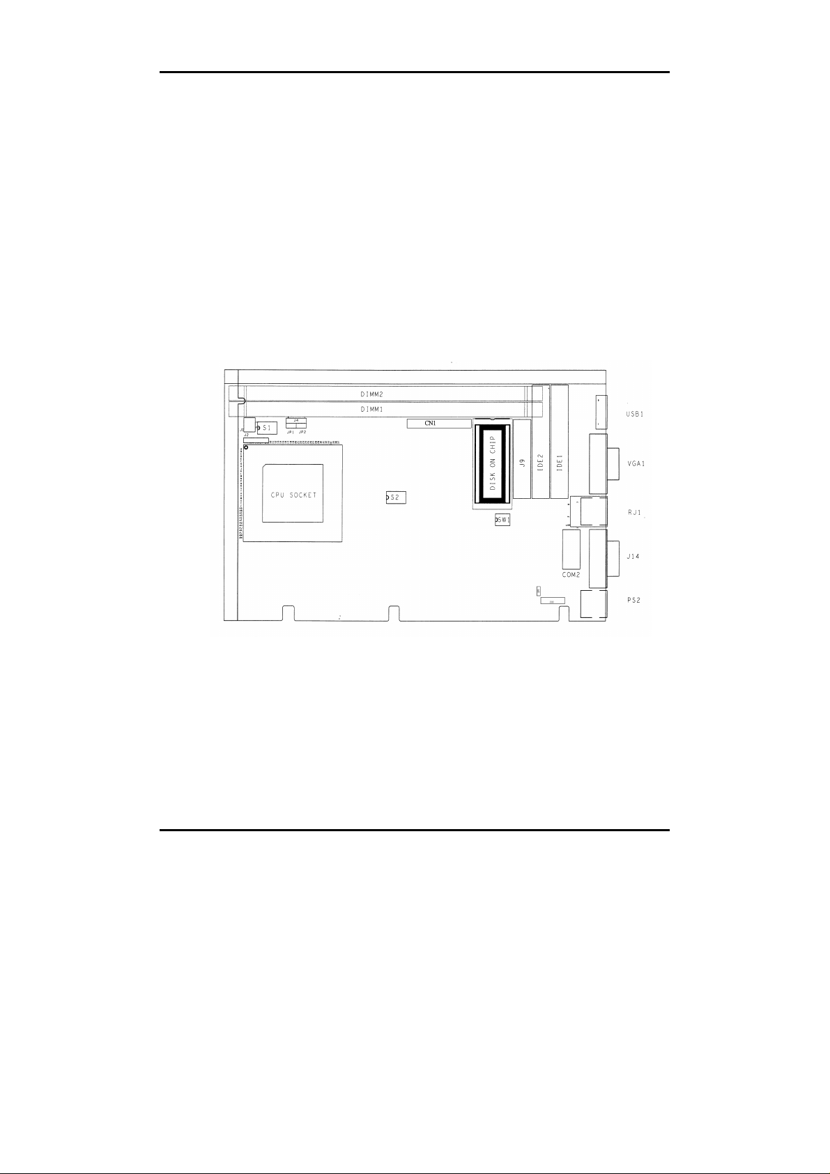
2-1 Jumpers
Jumper on the CPU board are used to select options for certain features.
To select any option, cover the jumper cap over (short) or remove it from
(open) the jumper pins according to the follows instructions.
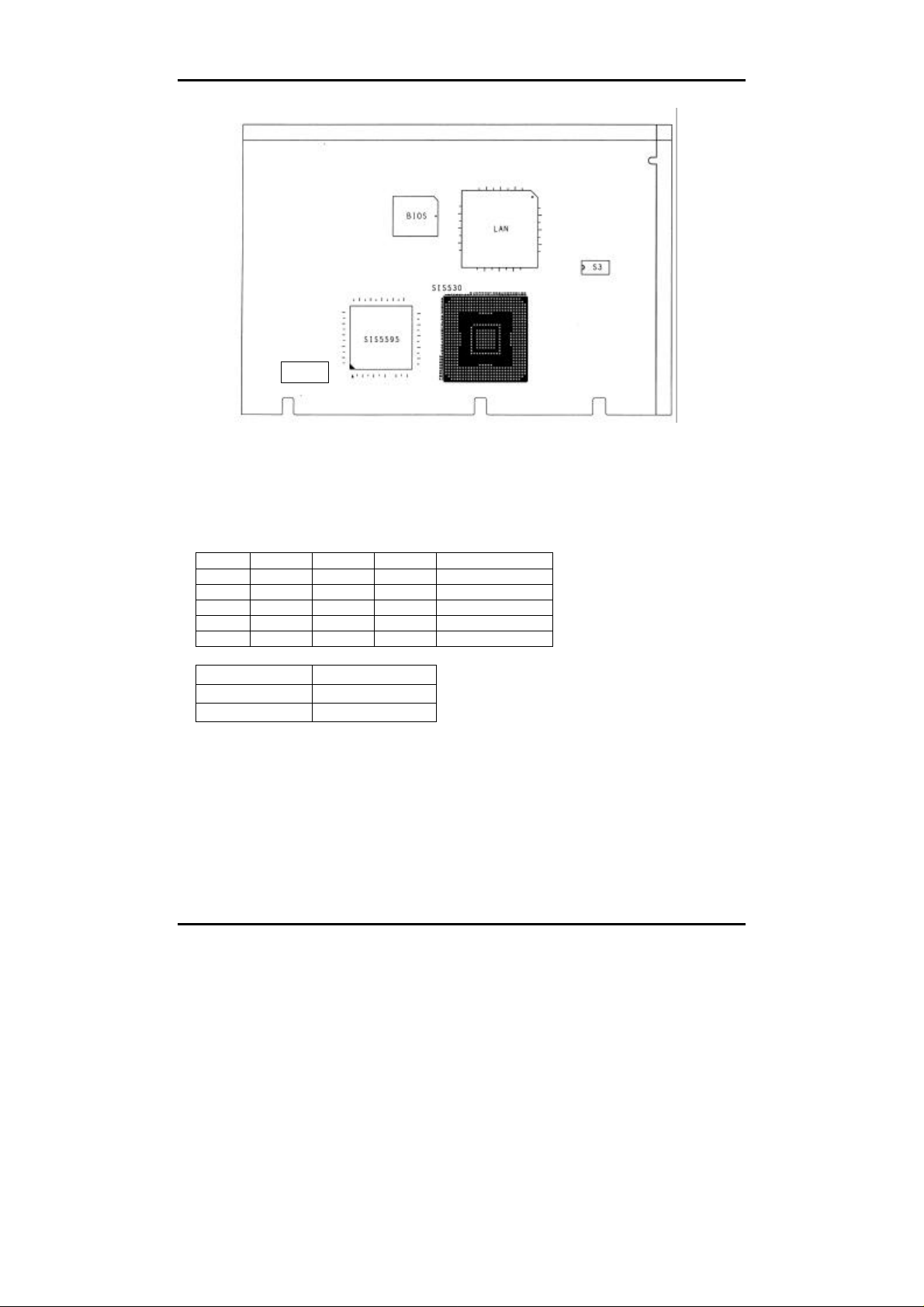
(see figure 2-1, 2-2 for jumper positions)
Figure 2-1 Jumper Positions
Switches and Connectors 2-1
Page 14
Peak 555A User's Guide
SDFD1
Figure 2-2 Jumper Positions
Jumper Setting Table (*: default setup)
DISK ON Chip
BIOS Refresh SW1.4
* ON Enabled
OFF Disabled
Switches and Connectors 2-2
Page 15

Peak 555A User's Guide
S2.5
ON
S1.1
Integrated VGA Function
S1.2
Slow Decoding OFF GUI Host Interface
OFF
S1.3
INT A Control for Panel Link
OFF
S1.4
Video Subsystem Control by BIOS
CLOCK Frequency
S2
S2.1 S2.2 S2.3 S2.4 CPU SDRAM PCI
ON ON ON ON 90.00 90.00 30.00
ON ON ON OFF 100.05 66.70 33.35
ON ON OFF ON 95.00 63.33 31.66
ON ON OFF OFF 100.00 66.66 33.33
ON OFF ON ON 100.00 75.00 30.00
ON OFF ON OFF 112.00 74.66 37.33
ON OFF OFF ON 124.00 88.86 31.00
ON OFF OFF OFF 133.30 66.70 33.32
*OFF *ON *ON *ON 66.70 66.70 33.35
OFF ON ON OFF 75.00 75.00 30.00
OFF ON OFF ON 83.30 83.30 33.30
OFF ON OFF OFF 95.00 95.00 31.66
OFF OFF ON ON 100.00 100.00 33.33
OFF OFF ON OFF 112.00 112.00 37.33
OFF OFF OFF ON 124.00 124.00 31.00
OFF OFF OFF OFF 133.30 133.30 33.33
CPU V I/O
*
3.3
OFF 2.5 (when used Intel Low power CPU)
* OFF Enabled
ON Disabled
*
Fast Decode
ON Slow Decode
Enabled
* ON Disabled
* OFF Enabled
ON Disabled
Switches and Connectors 2-3
Page 16

Peak 555A User's Guide
S1.6
OFF Normal
ON Clear CMOS Data
S3 for Intel CPU
S3.1 S3.2 S3.3 S3.4 S3.5 S3.6 S3.7 S3.8
Core/Bu
X X ON OFF ON OFF 1.5X
OFF ON X X ON OFF OFF ON 2.0X
OFF ON X X OFF ON OFF ON 2.5X
OFF ON X X OFF ON ON OFF 3.0X
*OFF *ON X X *ON *OFF *ON *OFF 3.5X
ON OFF X X OFF ON OFF ON 4.0X
S3 for AMD CPU
S3.1 S3.2 S3.3 S3.4 S3.5 S3.6 S3.7 S3.8
X X ON OFF ON OFF OFF ON 2X
X X ON OFF OFF ON OFF ON 2.5X
X X ON OFF OFF ON ON OFF 3X
X X ON OFF ON OFF ON OFF 3.5X
X X OFF ON ON OFF OFF ON 4X
X X OFF ON OFF ON OFF ON 4.5X
X X OFF ON OFF ON ON OFF 5X
X X OFF ON ON OFF ON OFF 5.5X
S3 for Rise CPU
S3.1 S3.2 S3.3 S3.4 S3.5 S3.6 S3.7 S3.8
ON OFF X X ON OFF ON OFF 1.5X
ON OFF X X ON OFF OFF ON 2.0X
ON OFF X X OFF ON OFF ON 2.5X
ON OFF X X OFF ON ON OFF 3.0X
ON OFF X X ON OFF ON OFF 3.5X
s Ratio
Core/Bu
s Ratio
Core/Bu
s
Ratio
Switches and Connectors 2-4
Page 17

Peak 555A User's Guide
2-2 Connectors
Connectors on the CPU Board provide interfaces to other devices.
Connector Function Remark
J10 Key Lock Connector
J4 Speaker Connector
IDE1 Primary IDE Connector
IDE2 Secondary IDE connector
J13 FDC Connector
J9 Printer Connector
J11 Com2 Connector 2
VGA 1 VGA Connector
USB 1 USB Connector
J14 Com1 Connector 1
PS2 PS/2 Mini DIN KBD/Mouse
J12 5 Pins KBD Connector
JP1 2 Pins HDD LED
JP3 2 Pins (RTC Clear) Connector
SDFD1 TFT LCD connector
CN1 NEXCOM PCI connector
RJ1 Lan RJ-45 connector
J2 IR connector
JP2 Reset Switch
J1 GPIO connector
J3/J5 Power regulator input connector
Connector
Switches and Connectors 2-5
Page 18

Peak 555A User's Guide
Pin definitions of connectors
• J10: Key lock
PIN No. Description
1 +5V
2 Ground
3 Ground
4 Key lock
5 Ground
• J4: Speaker
PIN No. Description
1 Speaker signal
2 Ground
3 Ground
4 +5V
• JP2: Reset Switch
PIN No. Description
1 External Reset
2 Ground
Switches and Connectors 2-6
Page 19

Peak 555A User's Guide
• IDE1/IDE2: IDE Interface Connector
PIN
Description PIN
No.
1 Reset# 2 Ground
3 Data 7 4 Data 8
5 Data 6 6 Data 9
7 Data 5 8 Data 10
9 Data 4 10 Data 11
11 Data 3 12 Data 12
13 Data 2 14 Data 13
15 Data 1 16 Data 14
17 Data 0 18 Data 15
19 Ground 20 N/C
21 DMA REQ 22 Ground
23 IOW# 24 Ground
25 IOR# 26 Ground
27 IOCHRDY 28 N/C
29 DMA ACK 30 Ground
31 Interrupt 32 N/C
33 SA1 34 N/C
35 SA0 36 SA2
37 HDC CS0# 38 HDC CS1#
39 HDD Active# 40 Ground
• RJ1: Lan connector (RJ-45)
PIN No. Description
1 TXO+
2 TXO3 RXI+
4
5
6 RXI7
8
Description
No.
75 Ω GND
75 Ω GND
75 Ω GND
75 Ω GND
Switches and Connectors 2-7
Page 20

Peak 555A User's Guide
• J13: FDC Connector
PIN
No.
Description PIN
No.
Description
1 Ground 2 Density Select
3 Ground 4 N/C
5 Ground 6 N/C
7 Ground 8 Index#
9 Ground 10 Motor Enable
A#
11 Ground 12 Drive Select
B#
13 Ground 14 Drive Select
A#
15 Ground 16 Motor Enable
B#
17 Ground 18 Direction#
19 Ground 20 Step#
21 Ground 22 Write Data#
23 Ground 24 Write Gate#
25 Ground 26 Track 0#
27 Ground 28 Write Protect#
29 N/C 30 Read Data#
31 Ground 32 Head Side
Select#
33 N/C 34 Disk Change#
• J9: Parallel Port Connector
PIN
No.
Description PIN
No.
Description
1 Strobe# 2 Data 0
3 Data 1 4 Data 2
5 Data 3 6 Data 4
7 Data 5 8 Data 6
9 Data 7 10 Acknowledge
11 Busy 12 Paper Empty
13 Printer Select 14 Auto Form
Feed#
15 Error# 16 Initialize
17 Printer Select
18 Ground
IN#
19 Ground 20 Ground
Switches and Connectors 2-8
Page 21
Peak 555A User's Guide
21 Ground 22 Ground
23 Ground 24 Ground
25 Ground
• J14: Serial Port Connector -D-Sub 9-Pin
PIN No. Description
1 Data Carrier Detect (DCD)
2 Receive Data (RXD)
3 Transmit Data (TXD)
4 Data Terminal Ready (DTR)
5 Ground (GND)
6 Data Set Ready (DSR)
7 Request to Send (RTS)
8 Clear to Send (CTS)
9 Ring Indicator (RI)
• VGA1: VGA Connector
PIN No. Description
1 RED
2 Green
3 Blue
4 NC
5 GND
6 GND
7 GND
8 GND
9 +5V
10 GND
11 NC
12 Display data channel data
13 Horizontal Sync
14 Vertical Sync
15 Display Data Channel Clock
• USB1: USB Connector
PIN No. Description
1 VCC
2 SBD13 SBD1+
4 SBD0-
Switches and Connectors 2-9
Page 22

Peak 555A User's Guide
5 SBD0+
6 Ground
• PS2: 6-Pin Mini-DIN Keyboard Connector (PS/2 Type)
PIN No. Description
1 Keyboard Data
2 Mouse/Data
3 Ground
4 +5V
5 Keyboard Clock
6 Mouse/Data
• J12: Keyboard Connector
PIN No. Description
1 Keyboard Clock
2 Keyboard Data
3 N/C
4 Ground
5 +5V
• JP1: IDE LED Connector
PIN No. Description
1 2 +
• J11: Serial Port Connector (2*5 pin 2.54mm connector)
PIN No. Description
1 Data Carrier Detect (DCD)
2 Receive Data (RXD)
3 Transmit Data (TXD)
4 Data Terminal Ready (DTR)
5 Ground (GND)
6 Data Set Ready (DSR)
7 Request to Send (RTS)
8 Clear to Send (CTS)
9 Ring Indicator (RI)
10 +5V
Switches and Connectors 2-10
Page 23

Peak 555A User's Guide
• Mini PCI Connector
1 5V 2 Data 0
3 Data 1 4 Data 2
5 Data 3 6 Data 4
7 Data 5 8 Data 6
9 Data 7 10 Ground
11 5V 12 Data 8
13 Data 9 14 Data 10
15 Data 11 16 Data 12
17 Data 13 18 Data 14
19 Data 15 20 Ground 16
21 5V 22 Data 18
23 Data 17 24 Data 20
25 Data 19 26 Data 22
27 Data 21 28 Data 24
29 Data 23 30 Ground
31 5V 32 Data 26
33 Data 25 34 Data 28
35 Data 27 36 Data 30
37 Data 29 38 Data 32
39 Data 31 40 Ground
41 5V 42 CB/E0
43 CB/E1 44 CB/E2
45 CB/E3 46 PAR
47 FRAME# 48 TRDY#
49 IRDY# 50 Ground
51 5V 52 STOP#
53 DEVSEL# 54 PERR#
55 SERR# 56 REQ 0#
57 GNT 0# 58 REQ 2#
59 GNT 2# 60 Ground
61 PCI CLOCK 62 PC1CLK
63 PCI RESET# 64 PLOCK#
65 INTA# 66 INTB#
67 INTC# 68 INTC#
Switches and Connectors 2-11
Page 24
Peak 555A User's Guide
J2 FAN
J3
J2 FAN
J3
J2: IR
Pin No. Description
1: VCC
2: IRRXH (FAST IR)
3: IRRX
4: GND
5: IRTX
J4 Power
J4 Power
Connector
Connector
S1
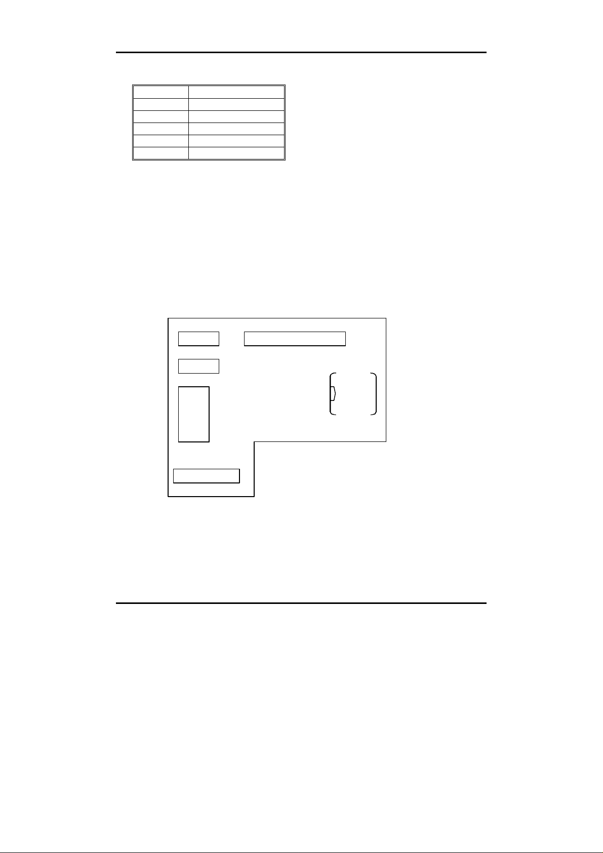
Figure 2-3 Power Module
Switches and Connectors 2-12
Page 25

Peak 555A User's Guide
Vcore Voltage
S1.1 S1.2 S1. 3 S1.4 S1.5 S1.6
1.9V OFF OFF OFF OFF OFF OFF
2.2V ON OFF OFF OFF OFF OFF
*2.8V *OFF *ON *OFF *OFF *OFF *OFF
2.9V OFF OFF ON OFF OFF OFF
3.2V OFF OFF OFF ON OFF OFF
3.3V OFF OFF OFF OFF ON OFF
.45V OFF OFF OFF OFF OFF ON
V I/O
S1.7
*3.3V *OFF
3.45V ON
CPU VIO
S1.8 S1.9
3.45V OFF OFF
*3.3V *ON *OFF
2.5V OFF ON
Standby Power
S1.10
On When AT power
Off When ATX power
J2: FAN Power
1 12V
2 FAN sensor
3 GND
J4: 5V Power input
1 5V
2 5V
3 GND
4 GND
J3: Standby By Power input/ATX power control pin
1 SB 5V
2 Power on
3 GND
Switches and Connectors 2-13
Page 26

Peak 555A User's Guide
SW1.1
SCSI Terminator
SW1.2
8/16Bit SCSI
*ON
OFF Disabled OFF 8
AIC-78809
U1
SW1
SCSI 68 Pin Connector
Figure 2-4 SCSI Connector
Enabled *ON 16
Switches and Connectors 2-14
Page 27

Peak 555A User's Guide
• JP3 ATX Power Bottom
1 Ground 2 Ground
3 Ground 4 Ground
5 Ground 6 Ground
7 Ground 8 Ground
9 Ground 10 Ground
11 Ground 12 Ground
13 Ground 14 Ground
15 Ground 16 Ground
17 TRMPWR 18 TRMPWR
19 NC 20 Ground
21 Ground 22 Ground
23 Ground 24 Ground
25 Ground 26 Ground
27 Ground 28 Ground
29 Ground 30 Ground
31 Ground 32 Ground
33 Ground 34 Ground
35 SCD 12 36 SCD 13
37 SCD 14 38 SCD 15
39 SCDP1# 40 SCD 0
41 SCD 1 42 SCD 2
43 SCD 3 44 SCD 4
45 SCD 5 46 SCD 6
47 SCD 7 48 SCDP0#
49 Ground 50 Ground
51 TRMPWER 52 TRMPWER
53 NC 54 Ground
55 SATN# 56 Ground
57 SBSY# 58 SACK#
59 SRST# 60 SMSG#
61 SSEL# 62 SCD#
63 SREQ# 64 SIO#
65 SCD 8 66 SCD 9
67 SCD 10 68 SCD 11
Switches and Connectors 2-15
Page 28

Peak 555A User's Guide
Chapter 3
Capability Expanding
This chapter explains how you can expand capability of your CPU board
in such aspects as system memory, cache memory, and CPU.
3-1 System Memory
Your system DRAM is provided by 168 pin DIMM's (Dual In-line
Memory Modules) on the CPU board. The CPU board contains two
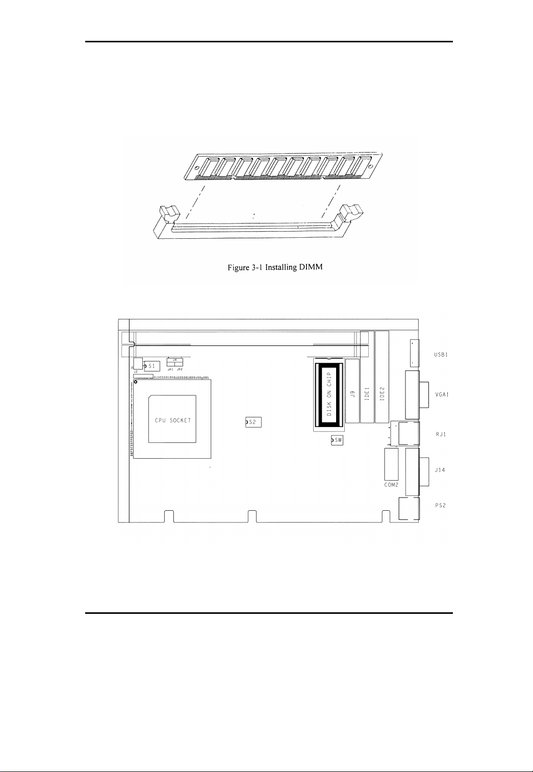
memory banks corresponding to connector DIMM1 and DIMM2.
The table below shows possible DIMM configurations for the memory
banks and the figure helps you correctly install the DIMM modules.
See Figure 3-2 for memory bank's location.
DIMM 1 DIMM 2 Total Memory
16MB -- 16MB
16MB 16MB 32MB
32MB -- 32MB
32MB 32MB 64MB
64MB -- 64MB
64MB 64MB 128MB
128MB -- 128MB
128MB 128MB 256MB
256MB -- 256MB
256MB 256MB 516MB
Capability Expanding 3-1
Page 29
Peak 555A User's Guide
DIMM (Bank 1)
DIMM (Bank 0)
The DIMM used SDRAM memory. Please be noted that if the 100MHz
CPU external lock is turned on, the memory should be SDRAM only and
PC-100 complied.
Figure 3-2 Memory Banks
Capability Expanding 3-2
Page 30

Peak 555A User's Guide
3.2 The Cache Memory
The Peak 555A series only support the high speed pipeline burst SRAM.
The default L2 Cache is 512 KB.
3.3 Change CPU
The Peak 555A uses the 321 pin PGA socket rather than the ZIF socket,
so it needs force to push or pull the CPU into or out from the socket.
Normally, you have to use some tools to pull the CPU out from the
socket. To put on a new CPU, please place the new CPU on the
middle of the socket, orienting its beveled corner to line up with the
socket’s beveled corner. Make sure the pins of the CPU fit evenly to
the socket openings, then press the CPU until all the pins fit into the
socket. Be sure to re-arrange the DIP switch setting for the correct
clock and Core/Bus ratio. The Peak 555A supports many kinds of
CPU’s, please refer to the DIP switch setting table for the right
arrangement.
Capability Expanding 3-3
Page 31

Peak 555A User’s Guide
Chapter 4
AWARD BIOS Setup
Award's BIOS ROM has a built-in Setup program that allows users to modify
the basic system configuration. This type of information is stored in
battery-backed RAM (CMOS RAM) so that it retains the Setup information
when the power is turned off.
Entering Setup
Power on the computer and press <Del> immediately will allow you to enter
Setup. The other way to enter Setup is to power on the computer, when the
below message appears briefly at the bottom of the screen during the POST
(Power On Self Test), press <Del> key or simultaneously press <Ctrl>, <Alt>,
and <Esc> keys.
TO ENTER SETUP BEFORE BOOT PRESS <CTRL-ALT-ESC> OR
<DEL> KEY
If the message disappears before you respond and you still wish to enter
Setup, restart the system to try again by turning it OFF then ON or pressing
the "RESET" button on the system case. You may also restart by
simultaneously pressing <Ctrl>, <Alt>, and <Delete> keys. If you do not press
the keys at the correct time and the system does not boot, an error message
will be displayed and you will again be asked to,
PRESS <F1> TO CONTINUE, <CTRL-ALT-ESC> OR <DEL> TO
ENTER SETUP
BIOS Setup 4-1
Page 32

Peak 555A User’s Guide
Control Keys
Up arrow Move to previous item
Down arrow Move to next item
Left arrow Move to the item in the left hand
Right arrow Move to the item in the right hand
Esc key Main Menu -- Quit and not save changes into CMOS
Status Page Setup Menu and Option Page Setup Menu -- Exit current page and
return to Main Menu
PgUp / “+”
key
PgDn /
“−“ key
F1 key General help, only for Status Page Setup Menu and Option Page Setup Menu
(Shift)F2 key Change color from total 16 colors. F2 to select color forward, (Shift) F2 to select
F3 key Reserved
F4 key Reserved
F5 key Restore the previous CMOS value from CMOS, only for Option Page Setup
F6 key Load the default CMOS value from BIOS default table, only for Option Page
F7 key Load the Setup default , only for Option Page Setup Menu
F8 key Reserved
F9 key Reserved
F10 key Save all the CMOS changes, only for Main Menu
Increase the numeric value or make changes
Decrease the numeric value or make changes
color backward
Menu
Setup Menu
BIOS Setup 4-2
Page 33

Peak 555A User’s Guide
Getting Help
Main Menu
The on-line description of the highlighted setup function is displayed at the
bottom of the screen.
Status Page Setup Menu/Option Page Setup Menu
Press F1 to pop up a small help window that describes the appropriate keys to
use and the possible selections for the highlighted item. To exit the Help
Window press <F1> or <Esc>.
BIOS Setup 4-3
Page 34
Peak 555A User’s Guide
The Main Menu
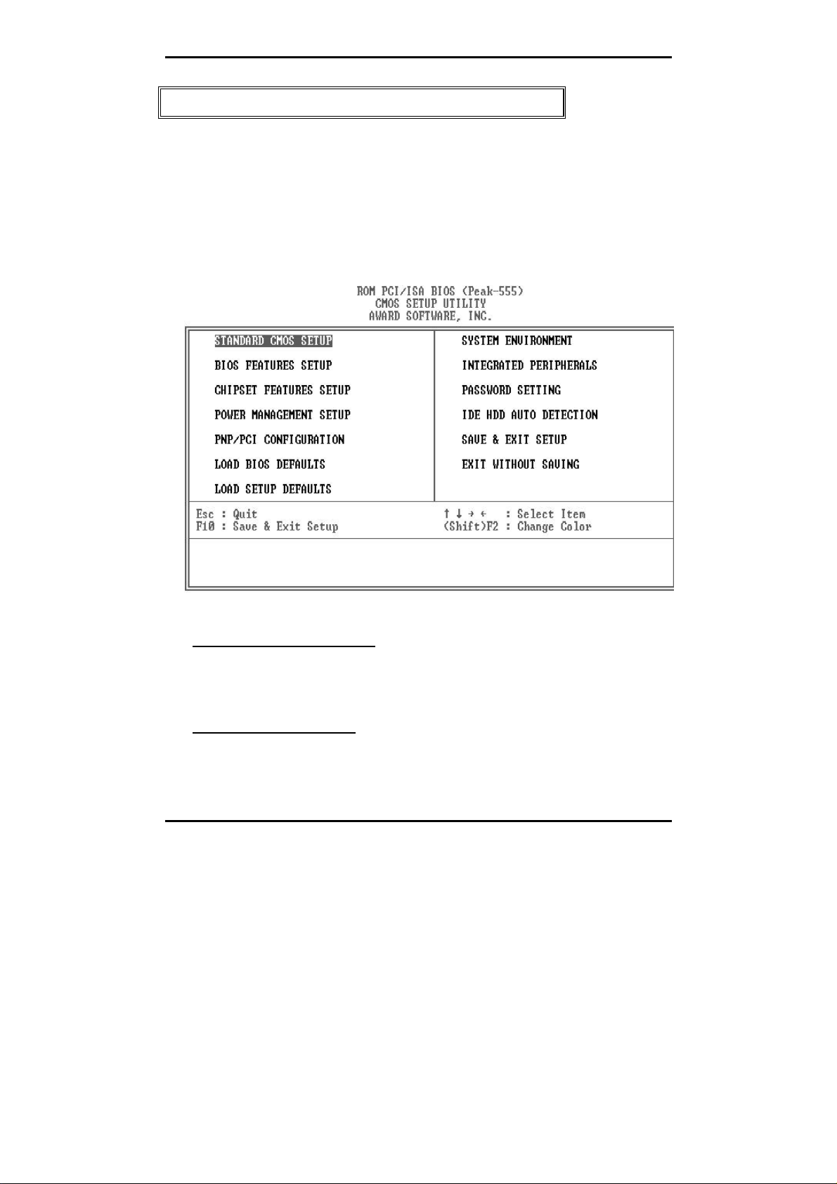
Once you enter Award BIOS CMOS Setup Utility, the Main Menu (Figure 1)
will appear on the screen. The Main Menu allows you to select from ten setup
functions and two exit choices. Use arrow keys to select among the items and
press <Enter> to accept or enter the sub-menu.
Figure 1 Main Menu
Standard CMOS setup
This setup page includes all the items in a standard compatible BIOS.
See Page 4-7 to Page 4-10 for details.
BIOS features setup
This setup page includes all the items of Award special enhanced
features. See Page 4-11 to Page 4-15 for details.
BIOS Setup 4-4
Page 35

Peak 555A User’s Guide
Chipset features setup
This setup page includes all the items of chipset special features. See
Page 4-17 to Page 4-21 for details.
Power Management setup
This category determines how much power consumption for system after
selecting below items. Default value is Disable. See Page 4-22 to Page
4-26 for details.
PNP/PCI CONFIGURATION
This category specifies the assignment of all the IRQ’s and DMA’s
See Page 4-27 to Page 4-28 for details.
Load BIOS defaults
BIOS defaults indicates the most appropriate value of the system
parameter which the system would be in minimum performance. The
OEM manufacturer may change the defaults through MODBIN before the
binary image burn into the ROM.
Load setup defaults
Chipset defaults indicates the values required by the system for the
maximum performance. The OEM manufacturer may change to defaults
through MODBIN before the binary image burn into the ROM.
Integrated Peripherals System Environment
This category allows you to set up all the on board I/O controllers like IDE,
SCSI, FDC, etc,. See Page 4-30 to Page 4-32
Password Setting
Change, set, or disable password of supervisor or user. It allows you to
limit access to the system and Setup, or just to Setup. See Page 4-33 for
details.
BIOS Setup 4-5
Page 36

Peak 555A User’s Guide
IDE HDD auto detection
Automatically configure hard disk parameters. See Page 4-34.
Save & Exit Setup
Save CMOS value changes to CMOS and exit setup.
Exit without saving
Abandon all CMOS value changes and exit setup.
BIOS Setup 4-6
Page 37
Peak 555A User’s Guide
HARD DISKS TYPE SIZE CYLS HEAD PRECOMP LANDZ SECTOR MODE
Total Memory:
Standard CMOS Setup Menu
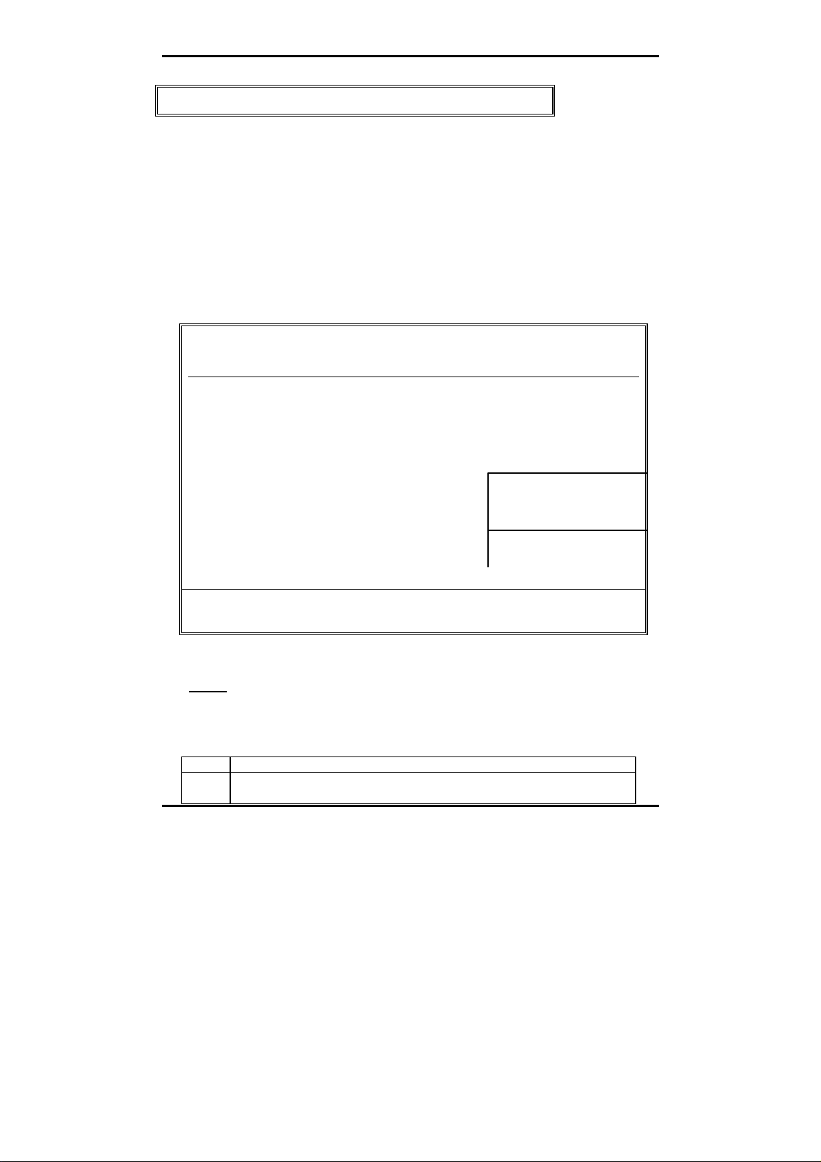
The items in Standard CMOS Setup Menu are divided into 10 categories.
Each category includes no, one or more than one setup items. Use the arrow
keys to highlight the item and then use the <PgUp> or <PgDn> keys to select
the value you want in each item.
Figure 2 Standard CMOS Setup Menu (Support Enhanced IDE)
ROM PCI / ISA BIOS (Peak-555)
STANDARD CMOS SETUP
AWARD SOFTWARE, INC.
Date (mm:dd:yy) : Mon, Dec 14 1998
Time (hh:mm:ss) : 17:58: 3
Primary Master : AUTO 0 0 0 0 0 0 AUTO
Primary Slave : AUTO 0 0 0 0 0 0 AUTO
Secondary Master : AUTO 0 0 0 0 0 0 AUTO
Secondary Slave : AUTO 0 0 0 0 0 0 AUTO
Drive A : 1.44M, 3.5 in.
Drive B : None
Floppy 3 Mode Support : Disabled
Base Memory:
640K
LCD&CRT : Auto Extended Memory: 60416K
Halt On : All , But keyboard Other Memory: 380K
61440K
ESC : Quit ↑ ↓ → ← : Select Item PU / PD / + / - : Modify
F1 : Help (Shift) F2 : Change Color
Date
The date format is <day>, <date> <month> <year>. Press <F3> to show the
calendar.
Day The day of week, from Sun to Sat, determined by the BIOS, is read only
date The date, from 1 to 31 (or the maximum allowed in the month), can key in the
numerical / function key
BIOS Setup 4-7
Page 38

Peak 555A User’s Guide
month The month, Jan through Dec
year The year, depend on the year of BIOS
Time
The time format is <hour> <minute> <second>. which accepts both
function key or numerical key The time is calculated based on the 24-hour
military-time clock. For example, 1 p.m. is 13:00:00.
Primary Master/Primary Slave
The categories identify the types of drives that have been installed in the
computer. There are 45 predefined types and 2 user definable types are
for Enhanced IDE BIOS. Type 1 to Type 45 are predefined. Type User is
user-definable.
Press PgUp/<+> or PgDn/<−> to select a numbered hard disk type or type
the number and press <Enter>. Note that the specifications of your drive
must match with the drive table. The hard disk will not work properly if
you enter improper information for this category. If your hard disk drive
type is not matched or listed, you can use Type User to define your own
drive type manually.
If you select Type User, related information is asked to be entered to the
following items. Enter the information directly from the keyboard and
press <Enter>. This information should be provided in the documentation
from your hard disk vendor or the system manufacturer.
If the controller of HDD interface is ESDI, the selection shall be “Type 1”.
If the controller of HDD interface is SCSI, the selection shall be “None”.
If the controller of HDD interface is CD-ROM, the selection shall be
“None”.
CYLS. number of cylinders
HEADS number of heads
PRECOMP write precom
LANDZONE landing zone
SECTORS number of sectors
MODE HDD access mode
If a hard disk has not been installed select NONE and press <Enter>.
BIOS Setup 4-8
Page 39

Peak 555A User’s Guide
Drive A type/Drive B type
The category identifies the types of floppy disk drive A or drive B that
have been installed in the computer.
None No floppy drive installed
360K, 5.25 in 5-1/4 inch PC-type standard drive; 360 kilobyte
1.2M, 5.25 in 5-1/4 inch AT-type high-density drive; 1.2 megabyte
720K, 3.5 in 3-1/2 inch double-sided drive; 720 kilobyte capacity
1.44M, 3.5 in 3-1/2 inch double-sided drive; 1.44 megabyte
2.88M, 3.5 in 3-1/2 inch double-sided drive; 2.88 megabyte
Video
The category selects the type of adapter used for the primary system
monitor that must match your video display card and monitor. Although
secondary monitors are supported, you do not have to select the type in
Setup.
You have two ways to boot up the system:
1. When VGA as primary and monochrome as secondary, the selection of
the
video tape is “VGA Mode”.
2. When monochrome as primary and VGA as secondary, the selection of
the
video type is “Monochrome Mode”.
EGA/VGA Enhanced Graphics Adapter/Video Graphics Array. For EGA,
VGA, SEGA, or PGA monitor adapters.
CGA 40 Color Graphics Adapter, power up in 40 column mode
CGA 80 Color Graphics Adapter, power up in 80 column mode
MONO Monochrome adapter, includes high resolution monochrome
adapters
capacity
capacity
capacity
capacity
BIOS Setup 4-9
Page 40

Peak 555A User’s Guide
Error halt
The category determines whether the computer will stop if an error is
detected during power up.
No errors Whenever the BIOS detects a non-fatal error the system will be stopped
All errors The system boot will not be stopped for any error that may be detected.
All,But Keyboard The system boot will not stop for a keyboard error; it will stop for all other
All, But Diskette The system boot will not stop for a disk error; it will stop for all other errors.
All, But Disk/Key The system boot will not stop for a keyboard or disk error; it will stop for all
and you will be prompted.
errors.
other errors.
Memory
The category is display-only which is determined by POST (Power On Self
Test) of the BIOS.
Base Memory
The POST of the BIOS will determine the amount of base (or
conventional) memory installed in the system. The value of the base
memory is typically 512K for systems with 512K memory installed on
the motherboard, or 640K for systems with 640K or more memory
installed on the motherboard.
Extended Memory
The BIOS determines how much extended memory is present during
the POST. This is the amount of memory located above 1MB in the
CPU's memory address map.
Other Memory
This refers to the memory located in the 640K to 1024K address
space. This is memory that can be used for different applications.
DOS uses this area to load device drivers to keep as much base
memory free for application programs. Most use for this area is
Shadow RAM.
Total Memory
System total memory is the sum of basic memory, extended memory,
and other memory.
BIOS Setup 4-10
Page 41
Peak 555A User’s Guide
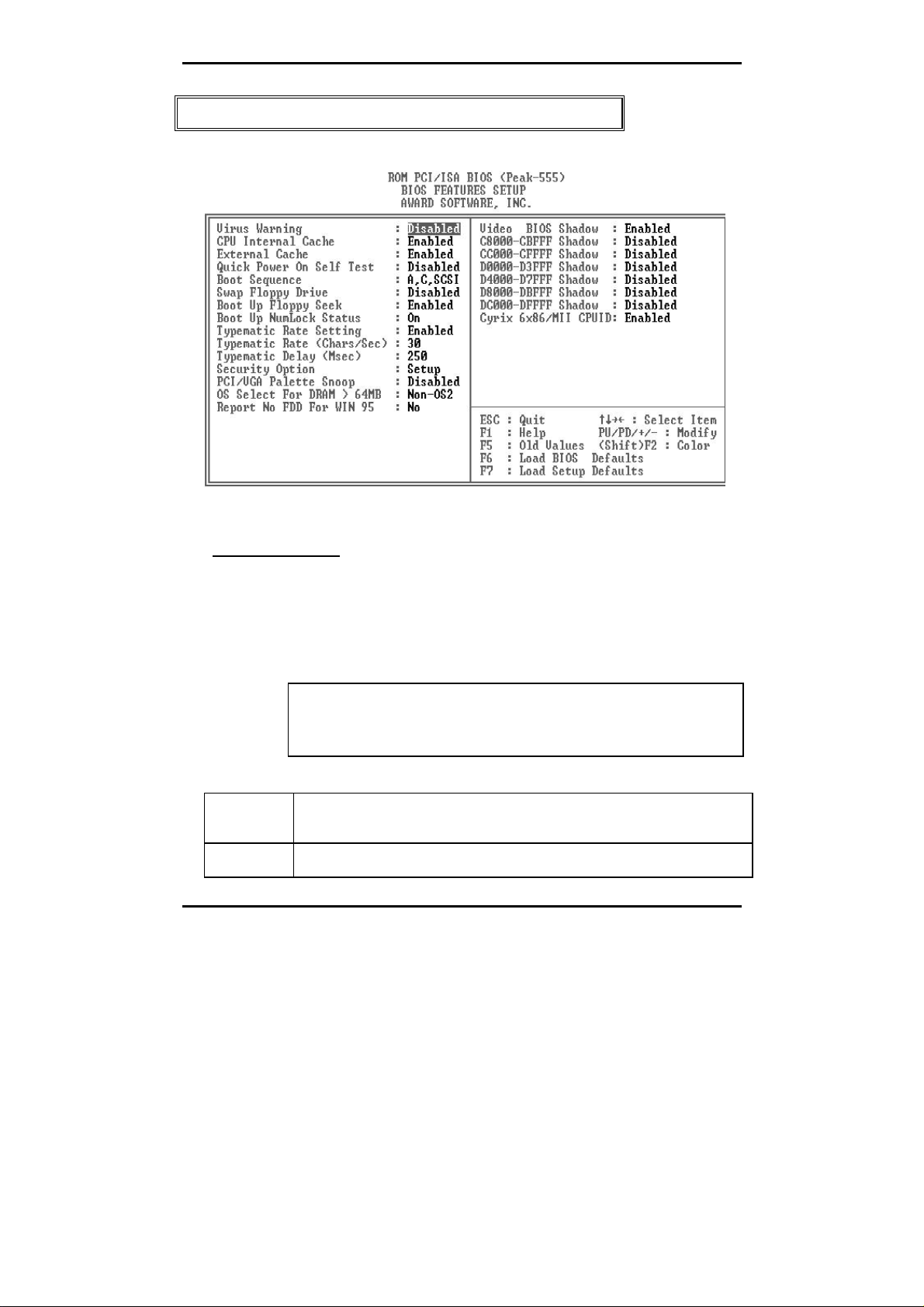
BIOS Features Setup Menu
Virus Warning
This category flashes on the screen. During and after the system boots
up, any attempt to write to the boot sector or partition table of the hard
disk drive will halt the system and the following error message will appear,
in the mean time, you can run an anti-virus program to locate the
problem.
! WARNING !
Disk boot sector is to be modified
Type "Y" to accept write or "N" to abort write
Award Software, Inc.
Enabled Activates automatically when the system boots up causing a warning
message to appear when anything attempts to access the boot sector or
hard disk partition table.
Disabled No warning message to appear when anything attempts to access the
boot sector or hard disk partition table.
BIOS Setup 4-11
Page 42

Peak 555A User’s Guide
Note: This function is available only for DOS and other OSes that do not trap
INT13.
CPU Internal Cache/External Cache
These two categories speed up memory access. However, it depends on
CPU/chipset design. The default value is Enable. If your CPU without
Internal Cache then this item “CPU Internal Cache” will not be show.
Enabled Enable cache
Disabled Disable cache
Quick Power On Self Test
This category speeds up Power On Self Test (POST) after you power on
the computer. If it is set to Enable, BIOS will shorten or skip some check
items during POST.
Enabled Enable quick POST
Disabled Normal POST
Boot Sequence
This category determines which drive computer searches first for the disk
operating system (i.e., DOS). Default value is A,C.
C,A System will first search for hard disk drive then floppy disk drive.
A,C System will first search for floppy disk drive then hard disk drive.
Note: This function is only available for IDE type
For SCSI type is always boot from A.
Boot Up Floppy Seek
During POST, BIOS will determine if the floppy disk drive installed is 40
or 80 tracks. 360K type is 40 tracks while 760K, 1.2M and 1.44M are all
80 tracks.
Enabled BIOS searches for floppy disk drive to determine if it is 40 or 80
tracks. Note that BIOS can not tell from 720K, 1.2M or 1.44M drive
type as they are all 80 tracks.
BIOS Setup 4-12
Page 43

Peak 555A User’s Guide
Disabled BIOS will not search for the type of floppy disk drive by track
number. Note that there will not be any warning message if the
drive installed is 360K.
Boot Up NumLock Status
The default value is On.
On Keypad is number keys
Off Keypad is arrow keys
Typematic Rate Setting
This determines the typematic rate.
Enabled Enable typematic rate and typematic delay
programming
Disabled Disable typematic rate and typematic delay
programming. The system BIOS will use default
value of this 2 items and the default is controlled by
keyboard.
Typematic Rate (Chars/Sec)
6 6 characters per second
8 8 characters per second
10 10 characters per second
12 12 characters per second
15 15 characters per second
20 20 characters per second
24 24 characters per second
30 30 characters per second
Typematic Delay (Msec)
When holding a key, the time between the first and second character
displayed.
250 250 msec
500 500 msec
750 750 msec
1000 1000 msec
BIOS Setup 4-13
Page 44

Peak 555A User’s Guide
Security Option
This category allows you to limit access to the system and Setup, or just
to Setup.
System The system will not boot and access to Setup will be denied if the
correct password is not entered at the prompt.
Setup The system will boot, but access to Setup will be denied if the correct
password is not entered at the prompt.
Note: To disable security, select PASSWORD SETTING at Main Menu and
then you will be asked to enter password. Do not type anything and just press
<Enter>, it will disable security. Once the security is disabled, the system will
boot and you can enter Setup freely.
PCI/VGA Palette Snoop
It determines whether the MPEG ISA/VESA VGA Cards can work with
PCI/VGA or
not.
Enabled When PCI/VGA working with MPEG ISA/VESA
VGA Card.
Disable
d
When PCI/VGA not working with MPEG ISA/VESA
VGA Card.
OS Select for DRAM > 64MB
This segment is specifically created for OS/2 when DRAM is larger than
64MB. If your operating system is OS/2 and DRAM used is larger the 64MB,
you have to select “OS 2”, otherwise, non-OS2, default is NON-OS2.
Video BIOS Shadow
It determines whether video BIOS will be copied to RAM, however, it is
optional from chipset design. Video Shadow will increase the video
speed.
BIOS Setup 4-14
Page 45

Peak 555A User’s Guide
Enabled Video shadow is enabled
Disabled Video shadow is disabled
BIOS Setup 4-15
Page 46

Peak 555A User’s Guide
C8000 - CFFFF Shadow/D8000 - DFFFF Shadow
These categories determine whether optional ROM will be copied to RAM
by 16K byte or 32K byte per/unit and the size depends on chipset.
Enabled Optional shadow is enabled
Disabled Optional shadow is disabled
Note: 1. for C8000-DFFFF option-ROM on PCI BIOS , BIOS will
automatically enable the shadow RAM. User does not have to
select the item.
2. IDE second channel control:
Enable : enable secondary IDE port and BIOS will assign IRQ15
for this port.
Disable: disable secondary IDE port and IRQ15 is available for
other device.
The item is optional only for PCI BIOS.
3. Some of the sound cards have an onboard CD-ROM controller
which uses IDE Secondary Port. In order to avoid PCI
IDE conflict, the IDE secondary channel control has to select
“disable” then CD- ROM can work.
BIOS Setup 4-16
Page 47

Peak 555A User’s Guide
Chipset Features Setup Menu
Since the features in this section are related to the chipset in the CPU board
and all are optimized, you are not recommended to change the default
settings in the setup table, unless you know very detailed of the chipset
features.
ROM PCI/ISA BIOS (Peak-555)
CHIPSET FEATURES SETUP
AWARD SOFTWARE, INC.
Refresh Rate Control : 15-6us System BIOS Cacheable : Enabled
Ref/Act Command Delay : 6T Video BIOS Cacheable : Enabled
Refresh Queue Depth : 12 Memory Hole at 15M-16M :
Disabled
RAS Precharge Time : 3T PCI Post Write Buffer :
Disabled
RAS to CAS Delay : 3T PCI Delayed Transaction :
Disabled
ISA Bus Clock Frequency : PCICLK/4 Auto Detect DIMM/PCI
Clk
Starting Point of Paging : 1T Spread Spectrum :
NA# Enable : Disabled
L2 Cache Burst RD Cycle : Enabled
Asyn/Sync Mode
CPU/DRAM
SDRAM CAS Latency : 2T
:
Asynchronous
SDRAM WR Retire Rate : x-1-1-1
DRAM Opt RAS
: Disabled
Precharge
PCI Peer Concurrency : Enabled
Read Prefetch Memory
: Enabled
RD
Assert TRDY After Prefet : V
CPU to PCI Burst Mem.
: Enabled
ESC : Quit ↑ ↓ → ←: Select Item
F1 : Help PU/PD/+/- : Modify
WR
CPU to PCI Post Write : Enabled
:
AGP Aperture Size : 4MB
F5 : Old Values (Shift) F2 : Color
F6 : Load BIOS Defaults
F7 : Load Setup Defaults
:
Disabled
Disabled
BIOS Setup 4-17
Page 48

Peak 555A User’s Guide
Auto Configuration
Auto Configuration selects predetermined optimal values of chipset
parameters. When Disabled, chipset parameters revert to setup
information stored in CMOS. Many fields in this screen are not available
when Auto Configuration is Enabled.
The Choice: Enabled (Default), Disabled.
Note: When this item is enabled, the pre-defined items will become
SHOW-ONLY.
DRAM Timimg
The DRAM timing is controlled by the DRAM Timing Registers. The
timings programmed into this register are dependent on the system
design. Slower rates may be required in certain system designs to
support loose layouts or slower memory.
60ns DRAM Timing Type.
70ns (Default) DRAM Timing Type.
DRAM Read Burst (EDO/FP)
This sets the timing for burst mode reads from two different
DRAM(EDO/FPM). Burst read and write requests are generated by the
CPU in four separate parts. The first part provides the location within the
DRAM where the read or write is to take place while the remaining three
parts provide the actual data. The lower the timing numbers, the faster
the system will address memory.
x222/x333 Read DRAM (EDO/FPM) timings are 2-2-2/3-3-3
x333/x444 (Default) Read DRAM (EDO/FPM) timings are 3-3-3/4-4-4
x444/x444 Read DRAM (EDO/FPM) timings are 4-4-4/4-4-4
DRAM Write Burst Timing
This sets the timing for burst mode writes from DRAM. Burst read and
write requests are generated by the CPU in four separate parts. The first
part provides the location within the DRAM where the read or write is to
take place while the remaining three parts provide the actual data. The
lower the timing numbers, the faster the system will address memory.
x222 Write DRAM timings are 2-2-2-2
x333 (Default) Write DRAM timings are 3-3-3-3
x444 Write DRAM timings are 4-4-4-4
BIOS Setup 4-18
Page 49

Peak 555A User’s Guide
Fast EDO Lead Off
The item allows you to select the Fast EDO Lead Off or not to enhance
the performance. The Choice: Enabled, Disabled (Default).
Refresh RAS# Assertion
This item allows you to select the type of DRAM refresh clock delay.
4Clks The timing type.
5Clks (Default) The timing type.
Fast RAS To CAS Delay
This field lets you insert a timing delay to get a faster performance
between the Row Address Strobe (RAS) to Column Address Strobe
(CAS) strobe signals, used when DRAM is written to, read from, or
refreshed.
2 The timing delay
3 (Default) The timing delay.
DRAM Enhanced Paging
This item allows you to determine whether to keep the page open until a
page/row miss or use additional information to keep the DRAM page open
when host may be “right back”.
The Choice: Enabled (Default), Disabled.
Fast MA To RAS# Delay
This item allows you to select the DRAM Row Miss timing. Note: the
timing adjustments are independent of DLT timing adjustment.
1 One clocks. (MA set up to RAS# assertion)
2 Two clocks (Default).
BIOS Setup 4-19
Page 50

Peak 555A User’s Guide
SDRAM (CAS Lat/RAS-to-CAS)
This item allows you to select the CAS# latency for all SDRAM cycles and
RAS# to CAS# delay.
2/2 The timing type.
3/3 (Default) The timing type.
SDRAM Speculative Read
This item is capable of allowing a DRAM read request to be generated
slightly before the address has been fully decoded. This can reduce all
read latencies.
More simply, the CPU will issue a read request and included with this
request is the place (address) in memory where the desired data is to be
found. This request is received by the DRAM controller. When it is
enabled, the controller will issue the read command slightly before it has
finished determining the address.
The Choice: Enabled, Disabled (Default).
System BIOS Cacheable
Select Enabled allows caching of the system BIOS ROM at
F000h-FFFFFh, resulting in better system performance. However, if any
program writes to this memory area, a system error may result.
Enabled BIOS access cached
Disabled (Default) BIOS access not cached
Video BIOS Cacheable
Select Enabled allows caching of the video BIOS ROM at
C0000h-F7FFFh, resulting in better video performance. However, if any
program writes to this memory area, a system error may result.
Enabled Video BIOS access cached
Disabled (Default) Video BIOS access not cached
BIOS Setup 4-20
Page 51

Peak 555A User’s Guide
8 Bit I/O Recovery Time
The recovery time is the length of time, measured in CPU clocks, which
the system will delay after the completion of an input/output request. This
delay takes place because the CPU is operationg so much faster than the
input/output bus that the CPU must be delayed to allow for the completion
of the I/O. This itm allows you to detemine the recovery time allowed for
8 bit I/O. Choices are from NA, 1 (Default) to 8 CPU clocks.
16 Bit I/O Recovery Time
This item allows you to determine the recovery time allowed for 16 bit I/O.
Choices are NA, 1,2 (Default), 3, 4 CPU clocks.
Memory Hole At 15M-16M.
In order to improve performance, certain space in memory can be
reserved for ISA cards.. This memory must be mapped into the memory
space below 16 MB.
Enabled Memory hole supported.
Disabled (Default) Memory hole not supported
CPU Warning Temperature
When the temperature is over the CPU warning temperature, then the
warning signal will come out.
Current CPU Temperature
This field displays the current CPU of system temperature.
Current CPU FAN1 Speed
These fields display the current speed of CPU fans.
Current Voltage
These fields display the current voltge of voltage.
BIOS Setup 4-21
Page 52

Peak 555A User’s Guide
BIOS Setup 4-22
Page 53
Peak 555A User’s Guide
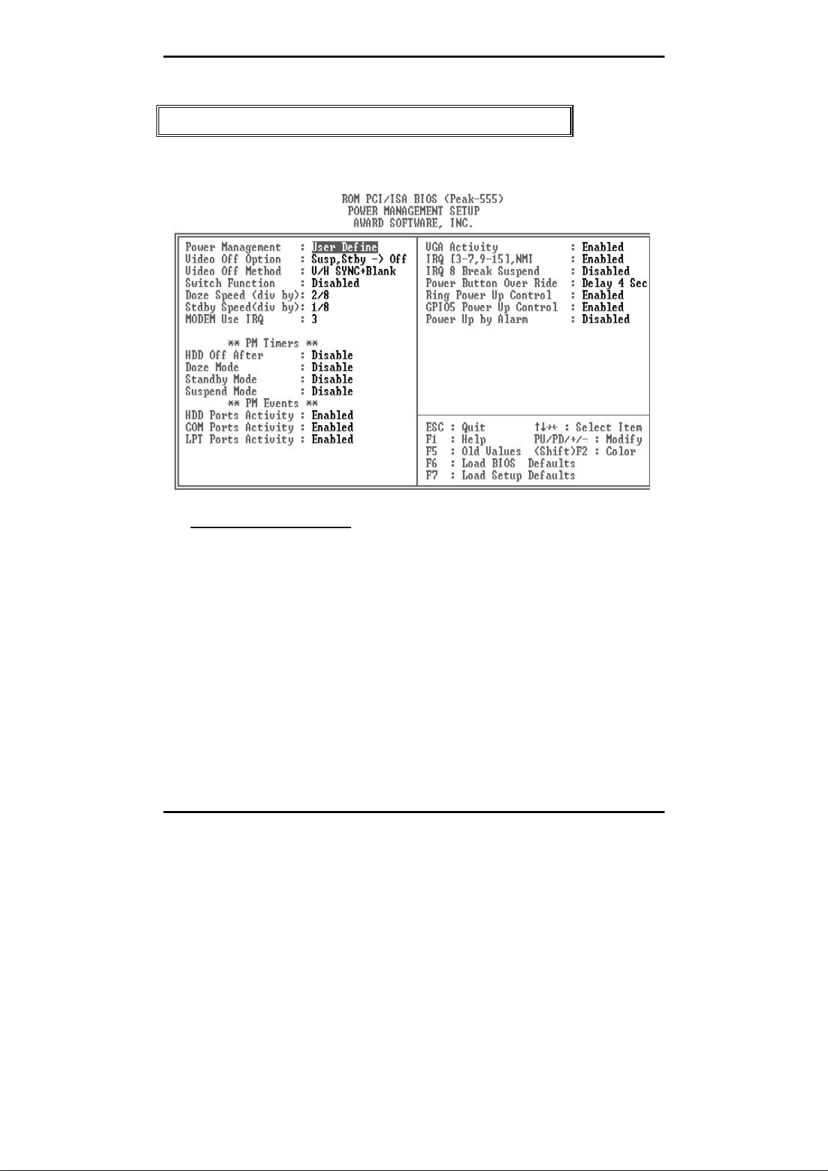
Power Management Setup
The Power management setup will appear on your screen like this:
Power Management
This category determines how much power consumption for system after
selecting below items. Default value is Disable. The following pages tell
you the options of each item & describe the meanings of each options.
BIOS Setup 4-23
Page 54

Peak 555A User’s Guide
to (1), BIOS will also turn off the
A.Power Management 1. Disable Global Power Management will be disabled
2. User Define Users can configure their own power
3. Min Saving Pre-defined timer values are used such that
B. Video Off Option
C. Video Off Method 1. Blank Screen The system BIOS will only blanks off the
2. V/H SYN
3. DPMS
Item Options Descriptions
management
all timers are in their MAX value
4. Max Saving Pre-defined timer values are used such that
1. Always On System BIOS will never turn off the screen
2. Suspend->Off Screen off when system is in SUSPEND
3. Susp, stby->Off Screen off when system is in STANDBY or
4. All Modes ->Off Screen off when system is in DOZE,
C+Blank
Supported
Note: Green monitors
all timers MIN value
mode
SUSPEND mode
STANDBY or SUSPEND mode
screen when disabling video
In addition
V-SYNC & H-SYNC signals from VGA cards
to monitor
This function is enabled for only the VGA
card supporting DPMS
detect the V/H
SYNC signals to
turn off its electron
gun
BIOS Setup 4-24
Page 55

Peak 555A User’s Guide
D. Switch Function
2. Wake The External Suspend Switch is “Wake”
2. 1 Min
E. Doze Speed(div by)
Stdby speed (div by)
F. Modem Use IRQ
G. Standby Mode
(*) Remark 1
2. 10 sec
Note: Normally,STANDBY
BIOS Setup 4-25
1. Break The External Suspend Switch is “Break”
2 Min
4 Min
6 Min
8 Min
10 Min
20 Min
30 Min
40 Min
1 Hr
Note: Normally,STANDBY
1/8
2/8
3/8
4/8
5/8
6/8
7/8
8/8
3,4,5,7,9
4,10,11,NA
1. Disable System will never enter STANDBY mode
1 Min
10 Min
30 Min
1 Hour
2 Hour
20 Min
Defines the continuous idle time before the
system entering DOZE mode.
if any item defined in (J) is enabled & active,
DOZE timer will be reloaded
mode puts the system
into low speed or 8
MHz, screen may be
off depend on (E)
System full speed could be divided by the
optional integers, the bigger the number the
slower the speed under Doze or standby
mode
For external modem, 3 or 4 will be used for
card type modem. It is up to card definition.
Default is 3.
Defines the continuous idle time before the
system entering STANDBY mode.
if any item defined in (J) is enabled & active,
STANDBY timer will be reloaded
mode puts the system
into low speed or 8
MHz, screen may be
off depend on (E)
Page 56

Peak 555A User’s Guide
H. Doze
(*) Remark 1
2. 1 Min
Note: Normally,STANDBY
I. Suspend Mode
(*) Remark 1
2. 1 Min
Note: Normally,SUSPEND
J. HDD Off 1. Disable HDD’s motor will not off
After:
1. Disable System will never enter STANDBY mode
2 Min
4 Min
6 Min
8 Min
10 Min
20 Min
30 Min
40 Min
1 Hr
1. Disable Sy stem will never enter SUSPEND mode
2 Min
4 Min
6 Min
8 Min
10 Min
20 Min
30 Min
40 Min
1 Hr
2.10 Sec
1 Min
10 Min
30 Min
1 Hour
2 Hour
4 Hour
Defines the continuous idle time before the
system entering STANDBY mode.
if any item defined in (J) is enabled & active,
STANDBY timer will be reloaded
mode puts the system
into low speed or 8
MHz, screen may be
off depend on (E)
Defines the continuous idle time before the
system entering SUSPEND mode.
if any item defined in (J) is enabled & active,
SUSPEND timer will be reloaded
mode puts the system
into low speed or 8
MHz, clock is
stopped, screen may
be off depend on (E)
Defines the continuous HDD idle time before
the HDD entering power saving mode (motor
off)
BIOS Setup 4-26
Page 57

Peak 555A User’s Guide
K. VGA Activity
IRQ3 (COM 2)
IRQ4 (COM 1)
IRQ5 (LPT 2)
IRQ6 (Floppy Disk)
IRQ7 (LPT 1)
IRQ8 (RTC Alarm)
IRQ9 (IRQ2 Redir)
IRQ10 (Reserved)
IRQ11 (Reserved)
IRQ12 (PS/2 Mouse)
IRQ13 (Coprocessor)
IRQ14 (Hard Disk)
IRQ15 (Reserved)
L. Power Bottom
Over Ride
* Remark 1: All items mark with (*) in this menu, will be loaded with predefined values
as long as the item ‘Power Management’ is not configured to ‘User
Defined’
These items are:
Item ‘System Doze’ , ‘System Standby’ & ‘System Suspend’
# Remark 2: Although the item ‘HDD Power Down’ is not controlled by item ‘Power
Management’ in terms of timer value, the HDD (s) will not power down if
the global power management is disabled!
1. Disabled
2. Enabled
1. Delay 4 Sec
2. Instant off
BIOS Setup 4-27
Page 58

Peak 555A User’s Guide
PnP/PCI Configuration
This section describes configuring the PCI bus system. PCI, or
Peripheral Component Interconnect, is a system which allows I/O
devices to operate at speeds nearing the speed the CPU itself uses
when communicating with its own special components. This section
covers some very technical items and it is strongly recommended
that only experienced users should make any changes to the default
settings.
ROM PCI/ISA BIOS (Peak-555)
POWER MANAGEMENT SETUP
AWARD SOFTWARE, INC.
Resources Controlled By : Auto PCI IRQ Actived By : Level
Reset Configuration Data : Disabled Onboard PCI SCSI : Enabled
Used MEM base addr : N/A
ESC : Quit ↑ ↓ → ←: Select Item
F1 : Help PU/PD/+/- : Modify
F5 : Old Values (Shift) F2 : Color
F6 : Load BIOS Defaults
F7 : Load Setup Defaults
BIOS Setup 4-28
Page 59

Peak 555A User’s Guide
Resource Controlled by
The Award Plug and Play BIOS has the capacity to automatically
configure all of the boot and Plug and Play compatible devices. However,
this capability means absolutely nothing unless you are using a Plug and
Play operating system such as Windows 95.
Choices are Auto and Manual (default).
Reset Configuration Data
This item allows you to determine reset the configuration data or not.
Choices are Enabled and Disabled (default).
IRQ/DMA Assigned To
This item allows you to determine the IRQ / DMA assigned to the ISA bus
and is not available to any PCI slot. (Legacy ISA) or PnP for both ISA and
PCI.
Choices are Legacy ISA and PCI/ISA PnP.
PCI IRQ Activated by
This sets the method by which the PCI bus recognizes that an IRQ service
is being requested by a device. Under all circumstances, you should
retain the default configuration unless advised otherwise by your
system’s manufacturer.
Choices are Level (default) and Edge.
BIOS Setup 4-29
Page 60

Peak 555A User’s Guide
System Environment
ROM PCI / ISA BIOS (Peak-555)
SYSTEM ENVIRONMENT
AWARD SOFTWARE, INC.
Current CPU Temperature
Current CPU FAN Speed : DRPM
In 0(v) : 5.08V
In 2(v) : 2.80V
System Environment show only
In 0 12V
In 1 5V
In 2 VI/O
In 3 Vcore
ESC : Quit ↑ ↓ → ←: Select Item
F1 : Help PU/PD/+/- : Modify
F5 : Old Values (Shift) F2 : Color
F6 : Load BIOS Defaults
F7 : Load Setup Defaults
BIOS Setup 4-30
Page 61

Peak 555A User’s Guide
Integrated Peripherals
ROM PCI / ISA BIOS (Peak-555)
INTEGRATED PERIPHERALS
AWARD SOFTWARE, INC.
Internal PCI/IDE : Both
IDE Primary Master PIO : Auto
IDE Primary Slave PIO : Auto
IDE Secondary Master
PIO
IDE Secondary Slave PIO : Auto Parallel Port Mode : SPP
Primary Master UltraDMA : Auto
Primary Slave UltraDMA : Auto
Secondary
MasterUltraDMA
Secondary Slave
UltraDMA
IDE Burst Mode : Enabled Init Display First : AGP
IDE Data Port Post Write : Disabled VGA Shared Memory
IDE HDD Block Mode : Enabled VGA Memory Clock : 66
KBC input clock : 8 MHz
Onboard FDC Controller : Enabled
Onboard Serial Port 1 :
Onboard Serial Port 2 :
Onboard IR Controller : Disabled
IDE HDD Block Mode
This allows your hard disk controller to use the fast block mode to transfer
data to and from your hard disk drive (HDD).
Enabled IDE controller uses block mode.
Disabled (Default) IDE controller uses standard
IDE Primary/Secondary Master/Slave PIO
: Auto Onboard Parallel Port :
278/IRQ5
: Auto USB Controller : Disabled
: Auto
: 4 MB
Size
ESC : Quit ↑ ↓ → ←: Select Item
3F8/IRQ4
F1 : Help PU/PD/+/- : Modify
2F8/IRQ3
F5 : Old Values (Shift) F2 : Color
F6 : Load BIOS Defaults
F7 : Load Setup Defaults
mode.
BIOS Setup 4-31
Page 62

Peak 555A User’s Guide
The four IDE PIO (Programmed Input/Output) fields let you set a PIO
mode (0-4) for each of the four IDE devices that the onboard IDE
interface supports. Modes 0 through 4 provide successively increased
performance. In Auto mode, the system automatically determines the
best mode for each device.
IDE Primary/Secondary Master/Slave UDMA
Ultra DMA/33 implementation is possible only if your IDE hard drive
supports it and the operating environment includes a DMA driver
(Windows 95 OSR2 or a third-party IDE bus master driver). If your hard
drive and your system software both support Ultra DMA/33, select Auto to
enable BIOS support. The Choice: Auto (Default), Disabled
On-Chip Primary/Secondary PCI IDE
The integrated peripheral controller contains an IDE interface with
support for two IDE channels. Select Enabled (Default) to activate each
channel separately.
Onboard PCI SCSI Chip
This item allows you to determine whether onboard PCI SCSI chip is
enabled (Default) or not.
USB Keyboard Support
Select Enabled if your system contains a Universal Serial Bus (USB)
controller and you have a USB keyboard. The Choice: Enabled, Disabled
(Default).
Onboard FDC Controller
Select Enabled if your system has a floppy disk controller (FDC) installed
on the system board and you wish to use it. If you install and-in FDC or
the system has no floppy drive, select Disabled in this field. Choices:
Enabled (Default), Disabled.
Onboard Serial Port 1/Port 2
This item allows you to determine access onboard serial port 1/port 2
controller with which I/O address. The Choice: 3F8/IRQ4, 2F8/IRQ3,
3E8/IRQ4, 2F8/IRQ3, Disabled, Auto (Default).
UART 2 Mode
BIOS Setup 4-32
Page 63

Peak 555A User’s Guide
This item allows you to determine which Infra Red (IR) function of
onboard I/O chip. The Choice: Standard (Default), IrDA1.0, ASK-IR,
IrDA1.1
Duplex Select
This item allows you to select the IR function when your select the UART 2
Mode is IrDA1.0, ASK-IR, IrDA1.1
Choices are Half, Full.
TxD, RxD Active
This item allows you to determine the active of RxD, TxD.
Choices are “Hi, Hi”, “Lo, Lo”, “Lo, Hi”, “Hi, Lo”.
Onboard Parallel Port
Select a logical LPT port name and matching address for the physical parallel
(printer) port. The choice: 378H/IRQ7 (Default), 278H/IRQ5, 3BCH/IRQ7,
Disabled.
Parallel Port Mode
Select an operating mode for the onboard parallel port. Select Compatible or
Extended unless you are certain both your hardware and software support
EPP or ECP mode.
The choice: SPP, ECP+EPP1.7, EPP1.7+SPP, EPP1.9+SPP, ECP,
ECP+EPP1.9 (Default), and Normal.
ECP Mode Use DMA
Select a DMA channel for the port.
Choices are 3 (Default), 1.
BIOS Setup 4-33
Page 64

Peak 555A User’s Guide
Supervisor/User Password Setting
You can set either supervisor or user password, or both of then. The differences
between are:
supervisor password : can enter and change the options of the setup menus.
user password : just can enter but do not have the right to change the
options of the setup menus.
When you select this function, the following message will appear at the center of
the screen to assist you in creating a password.
ENTER PASSWORD:
Type the password, up to eight characters in length, and press <Enter>. The
password typed now will clear any previously entered password from CMOS
memory. You will be asked to confirm the password. Type the password again
and press <Enter>. You may also press <Esc> to abort the selection and not
enter a password.
To disable a password, just press <Enter> when you are prompted to enter the
password. A message will confirm the password will be disabled. Once the
password is disabled, the system will boot and you can enter Setup freely.
PASSWORD DISABLED.
When a password has been enabled, you will be prompted to enter it every time
you try to enter Setup. This prevents an unauthorized person from changing any
part of your system configuration.
Additionally, when a password is enabled, you can also require the BIOS to
request a password every time your system is rebooted. This would prevent
unauthorized use of your computer.
You determine when the password is required within the BIOS Features Setup
Menu and its Security option (see Section 4). If the Security option is set to
“System”, the password will be required both at boot and at entry to Setup. If set
to “Setup”, prompting only occurs when trying to enter Setup.
BIOS Setup 4-34
Page 65

Peak 555A User’s Guide
16
16
MP LANDZONE SECTORS MODE
IDE HDD Auto Detection
The Enhance IDE features was included in all Award BIOS. Below is a brief
description of this feature.
1. Setup Changes
<I> Auto-detection
BIOS setup will display all possible modes that supported by the
HDD
including NORMAL, LBA & LARGE.
if HDD does not support LBA modes, no ‘LBA’option will be
shown.
Users can select a mode which is appropriate for them.
HARD DISKS TYPE SIZE CYLS HEAD PRECOMP LANDZ SECTOR MODE
Primary Master :
OPTION SIZE CYLS HEADS PRECO
1(Y) 516 1120 16 65535 1119 59 NORMAL
2 516 524 32 0 1119 63 LBA
3 516 560 32 65535 1119 59 LARGE
<II> Standard CMOS Setup
ROM/PCI/ISA BOPS (2XXXXXXX)
CMOS SETUP UTILITY
AWARD SOFTWARE, INC.
Select Primary Master Option (N = Skip ) : N
CYLS Heads Precomp Landzone Sector Mode
Primary Master: User (516MB) 1120
Primary Slave: None
(203MB)
BIOS Setup 4-35
684
65535
65535
1119 59 Norma
l
685 38 ------
Page 66

Peak 555A User’s Guide
0 0 0 0 0
0 0 0 0 0
Secondary
Master:
Secondary Slave None 0
None 0
When HDD type is in ‘user’ type, the “MODE” option will be opened for user
to select their own HDD mode.
(2) HDD Modes
The Award BIOS supports 3 HDD modes : NORMAL, LBA & LARGE
NORMAL mode
Generic access mode in which neither the BIOS nor the IDE controller will
make any transformations during accessing.
The maximum number of cylinders, head & sectors for NORMAL mode
are 1024, 16 & 63.
no. Cyclinder (1024)
x no. Head ( 16)
x no. Sector ( 63)
x no. per sector ( 512)
528 Megabytes
If user set his HDD to NORMAL mode, the maximum accessible HDD
size will be 528 Megabytes even though its physical size may be greater
than that!
LBA (Logical Block Addressing) mode
A new HDD accessing method to overcome the 528 Megabyte
bottleneck. The number of cylinders, heads & sectors shown in
setup may not be the number physically contained in
the HDD.
During HDD accessing, the IDE controller will transform the logical
address described by sector, head & cylinder number into its own physical
address inside the HDD.
BIOS Setup 4-36
Page 67

Peak 555A User’s Guide
The maximum HDD size supported by LBA mode is 8.4 Gigabytes which is
obtained by
the following formula:
no. Cyclinder ( 1024)
x no. Head ( 255)
x no. Sector ( 63)
x bytes per sector ( 512)
8.4 Gigabytes
LARGE mode
Extended HDD access mode supported by Award Software.
Some IDE HDDs contain more than 1024 cylinder without LBA support (in
some cases, user do not want LBA). The Award BIOS provides another
alternative to support these kinds of HDD!
Example of LARGE mode:
CYLS. HEADS SECTOR MODE
1120 16 59 NORMAL
560 32 59 LARGE
BIOS tricks DOS (or other OS) that the number of cylinders is less than
1024 by
dividing it by 2. At the same time, the number of heads is multiplied by 2.
A reverse transformation process will be made inside INT13h in
order to access the right HDD address the right HDD address!
Maximum HDD size:
no. Cyclinder ( 1024)
x no. Head ( 32)
x no. Sector ( 63)
x bytes per sector ( 512)
1 Gigabytes
BIOS Setup 4-37
Page 68

Peak 555A User’s Guide
(3) Remarks
To support LBA or LARGE mode of HDDs, there must be some softwares
involved. All these softwares are located in the Award HDD Service
Routine(INT 13h). It may be
failed to access a HDD with LBA (LARGE) mode selected if you are
running under a Operating System which replaces the whole INT
13h.
BIOS Setup 4-38
Page 69

Peak 555A User’s Guide
Power-On Boot
After you have made all the changes to CMOS values and the system cannot
boot with the CMOS values selected in Setup, restart the system by turning it
OFF then ON or Pressing the "RESET" button on the system case. You may
also restart by simultaneously press <Ctrl>, <Alt>, and <Delete> keys.
Upon restart the system, immediately press <Insert> to load BIOS default
CMOS value for boot up.
BIOS Setup 4-39
Page 70

Peak 555A User’s Guide
BIOS Reference - POST Message
During the Power On Self Test (POST), if the BIOS detects an error requiring you
to do something to fix, it will either sound a beep code or display a message.
If a message is displayed, it will be accompanied by:
PRESS F1 TO CONTINUE, CTRL-ALT-ESC OR DEL TO ENTER SETUP
POST Beep
Currently there is only one beep code in BIOS. This code indicates that a
video error has occurred and the BIOS cannot initialize the video screen
to display any additional information. This beep code consists of a single
long beep followed by two short beeps.
Error Messages
One or more of the following messages may be displayed if the BIOS
detects an error during the POST. This list includes messages for both
the ISA and the EISA BIOS.
CMOS BATTERY HAS FAILED
CMOS battery is no longer functional. It should be replaced.
CMOS CHECKSUM ERROR
Checksum of CMOS is incorrect. This can indicate that CMOS has
become corrupt. This error may have been caused by a weak battery.
Check the battery and replace if necessary.
BIOS Setup 4-40
Page 71

Peak 555A User’s Guide
DISK BOOT FAILURE, INSERT SYSTEM DISK AND PRESS ENTER
No boot device was found. This could mean that either a boot drive was
not detected or the drive does not contain proper system boot files. Insert
a system disk into Drive A: and press <Enter>. If you assumed the
system would boot from the hard drive, make sure the controller is
inserted correctly and all cables are properly attached. Also be sure the
disk is formatted as a boot device. Then reboot the system.
DISKETTE DRIVES OR TYPES MISMATCH ERROR - RUN SETUP
Type of diskette drive installed in the system is different from the CMOS
definition. Run Setup to reconfigure the drive type correctly.
DISPLAY SWITCH IS SET INCORRECTLY
Display switch on the motherboard can be set to either monochrome or
color. This indicates the switch is set to a different setting than indicated
in Setup. Determine which setting is correct, and then either turn off the
system and change the jumper, or enter Setup and change the VIDEO
selection.
DISPLAY TYPE HAS CHANGED SINCE LAST BOOT
Since last powering off the system, the display adapter has been
changed. You must configure the system for the new display type.
EISA Configuration Checksum Error
PLEASE RUN EISA CONFIGURATION UTILITY
The EISA non-volatile RAM checksum is incorrect or cannot correctly
read the EISA slot. This can indicate either the EISA non-volatile
memory has become corrupt or the slot has been configured incorrectly.
Also be sure the card is installed firmly in the slot.
EISA Configuration Is Not Complete
PLEASE RUN EISA CONFIGURATION UTILITY
The slot configuration information stored in the EISA non-volatile
memory is incomplete.
Note: When either of these errors appear, the system will boot in ISA
mode, which allows you to run the EISA Configuration Utility.
BIOS Setup 4-41
Page 72

Peak 555A User’s Guide
ERROR ENCOUNTERED INITIALIZING HARD DRIVE
Hard drive cannot be initialized. Be sure the adapter is installed correctly
and all cables are correctly and firmly attached. Also be sure the correct
hard drive type is selected in Setup.
ERROR INITIALIZING HARD DISK CONTROLLER
Cannot initialize controller. Make sure the cord is correctly and firmly
installed in the bus. Be sure the correct hard drive type is selected in
Setup. Also check to see if any jumper needs to be set correctly on the
hard drive.
FLOPPY DISK CNTRLR ERROR OR NO CNTRLR PRESENT
Cannot find or initialize the floppy drive controller. make sure the
controller is installed correctly and firmly. If there are no floppy drives
installed, be sure the Diskette Drive selection in Setup is set to NONE.
Invalid EISA Configuration
PLEASE RUN EISA CONFIGURATION UTILITY
The non-volatile memory containing EISA configuration information was
programmed incorrectly or has become corrupt. Re-run EISA
configuration utility to correctly program the memory.
NOTE: When this error appears, the system will boot in ISA mode, which
allows you to run the EISA Configuration Utility.
KEYBOARD ERROR OR NO KEYBOARD PRESENT
Cannot initialize the keyboard. Make sure the keyboard is attached
correctly and no keys are being pressed during the boot.
If you are purposely configurating the system without a keyboard, set the
error halt condition in Setup to HALT ON ALL, BUT KEYBOARD. This
will cause the BIOS to ignore the missing keyboard and continue the boot.
Memory Address Error at ...
Indicates a memory address error at a specific location. You can use this
location along with the memory map for your system to find and replace
the bad memory chips.
BIOS Setup 4-42
Page 73

Peak 555A User’s Guide
Memory parity Error at ...
Indicates a memory parity error at a specific location. You can use this
location along with the memory map for your system to find and replace
the bad memory chips.
MEMORY SIZE HAS CHANGED SINCE LAST BOOT
Memory has been added or removed since the last boot. In EISA mode
use Configuration Utility to reconfigure the memory configuration. In ISA
mode enter Setup and enter the new memory size in the memory fields.
Memory Verify Error at ...
Indicates an error verifying a value already written to memory. Use the
location along with your system's memory map to locate the bad chip.
OFFENDING ADDRESS NOT FOUND
This message is used in conjunction with the I/O CHANNEL CHECK and
RAM PARITY ERROR messages when the segment that has caused the
problem cannot be isolated.
OFFENDING SEGMENT:
This message is used in conjunction with the I/O CHANNEL CHECK and
RAM PARITY ERROR messages when the segment that has caused the
problem has been isolated.
PRESS A KEY TO REBOOT
This will be displayed at the bottom screen when an error occurs that
requires you to reboot. Press any key and the system will reboot.
PRESS F1 TO DISABLE NMI, F2 TO REBOOT
When BIOS detects a Non-maskable Interrupt condition during boot, this
will allow you to disable the NMI and continue to boot, or you can reboot
the system with the NMI enabled.
BIOS Setup 4-43
Page 74

Peak 555A User’s Guide
RAM PARITY ERROR - CHECKING FOR SEGMENT ...
Indicates a parity error in Random Access Memory.
Should Be Empty But EISA Board Found
PLEASE RUN EISA CONFIGURATION UTILITY
A valid board ID was found in a slot that was configurated as having no
board ID.
NOTE; When this error appears, the system will boot in ISA mode, which
allows you to run the EISA Configuration Utility.
Should Have EISA Board But Not Found
PLEASE RUN EISA CONFIGURATION UTILITY
The board installed is not responding to the ID request, or no board ID has
been found in the indicated slot.
NOTE: When this error appears, the system will boot in ISA mode,
which allows you to run the EISA Configuration Utility.
Slot Not Empty
Indicates that a slot designated as empty by the EISA Configuration Utility
actually contains a board.
NOTE: When this error appears, the system will boot in ISA mode, which
allows you to run the EISA Configuration Utility.
SYSTEM HALTED, (CTRL-ALT-DEL) TO REBOOT ...
Indicates the present boot attempt has been aborted and the system must
be rebooted. Press and hold down the CTRL and ALT keys and press
DEL.
Wrong Board In Slot
PLEASE RUN EISA CONFIGURATION UTILITY
The board ID does not match the ID stored in the EISA non-volatile
memory.
BIOS Setup 4-44
Page 75

Peak 555A User’s Guide
NOTE: When this error appears, the system will
boot in ISA mode, which allows
you to run the EISA Configuration Utility.
BIOS Reference - POST Codes
Note: EISA POST codes are typically output to port address 300h.
ISA POST codes are output to port address 80h.
POST
(hex)
C0 1. Turn off OEM specific cache, shadow...
C1 Auto-detection of onboard DRAM & Cache
C3 1. Test system BIOS checksum
C5 Copy the BIOS from ROM into E0000-FFFFF shadow RAM so
01-02 Reserved
03 Initialize EISA registers (EISA BIOS only)
04 Reserved
05 1. Keyboard Controller Self-Test
06 Reserved
07 Verifies CMOS’s basic R/W functionality
BE Program defaults values into chipset according to the
09 1. Program the configuration register of Cyrix CPU according
0A 1. Initialize the first 32 interrupt vectors with corresponding
Description
2. Initialize all the standard devices with default values
standard devices
includes:
-DMA controller (8237)
-Programmable Interrupt Controller (8259)
-Programmable Interval Timer (8254)
-RTC chip
2. Test the first 256K DRAM
3. Expand the compressed codes into temporary DRAM area
including the
compressed System BIOS & Option ROMs
that POST will go faster
2. Enable Keyboard Interface
MODBINable Chipset
Default Table
to the
MODBINable Cyrix Register Table
2. OEM specific cache initialization (if needed)
Interrupt handlers
Initialize INT no from 33-120 with Dummy(Suprious)
Interrupt Handler
2. Issue CPUID instruction to identify CPU type
3. Early Power Management initialization (OEM specific)
BIOS Setup 4-45
Page 76

Peak 555A User’s Guide
a This POST code is for boot block
POST
Description
(hex)
C0 1. Turn off OEM specific cache, shadow...
2. Initialize all the standard devices with default values
standard devices
includes:
-DMA controller (8237)
-Programmable Interrupt Controller (8259)
-Programmable Interval Timer (8254)
-RTC chip
C1 Auto-detection of onboard DRAM & Cache
C3 Checking checksum of compressed code
C5 Copy the BIOS from ROM into E0000-FFFFF shadow RAM
so that POST will go faster
01 Clear base memory 0~640K
0C Initial interrupt vector 00-1FH
0D Initial ISA VGA
41H Enable FDD and detect media type
FFH Boot from FDD
BIOS Setup 4-46
Page 77

Peak 555A User’s Guide
a This page is for Non-Compressed Version only
01-0
2
C0 Turn off OEM specific cache, shadow...
03 1. Initialize EISA registers (EISA BIOS only)
04 Reserved
05 1. Keyboard Controller Self-Test
06 Reserved
07 Verifies CMOS’s basic R/W functionality
BE Program defaults values into chipset according to the
C1 Auto-detection of onboard DRAM & Cache
C5 Copy the BIOS from ROM into E0000-FFFFF shadow RAM
08 Test the first 256K DRAM
09 1. Program the configuration register of Cyrix CPU
0A 1. Initialize the first 32 inter rupt vectors with corresponding
Reserved
2. Initialize all the standard devices with default values
Standard devices includes:
-DMA controller (8237)
-Programmable Interrupt Controller (8259)
-Programmable Interval Timer (8254)
-RTC chip
2. Enable Keyboard Interface
MODBINable Chipset
Default Table
so that POST will go faster
according to the
MODBINable Cyrix Register Table
2. OEM specific cache initialization (if needed)
Interrupt
handlers Initialize INT no from 33-120 with
Dummy(Suprious)
Interrupt Handler
2. Issue CPUID instruction to identify CPU type
3. Early Power Management initialization (OEM specific)
BIOS Setup 4-47
Page 78

Peak 555A User’s Guide
a The following POST Codes are for all of Compress Version &
Non-Compress Version
POST
(hex)
0B 1. Verify the RTC time is valid or not
0C
0D 1. Program some of the Chipset’s value according to
0E 1. Initialize the APIC (Multi-Processor BIOS only)
0F DMA channel 0 test
10 DMA channel 1 test
11 DMA page registers test
12-13 Reserved
14 Test 8254 Timer 0 Counter 2.
15 Test 8259 interrupt mask bits for channel 1
16 Test 8259 interrupt mask bits for channel 2
17 Reserved
19 Test 8259 functionality
1A-1D Reserved
1E If EISA NVM checksum is good, execute EISA initialization
1F-29 Reserved
30 Detect Base Memory & Extended Memory Size
Description
2. Detect bad battery
3. Read CMOS data into BIOS stack area
4. PnP initializations including (PnP BIOS only)
-Assign CSN to PnP ISA card
-Create resource map from ESCD
5. Assign IO & Memory for PCI devices (PCI BIOS only)
Initialization of the BIOS Data Area (40 : 00 − 40:FF)
Setup. (Early Setup
Value Program)
2. Measure CPU speed for display & decide the system
clock speed
3. Video initialization including Monochrome, CGA,
EGA/VGA. If no
display device found, the speaker will beep which
consists of one single
long beep followed by two short beeps.
2. Test video RAM (If Monochrome display device found)
3. Show messages including:
-Award Logo, Copyright string, BIOS Date code & Part
No.
-OEM specific sign on messages
-Energy Star Logo (Green BIOS ONLY)
-CPU brand, type & speed
-Test system BIOS checksum(Non-Compress
Version only)
(EISA BIOS only)
BIOS Setup 4-48
Page 79

Peak 555A User’s Guide
31 1. Test Base Memory from 256K to 640K
2. Test Extended Memory from 1M to the top of memory
BIOS Setup 4-49
Page 80

Peak 555A User’s Guide
32 1. Display the Award Plug & Play BIOS Extension message
33-3B Reserved
3C Set flag to allow users to enter CMOS Setup Utility
3D 1. Initialize Keyboard
(PnP BIOS
only)
2. Program all onboard super I/O chips (if any) including
COM ports, LPT
ports, FDD port... according to setup value
2. Install PS2 mouse
BIOS Setup 4-50
Page 81

Peak 555A User’s Guide
POST(hex)
3E Try to turn on Level 2 cache
3E Try to turn on Level 2 cache
BF 1. Program the rest of the Chipset’s value according to
41 Initialize floppy disk drive controller
42 Initialize Hard drive controller
43 If it is a PnP BIOS, initialize serial & parallel ports
44 Reserved
45 Initialize math coprocessor.
46-4D Reserved
4E If there is any error detected (such as video, kb...), show all
4F 1. If password is needed, ask for password
50 Write all CMOS values currently in the BIOS stack area
51 Reserved
52 1. Initialize all ISA ROMs
53 1. If it is NOT a PnP BIOS, initialize serial & parallel ports
60 Setup Virus Protection (Boot Sector Protection)
Description
Note: Some chipset may need to turn on the L2 cache in
this stage. But usually, the cache is turn on later in POST
61h
Note: Some chipset may need to turn on the L2 cache in
this stage. But usually, the cache is turn on later in POST
61h
Setup. (Later Setup
Value Program)
2. If auto-configuration is enabled, programmed the
chipset with pre defined values in the MODBINable Auto-Table
the error messages on the screen & wait for user to press
<F1> key
2. Clear the Energy Star Logo (Green BIOS only)
back into the CMOS
2. Later PCI initializations (PCI BIOS only)
-assign IRQ to PCI devices
-initialize all PCI ROMs
3. PnP Initializations (PnP BIOS only)
-assign IO, Memory, IRQ & DMA to PnP ISA devices
-initialize all PnP ISA ROMs
4. Program shadows RAM according to Setup settings
5. Program parity according to Setup setting
6. Power Management Initialization
-Enable/Disable global PM
-APM interface initialization
2. Initialize time value in BIOS data area by translate the
RTC time value
into a timer tick value
functionality according to Setup settin
BIOS Setup 4-51
Page 82

Peak 555A User’s Guide
BIOS Default Drive Table
This is a current list of the drive type table contained in Setup.
Type Size
(MB)
1 10 306 4 17 128 305 TEAC
2 20 615 4 17 300 615 Seagate
3 30 615 6 17 300 615
4 62 940 8 17 512 940
5 46 940 6 17 512 940
6 20 615 4 17 None 615 Seagate
7 30 462 8 17 256 511
8 30 733 5 17 None 733 Tandon TM
9 112 900 15 17 None 901
10 20 820 3 17 None 820
11 35 855 5 17 None 855
12 49 855 7 17 None 855
13 20 306 8 17 128 319 Disctron
14 42 733 7 17 None 733
15 Reserved
16 20 612 4 17 0 663 Microscien
17 40 977 5 17 300 977
18 56 977 7 17 None 977
19 59 1024 7 17 512 1023
Cylinders Heads Sectors Write
Precomp
Land
Zone
Example
Model
SD510,
MMI 112,
5412
ST225,
ST4026
ST125,
Tandon
TM262
703
526, MMI
M125
ce HH725,
Syquest
3250, 3425
BIOS Setup 4-52
Page 83

Peak 555A User’s Guide
20 30 733 5 17 300 732
21 42 733 7 17 300 732
22 30 306 5 17 300 733 Seagate
23 10 977 4 17 0 336
ST4038
BIOS Setup 4-53
Page 84

Peak 555A User’s Guide
24 40 1024 5 17 None 976 Seagate
ST4051
25 76 1224 9 17 None 1023 Seagate
ST4096
26 71 1224 7 17 None 1223 Maxtor
2085
27 111 1224 11 17 None 1223 Maxtor
2140,
Priam S14
28 152 1024 15 17 None 1223 Maxtor
2190,
Priam S19
29 68 1024 8 17 None 1023 Maxtor
1085,
Micropolis
1325
30 93 918 11 17 None 1023 Maxtor
1105 1120,
4780
31 83 925 11 17 None 1023 Maxtor
1170
32 69 1024 9 17 None 926 CDC 9415
33 85 1024 10 17 None 1023
34 102 1024 12 17 None 1023
35 110 1024 13 17 None 1023
36 119 1024 14 17 None 1023
37 17 1024 2 17 None 1023
38 136 1024 16 17 None 1023
39 114 918 15 17 None 1023 Maxtor
1140, 4380
40 40 820 6 17 None 820 Seagate
ST251
41 42 1024 5 17 None 1023 Seagate
4053
Miniscribe
3053/6053
42 65 1024 5 26 None 1023 Miniscribe
3053/6053
RLL
43 40 809 6 17 None 852 Miniscribe
3650
44 61 809 6 26 None 852 Miniscribe
3675 RLL
45 100 776 8 33 None 775 Conner
CP3104
46 203 684 16 38 None 685 Conner
CP3204
BIOS Setup 4-54
Page 85

Peak 555A User’s Guide
User
BIOS Setup 4-55
Page 86

Peak 555A User’s Guide
Appendix
Watch Dog Timer
Set up menu: refer to Page 4-24, “Integrated Peripherals”
WDT Configuration port F2 Default at F2
Watch Dog Timer Disabled 1. Default at disabled
Enabled
WDT Time out active for Reset Default at Reset
NMI
WDT Active Time 1 sec
2 sec
4 sec
8 sec
16 sec
32 sec
64 sec
2. Enabled for user′s programming
Default at 64sec
You can program “INDEX 7D” in the CMOS RAM to read or change the set up
information.
Example • Read index 7D in the CMOS RAM
MOV DX, 70
MOV AL, 7D
OUT DX, AL
MOV DX, 71
IN AL, DX
• Write to index 7D in the CMOS RAM
MOV DX, 70
MOV AL, 7D
OUT DX, AL
MOV DX, 71
MOV AL, Data
OUT DX, AL
Watch Dog Timer A-1
Page 87

Peak 555A User’s Guide
Port Used
Default at F2
Bit definitions of F2
D4: 1 select NMI
0 select Reset
D3: 1 Enable watch dog timer
0 Disable watch dog timer
< D2, D1, D0>: 111 : N/A
110 : Select 1 second
101 : Select 2 second
100 : Select 4 second
011 : Select 8 second
010 : Select 16 second
001 : Select 32 second
000 : Select 64 second
Watch dog Timer Programming Procedure
• Power on or reset the system
The values of D4~D0 in port F2 are zero, i.e. the watch dog timer is disabled
• Clear the WDT, repeatedly read port F2 with the duration no longer than the
preset
time out interval, otherwise, the WDT will generate NMI or reset the system.
Watch Dog Timer A-2
Page 88

Peak 555A User’s Guide
• Initialize the SQW of RTC, set SQW output period=0.5 second
Out port 70 = 0A
Out port 71 = 2F ( generate SQW = 0.5 Sec.)
Out port 70 = 0B
Out port 71 = 0A ( enable the SQW output)
• Select the time out intervals of WDT (decide the values of D2, D1, D0 in F2 ,
if you reset the system, i.e. D2~D0 = 0, the time out interval will be 64 sec.)
• Select NMI or CPU reset (decide D4 value in F2 or F6, if you just reset the
system, i.e. D4 = 0, then it’s CPU reset)
• Enable or disable WDT ( decide D3 value in F2, if you reset the
system, i.e. D3=0, it’s “disable”)
• You should build in a mechanism in the program to always read F2 to clear
WDT before the time out of WDT.
Watch Dog Timer A-3
Page 89

Peak 555A User’s Guide
An Example
a. Enable watchdog timer
b. Select I/O port F2 & set WDT timer at 1 sec interval
c. Select NMI
d. Enable WDT
e. Clear WDT
f. Disable WDT
a. Set RTC to generate WDT timer source “SQW” to generate 0.5 sec.
duty cycle timer source
MOV AL, 0A ; Set RTC output signal “SQW” to generate 0.5 sec.
cycling timer
MOV DX, 070
OUT DX, AL
MOV AL, 2F
MOV DX, 071
OUT DX, AL
MOV AL, 0B ; Enable “SQW” signal pin active
MOV DX, 070
OUT DX, AL
MOV AL, 0A
MOV DX, 071
OUT DX, AL
Watch Dog Timer A-4
Page 90

Peak 555A User’s Guide
b. Select WDT timer setting (use port F2)
MOV AL, 06 ; Setting WDT=1 sec.
MOV DX, 0F2
OUT DX, AL
c. Select WDT for NMI or reset (select NMI)
MOV DX, 70
MOV AL, 7D
OUT DX, AL
MOV DX, 71
IN AL, DX
OR AL, 10
MOV DX, 0F2
OUT DX, AL
MOV BL, AL
MOV DX, 70
MOV AL, 7D
OUT DX, AL
MOV DX, 71
MOV AL, BL
OUT DX, AL
d. Enable WDT
MOV DX, 70
MOV AL, 7D
OUT DX, AL
MOV DX, 71
IN AL, DX
OR AL, 08
MOV DX, 0F2
OUT DX, AL
MOV BL, AL
MOV DX, 70
MOV AL, 7D
OUT DX, AL
MOV DX, 71
MOV AL, BL
OUT DX, AL
Watch Dog Timer A-5
Page 91

Peak 555A User’s Guide
e. Clear WDT (this operation should be repeatedly executed before
WDT time out, e.g. if WDT time out set at 16 sec., then to clear WDT,
the instruction should be executed within 16 sec. repeatedly)
MOV DX, 0F2
IN AL, DX
f. Disable WDT
MOV DX, 70
MOV AL, 7D
OUT DX, AL
MOV DX, 71
IN AL, DX
AND AL, 0F7
OUT DX, AL
MOV BL, AL
MOV DX, 70
MOV AL, 7D
OUT DX, AL
MOV DX, 71
MOV AL, BL
OUT DX, AL
You can also combine programming procedure b+c+d with same subroutine, for
example, set WDT=1 sec, select NMI and go to enable WDT. The instruction as
followings.
MOV AL, 01E ; Directly write to port F2 to set WDT=1 sec, select
NMI and Enable WDT
MOV DX, 0F2
OUT DX, AL
MOV DX, 70 ; Save to CMOS index 7D
MOV AL, 7D
OUT DX, AL
MOV AL, 01E
MOV DX, 71
OUT DX, AL
Watch Dog Timer A-6
 Loading...