

Page 1

NEXCOM International Co., Ltd.
Multi-Media Solutions
PowerDigis V2 Player
User Manual
NEXCOM International Co., Ltd.
Published August 2012
www.nexcom.comwww.nexcom.com
Page 2
Contents
Contents
Chapter 1: Introduction �������������������������������������������������������������1
1.1 Manual Objective .............................................................................1
1.2 Architecture .....................................................................................2
1.2.1 PowerDigiS Player .......................................................................... 3
1.2.2 Web-based Presentation Designer .................................................3
CHAPTER 2: Player system installation and configuration ����4
2.1 Player Cable Connection ..................................................................4
2.1.1 Managing Player from a separate ................................................. 4
management PC/ laptop ................................................................ 4
2.1.2 Managing Player directly................................................................ 5
2.2 Player Management Console Login ..................................................6
Chapter 3: Player web management console �������������������������7
3.1 Player Status ....................................................................................7
3.2 Player Setting ...................................................................................9
3.2.1 Configure Network Setting ............................................................ 9
3.2.2 Configure Time Setting ............................................................... 10
3.2.3 Configure Display Setting ............................................................ 11
3.3 Creating a Presentation ..................................................................12
3.3.1 Designer Wizard .......................................................................... 12
3.3.2 Manage Content ........................................................................ 13
Add Labels ...................................................................................................... 16
3.3.3 Creating/ Editing a New/ Existing
Presentation ............................................................................... 18
3.3.4 Scene Editor ................................................................................ 20
3.3.5 Content Design .......................................................................... 22
3.4 Scheduling a Presentation ..............................................................23
3.4.1 Export/Import a Schedule File ...................................................... 24
Chapter 4: Player Web Management Console ����������������������25
4.1 Access Control List .........................................................................25
4.2 TV Channel Setting ........................................................................26
4.3 Firmware Update ............................................................................26
4.4. Miscellaneous ...............................................................................27
4.5 Import/Export Player Profile Settings ...............................................29
4.6 Player Control ................................................................................30
4.6.1 Performing Player Actions ............................................................ 30
4.6.2 Configuring RS232 Command ..................................................... 31
4.7 Player Message ..............................................................................32
4.7.1 Composing Emergency Message ................................................. 32
4.7.2 Composing Notification Message ................................................ 33
4.8 Player Alert ....................................................................................34
4.8.1 Configuring Alert Notification Event ........................................... 34
Settings ....................................................................................... 34
4.8.2 Configuring Alert Email Notification
Settings ....................................................................................... 35
4.8.3 Enabling Alert Email Settings ....................................................... 36
Copyright © 2012 NEXCOM International Co., Ltd. All Rights Reserved.
ii
PowerDigis V2 Player User Manual
Page 3
Contents
4.9 Player Log ......................................................................................37
4.9.1 Application/ System Log .............................................................. 37
4.9.2 Proof of Play ................................................................................ 38
4.9.3 Enabling Log Email Alert Setting .................................................. 39
Chapter 5: Interactive Presentation Design & License
Upgrade ������������������������������������������������������������������������������������40
5.1 Interactive Presentation Design .......................................................40
5.1.1 Interactive Presentation Design .................................................... 40
5.1.2 Scene Editor ................................................................................ 41
5.1.3 Content Design ........................................................................... 43
5.1.4 Event Trigger Tree List .................................................................. 45
Create Touch Events ........................................................................................ 45
Create GPS Events ........................................................................................... 49
5.2 License Upgrade .............................................................................51
5.2.1 Online License Upgrade ............................................................... 51
5.2.2 Offline License Upgrade............................................................... 52
Copyright © 2012 NEXCOM International Co., Ltd. All Rights Reserved.
iii
PowerDigis V2 Player User Manual
Page 4
Chapter 1: Product Introduction
Chapter 1: Introduction
1.1 Manual Objective
The objective of this User Manual is to provide a comprehensive
understanding of the PowerDigiS Digital Signage Player. Specifically,
user will be able to reference this manual for assistance with the
following:
•PowerDigiS Player overview
•Detailed descriptions of PowerDigiS Player features and UI functions
•Step-by-Step PowerDigiS Player system installation and configuration
•procedures
•Basic and advanced settings for PowerDigiS Digital Signage Player
•configuration
Copyright © 2012 NEXCOM International Co., Ltd. All Rights Reserved.
1
PowerDigis V2 Player User Manual
Page 5
Chapter 1: Product Introduction
1.2 Architecture
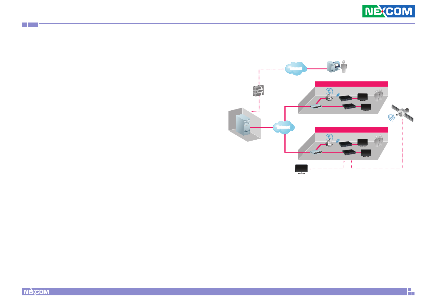
The PowerDigiS Digital Signage Player is a range of network based
digital signage appliances designed to address a broad spectrum
of digital signage applications. It integrates hardware and software
technology seamlessly in digital signage application to provide high
performance media player system and feature rich software solution
tailored to handle high quality play of a great variety of multi-media
contents on single or multiple display devices.
A comprehensive suite of presentation design, media player,
presentation scheduler and web management tools are included with
PowerDigiS solution package which makes for simplified deployment,
management and operation of digital signage applications.
The PowerDigiS Digital Signage Player is composed of the following
major components:
CMS
Server
Back-end Equipment
Firewall
InternetInternet
InternetInternet
Train Station / Airport
LAN
ADSL/ Cable Modem
Shopping Mall / Hospital
LAN
ADSL/ Cable Modem
CATV Network
Wireless AP
Wireless AP
Web User
Remote Access Control for
Scheduling and Content Changing
PDS Player
PDS Player
Passers
Passers
Digital TV
Satellite
Copyright © 2012 NEXCOM International Co., Ltd. All Rights Reserved.
2
PowerDigis V2 Player User Manual
Page 6
Chapter 1: Product Introduction
1.2.1 PowerDigiS Player
The PowerDigiS Player is pre-installed with all required software for
digital signage application to display multi-media presentations on
single or multiple display devices in accordance with user preferable
time and sequence. By using LAN/WAN, multi-media presentations
can be easily saved and scheduled for the PowerDigiS Player remotely
through wired or wireless network.
•Playback ability of most of standard multimedia file types
•Player start/stop/pause/reboot/shutdown control
•Display resolution setting support
•Daily/Weekly/Monthly/Annual presentation scheduling support
•Screen rotation function (landscape/portrait) support
•Output to multiple display devices, independent, clone or combined
•Picture/video wall feature support
•Live TV program playback support
•Instant Emergency/Notification message display support
1.2.2 Web-based Presentation Designer
The PowerDigiS Web-based Designer allows users to design the
presentation via Player or CMS Management Console for a single or
multiple Players. This handy tool gives users the freedom and flexibility
to add, modify and control different types of rich media files, from
simple text messages to advanced combinations of ticker with dynamic
animations, pictures, video files, TV channels or flash movies to
presentation.
•Easy drag and drop content (play item) from content list to specific
zones
•Support unlimited scenes and up to 9 zones in each scene
•Support both Default Layout Templates and User Defined Templates
•Images animation effect in each independent zone
•Web-based UI for intuitive, central management and easy operation
•Import/Export Presentations for more flexibility with Presentation
design in different Players
Copyright © 2012 NEXCOM International Co., Ltd. All Rights Reserved.
3
PowerDigis V2 Player User Manual
Page 7
Chapter 2: Player system installation and configuration
CHAPTER 2: Player system installation and configuration
2.1 Player Cable Connection
You can use either of the following measures to configure the Player
cable connection:
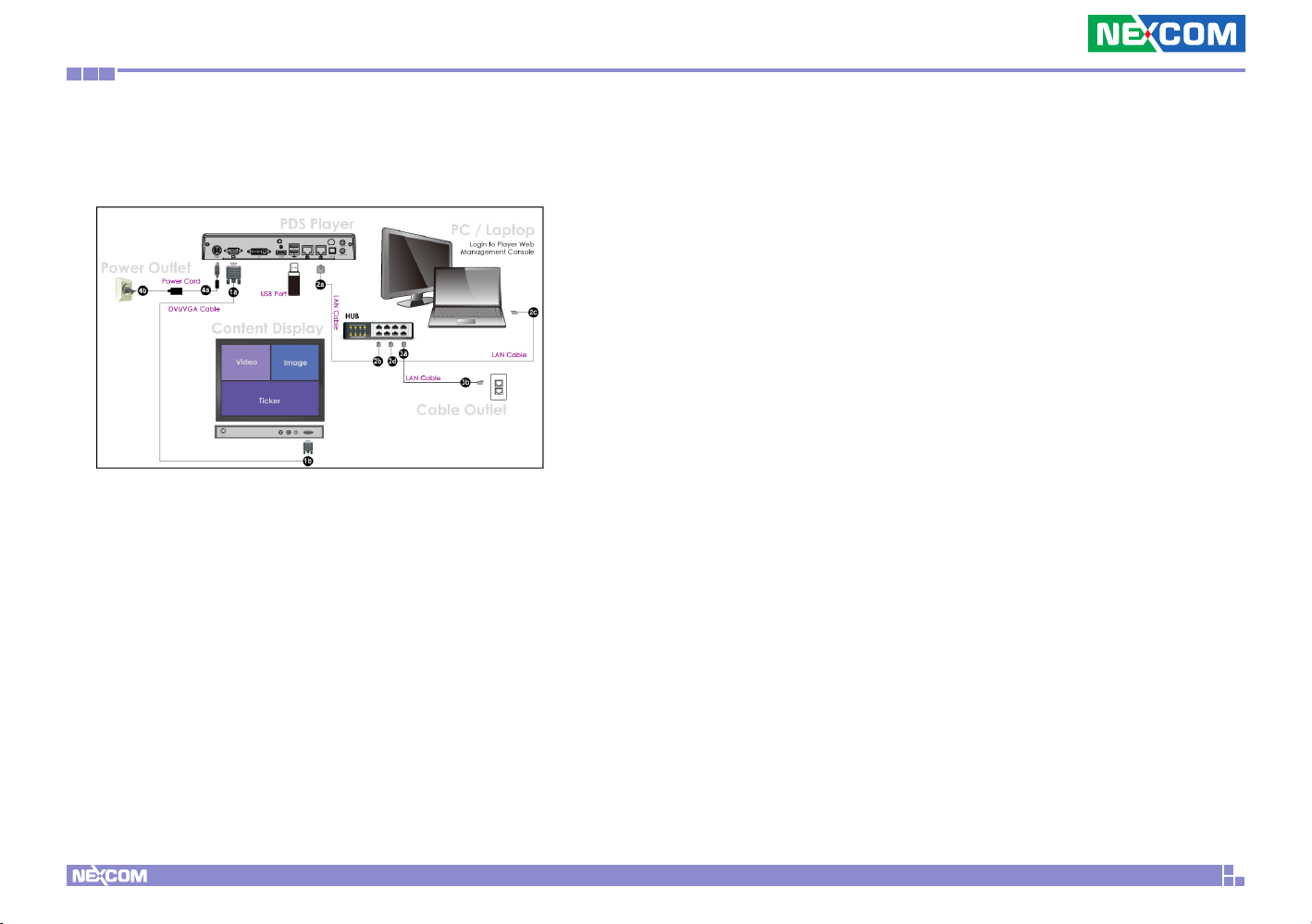
2.1.1 Managing Player from a separate
management PC/ laptop
Step 1a Choose the video output (DVI/VGA/HDMI/LVDS) you would like
to use to connect the cable.
Step 1b Connect another end of the cable to your display.
Step 2a Plug a LAN cable into PDS Player LAN port 1.
Step 2b Connect another end of LAN cable to LAN port 1 on the hub.
Step 2c Plug another LAN cable into Management PC/laptop LAN port
Step 2d Connect another end of LAN cable to LAN port 2 on the hub.
Step 3a Plug the third LAN cable to LAN port 3 on the hub
Step 3b Connect another end of LAN cable to the Cable Outlet
Step 4 Plug the DC end of the power adapter into the power connector
of the PDS
Player unit. Then, plug the AC end to an electrical outlet. Push the
Power button and the PDS Player will power up immediately.
Copyright © 2012 NEXCOM International Co., Ltd. All Rights Reserved.
4
PowerDigis V2 Player User Manual
Page 8
Chapter 2: Player system installation and configuration
2.1.2 Managing Player directly
Step 1a Choose the video output (DVI/VGA/HDMI/LVDS) you would like
to use to connect the cable.
Step 5 Plug the DC end of the power adapter into the power connector
of the PDS Player unit. Then, plug the AC end to an electrical
outlet. Push the Power button and the PDS Player will power up
immediately.
Step 1b Connect another end of the cable to your display.
Step 2a Plug a LAN cable into PDS Player LAN port 1.
Step 2b Connect another end of LAN cable to Cable Outlet
Step 3 Plug the mouse cable into USB pen drive 1 on PDS Player
Step 4 Plug the keyboard cable into USB pen drive 2 on PDS Player
Copyright © 2012 NEXCOM International Co., Ltd. All Rights Reserved.
5
PowerDigis V2 Player User Manual
Page 9
Chapter 2: Player system installation and configuration
2.2 Player Management Console Login
The Player Web Management Console is an user interface which
enables user to remotely control and administrate PDS Player, including
designing and scheduling the presentation, managing Player’s
configuration as well as monitoring Player system information.
•Provide overall system information
•Support Service Restart, System Reboot and Firmware Update features
•Monitor and control major system services
•Manually select default TV channel for Player
•Schedule presentations to be played at specific time as predefined
•View and download Proof of Play message file.
If you log into Player Management Console from a PC/laptop, launch
the browser and type in DHCP IP address appearing on the display
attached to the Player to access the console.
If you log into Player Management Console directly from the Player,
type “password” first to switch the default background image to the
desktop, launch the browser and type in http://localhost to access the
console.
Use the following combo to log into Player Management Console:
Select the language you would like to use. Currently English and
Traditional
Chinese are available.
Username: administrator
Password: welcome
Copyright © 2012 NEXCOM International Co., Ltd. All Rights Reserved.
6
PowerDigis V2 Player User Manual
Page 10
Chapter 3: Player web management console
Chapter 3: Player web management console
3.1 Player Status
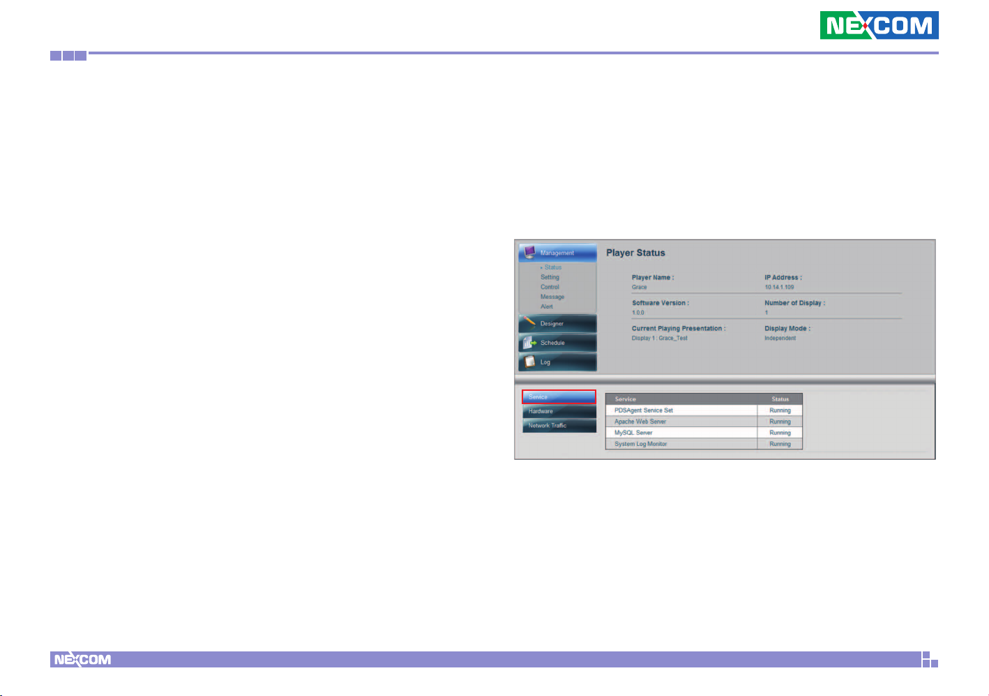
After you log into the Player Console, the first page you see is Player
Status. From this page, you can view Player information, including
Player Name, IP Address, Software Version, Number of Display, Current
Playing Presentation and Display Mode.
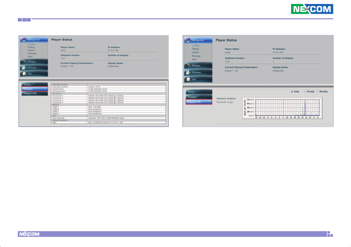
You can also view Player Service, Hardware and Network Traffic info on
the bottom of the same page.
Service info provides Player main services status, including PDSAgent
Service Set, Apache Server, MySQL Server and System Log Monitor.
Copyright © 2012 NEXCOM International Co., Ltd. All Rights Reserved.
Hardware info provides Player hardware configuration details.
7
PowerDigis V2 Player User Manual
Page 11
Chapter 3: Player web management console
Network Traffic provide daily/weekly/monthly Player network bandwidth
usage info.
Copyright © 2012 NEXCOM International Co., Ltd. All Rights Reserved.
8
PowerDigis V2 Player User Manual
Page 12
Chapter 3: Player web management console
3.2 Player Setting
Player Setting allows user to configure different types of settings for
the Player, including Network, Time, Display, ACL and TV Channel,
Firmware Update, Miscellaneous and Profile settings.
Next we are going to introduce the basic settings you need to configure
for Player before you proceed with your presentation design. Please
refer to Chapter 4 “Advanced Settings for Player” for more advanced
settings steps for Player.
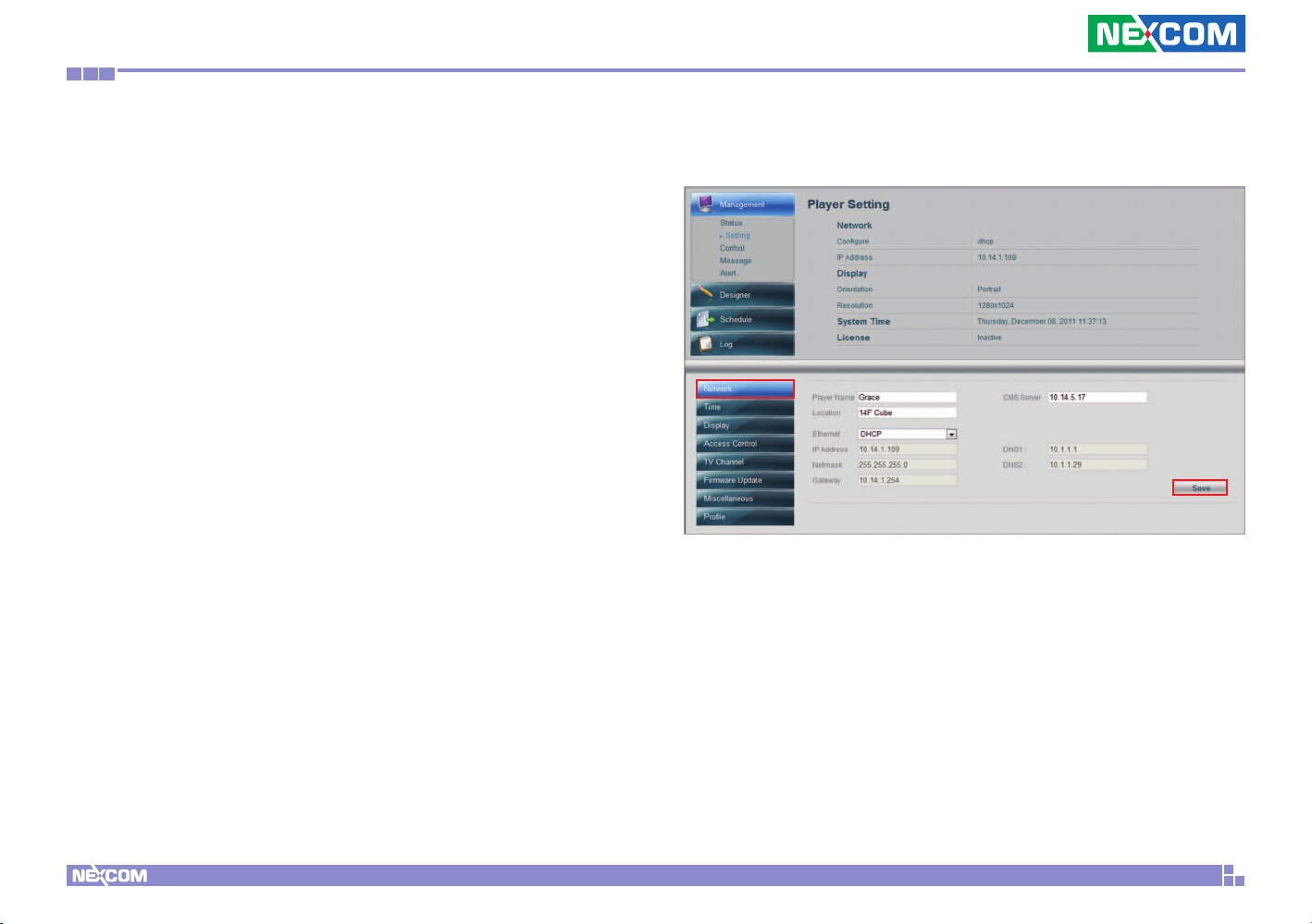
3.2.1 Configure Network Setting
•
Click “Network” from the lower left panel
•Enter Player name and location info
•Select Ethernet type: dhcp or static
•If you have selected static IP, manually enter DNS server IP
•Enter CMS server IP if you want to register Player to a specific CMS
server
•Click Save
Copyright © 2012 NEXCOM International Co., Ltd. All Rights Reserved.
9
PowerDigis V2 Player User Manual
Page 13
Chapter 3: Player web management console
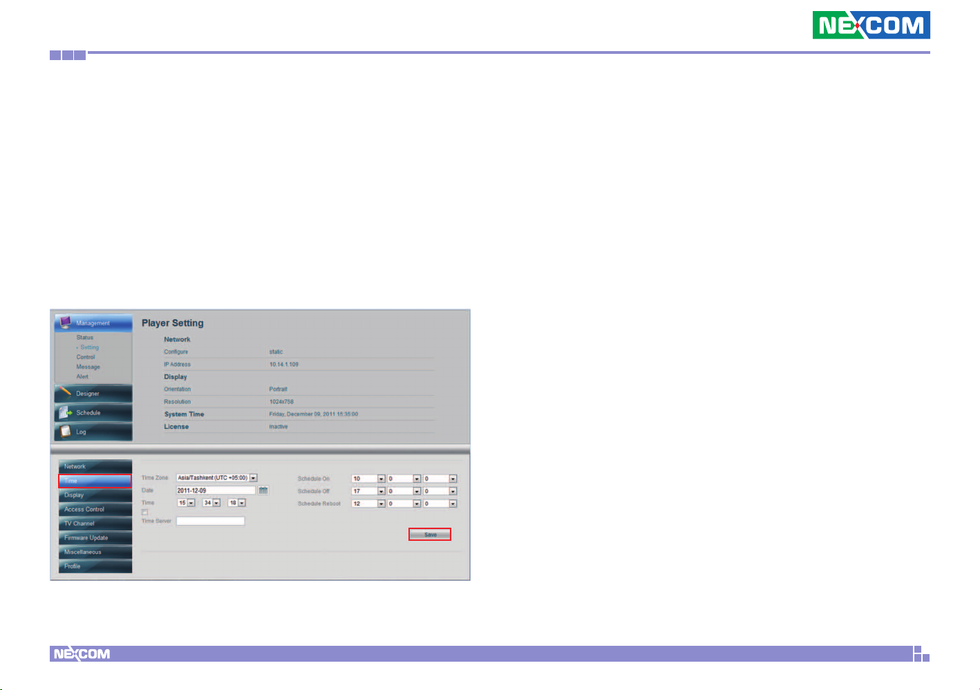
3.2.2 Configure Time Setting
•
Click “Time” from the lower left panel
•Select Time Zone from the dropdown menu
•Select Date and Time from the calendar
•Check Time Server checkbox and enter time server info of to
configure a time server
•You can also set up daily time to automatically power on/off and
reboot Player
•Click Save
Copyright © 2012 NEXCOM International Co., Ltd. All Rights Reserved.
10
PowerDigis V2 Player User Manual
Page 14

Chapter 3: Player web management console
3.2.3 Configure Display Setting
•
Click “Display” from the lower left panel
•The default settings of the attached display are displayed in this area.
•Change the settings for Display Resolution, Orientation and Mode if
necessary
•Enter Remark info if necessary
•Click Save
•Click Advanced button if you want to further set the border pixel size
for visible display area
•Click Save to go back to basic Display Setting
After you are done with the basic Player settings, you can proceed to
Designer to create your own presentation.
Copyright © 2012 NEXCOM International Co., Ltd. All Rights Reserved.
11
PowerDigis V2 Player User Manual
Page 15
Chapter 3: Player web management console
3.3 Creating a Presentation
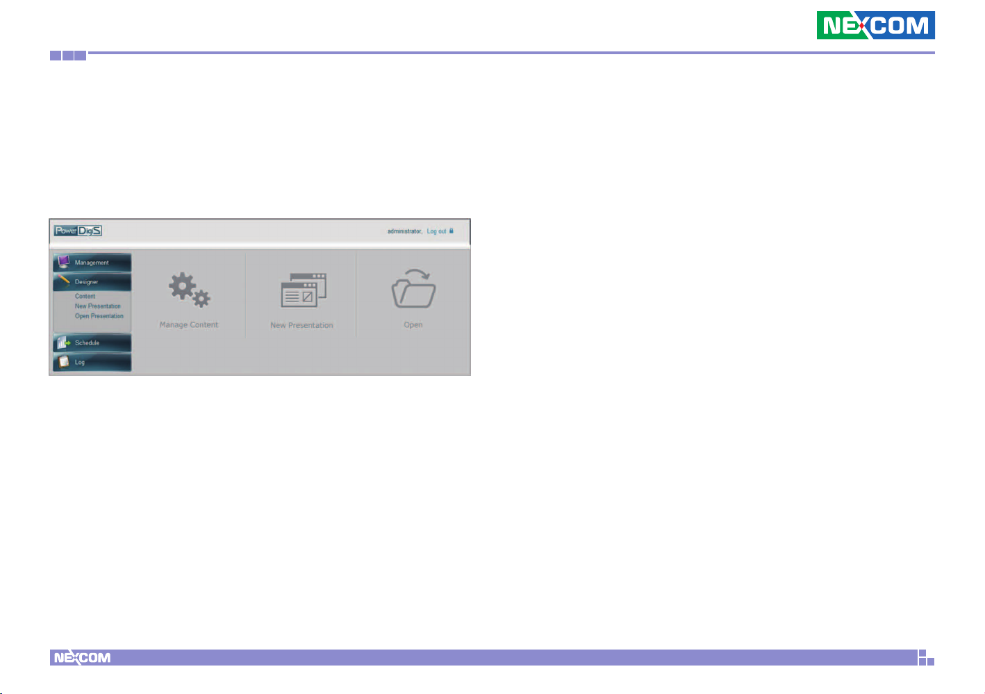
3.3.1 Designer Wizard
Designer Wizard allows user to manage content files, create a new
Presentation or edit an existing Presentation.
Copyright © 2012 NEXCOM International Co., Ltd. All Rights Reserved.
12
PowerDigis V2 Player User Manual
Page 16
Chapter 3: Player web management console
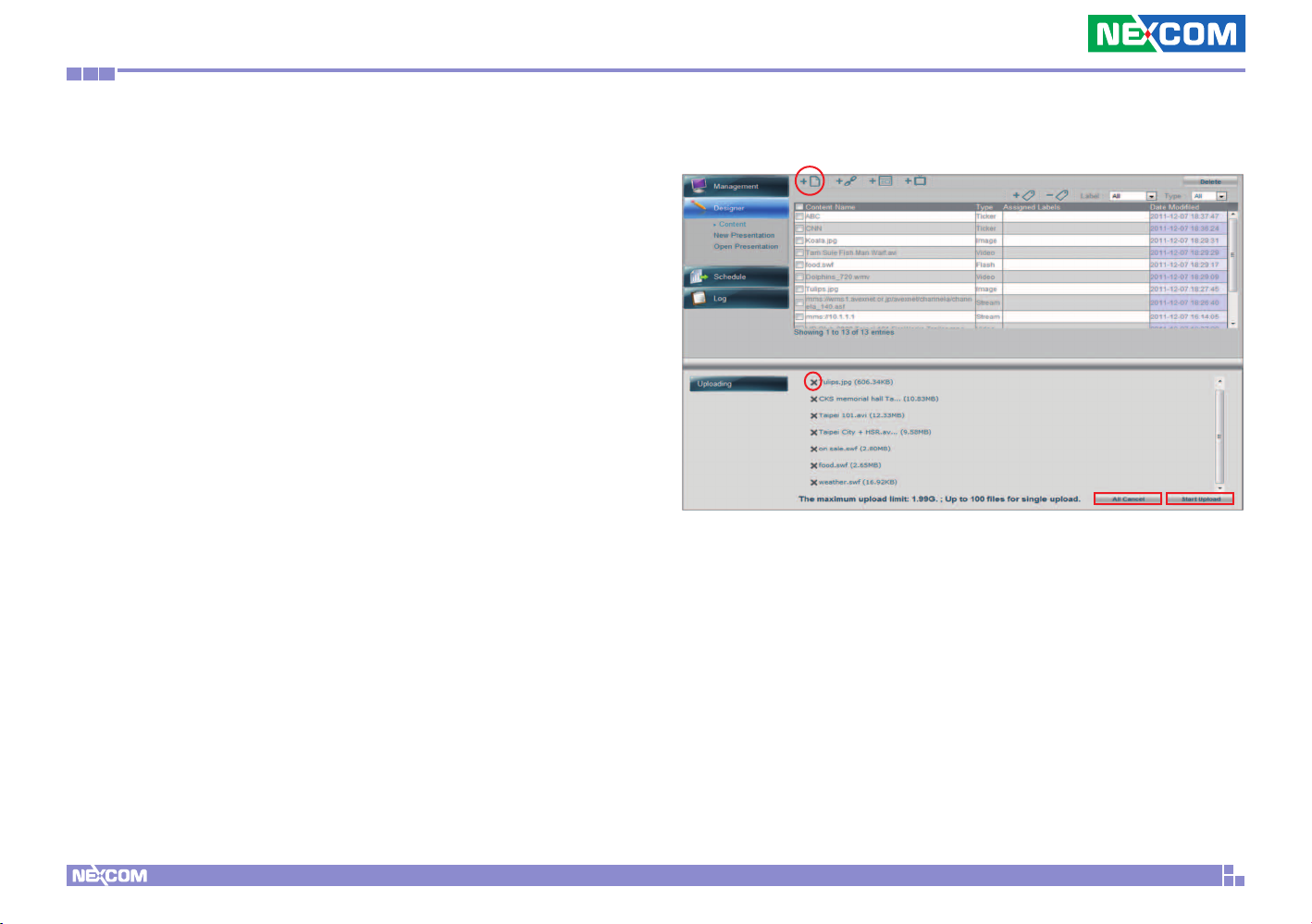
3.3.2 Manage Content
Click Manage Content to add new content files or manage the content
files you previously created.
Add Content from you local server
Step 1 Click “Add Content” icon at the top of the page
Step 2.Select any multimedia content file from your local storage . The
maximum upload limit is 1.99G and you can upload up to 100 files for
single upload.
Step 3. You can click “x” next to delete any content file or click All
Cancel button to delete all the selected files.
Step 4. Click Start Upload to upload the files.
Copyright © 2012 NEXCOM International Co., Ltd. All Rights Reserved.
13
PowerDigis V2 Player User Manual
Page 17
Chapter 3: Player web management console
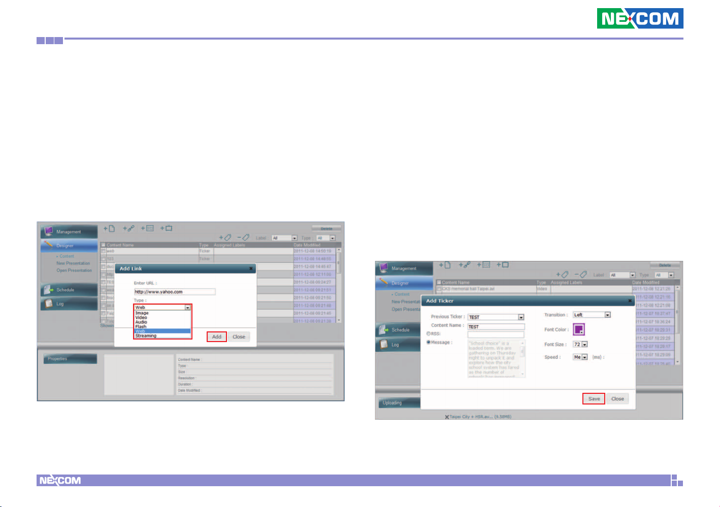
Add URL link
Step 1. Click “Add Link” icon at the top of the page
Step 2. Enter the URL link
Step 3. From the dropdown menu, select the URL type. Currently we
support Image, Video, Audio, Flash, Web and Streaming file formats.
Step 4. Click Add to add the link
Add Ticker
Step 1. Click “Add Ticker” icon on the top
Step 2. Enter the name of the ticker in the Content Name field
Step 3. You can either enter a RSS link or create your own message
content.
Step 4. Select the Transition effect, Font Color and Size and Speed for
the ticker
Step 5. Click Save
Copyright © 2012 NEXCOM International Co., Ltd. All Rights Reserved.
14
PowerDigis V2 Player User Manual
Page 18
Chapter 3: Player web management console
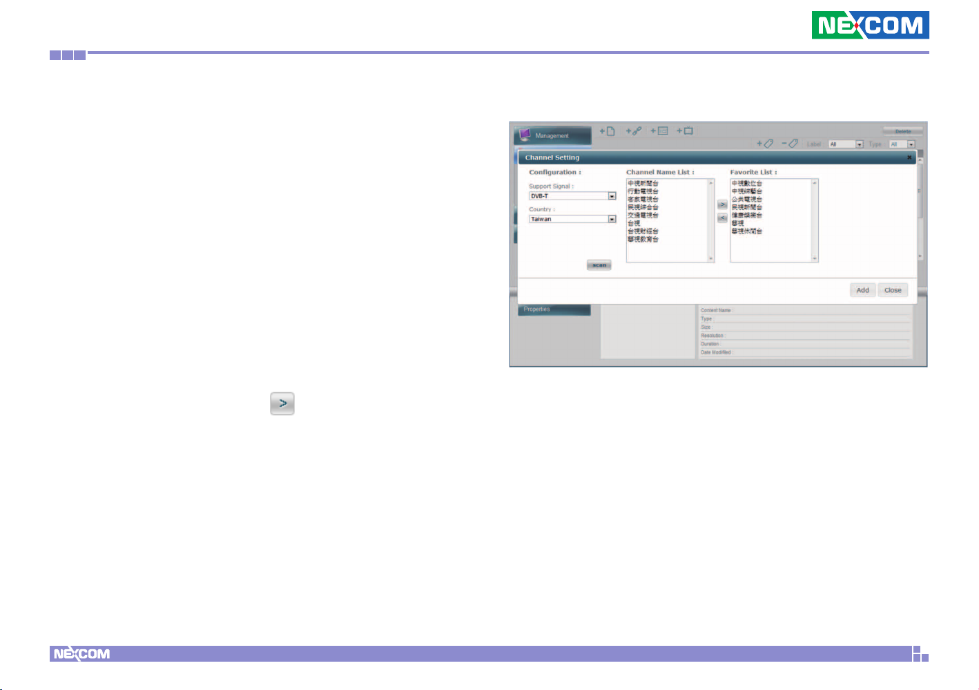
Add TV Channel
If you have purchased Nexcom TV Scanner Module, you can use TV
Channel Setting Tool to scan TV Channels and manage your favorite
channel list. Below steps will show you how to configure your TV
channel setting:
Step1. Select the compatible signal from Support Signal dropdown
menu. You can only select one signal at a time.
Step2. Select the country where the player is located. The
corresponding TV format will be automatically detected based on the
TV signal and country selected.
Step3. Click Scan. The scanned TV channels will be listed in the
Channel List.
Step4. You can add specific channels to your favorite channel list by
highlighting the channel and clicking
.
Step5. Click Add to allow your TV channel setting to take effect.
Copyright © 2012 NEXCOM International Co., Ltd. All Rights Reserved.
15
PowerDigis V2 Player User Manual
Page 19
Chapter 3: Player web management console
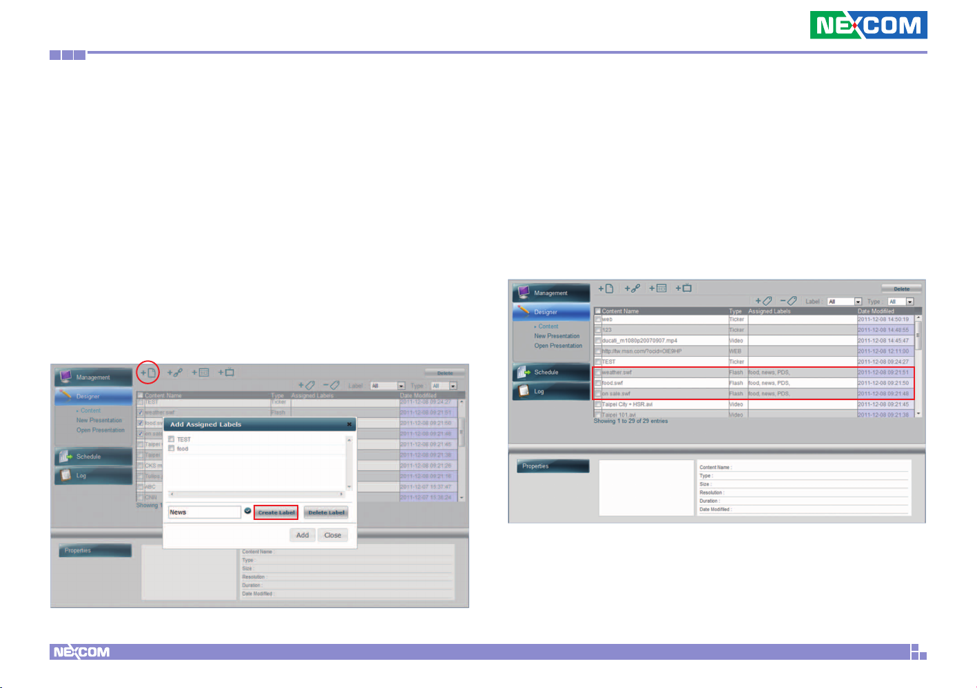
After all the content files are created, you can see them listed in the
content table. Follow the below steps to further label the content files if
necessary:
Add Labels
Step 1. From the content table, select the files to be labeled.
Step 2. Click “Add Labels” icon at the right top of the content table
Step 3. In the pop-up window, enter a new label name and click Create
Label button
Step 4. Repeat Step 3 to create more labels
Step 5. From the label list, select one more labels to be assigned to
previously selected content files. Click Add. You can see the assigned
labels listed in the content table.
Copyright © 2012 NEXCOM International Co., Ltd. All Rights Reserved.
16
PowerDigis V2 Player User Manual
Page 20
Chapter 3: Player web management console
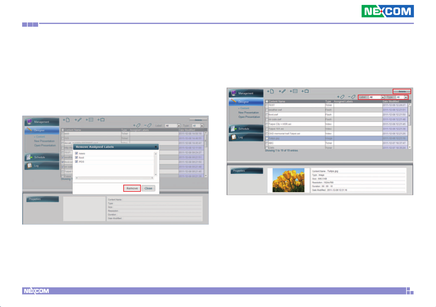
Remove labels
Step 1. From the content table, select the files to be un-labeled.
Step 2. Click “Remove Labels” icon at the right top of the content table
Step 3. From the label list, select the labels to be removed. Click
Remove button.
You can also choose to filter the files by label or file type. If you want
to delete a file, click Delete button at top-right of the page.
Copyright © 2012 NEXCOM International Co., Ltd. All Rights Reserved.
After you have done with content management, next you can proceed
with creating a new presentation or editing an existing presentation.
17
PowerDigis V2 Player User Manual
Page 21
Chapter 3: Player web management console
3.3.3 Creating/ Editing a New/ Existing
Presentation
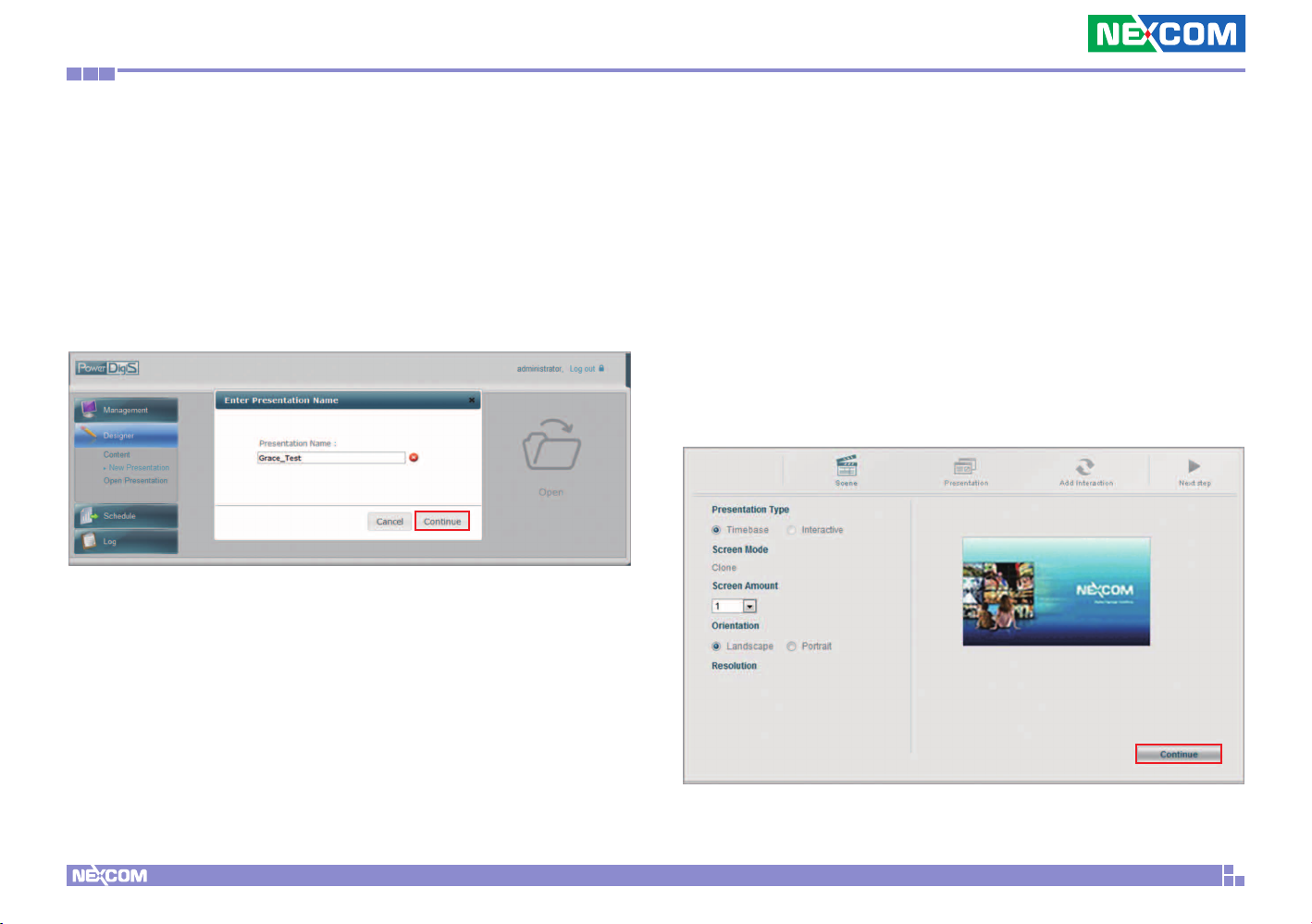
Creating a New Presentation
Step 1. Select “New Presentation”
Step 2. Enter Presentation Name and click Continue
Step 3. Select Presentation Type. (We will use time-based here as an
example.)
Step 4. Select Screen Amount. You can select up to 4 screens. (We will
use single screen here as an example.)
Step 5. Select Orientation (Landscape or Portrait)
Step 6. Click Continue to enter Scene Editor page
Copyright © 2012 NEXCOM International Co., Ltd. All Rights Reserved.
18
PowerDigis V2 Player User Manual
Page 22
Chapter 3: Player web management console
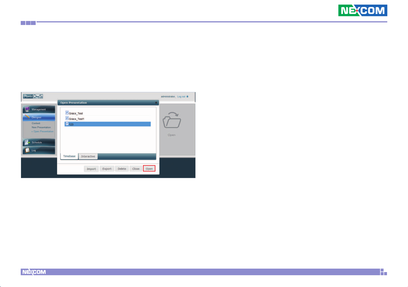
Editing an existing presentation
Step1. Select “Open”.
Step2. Select an existing presentation and click Open to directly go to
Scene Editor to edit your presentation.
Copyright © 2012 NEXCOM International Co., Ltd. All Rights Reserved.
19
PowerDigis V2 Player User Manual
Page 23
Chapter 3: Player web management console
3.3.4 Scene Editor
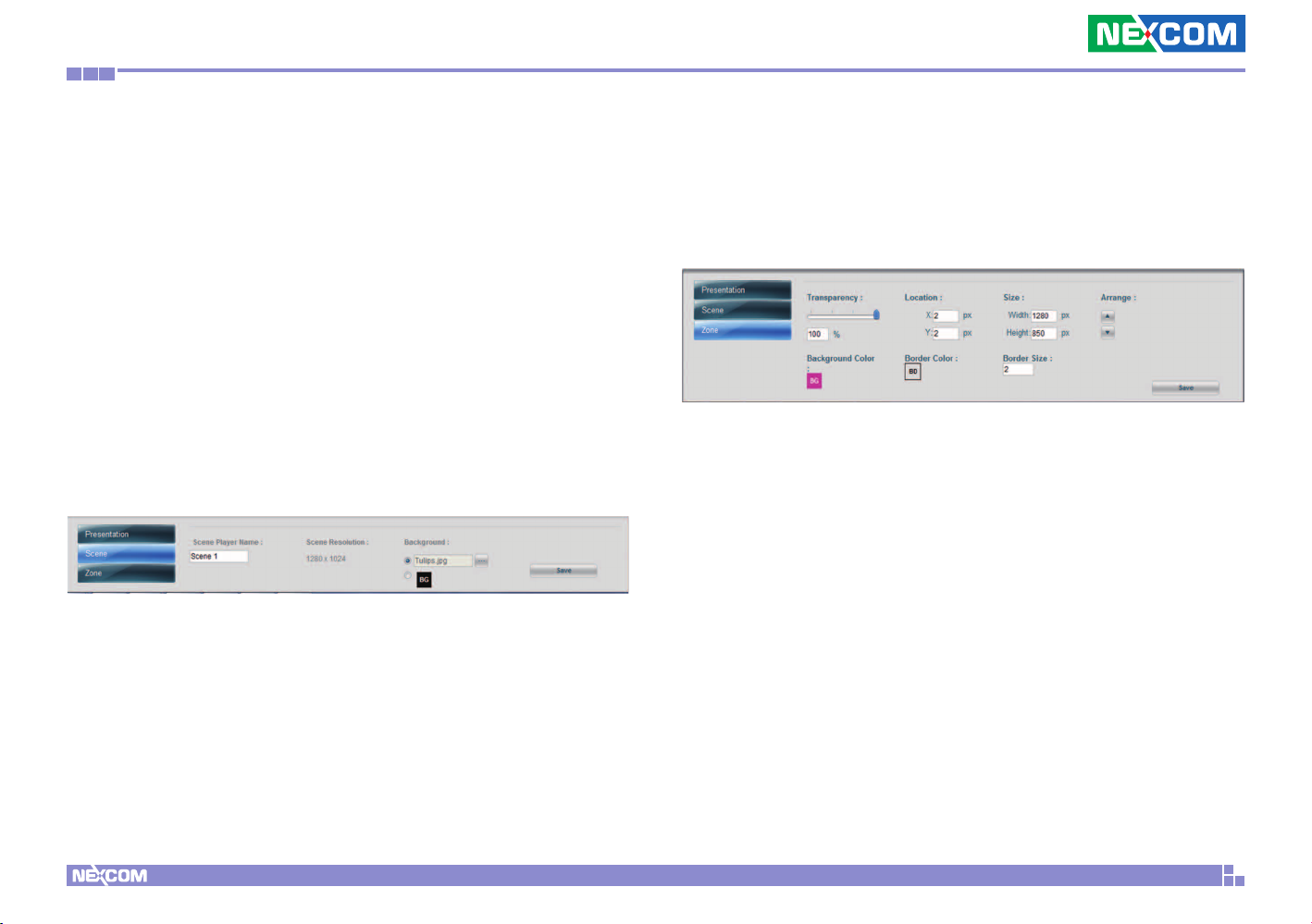
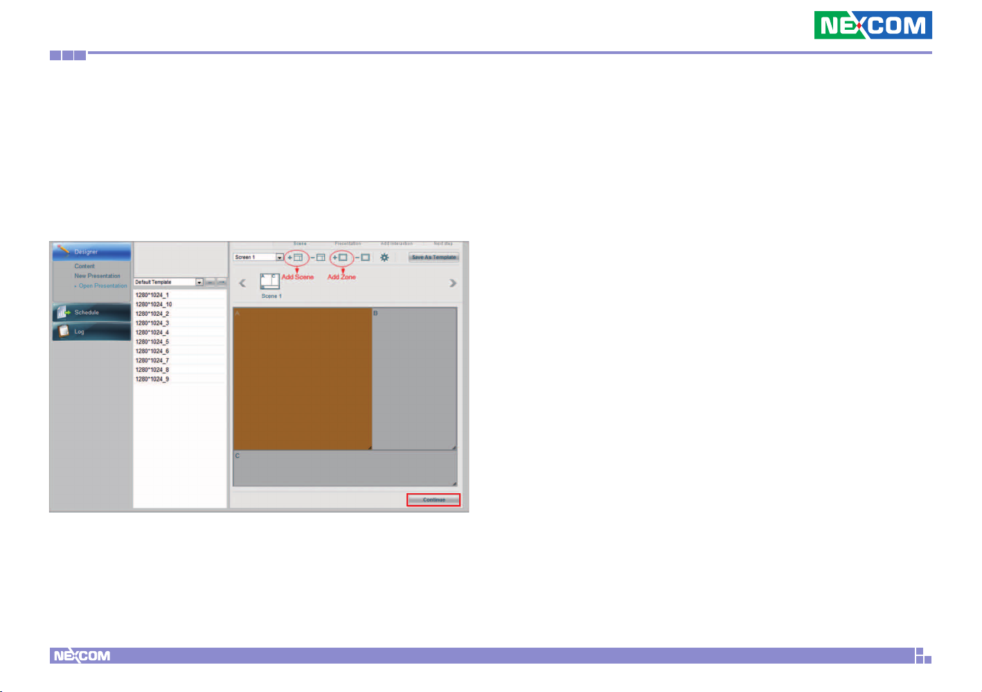
In Scene Editor, you can either create your own scenes with up to
9 zones in each Scene or simply choose scenes from the Default
Templates that best fit your layout design.
Step 1. Click Add Scene icon
Step 2. Click Add Zone icon to draw the first zone
Step 3. Repeat Step 1 & 2 to create more scenes and zones
Step 4. You can do further scene settings (Name your scene, change
the background image or color for your scene) by going to Scene
properties on the bottom of the page.
Step 5. You can adjust the zone size by either dragging the zone or go
to the Zone properties at the bottom of the page to do more further
settings.
Copyright © 2012 NEXCOM International Co., Ltd. All Rights Reserved.
20
PowerDigis V2 Player User Manual
Page 24
Chapter 3: Player web management console
Step 6. Click Delete Scene and Delete Zone icons to delete scenes/
zones if necessary
Step 7. Click “Save As Template” if you want to save the scene for
future use
Step 8. Click Continue to continue your content design
Copyright © 2012 NEXCOM International Co., Ltd. All Rights Reserved.
21
PowerDigis V2 Player User Manual
Page 25
Chapter 3: Player web management console
3.3.5 Content Design
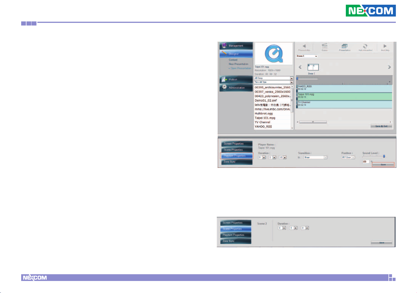
In Content Design page, you can easily drag & drop single or multiple
media content files to each zone and adjust the content playback
duration as desired. Here we will show you how to add the contents to
the layout you just created.
Add Contents to Zones
Step 1. From the Content List, select a video file previously created and
drag & drop to A zone.
Step 2. Select the image file previously created and drag & drop to B
zone
Step 3. Select the ticker previously created and drag & drop to C zone
Step 4. Adjust the content playback duration in each zone by dragging
the file with the mouse. Or manually enter the duration of each
playitem in the Playitem Properties.
Step 5. Repeat Step 1-4 to add more contents to the zone. Please note
you can only add the same type of contents in each zone.
Step 6. Click Save & Exit to finish content design
Step 7. Next select Schedule from the left function panel to schedule
your Presentation
Step 6. You can check the total duration of your scene in Scene
Properties at the bottom of the page.
Copyright © 2012 NEXCOM International Co., Ltd. All Rights Reserved.
22
PowerDigis V2 Player User Manual
Page 26
Chapter 3: Player web management console
3.4 Scheduling a Presentation
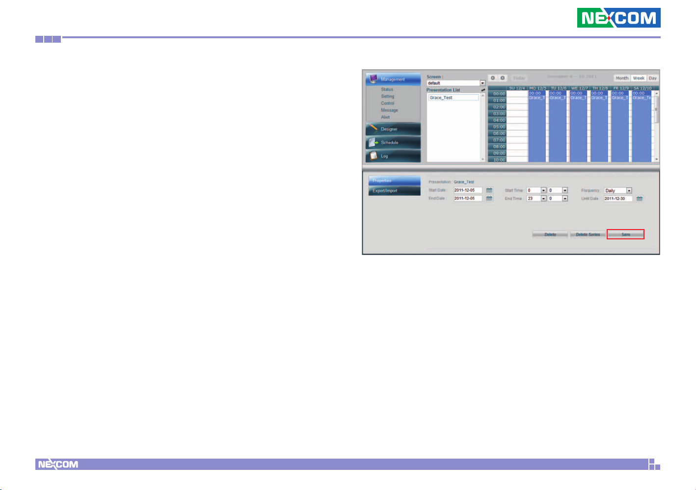
Schedule page allows you to schedule your presentation by screen.
You can drag and drop to schedule your presentation or single playlist
hourly, daily, monthly, annual as well as any specific time. You can also
select to view your schedule by day/week/month. Below is an example
to show you how to schedule the Presentation for a specific screen
from 0:00 to 23:00 with daily playback until the date you specify.
Step 1. From the Screen dropdown menu, select the screen to schedule
presentation with.
Step 2. From the Presentation List, select the presentation previously
created and then drag & drop to the specific time slot on the right.
Step 3. Drag down the bar to adjust the presentation playback
duration. Or select Presentation Start Date, End Date (2011-12-5), Start
Time and End Time. (0:00-23:00) in Schedule Properties below.
Step 3. Select “Daily” for playback frequency of the Presentation.
The presentation will be applied to Player according to the preset
schedule.
Step 4. Then select the date (2011-12-31) you want the frequency to
end.
Step 5. Click Save to save your schedule
Copyright © 2012 NEXCOM International Co., Ltd. All Rights Reserved.
23
PowerDigis V2 Player User Manual
Page 27
Chapter 3: Player web management console
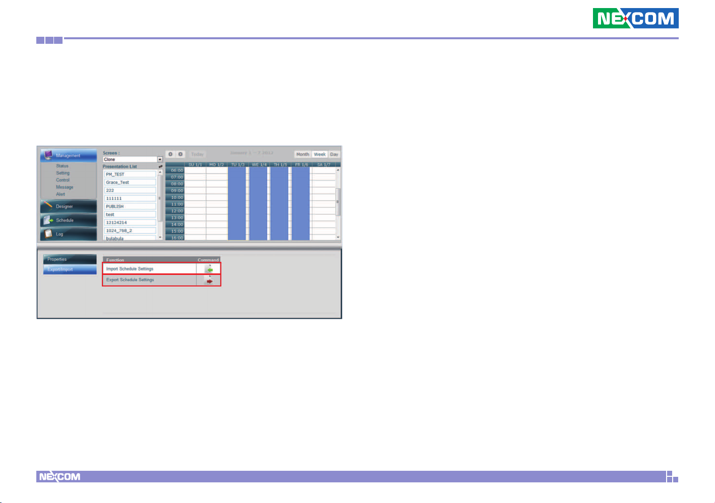
3.4.1 Export/Import a Schedule File
You can also export the schedule file to be applied to another Player or
import an existing schedule file to apply to this Player.
Copyright © 2012 NEXCOM International Co., Ltd. All Rights Reserved.
24
PowerDigis V2 Player User Manual
Page 28
Chapter 4: Advanced settings for player
Chapter 4: Player Web Management Console
4.1 Access Control List
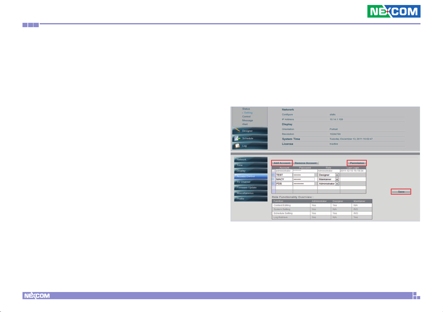
Access Control List provides role based access control for high security
of Player Management Console. Follow below steps to create an
account:
Step1. From Player Setting sub-menu, select Access Control.
Step2. Click Add Account button.
Step3. Enter account name and password.
Step4. Select the role to be assigned to this account. You can click
Permission to get an overview of each role functionality.
Step5. Repeat Step2-4 to add more accounts.
Step6. Click “x” if you want to delete an account
Step5. Click Save to save the setting
Copyright © 2012 NEXCOM International Co., Ltd. All Rights Reserved.
25
PowerDigis V2 Player User Manual
Page 29
Chapter 4: Advanced settings for player
4.2 TV Channel Setting
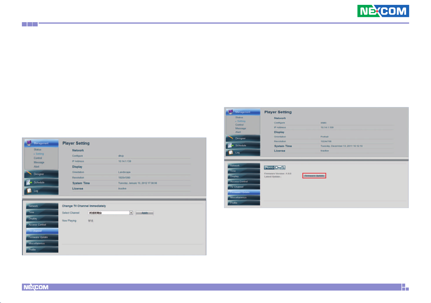
TV Channel setting provides you currently paying channel info and also
allows you to change the default channel immediately. To change the
default channel, follow below steps:
Step1. From the Channel dropdown menu, select a default channel
Step2. Click Apply. A pop-up window will appear confirming the
setting is successful.
4.3 Firmware Update
Firmware Update function provides current installed software version
and allows you to upgrade to a newer version by clicking Firmware
Update button. You can view update process in the Process Manager
table.
Copyright © 2012 NEXCOM International Co., Ltd. All Rights Reserved.
26
PowerDigis V2 Player User Manual
Page 30
Chapter 4: Advanced settings for player
4.4. Miscellaneous
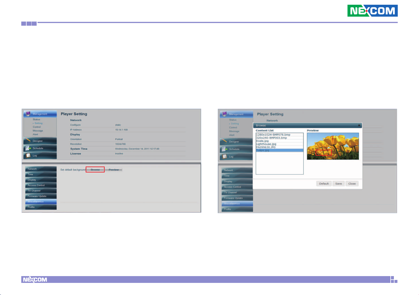
Miscellaneous contains extra settings for Player. Currently Change
default background image function is available. Follow these steps to
change Player default background image:
Step1. Click Browse
Step2. From the Content List, select an image to be Player default
background image.
Step3. Click Default to set the default background image.
Copyright © 2012 NEXCOM International Co., Ltd. All Rights Reserved.
27
PowerDigis V2 Player User Manual
Page 31
Chapter 4: Advanced settings for player
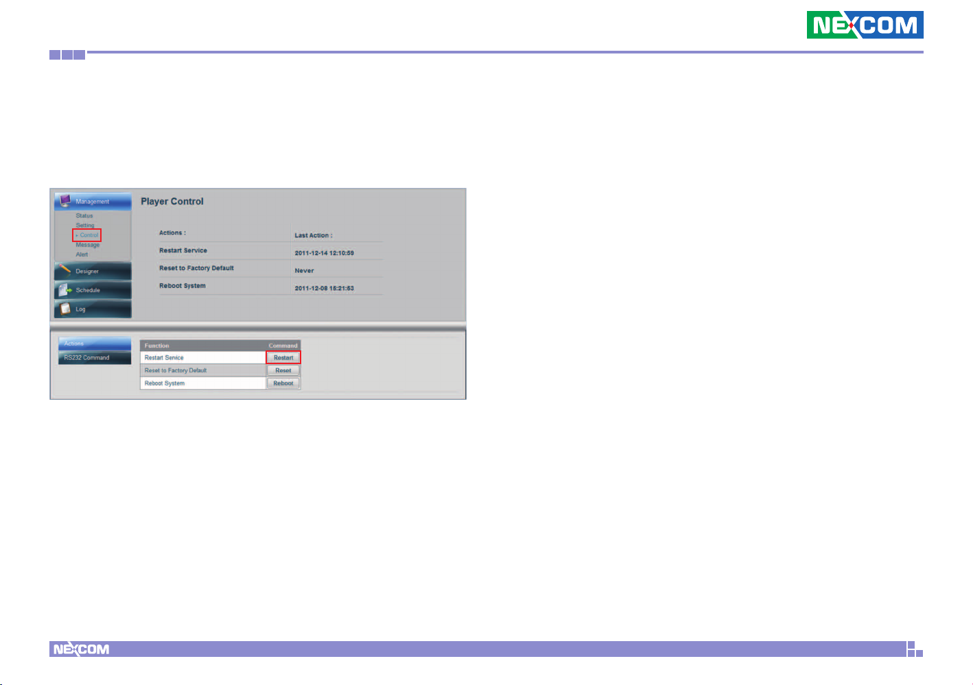
Step4. Go to the Management sub menu, click Control.
Step5. Click Restart to restart Player Service to make the setting take
effect.
Copyright © 2012 NEXCOM International Co., Ltd. All Rights Reserved.
28
PowerDigis V2 Player User Manual
Page 32
Chapter 4: Advanced settings for player
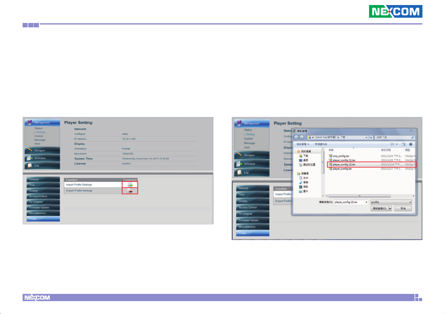
4.5 Import/Export Player Profile Settings
You can import an existing Player Signage Profile if you have
deployed multiple PowerDigiS player systems which all share the same
configuration. The Signage Profile should have been saved somewhere
in your local drive. You can also export current Player profile setting for
later use.
Copyright © 2012 NEXCOM International Co., Ltd. All Rights Reserved.
29
PowerDigis V2 Player User Manual
Page 33
Chapter 4: Advanced settings for player
4.6 Player Control
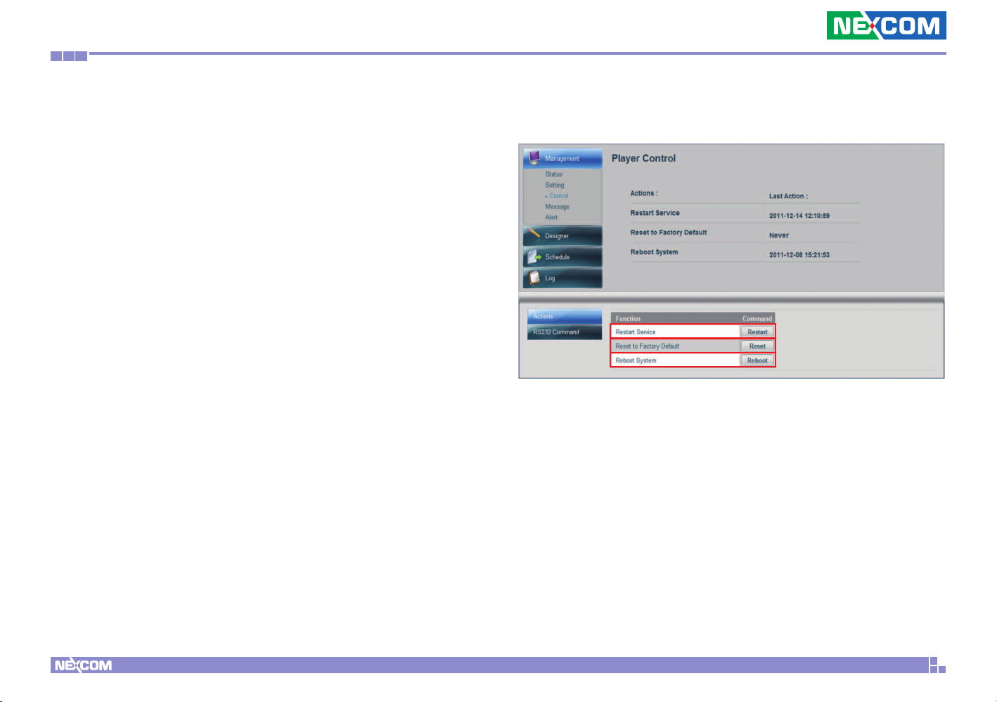
Player Control function allows you to control Player system, including
Restart Service, Reset to Factory Default, Reboot System and configure
RS232 Command setting.
4.6.1 Performing Player Actions
Follow below steps to perform Player actions:
Step1. Select Control from the Management sub menu
Step2. Click Actions button on the bottom of the page
Step3. Click Restart if you want to Restart Player Service
Step4. Click Reset if you want to Reset Player to Factory Default
Settings
Step5. Click Reboot to Reboot Player System
You can also view last Player actions time on this page.
Copyright © 2012 NEXCOM International Co., Ltd. All Rights Reserved.
30
PowerDigis V2 Player User Manual
Page 34
Chapter 4: Advanced settings for player
4.6.2 Configuring RS232 Command
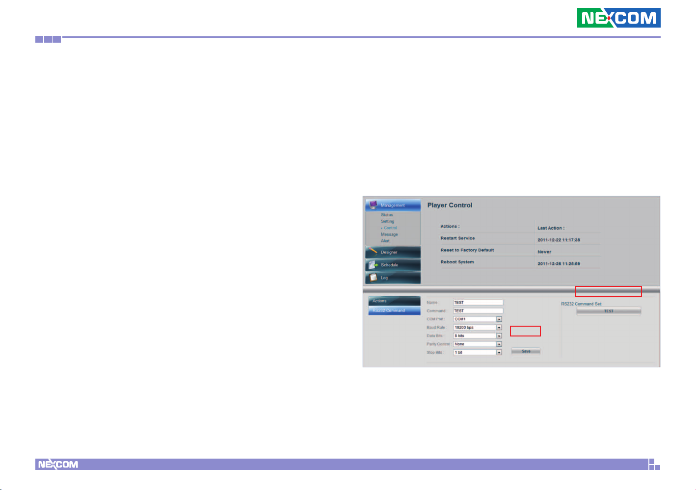
Follow below steps to configure RS232 command:
Step1.Click RS232 Command
Step2. Enter the name of RS232 command
Step3. Enter the command
Step4. From the COM Port dropdown menu, select the COM port to be
used.
Step5. From the Baud Rate dropdown menu, select the baud rate to be
used.
Step6. From the Data Bits dropdown menu, select the data bits to be
used.
Step7. From the Parity Control dropdown menu, select the parity
control type to be used.
Step8. From the Stop Bits dropdown menu, select the stop bits to be
used.
Step9. Click Save.
Step10. After you complete all the required setting for RS232 command
configuration, click TEST to verify if the RS232 command configuration
works.
Copyright © 2012 NEXCOM International Co., Ltd. All Rights Reserved.
31
PowerDigis V2 Player User Manual
Page 35
Chapter 4: Advanced settings for player
4.7 Player Message
If you need to display urgent message on the player monitor screen, the
Player Web Management Console allows you to send quick emergency
and notification messages to the Player through signage network in a
short time without the need to walk through the presentation design
and scheduling process
This feature can be applied to broadcast news, emergency message,
new advertisement or product promotion information at any given
time.
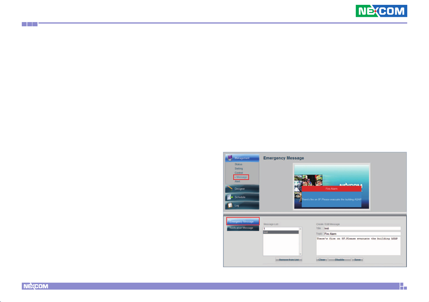
4.7.1 Composing Emergency Message
Follow below steps to compose an instant Emergency Message:
Step1. Select Message Under Management menu
Step2. Click Emergency Message button
Step3. Enter the Title name you want to save with this message
Step4. Enter the Topic name for this message
Step6. Click Save to save the message to the Message List
Step7. Click Enable to post the message to the Player display
immediately. You can also view how message appears on the top screen
picture.
Step8. Click Disable if you want to remove the message from the
display
Step5. Enter the message content
Copyright © 2012 NEXCOM International Co., Ltd. All Rights Reserved.
32
PowerDigis V2 Player User Manual
Page 36
Chapter 4: Advanced settings for player
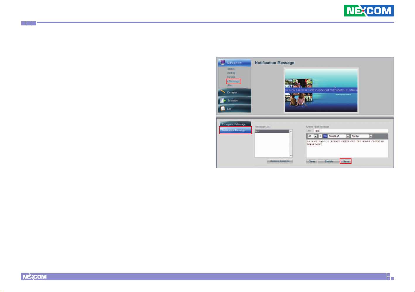
4.7.2 Composing Notification Message
Follow below steps to compose an instant Notification Message:
Step1. Select Message Under Management menu
Step2. Click Notification Message button
Step3. Enter the Title name you want to save with this message
Step4. Enter the message content
Step5. Select the font size, color, animation effect and where the
message should appear on the display. You can select Top, Center or
Bottom.
Step6. Click Save to save the message to the Message List
Step7. Click Enable to post the message to the Player display
immediately. You can also view how message appears on the top screen
picture.
Step8. Click Disable if you want to remove the message from the
display
Copyright © 2012 NEXCOM International Co., Ltd. All Rights Reserved.
33
PowerDigis V2 Player User Manual
Page 37
Chapter 4: Advanced settings for player
4.8 Player Alert
Player Alert page allows you configure Player Alert Setting as well as
Alert Email Notification Settings.
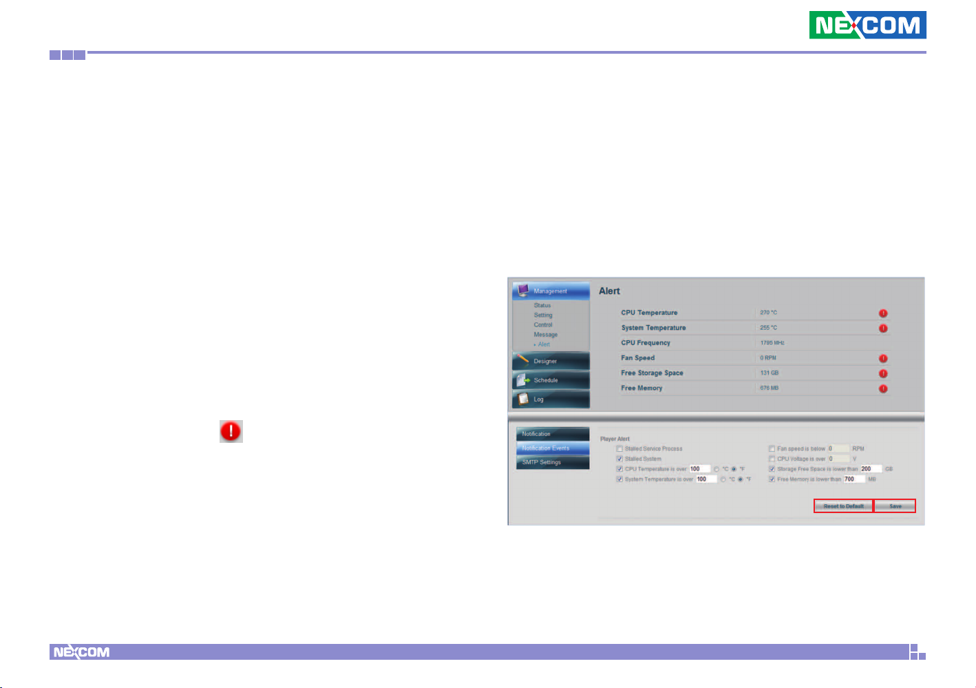
4.8.1 Configuring Alert Notification Event
Settings
Step 1. Select Alert under Management menu
Step 2. Click Notification Events button
Step 3. Check the Player Alert Events you want to be notified. Enter the
normal value range for the Events.
Step 4. Click Save to save the settings. If any Player event value is out
of normal range, you will see
on the top of the page.
appear next to the abnormal events
Step 5. If you want to reset the settings back to the default, click Reset
to Default button.
Copyright © 2012 NEXCOM International Co., Ltd. All Rights Reserved.
34
PowerDigis V2 Player User Manual
Page 38
Chapter 4: Advanced settings for player
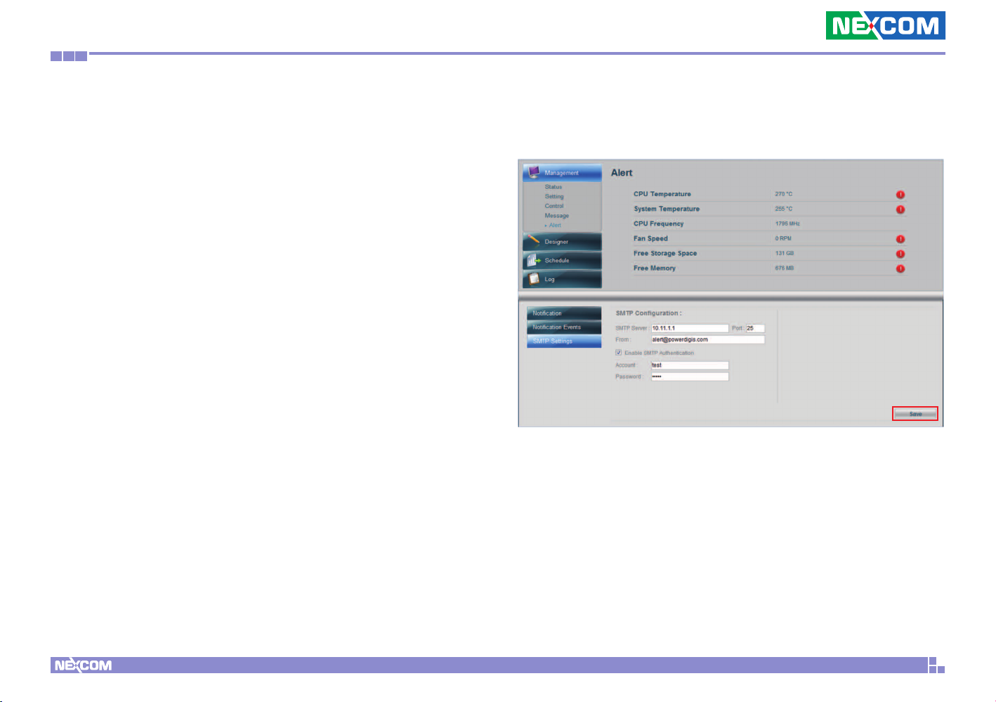
4.8.2 Configuring Alert Email Notification
Settings
Step 1. Click SMTP Settings
Step 2. Enter SMTP server relevant info.
Step 3. Click checkbox if you want to Enable SMTP Authentication
Step 4. Type in Account name and Password
Step 5. Click Save to save the setting
Copyright © 2012 NEXCOM International Co., Ltd. All Rights Reserved.
35
PowerDigis V2 Player User Manual
Page 39
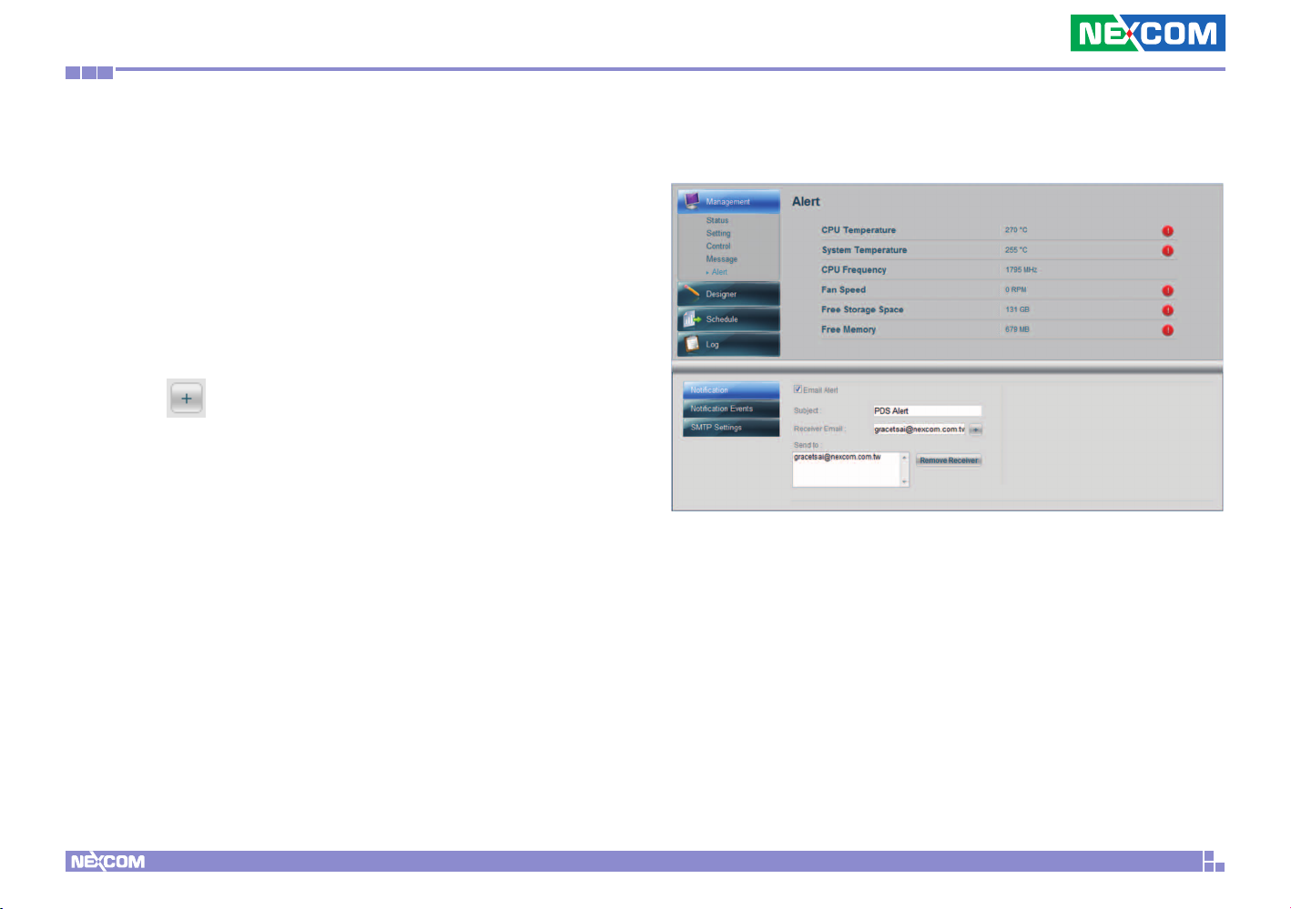
Chapter 4: Advanced settings for player
4.8.3 Enabling Alert Email Settings
Step 1. Select Notification
Step 2. Check Email Alert to enable email alert setting
Step 3. Enter the Subject of the Email Alert
Step 4. Type in the recipient’s email address to have them receive the
alert email
Step 5. Click
to add the email recipients into the Send to List
Step 6. Highlight any email recipient email and click Remove Recipient
if you want to remove it from the list.
Copyright © 2012 NEXCOM International Co., Ltd. All Rights Reserved.
36
PowerDigis V2 Player User Manual
Page 40
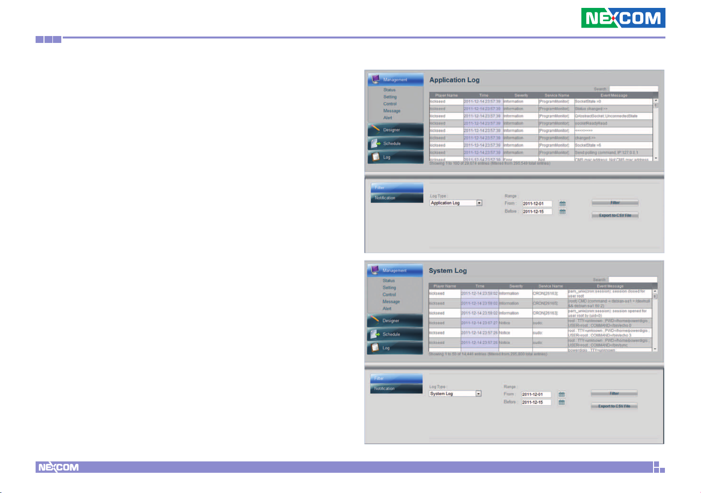
Chapter 4: Advanced settings for player
4.9 Player Log
Log page provides you with information on different types of Player
Logs, including Application Log, System Log and Proof of Play
messages. You can select to view all messages or just a particular type
of message by filtering messages with a specified date range.
4.9.1 Application/ System Log
Application and System Logs provide you with important info on Player
application and system events.
To view Application/System logs, follow below steps:
Step 1. Select Log from the left main functional panel
Step 2. From the Log Type dropdown menu, select Application Log/
System Log
Step 3.Enter the date range to filter the log within a specific time
period
Step 4. Click Filter. You can view the filtered log raw data appearing on
the top of the page
Step 5. If you want to save the logs to your local machine, click Export
to CSV File to export the logs into a csv file.
Copyright © 2012 NEXCOM International Co., Ltd. All Rights Reserved.
37
PowerDigis V2 Player User Manual
Page 41
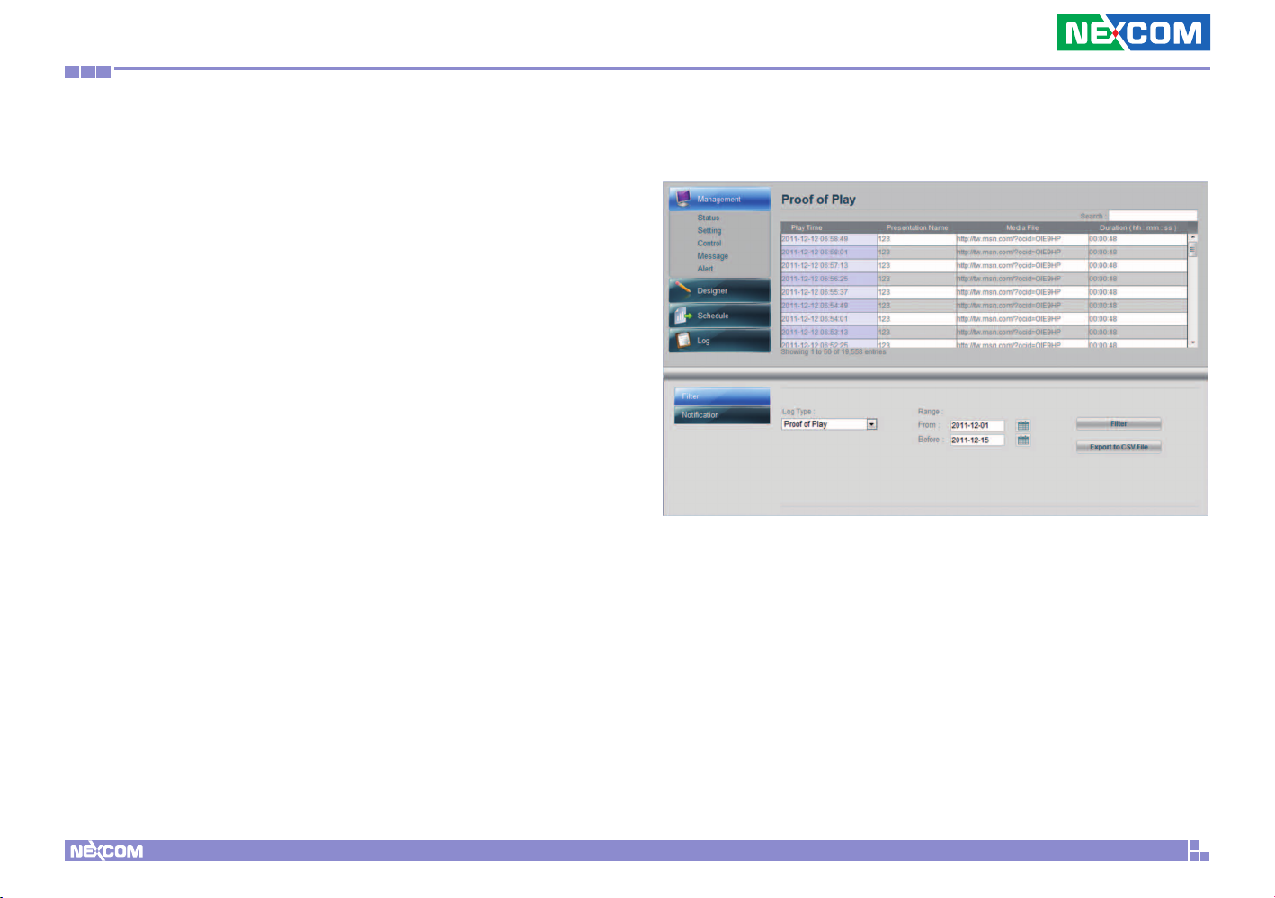
Chapter 4: Advanced settings for player
4.9.2 Proof of Play
Proof of play is the term used in digital signage to record presentation
playback summary and raw play logs which keep track of what content
file was played as well as the date and time when it was played and the
playback duration.
To view proof of Play logs, follow below steps:
Step 1. From the Log Type dropdown menu, select Proof of Play
Step 2. Refer to Step 3-5 in Viewing Application/System Event Logs to
filter and export the log to you local machine.
Copyright © 2012 NEXCOM International Co., Ltd. All Rights Reserved.
38
PowerDigis V2 Player User Manual
Page 42
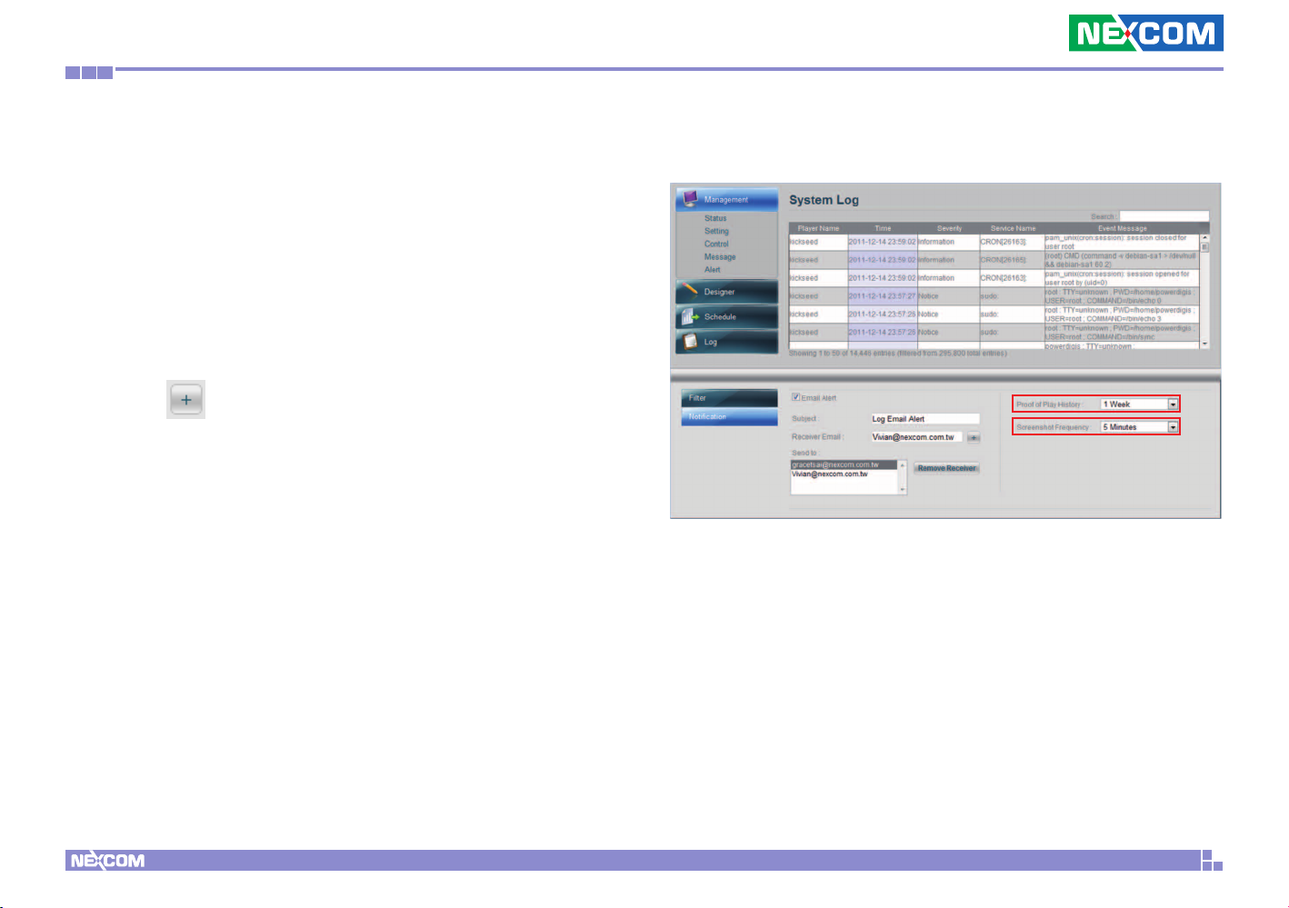
Chapter 4: Advanced settings for player
4.9.3 Enabling Log Email Alert Setting
Step 1. Select Notification
Step 2. Check Email Alert to enable log email alert setting
Step 3. Enter the Subject of the Log Email Alert
Step 4. Type in the recipient’s email address to have them receive the
log alert email
Step 5. Click
to add the email recipients into the Send to List
Step 6. Highlight any email recipient email and click Remove Recipient
if you want to remove it from the list.
Step 7.From the Proof of Play History dropdown menu, select the
time you want to keep Proof of Play logs. You can keep them up to 2
months. The old messages will be cleaned up automatically afterwards.
Step 8. If you want to take screenshot of your Player display activity,
you can select the time interval from the Screenshot Frequency
dropdown menu. The minimum and maximum intervals are 1 minute
and 5 minutes.
Step 9. Select Disable if you do not want the screenshot activity to
occur.
Copyright © 2012 NEXCOM International Co., Ltd. All Rights Reserved.
39
PowerDigis V2 Player User Manual
Page 43
Chapter 5: Interactive Presentation Design & License Upgrade
Chapter 5: Interactive Presentation Design & License
Upgrade
5.1 Interactive Presentation Design
Our Designer not only allows user to create an time-based presentation,
but also gives user flexibility to create an interactive presentation using
Event Trigger tree list. With this feature, you can predefine different trigger
methods and correspondingly triggered events for your presentation.
Currently we support touch and GPS events.
Below are steps that show you how to create these specific triggered
events.
5.1.1 Interactive Presentation Design
Access Control List provides role based access control for high security of
Player Management Console. Follow below steps to create an account:
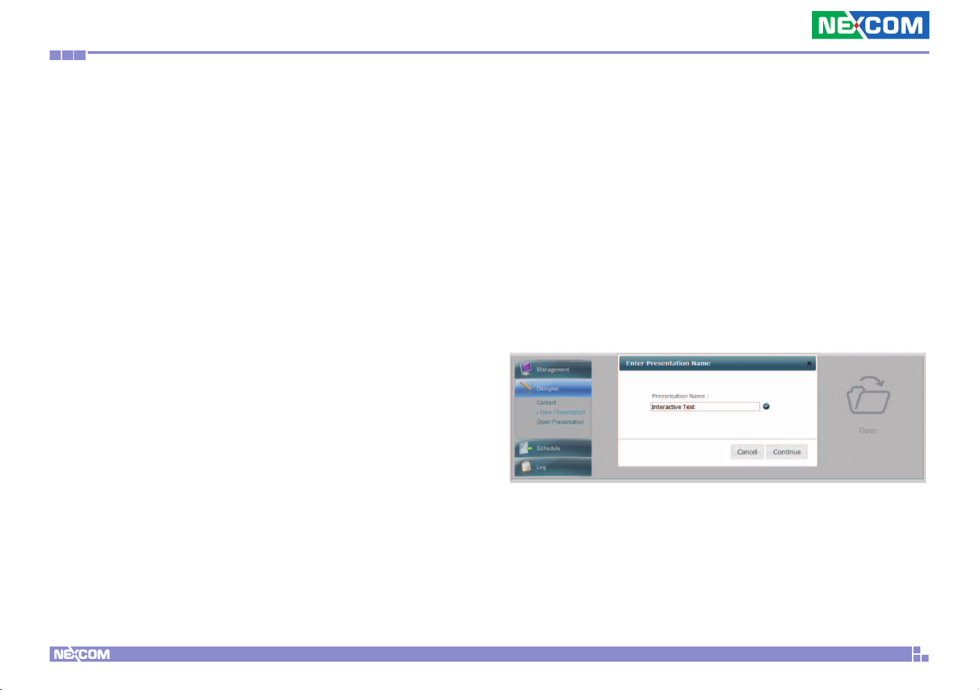
Step 1. Open Designer and select “New Presentation”.
Step 2. Enter Presentation Name and click Continue.
Copyright © 2012 NEXCOM International Co., Ltd. All Rights Reserved.
40
PowerDigis V2 Player User Manual
Page 44
Chapter 5: Interactive Presentation Design & License Upgrade
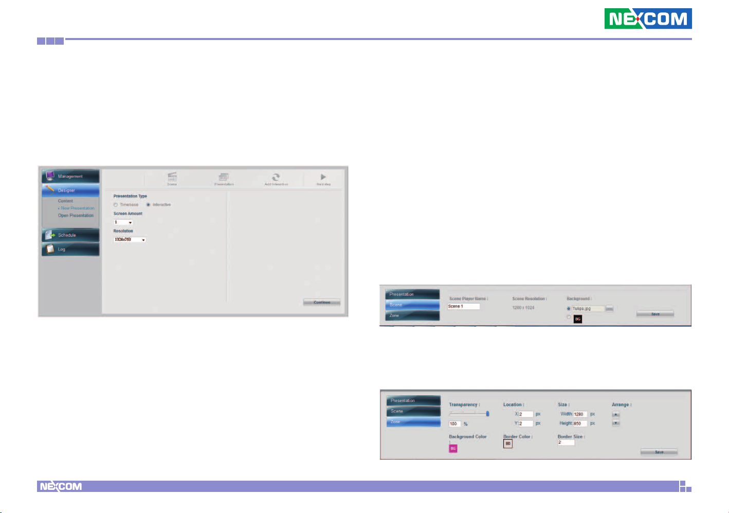
Step 3. Select Interactive for Presentation Type.
Step 4. Select Screen Amount. You can select up to 4 screens. (We will
use single screen here as an example.)
Step 5. Click Continue to enter Scene Editor page.
5.1.2 Scene Editor
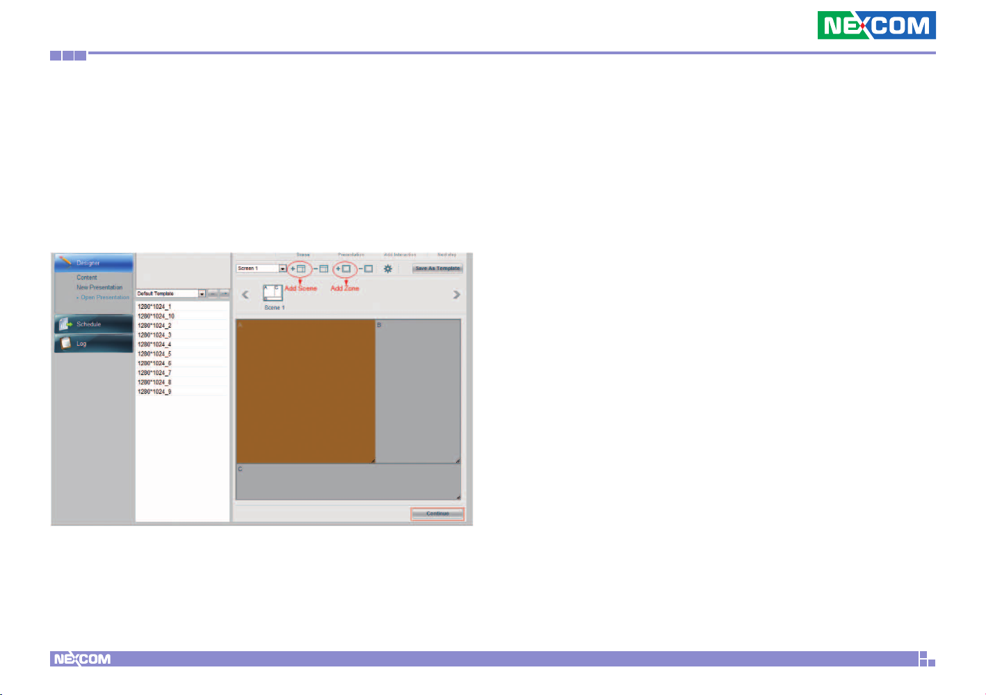
In Scene Editor, you can either create your own scenes with up to 9 zones
in each Scene or simply choose scenes from the Default Templates that best
fit your layout design.
Step 1. Click Add Scene icon.
Step 2. Click Add Zone icon to draw the first zone.
Step 3. Repeat Step 1 & 2 to create more scenes and zones.
Step 4. You can do further scene settings (Name your scene, change
the background image or color for your scene) by going to Scene
properties on the bottom of the page.
Step 5. You can adjust the zone size by either dragging the zone or go
to the Zone properties at the bottom of the page to do more further
settings.
Copyright © 2012 NEXCOM International Co., Ltd. All Rights Reserved.
41
PowerDigis V2 Player User Manual
Page 45
Chapter 5: Interactive Presentation Design & License Upgrade
Step 6. Click Delete Scene and Delete Zone icons to delete scenes/zones
if necessary.
Step 7. Click “Save As Template” if you want to save the scene for future
use.
Step 8. Click Continue to continue your content design.
Copyright © 2012 NEXCOM International Co., Ltd. All Rights Reserved.
42
PowerDigis V2 Player User Manual
Page 46
Chapter 5: Interactive Presentation Design & License Upgrade
5.1.3 Content Design
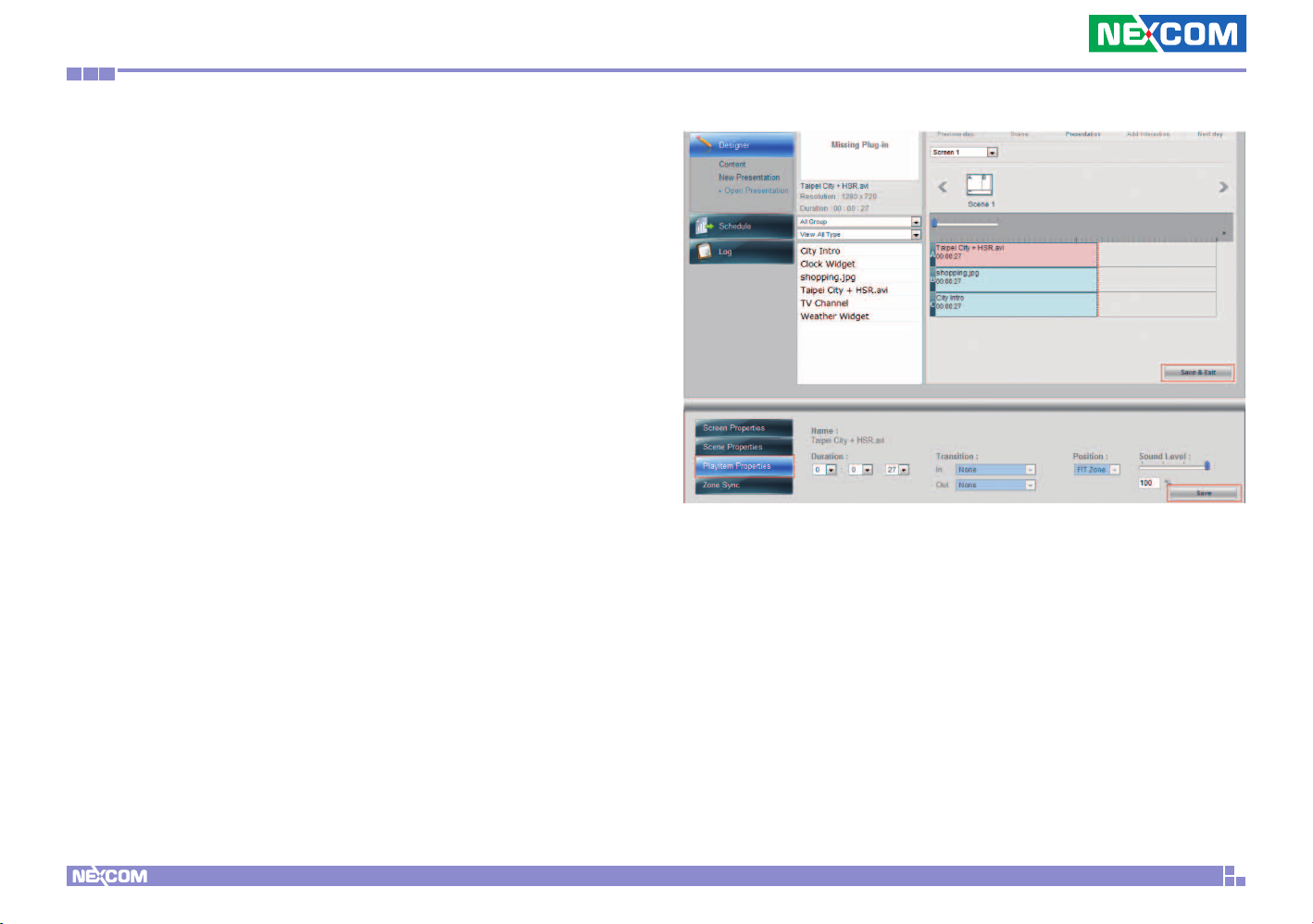
In Content Design page, you can easily drag & drop single or multiple media
content files to each zone and adjust the content playback duration as
desired. Here we will show you how to add the contents to the layout you
just created.
Add Contents to Zones
Step 1. From the Content List, select a video file previously created and
drag & drop to A zone.
Step 2. Select the image file previously created and drag & drop to B zone.
Step 3. Select the ticker previously created and drag & drop to C zone.
Step 4. Adjust the content playback duration in each zone by dragging the
file with the mouse. Or manually enter the duration of each playitem in
the Playitem Properties.
Copyright © 2012 NEXCOM International Co., Ltd. All Rights Reserved.
Step 5. Repeat Step 1-4 to add more contents to the zone. Please note
you can only add the same type of contents in each zone.
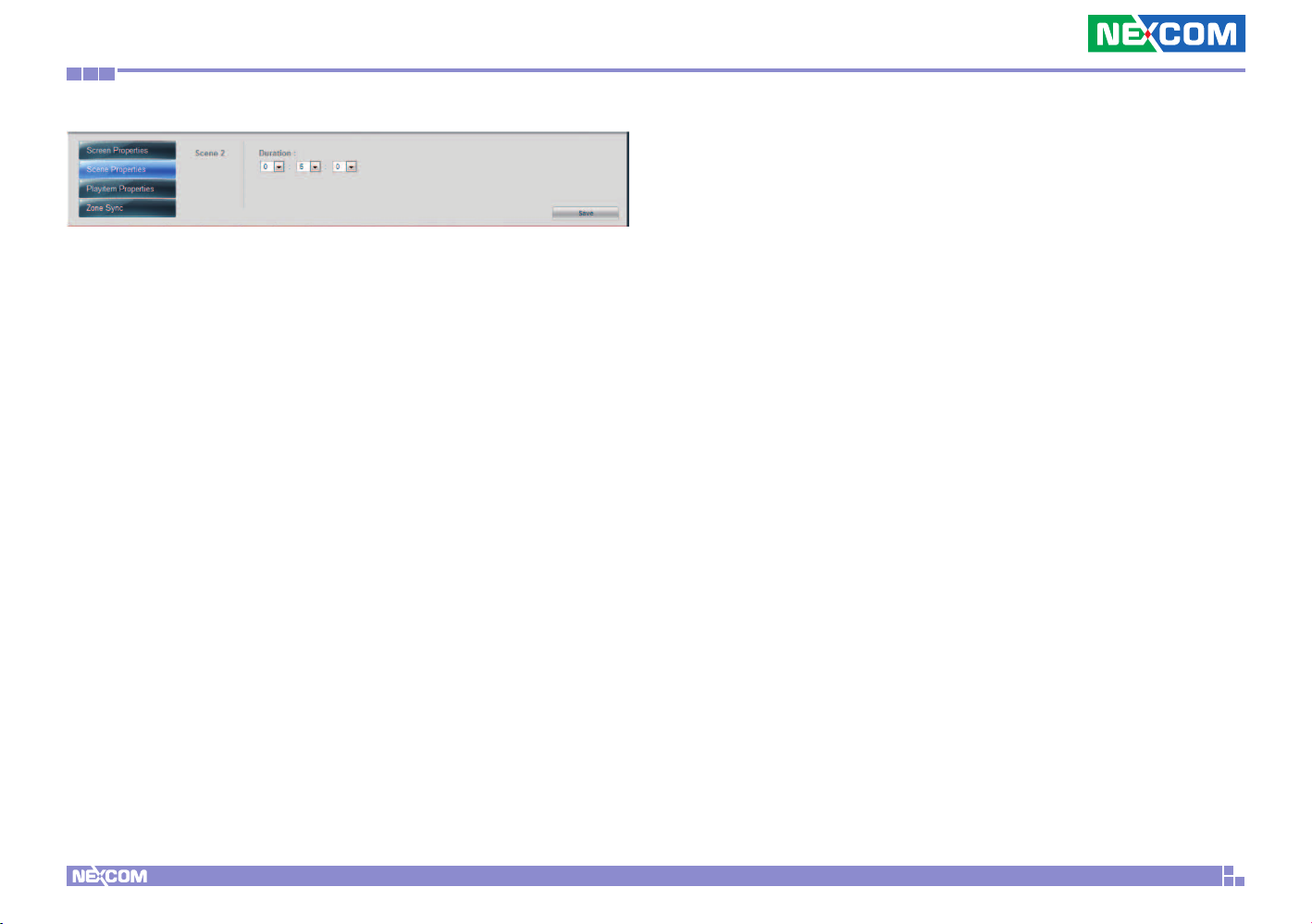
Step 6. You can check the total duration of your scene in Scene
Properties at the bottom of the page.
43
PowerDigis V2 Player User Manual
Page 47
Chapter 5: Interactive Presentation Design & License Upgrade
Step 7. Click Save & Exit to finish content design.
Step 8. Next select Schedule from the left function panel to schedule
your Presentation.
Copyright © 2012 NEXCOM International Co., Ltd. All Rights Reserved.
44
PowerDigis V2 Player User Manual
Page 48
Chapter 5: Interactive Presentation Design & License Upgrade
5.1.4 Event Trigger Tree List
After you have done with scene editing and content design, you can go
on with interactive presentation design using Event Trigger Tree List on the
next page. We will give an example here to show you how to create an
interactive presentation with predefined touch and GPS event settings.
Create Touch Events
The user-friendly GUI allows you to define active areas and corresponding
actions. When user touches the touch screen, it sends a command to
Player and triggers the playback of the pre-defined playlist. Follow below
steps to create touch events:
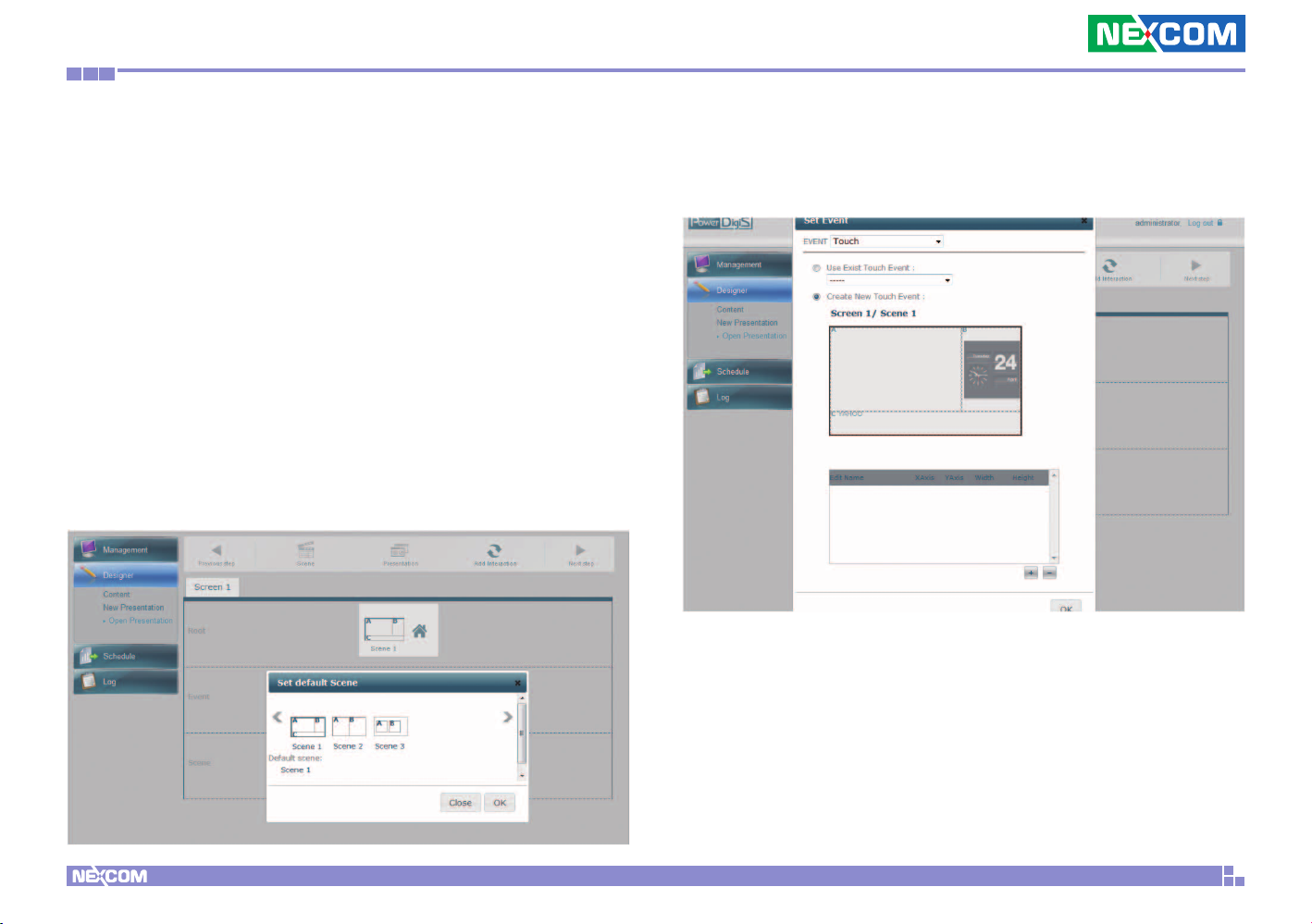
Step 1. Click home icon in the root layer to set the default scene. Default
scene is the home scene where the sequential events can be triggered from.
Step 2. Then click the default scene to set the event. From the Event
Type dropdown menu, select Touch. The touch event setting window
will appear as below. From this window, you can create multiple touch
areas on the scene and adjust their location and size.
Copyright © 2012 NEXCOM International Co., Ltd. All Rights Reserved.
45
PowerDigis V2 Player User Manual
Page 49
Chapter 5: Interactive Presentation Design & License Upgrade
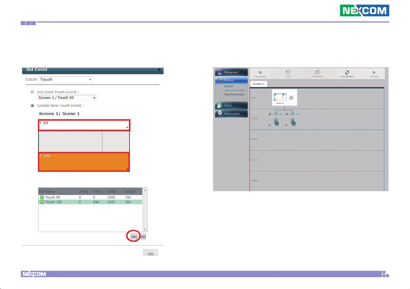
Step 3. Click “Add” icon to add a touch area on the scene. You can
drag the mouse to adjust the location and the size of the touch area.
Repeat this step to create more touch areas.
Step 4. Click OK. You will see the touch events you created appear in
the Event Trigger tree list.
Copyright © 2012 NEXCOM International Co., Ltd. All Rights Reserved.
46
PowerDigis V2 Player User Manual
Page 50
Chapter 5: Interactive Presentation Design & License Upgrade
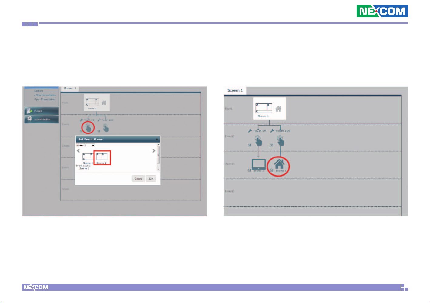
Step 5. From the Event Trigger list, click the touch even icon you just
created and select the triggered scene from the Set Event Scene pop-up
window. Then Click OK.
Step 6. Repeat Step 5 to set event scene for other touch events
created.
Note: if you select default scene as a event scene, then it will lead you
back to the default/home scene.
Copyright © 2012 NEXCOM International Co., Ltd. All Rights Reserved.
47
PowerDigis V2 Player User Manual
Page 51
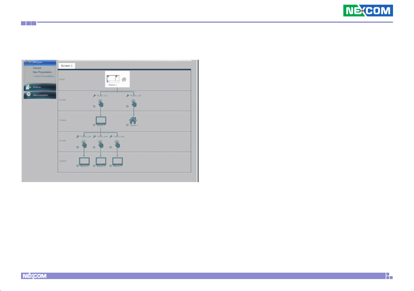
Chapter 5: Interactive Presentation Design & License Upgrade
Step 7. You can then click the event scene to create more touch events
and trigger scenes as below.
Copyright © 2012 NEXCOM International Co., Ltd. All Rights Reserved.
48
PowerDigis V2 Player User Manual
Page 52
Chapter 5: Interactive Presentation Design & License Upgrade
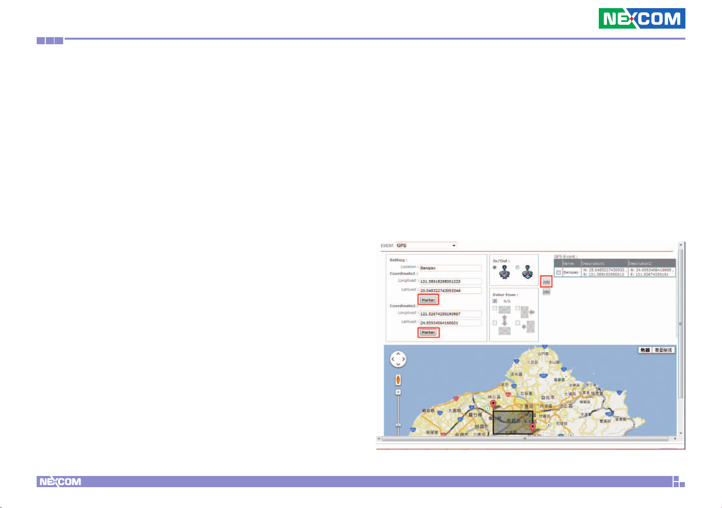
Create GPS Events
In addition to touch events, you can also create GPS events in the same
interactive presentation. GPS technology integration provides excellent
location-based digital signage. User can define playlists for each location on
the Google map to be displayed in moving vehicles. Follow below steps to
create GPS events.
Step 1. Click the default scene icon in the Root Layer to set a new event.
Step 2. From the Event Type dropdown menu, select GPS.
Step 3. Enter the GPS event name in the Event field.
Step 4. You can either manually enter the values of Longitude & Latitude
of this location or simply drag the Coordinate on Google Map to define
the area of the GPS event.
If you choose to manually enter the Longitude & Latitude values, make
sure to click “Marker” to fix Coordinate 1 & 2.
Step 5. Next you can select “In or Out” of this GPS event. “In” means
the event will be triggered if the vehicle enters this area while “Out”
means the event will be trigger when the vehicle exit from this area.
Step 6. Then you can select which from which direction the vehicle
enters/exits from this area the event will be triggered. You can select
“N/A” if no specific direction is defined or North, South, East, West or
multiple directions if required.
Step 7. Click “Add” icon to add this event to the GPS Event list on the
right.
If you choose to drag the Coordinate on the map, click Coordinate1 first to
drag to specific spot and then click Coordinate 2 to define the GPS event
area.
Copyright © 2012 NEXCOM International Co., Ltd. All Rights Reserved.
49
PowerDigis V2 Player User Manual
Page 53
Chapter 5: Interactive Presentation Design & License Upgrade
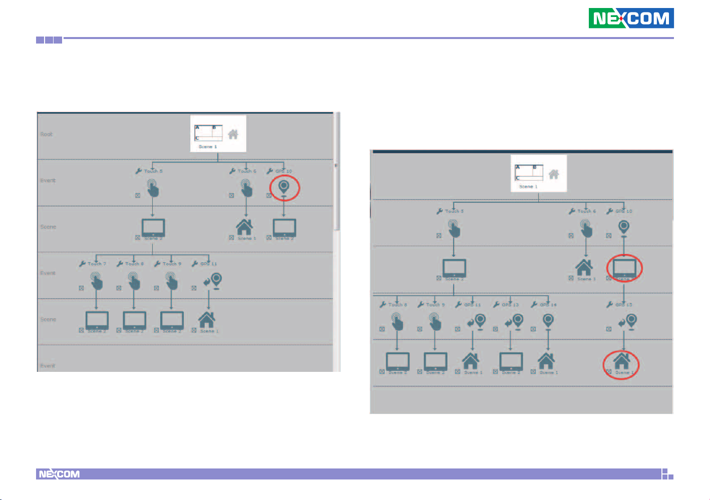
Step 8. You can see the GPS event you created appear in the Event
Trigger tree list. Click the event to select the triggered scene.
Step 10. You can also click the event scene to create more GPS events
and trigger scenes as below.
Note: if you select default scene as an event scene, then it will lead you
back to the default/home scene.
Step 9. Repeat above steps to create more GPS events and
correspondent triggered scenes.
Copyright © 2012 NEXCOM International Co., Ltd. All Rights Reserved.
50
PowerDigis V2 Player User Manual
Page 54
Chapter 5: Interactive Presentation Design & License Upgrade
5.2 License Upgrade
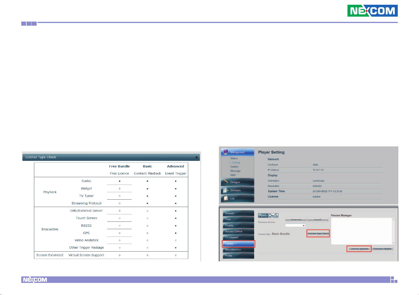
Currently there are three licensing packages for PDS user to choose from:
•Free Bundle – Free purchase. Supports free media playback codec.
•Basic Bundle (Content Playback) – Includes various media codec, TV
tuner and streaming protocols support.
•Advanced Bundle (Event Trigger) – Integrates with Event Trigger
functions, including touch and GPS interactive presentation design.
Please contact Nexcom sales if you wish to change/upgrade your Player
license. After your request has been confirmed, you can do online license
upgrade through Player management console or offline upgrade.
5.2.1 Online License Upgrade
Follow below steps to upgrade Player license:
Step 1. Click “Update”. You can see the current license type for the Player.
Step 2. Click “License Type Check” if you want to check special features
each license has to offer.
Step 3. Click License Upgrade to upgrade Player license type.
Copyright © 2012 NEXCOM International Co., Ltd. All Rights Reserved.
51
PowerDigis V2 Player User Manual
Page 55
Chapter 5: Interactive Presentation Design & License Upgrade
5.2.2 Offline License Upgrade
If there is no network setting configured for your Player, please contact
Nexcom sales for offline license upgrade procedure.
Copyright © 2012 NEXCOM International Co., Ltd. All Rights Reserved.
52
PowerDigis V2 Player User Manual
 Loading...