

Page 1

NEX 6620A User's Guide Rev. B0 0301
NEX 6620A
ATX Industry Server Board
User′′′′s Guide
NEXCOM
Page 2

NEX 6620A User's Guide Rev. B0 0301
@Copyright 2000
All Rights Reserved
Manual edition 1, September 2000
The information in this document is subject to change without prior notice in order to improve reliability,
design and function and does not represent commitment on the part of the manufacturer.
In no event will the manufacturer be liable for direct, indirect, special, incidental, or consequential dam ages
arising out of the use or the possibility of such damages.
This document contains proprietary information pr otected by copyright. All rights are reserved. No part of
this manual may be reproduced by any mechanical, electronic, or other means in any form without prior
written permission of the manufacturer.
Trademarks
NEX 6620A is registered trademarks of NEXCOM Co., Ltd., IBM PC is a registered trademark of
International Business Machines Corporation. Intel and Pentium are registered trademarks of Intel
Corporation. Award is a registered tradem ark of Award Software, Inc. Other product names mentioned
herein are used for identification pur poses only and may be trademar ks and/or registered tradem ar ks of their
respective companies.
NEXCOM
Page 3

NEX 6620A User's Guide Rev. B0 0301
How to use this guide
This manual is written to help you use NEX 6620A. It describes how to arrange various settings on the
Pentium CPU board to meet your requirements. It is briefed as follows:
Chapter 1, “Introduction” gives an overview of the product‘s specifications. It also tells you what are
included in the product package.
Chapter 2, “Switches and Connectors” describes the definitions and positions of Jumpers and Connectors
that you may easily configure and set up per your requirement.
Chapter 3, “Capability Expanding” describes how to change or expand the CPU Board by changing the
system memory, cache memory, and CPU to get more power out from the CPU board.
Chapter 4, “Award BIOS Setup” describes how to use the advanc ed PCI/Green BIOS to control almost
every feature of the NEX 6620A, including the watchdog timer.
.
NEXCOM
Page 4

NEX 6620A User's Guide Rev. B0 0301
Chapter 1 Introduction
NEXCOM has developed a brand new product in its history, the Dual Pentium III FC-PGA, VIA Apollo Pr o
266 Chipset based all in one board with the ATX form factor. The NEX 6620A is the first model to be
available.
NEXCOM has developed a brand new product in its history, the Dual Pentium III FC-PGA; VIA Apollo Pr o
266 based all-in-one main board with the ATX form factor. A new product fam ily called the NEX series is
created. The NEX 6620A, name of this new product, is the first model to be available.
The major features of the NEX 6620A are as follows:
1. Dual Pentium III FC-PGA architecture with 133 MHZ FSB up to 1 G+Hz CPU clock.
2. Support DDR SDRAM with 4 DIMMs, memory size up to 4 GB.
3. On board built with VGA×1, intel 82559 Ethernet controller×2, PCI based Adaptec AIC 7899 dual c hannel
Ultra/ 160m.
4. AGP slot×1 for 4×AGP, and 32 bit/ 33 MHz PCI slot×5.
With all above f eatures equipped on boar d, T he NEX 6620A is one of the top performance DP server boar ds
in the world. So far, it’s still the smallest main board with so m any features integrated on the standard ATX
form factor . Without any add on cards, the NEX 6620A could out perf or m most of the ser ver boar ds bec aus e
there are 2x 100 Base TX Ethernet ports and 2x Ultra/ 160m SCSI channels on board. NEX6620A is
particularly suitable for the ISP server applications. A 2U chas s is c ould eas ily accom modate the NEX 6620A.
For larger server chassis, lik e the big tower, 5U, 6U, or even 8U rack mounted chassis, the NEX 6620A
could also be applied in these cases that are ATX compatible. T he reason to create the ATX ser ver line is
based on the fact that most produc ers use AT X for m f actors. W ith rigidly complying with ATX spec ifications,
the NEX 6620A could be applied in any case requiring the top server performance, as long as it’s ATX
compatible.
The NEX 6620A could also be positioned as the top performing workstation. With the on board AGP, the 4X
AGP slot reserved for any next generation 3D VGA/ Video accelerator cards, the NEX 6620A could out
perform any other DP architectures. Again, the standard ATX form fac tor is the greatest advantage of the
NEX 6620A for any workstation chassis, and it will help a lot f or the NEX 6620A to be widely accepted by the
power users in the compute-intensive workstation applications or the I/O intensive server applications.
Introduction
1-1
Page 5

NEX 6620A User's Guide Rev. B0 0301
1-1 Specifications
Specification
Model Available
NEX 6620A -- ATX Dual Socket 370 Pentium III DDR Full Function Server Board
NEX 6620 -- ATX Dual Socket 370 Pentium III DDR Server Board Basic Model
NEX 6620VL2 -- ATX Dual Socket 370 Pentium III DDR Server Board for 1U Server
System Architecture
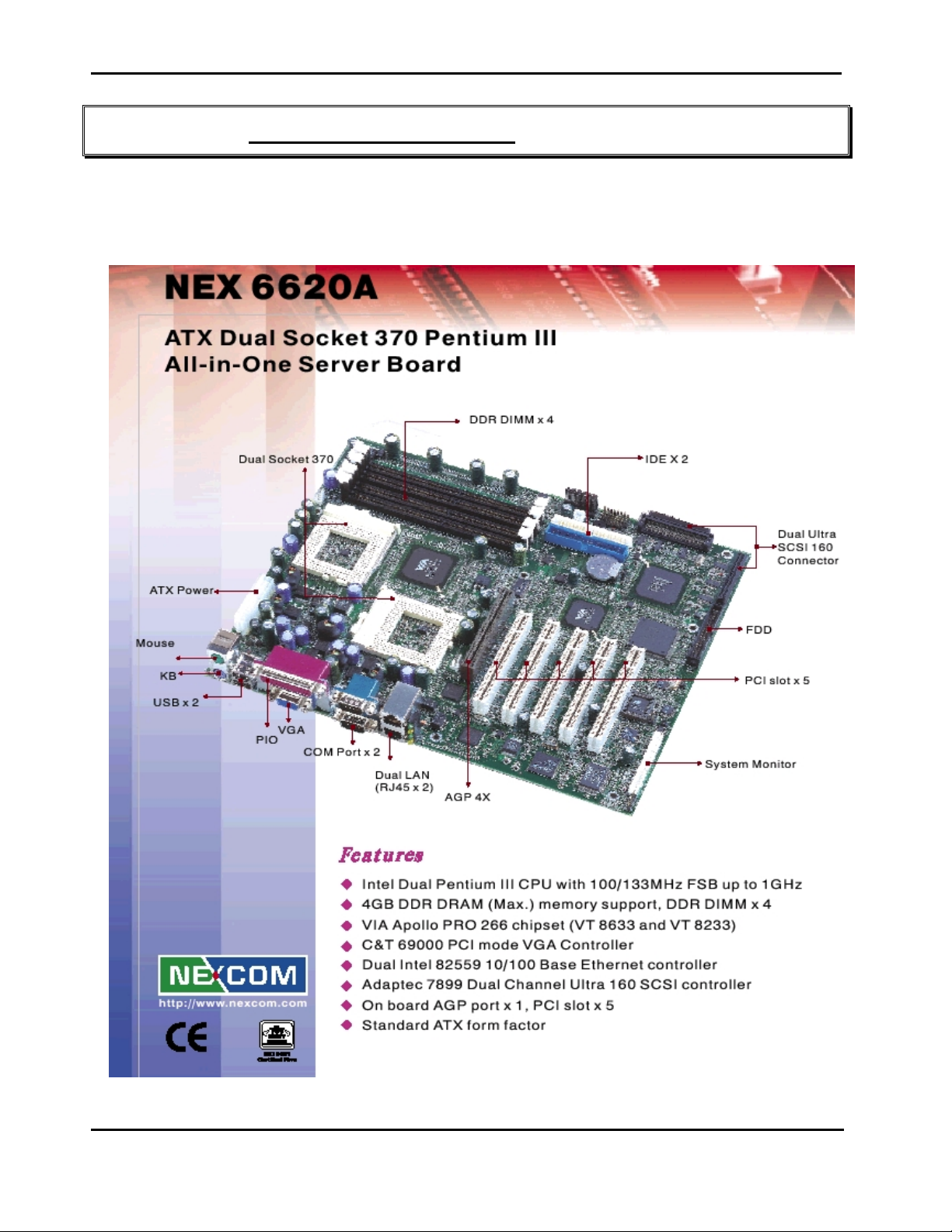
Standard ATX form factor with Dual Pentium III CPU support
AIO board with dual channel Ultra 160 SCSI, dual channel Ethernet and VGA
Next generation server board with industry specification
CPU Support
Intel Dual Pentium III CPU with 128/256K cache on die
Brand New Socket 370 FC-PGA CPU running at 100/133MHz FSB up to 1G+Hz
Support streaming SIMD instruction
Main Memory
Support DDR up to 4GB (Max.)
DDR Socket x 4
ECC support (single bit error correction/Multiple bit errors reporting)
BIOS
Award System BIOS
Plug & Play support
Advanced Power Management support
Advanced Configuration & Power Interface support
Jumper less for CPU FSB
2M bits flash ROM
Chip Set
VIA Apollo PRO 266 Chipset ( VT 8633 and VT8233)
100/133MHz FSB support
PCI V2.2 complied
Intel 21150AB PCI to PCI Bridge
On Board VGA
C&T 69000/69030 PCI mode VGA controller
2MB/4MB SDRAM on die
Driver support:Windows 95/98/2000, Windows NT4.0
On Board LAN
Intel 82559 Single Ethernet controller ×2
10 Base T/100 Base TX support, full duplex
Complied with PCI V2.1, IEEE802.3, IEEE 802.3U
Introduction
1-2
Page 6

NEX 6620A User's Guide Rev. B0 0301
Drivers support:DOS/Windows, Windows 95/98/2000, Windows NT4.0, Netware, SCO Open
Server 5.0
Rear Panel 4 LAN LED (active/link ×2, speed ×2)
On Board SCSI
Adaptec AIC 7899 dual channel Ultra 160 SCSI controller
Brand New Ultra 160 SCSI support
160MB/s (Max.) transfer rate, up to 12 meter cable
Backward compatible with Ultra Wide SCSI, SCSI II, etc.
Drivers support:Windows 95/98/2000, Windows NT4.0, SCO Open Server 5.0
68 pin SCSI connector ×2
On board 4 pin header for LED
On Board I/O
SMsC LPC 47B 272 super I/O
SIO ×2, with 2×16C550 UARTs,
PIO ×1, Bi-directional, EPP/ECP support
Floppy Disk controller: 5.25″ 360KB/1.2MB, 3.5″ 720KB/1.2MB/1.44MB/2.88MB support, 34 pin
connector ×1
On chip enhanced IDE ×2, PIO up to mode 4, DMA master up to mode 2, Ultra DMA/33/66/100
support, total 4 E.IDE Devices support, 40 pin connector ×2
On chip keyboard, mouse controller
On board USB port ×4 ( 2 front 2 rear )
On board buzzer ×1
IrDA connector × 1
On board 2 pin header for I
GPIO (4 in 4 out)
On board 2 pin header for reset SW, 4 pin for speaker, 5 pin for keylock and power LED
2
C
ACPI Function
Soft off
Wake On LAN
Wake On Keyboard
Wake On Ring
RTC alarm wake up
Suspend to Disk
On Board Slot
Total 6 slots, include AGP slot ×1, 32bit/33MHz PCI slot ×5
On Chip RTC
VT8233 Internal High precision real time clock/calendar with battery back up
On Board Solid State Disk Socket
On board reserved power pin for DOM (DiskOnModule):4MB~160MB, etc
System Monitor
Introduction
1-3
Page 7
NEX 6620A User's Guide Rev. B0 0301
Winbond W83782D system monitor controller x 2
8 voltage (For +3.3V, +5V, +12V, −12V, Vtt , Vcore ×2 and V-DIMM 2.5V)
Two Fan speed (For CPU) and Three FAN Speed ( For System )
Two temperature (For CPU)
Drivers support:Windows 95/98, Windows NT4.0/2000
Power Input
ATX power connector ×1, ATX V2.03 specification AUX power connector x 1
Dimensions
Dimensions:305mm(L) x 244mm(W)
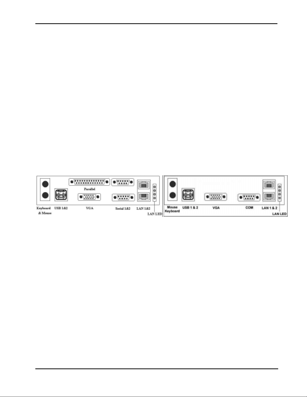
Back Panel
PS2 connector ×2 (for Keyboard/Mouse)
USB port ×2
RJ45 connector ×2 (for LAN)
15 pin D-type connector ×1 (for VGA)
9 pin D-type connector ×2 (for SIO)
25 pin D-type connector ×1 (for PIO)
LAN LED ×4 (active/link ×2, speed ×2)
NEX 6620A / NEX 6620 NEX 6620VL2
Power Requirements ( With Basic configuration running Windows 2000 WIN HCT system stress )
+3.3V:1A
+5V:13A
+12V:0.8A
5VSTBY:0.13A
Environments
Operating temperatures:0°C to 60°C
Storage temperatures:-20°C to 80°C
Relative humidity:10% to 90% (Non-condensing)
Certification
CE approval
FCC Class A
Introduction
1-4
Page 8
NEX 6620A User's Guide Rev. B0 0301
Chapter 2 Switches and Connectors
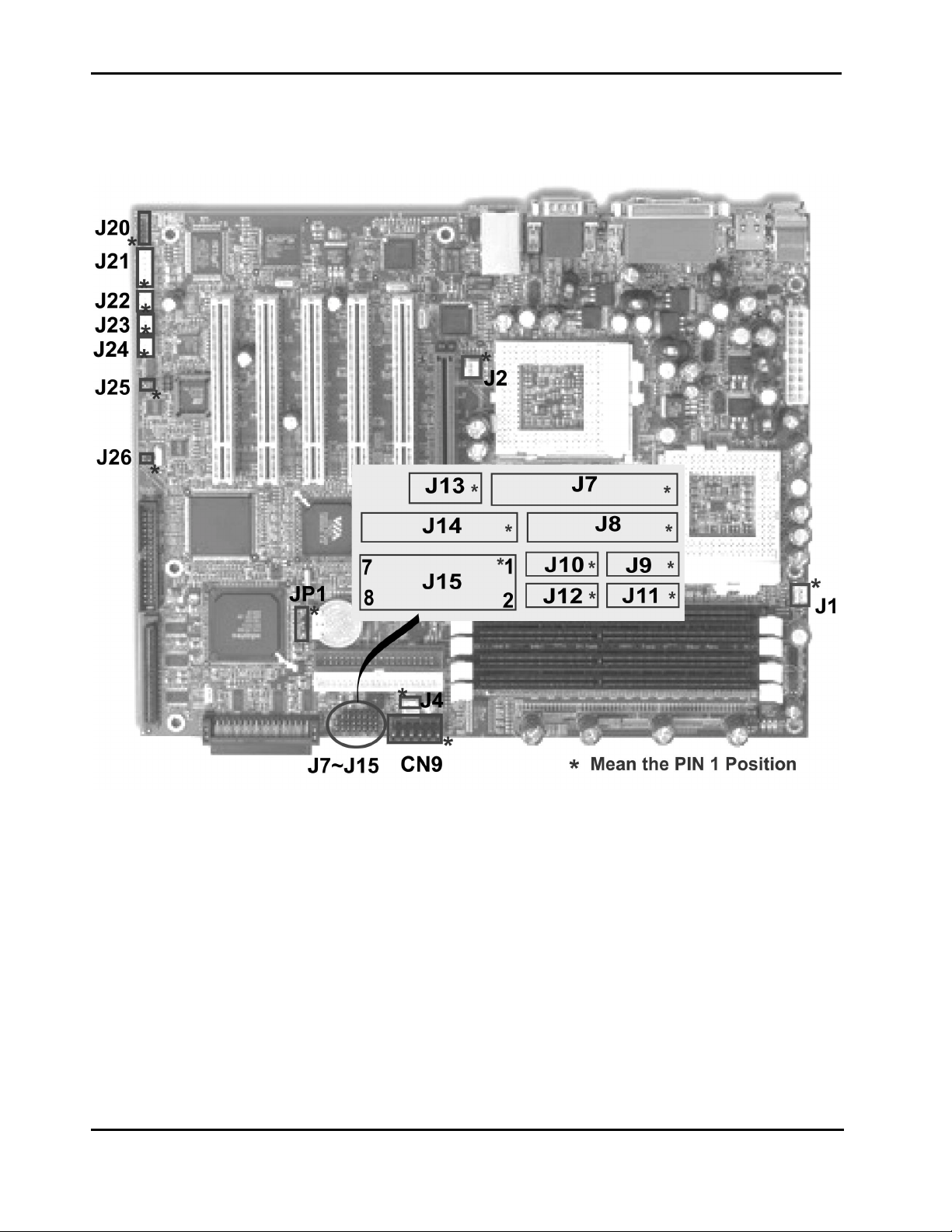
2-1 Main Board Layout
This chapter gives the definitions and shows where to locate the positions of switches and connectors.
Switches and Connectors
2-1
Page 9
NEX 6620A User's Guide Rev. B0 0301
2-2 Connector Pin Define & Jumper Setting
Switches and Connectors
2-2
Page 10
NEX 6620A User's Guide Rev. B0 0301
CN1 : Dual High PC99 Complied PS/2 Connector
Pin No. Description Pin No. Description
K1 Keyboard Data M1 Mouse Data
K2 NC M2 NC
K3 Chassis Ground M3 Chassis Ground
K4 +5V Standby M4 +5V Standby
K5 Keyboard Clock M5 Mouse Clock
K6 NC M6 NC
K7 Chassis Ground M7 Chassis Ground
K8 Chassis Ground M8 Chassis Ground
CN2 : ATX Power Connector
Pin No. Description Pin No. Description
1 +3.3V 11 +3.3V
2 +3.3V 12 -12V
3 Ground 13 Ground
4 +5V 14 PS_ON
5 Ground 15 Ground
6 +5V 16 Ground
7 Ground 17 Ground
8 PWR_OK 18 -5V
9 5V_Standby 19 +5V
10 +12V 20 +5V
CN3 : Dual High PC99 Complied USB Connector for USB1, USB2
Pin No. Description Pin No. Description
1 +5V Standby 2 USB1 Plus
3 USB1 Minus 4 Chassis Ground
5 +5V Standby 6 USB2 Plus
7 USB2 Minus 8 Chassis Ground
Switches and Connectors
2-3
Page 11

NEX 6620A User's Guide Rev. B0 0301
CN4 : Parallel Port & VGA ( DB25 + DB15 Connector )
Pin No. Description Pin No. Description
1 Strobe# 2 Data 0
3 Data 1 4 Data 2
5 Data 3 6 Data 4
7 Data 5 8 Data 6
9 Data 7 10 Acknowledge
11 Busy 12 Paper Empty
13 Printer Select 14 Auto Form Feed#
15 Error# 16 Initialize
17 Printer Select IN# 18 Chassis Ground
19 Chassis Ground 20 Chassis Ground
21 Chassis Ground 22 Chassis Ground
23 Chassis Ground 24 Chassis Ground
25 Chassis Ground 26 Red
27 Green 28 Blue
29 N/A 30 Ground
31 Chassis Ground 32 Chassis Ground
33 Chassis Ground 34 +5V
35 Ground 36 Pull-up
37 DDC Data 38 Horizontal Sync.
39 Vertical Sync. 40 DDC Clock
41 Chassis Ground 42 Chassis Ground
43 Chassis Ground 44 Chassis Ground
Switches and Connectors
2-4
Page 12
NEX 6620A User's Guide Rev. B0 0301
CN5 : Stand-alone VGA DB-15 Connector
Pin No. Description Pin No. Description
1 Red 2 Green
3 Blue 4 N/A
5 Ground 6 Chassis Ground
7 Chassis Ground 8 Chassis Ground
9 +5V 10 Ground
11 Pull-up 12 DDC Data
13 Horizontal Sync. 14 Vertical Sync.
15 DDC Clock 16 Chassis Ground
17 Chassis Ground
CN6 : SIO Dual High DB-9 Connector
Pin No. Description Pin No. Description
1 Data Carrier Detect 2 2 Receive Data 2
3 Transmit Data 2 4 Data Terminal Ready 2
5 Chassis Ground 6 Data set Ready 2
7 Request to Send 2 8 Clear to Send 2
9 Ring Indicator 2 10 Data Carrier Detect 1
11 Receive Data 1 12 Transmit Data 1
13 Data Terminal Ready 1 14 Chassis Ground
15 Data set Ready 1 16 Request to Send 1
17 Clear to Send 1 18 Ring Indicator 1
19 Chassis Ground 20 Chassis Ground
21 Chassis Ground 22 Chassis Ground
CN7 : Stand-alone SIO DB-9 Connector
Pin No. Description Pin No. Description
1 Data Carrier Detect 2 2 Receive Data 2
3 Transmit Data 2 4 Data Terminal Ready 2
5 Chassis Ground 6 Data set Ready 2
7 Request to Send 2 8 Clear to Send 2
9 Ring Indicator 2 10 Chassis Ground
11 Chassis Ground
Switches and Connectors
2-5
Page 13

NEX 6620A User's Guide Rev. B0 0301
CN8: Dual High RJ45 LAN Connector
Pin No. Description Pin No. Description
1 LAN1 TX+ 2 LAN1 TX-
3 LAN1 RX+ 4 TERMPLANE
5 TERMPLANE 6 LAN1 RX-
7 TERMPLANE 8 TERMPLANE
9 LAN2 TX+ 10 LAN2 TX-
11 LAN2 RX+ 12 TERMPLANE
13 TERMPLANE 14 LAN2 RX-
15 TERMPLANE 16 TERMPLANE
17 Chassis Ground 18 Chassis Ground
19 Chassis Ground 20 Chassis Ground
21 Chassis Ground 22 Chassis Ground
23 Chassis Ground 24 Chassis Ground
CN9 : ATX AUX Power Connector
Pin No. Description Pin No. Description
1 Ground 2 Ground
3 Ground 4 +3.3V
5 +3.3V 6 +5V
Switches and Connectors
2-6
Page 14

NEX 6620A User's Guide Rev. B0 0301
CN10, CN11 : IDE Connector
Pin No. Description Pin No. Description
1 Reset # 2 Ground
3 Data 7 4 Data 8
5 Data 6 6 Data 9
7 Data 5 8 Data 10
9 Data 4 10 Data 11
11 Data 3 12 Data 12
13 Data 2 14 Data 13
15 Data 1 16 Data 14
17 Data 0 18 Data 15
19 Ground 20 NC
21 DMA REQ 22 Ground
23 IOW 24 Ground
25 IOR 26 Ground
27 IOCHRDY 28 Pull Down
29 DMA ACK 30 Ground
31 Interrupt 14 32 NC
33 Disk Address 1 34 DMA66 Detect
35 Disk Address 0 36 Disk Address 2
37 HDC CS100 38 HDC CS300
39 HDD Active Led 40 Ground
Switches and Connectors
2-7
Page 15

NEX 6620A User's Guide Rev. B0 0301
CN12, CN14 : SCSI 68 Pin Connector
Pin No. Description Pin No. Description
1 Plus Data12 2 Plus Data13
3 Plus Data14 4 Plus Data15
5 Plus High Byte Parity 6 Plus Data0
7 Plus Data1 8 Plus Data2
9 Plus Data3 10 Plus Data4
11 Plus Data5 12 Plus Data6
13 Plus Data7 14 Plus Low Byte Parity
15 Ground 16 Differential Sense
17 +5V 18 +5V
19 NC 20 Ground
21 Plus Attention 22 Ground
23 Plus Busy 24 Plus Acknowledge
25 Plus Reset 26 Plus Message
27 Plus Select 28 Plus Command / Data
29 Plus Request 30 Plus In / Out
31 Plus Data8 32 Plus Data9
33 Plus Data10 34 Plus Data11
35 Minus Data12 36 Minus Data13
37 Minus Data14 38 Minus Data15
39 Minus High Byte Parity 40 Minus Data0
41 Minus Data1 42 Minus Data2
43 Minus Data3 44 Minus Data4
45 Minus Data5 46 Minus Data6
47 Minus Data7 48 Minus Low Byte Parity
49 Ground 50 Ground
51 +5V 52 +5V
53 NC 54 Ground
55 Minus Attention 56 Ground
57 Minus Busy 58 Minus Acknowledge
59 Minus Reset 60 Minus Message
61 Minus Select 62 Minus Command / Data
63 Minus Request 64 Minus In / Out
65 Minus Data8 66 Minus Data9
67 Minus Data10 68 Minus Data11
Switches and Connectors
2-8
Page 16
NEX 6620A User's Guide Rev. B0 0301
CN13 : Floppy Disk Connector
Pin No. Description Pin No. Description
1 Ground 2 Drive Density Select 0
3 Ground 4 NC
5 Ground 6 Drive Density Select 1
7 Ground 8 Index Pulse Input
9 Ground 10 Motor On 0
11 Ground 12 Drive Select 1
13 Ground 14 Drive Select 0
15 Ground 16 Motor On 1
17 Ground 18 Step Direction
19 Ground 20 Step Pulse
21 Ground 22 Write Disk Data
23 Ground 24 Write Gate
25 Ground 26 Track 0
27 Ground 28 Write Protected
29 NC 30 Read Disk Data
31 Ground 32 Head Select
33 NC 34 Disk Change
J1, J2 : 2.54mm Single Ramp CPU FAN Connector
Pin No. Description Pin No. Description
1 Ground 2 +12V
3 Sense
J4 : 2.54mm 1x2 JST for Disk On Moudle Power Connector
Pin No. Description Pin No. Description
1 Ground 2 +5V
J7 : 1x5 Pin Header for Keylock & Power LED
Pin No. Description Pin No. Description
1 Pull High 2 NC
3 Ground 4 Active Signal
5 Ground
Switches and Connectors
2-9
Page 17

NEX 6620A User's Guide Rev. B0 0301
J8 : 1x4 Pin Header for SCSI LED
Pin No. Description Pin No. Description
1 Pull-up 2 Channel A Active#
3 Pull-up 4 Channel B Active#
J9 : 1x2 Pin Header for ACPI Function S0_LED
Pin No. Description Pin No. Description
1 Ground 2 Pull-up
J10 : 1x2 Pin Header for IDE LED
Pin No. Description Pin No. Description
1 Pull-up 2 Active signal
J11 : 1x2 Pin Header for Intruder SW
Pin No. Description Pin No. Description
1 Active signal 2 Ground
J12 : 1x2 Pin Header for Reset SW
Pin No. Description Pin No. Description
1 Ground 2 Reset
J13 : 1x2 Pin Header for Power Button
Pin No. Description Pin No. Description
1 Active signal 2 Ground
J14 : 1x4 Pin Header for Buzzer / External Speaker ( * Pin 3-4 Short For Internal Buzzer )
Pin No. Description Pin No. Description
1 +5V 2 NC
3 Onboard BZ Active Signal 4 External Speaker Active Signal
Switches and Connectors
2-10
Page 18

NEX 6620A User's Guide Rev. B0 0301
J15 : 2x4 Pin Header for Digital I/O ( Refer to Appendix for Control Table )
Pin No. Description Pin No. Description
1 Digital input 1 2 Digital output 1
3 Digital input 2 4 Digital output 2
5 Digital input 3 6 Digital output 3
7 Digital input 4 8 Digital output 4
J20 : 1x5 Pin Header for External IrDA
Pin No. Description Pin No. Description
1 +5V 2 NC
3 IR Receiver 4 Ground
5 IR Transceiver
J21 : 2.54mm 1x6 JST Connector for USB3, USB4
Pin No. Description PIN No. Description
1 +5V Standby 2
3 USB3 Plus 4
5 USB4 Plus 6
USB3 Minus
USB4 Minus
EMI Ground
J22, J23, J24 : 2.54mm 1x3 JST CASE FAN Connector
Pin No. Description Pin No. Description
1 Sense 2 +12V
3 Ground
J25 : 1x2 Pin Header for BIOS Hardware Protection
Pin No. Description Pin No. Description
1 Ground 2 Active signal
2
J26 : 1x2 Pin Header for I
C (SMBUS)
Pin No. Description Pin No. Description
1 Data 2 Clock
Switches and Connectors
2-11
Page 19

NEX 6620A User's Guide Rev. B0 0301
JP1 : 1x3 Jumper for On Board RTC
Pin No. Description
*1, 2 Short
2, 3 Short Clear CMOS
( * = Default )
Operation Mode
.
Switches and Connectors
2-12
Page 20
NEX 6620A User's Guide Rev. B0 0301
Chapter 3 Capability Expanding
This chapter explains how you can expand capability of your CPU board in such aspects as s ystem mem ory
and CPU.
3-1 System Memory
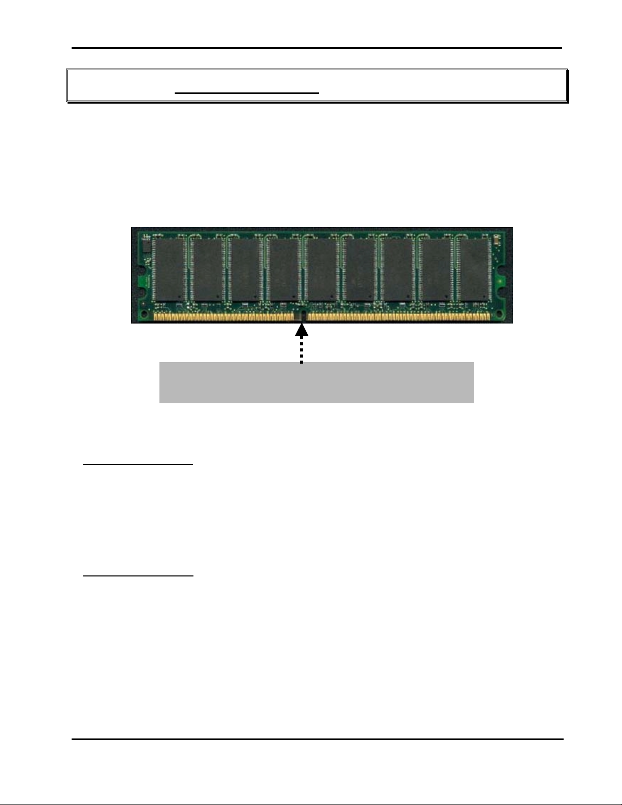
NEX 6620A series can install to 4 Double Data Memory Module (DDR) DIMM sockets and supports the
maximum memory size up to 4GB. The architecture to provide the best choice for performance vs. stability
184 pins DDR SDRAM DIMM Module.
Please check the Position before Install the Module.
Installing DDR DIMM
To install the DDR DIMM’s, first m ak e sure the two handles of the DIMM s ock et are in the “open” pos ition,
i.e. the handles stay outward. Slowly slide the DIMM modules along the plastic guides in the both ends of
the socket. Then press the DIMM m odule down right into the sock et, until a click is heard. That m eans
the two handles automatically locked the memory modules into the right position of the DIMM socket
Remove DDR DIMMs
To take away the memory module, just push the both handles outward, the memory module will be ejected
by the mechanism in the socket.
Capability Expanding
3-1
Page 21

NEX 6620A User's Guide Rev. B0 0301
This page is intentionally left blank.
Capability Expanding
3-2
Page 22

NEX 6620A User's Guide Rev. B0 0301
Chapter 4 AWARD BIOS Setup
Award's BIOS ROM has a built-in Setup program that allows users to modify the basic system configuration.
This type of information is stored in battery-backed RAM (CMOS RAM) so that it retains the Setup
information when the power is turned off.
The Chapter show the currently BIOS setup picture is for reference only, which may change by the
BIOS modification in the future. Any Major updated items or re-version, user can download from
NEXCOM web site http://www.nexcom.com.tw
Customer Service people for help http://www.nexcom.com.tw/contact/contact.htm
4-1 BIOS Setup
Entering Setup
Power on the computer and press <Del> im mediately will allow you to enter Setup. The other way to
enter Setup is to power on the computer, when the below message appears briefly at the bottom of the
screen during the POST (Power On Self Test), press <Del> key or simultaneously press <Ctrl>, <Alt>,
and <Esc> keys.
,or any unclear message, can contact NEXCOM
TO ENTER SETUP BEFORE BOOT
PRESS <CTRL-ALT-ESC> OR <DEL> KEY
If the message disappears befor e you respond and you still wish to enter Setup, restart the system to try
again by turning it OFF then ON or pressing the "RESET" button on the system case. You may also
restart by simultaneously pressing <Ctrl>, <Alt>, and <Delete> keys. If you do not press the keys at the
correct time and the system does not boot, an error mes s age will be displayed and you will again be asked
to,
PRESS <F1> TO CONTINUE,
<CTRL-ALT-ESC> OR <DEL> TO ENTER SETUP
BIOS Setup
4-1
Page 23
NEX 6620A User's Guide Rev. B0 0301
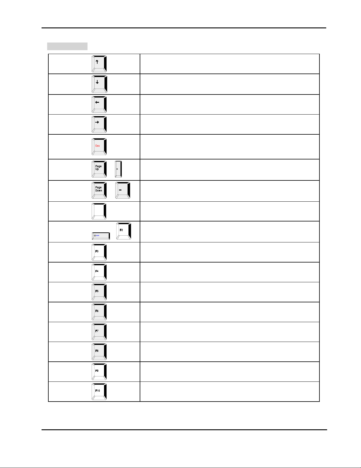
Control Keys
Up arrow
Down arrow
Left arrow
Right arrow
Esc key
PgUp / “+” key
PgDn / “−“ key
F1 key
(Shift)F2 key
/
/
F1
( )
Move to previous item
Move to next item
Move to the item in the left hand
Move to the item in the right hand
Main Menu -- Quit and not save changes into CMOS
Status Page Setup Menu and Option Page Setup Menu -- Exit current page and
return to Main Menu
Increase the numeric val ue or make changes
Decrease the numeric value or make changes
General help, only for Status P age S etup Menu and Option Page Setup Menu
Change color from total 16 colors . F2 to s elect color f orward, (Shift) F2 to s elect
color backward
.
F3 key
F4 key
F5 key
F6 key
F7 key
F8 key
F9 key
F10 key
Reserved
Reserved
Restore the previous CMOS value from CMOS, only for Option Page Setup Menu
Load the default CMOS value from BIOS default tabl e, only f or Option P age Set up
Menu
Load the Setup default , only for Option Page Setup Menu
Reserved
Reserved
Save all the CMOS changes, only for Main Menu
Table 4-1 Control Keys
BIOS Setup
4-2
Page 24
NEX 6620A User's Guide Rev. B0 0301
Getting Help
Main Menu
The on-line description of the highlighted setup function is displayed at the bottom of the screen.
Sub-Menu
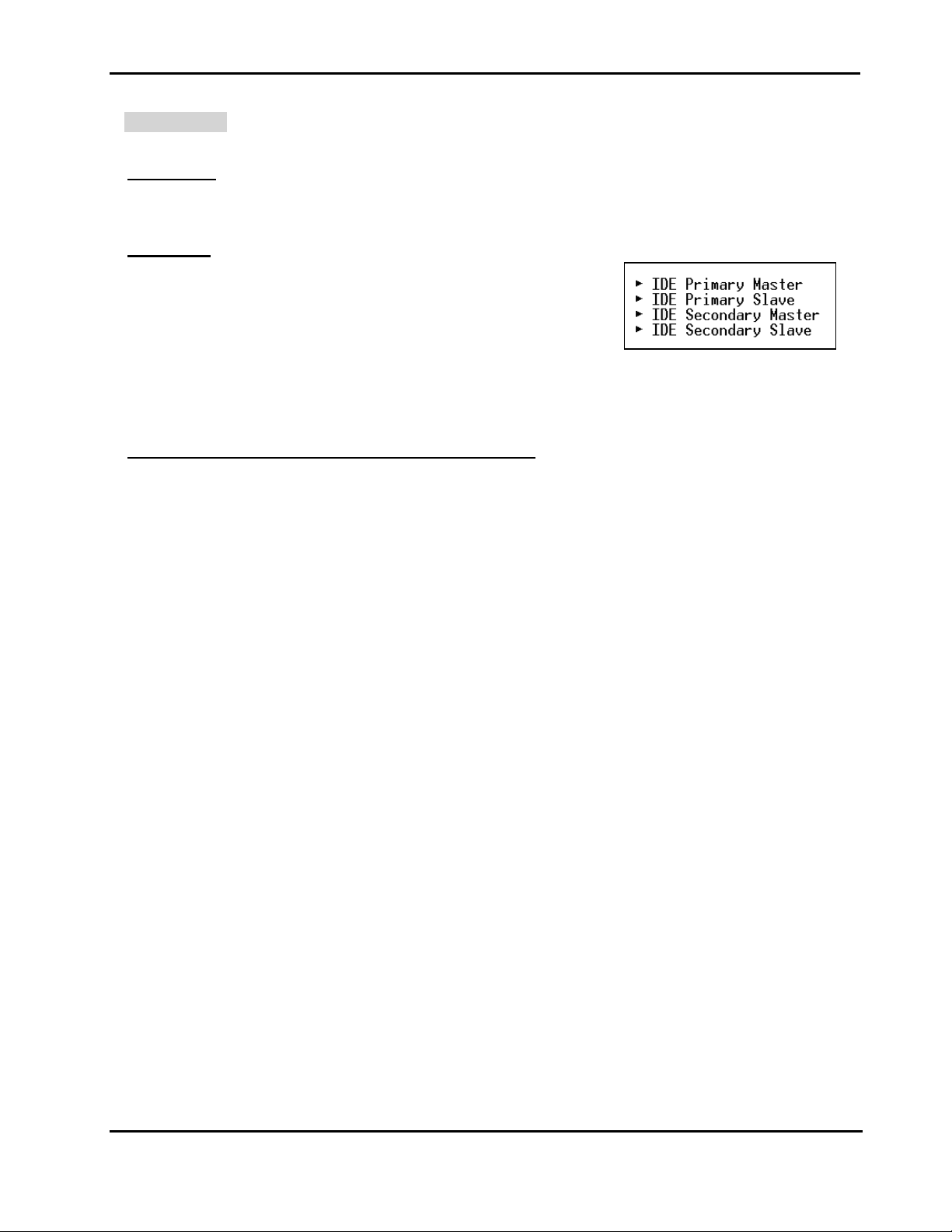
If you find a right pointer symbol appears to the left of certain fields (as
shown in the right view), that means a sub-m enu containing additional
op-tions for the field can be launched from this field.
To enter the sub-menu, highlight the field and press <Enter>. Then
you can use control keys to move between and change the settings of the sub-menu.
To return to the main menu, press <Esc>.
Status Page Setup Menu/Option Page Setup Menu
Press <F1> to pop up a small help window that describes the appropriate keys to use and the poss ible
selections for the highlighted item. To exit the Help Window press <F1> or <Esc>.
BIOS Setup
4-3
Page 25
NEX 6620A User's Guide Rev. B0 0301
The Main Menu
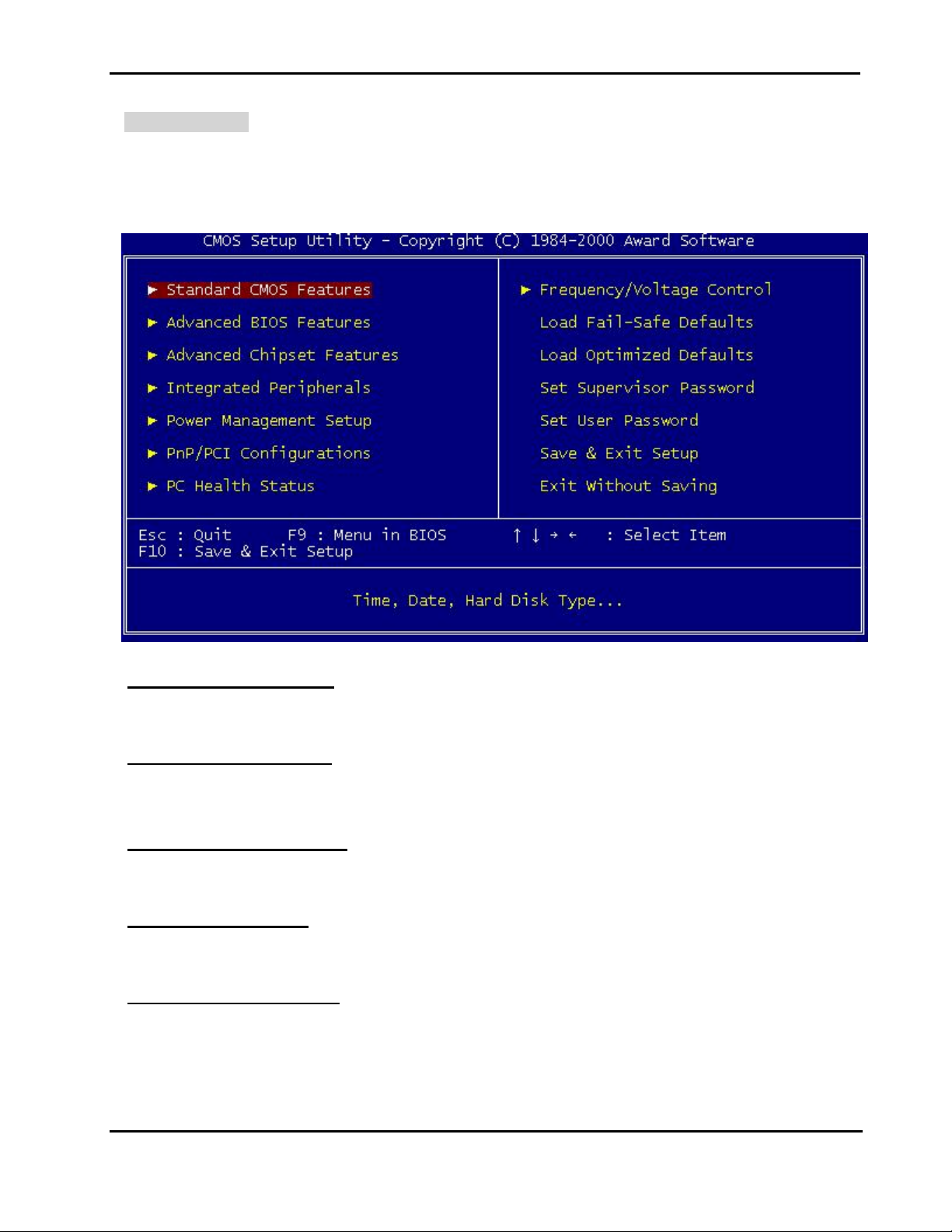
Once you enter Award BIOS CMOS Setup Utility, the Main Menu (Figure 1) will appear on the screen.
The Main Menu allows you to select from ten setup func tions and two exit choices. Use arrow keys to
select among the items and press <Enter> to accept or enter the sub-menu.
Standard CMOS Features
Use this menu for basic system configuration.
Advanced BIOS Features
Use this menu to set the Advanced Features available on your system.
Advanced Chipset features
Use this menu to change the values in the chipset registers and optimize your system's performance.
Integrated Peripherals
Use this menu to specify your settings for integrated peripherals.
Power Management setup
Use this menu to specify your settings for power management
BIOS Setup
4-4
Page 26

NEX 6620A User's Guide Rev. B0 0301
PNP/PCI Configuration
This entry appears if your system supports PnP / PCI.
PC health Status
Display CPU/System Temperature, Fan speed.
Frequency/Voltage Control
Use this menu to specify your settings for frequency/voltage control.
Load Fail-Safe Defaults
Use this menu to load the BIOS default values for the minimal/stable performance for your system to
operate.
Load Optimized Defaults
Use this menu to load the BIOS default values that are factory settings for optimal perf ormance system
operations. While Award has designed the custom BIO S to maximize performance, the f actory has the
right to change these defaults to meet their needs.
Set User Password
Change, set, or disable password of supervis or or user. It allows you to limit access to the system and
Setup, or just to Setup.
Save & Exit Setup
Save CMOS value changes to CMOS and exit setup.
Exit Without Saving
Abandon all CMOS value changes and exit setup.
BIOS Setup
4-5
Page 27
NEX 6620A User's Guide Rev. B0 0301
Standard CMOS Features
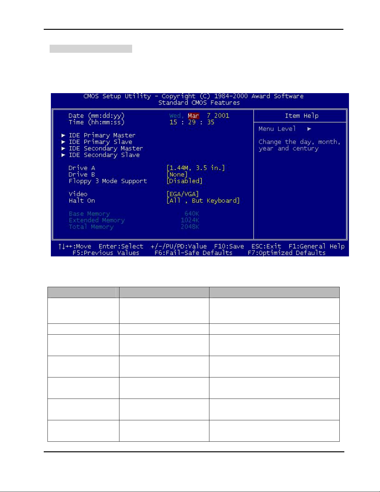
The items in Standard CMOS Setup Menu ar e divided into 10 categories. Each category includes no,
one or more than one setup item s. Us e the arrow k eys to highlight the item and then us e the <PgUp> or
<PgDn> keys to select the value you want in each item.
Main Menu Selections
Item Options Description
Set the system date. Note that the ‘Day’
Date Month DD YYYY
automatically changes when you set the
date
Time HH : MM : SS Set the system time
IDE Primary Master
IDE Primary Slave
IDE Secondary Master
IDE Secondary Master
Drive A
Drive B
Options are in its sub menu
(Described in Table 4-3)
Options are in its sub menu
(Described in Table 4-3)
Options are in its sub menu
(Described in Table 4-3)
Options are in its sub menu
(Described in Table 4-3)
None
360K, 5.25 in
Press <Enter> to enter the sub menu of
detailed options
Press <Enter> to enter the sub menu of
detailed options
Press <Enter> to enter the sub menu of
detailed options
Press <Enter> to enter the sub menu of
detailed options
Select the type of floppy disk drive installed
in your system
BIOS Setup
4-6
Page 28

NEX 6620A User's Guide Rev. B0 0301
1.2M, 5.25 in
720K, 3.5 in
1.44M, 3.5 in
2.88M, 3.5 in
Disabled
Drive A
Floppy 3 Mode Support
Drive B
Both
3 Mode floppy disk drives (FDD) are 3 1/2”
drives used in Japanese computer
systems. If you need to access data
stored in this kind of floppy, you must
select this mode, and of course you must
have a 3 Mode floppy drive.
EGA/VGA
CGA 40
Video
Select the default video device
CGA 80
MONO
All Errors
Halt On
No Errors
All, but Keyboard
All, but Diskette
Select the situation in which you want the
BIOS to stop the POST process and notify
you
All, but Disk/Key
Base Memory N/A Displays the amount of conventional
memory detected during boot up
Extended Memory N/A Displays the amount of extended memory
detected during boot up
Total Memory N/A Displays the total memory available in the
system
Table 4-2 Main Menu Selections
BIOS Setup
4-7
Page 29

NEX 6620A User's Guide Rev. B0 0301
IDE Adapters
The IDE adapters control the hard disk drive. Use a separ ate sub menu to configure each hard dis k dr ive.
Use the legend keys to navigate through this menu and exit to the m ain m enu. Use Table 3 to conf igure
the hard disk.
Item Options Description
IDE HDD Autodetection
Press Enter Press Enter to auto-detect the HDD on this
channel. If detection is successful, it fills the
remaining fields on this menu.
IDE Primary Master None
Auto
Manual
Selecting ‘manual’ lets you set the remaining
fields on this screen. Selects the type of f ixed
disk. "User Type" will let you select the
number of cylinders, heads, etc. Note:
PRECOMP=65535 means NONE !
Capacity Auto Display your disk drive
size
Disk drive capacity (Approxim ated). Note that
this size is usually slightly greater than the size
of a formatted disk given by a disk checking
program.
Access Mode Normal
Choose the access mode for this hard disk
LBA
Large
Auto
The following options are selectable only if the ‘IDE Primary Master’ item is set to ‘Manual’
Cylinder Min = 0
Set the number of cylinders for this hard disk.
Max = 65535
Head Min = 0
Set the number of read/write heads
Max = 255
Precomp Min = 0
Max = 65535
**** Warning: Setting a value of 65535 m eans
no hard disk
Landing zone Min = 0
Max = 65535
Sector Min = 0
Max = 255
BIOS Setup
****
Number of sectors per track
Table 4-3 Hard disk selections
4-8
Page 30
NEX 6620A User's Guide Rev. B0 0301
Advanced BIOS Features Setup Menu
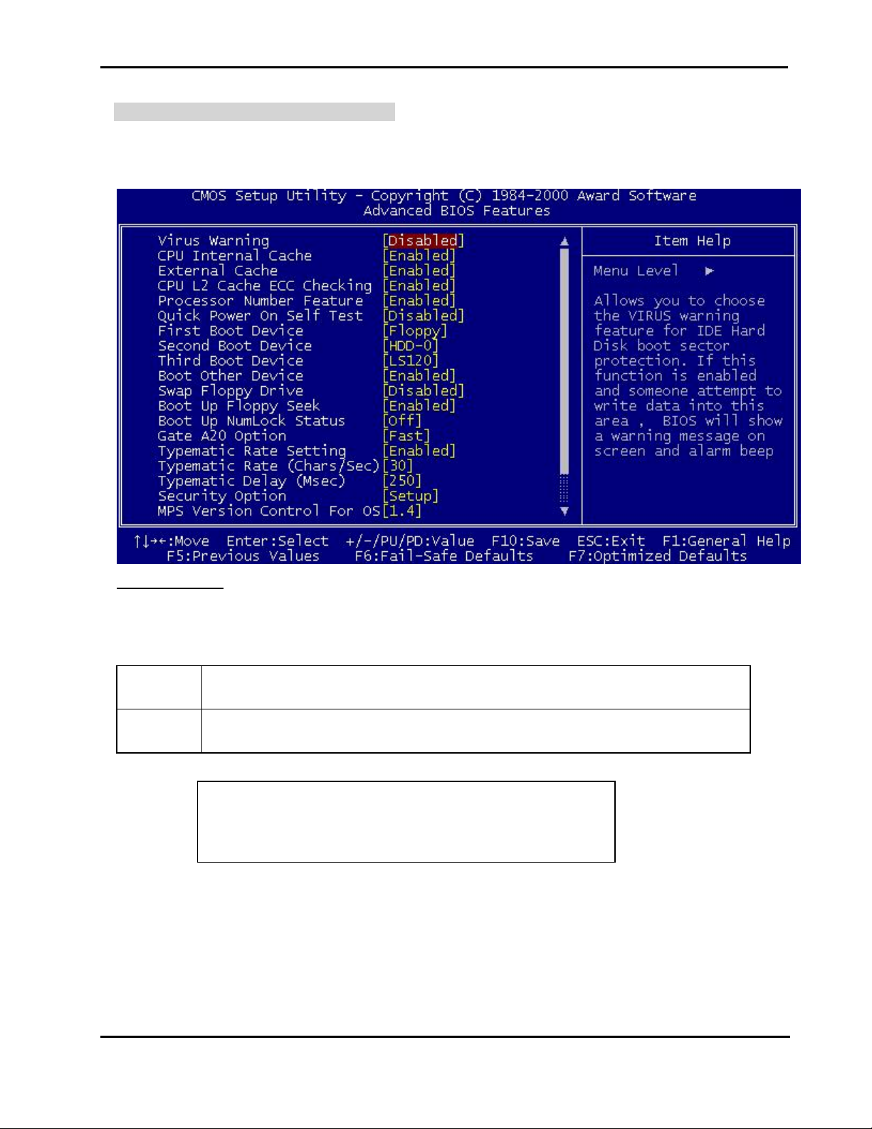
This section allows you to configure your system for bas ic operation. You have the opportunity to select
the system’s default speed, boot-up sequence, keyboard operation, shadowing and security.
Virus Warning
Allows you to choose the VIRUS Warning feature for IDE Hard Disk boot sector protection. If this
function is enabled and someone attempt to write data into this area, BIOS will show a warning message
on screen and alarm beep.
Enabled Activates automatically when the system boots up causing a warning message to
appear when anything attempts to access the boot sector or hard disk partition table.
Disabled No warning message will appear when anything attempts to access the boot sector
or hard disk partition table.
! WARNING!
Disk boot sector is to be modified
Type "Y" to accept write or "N" to abort write
Award Software, Inc.
Note: This function is available only for DOS and other OSes that do not trap INT13.
BIOS Setup
4-9
Page 31

NEX 6620A User's Guide Rev. B0 0301
CPU Internal Cache/External Cache
These two categories speed up memory access. However, it depends on CPU/chipset design. The
default value is Enable. If your CPU without Internal Cache then this item “CPU Internal Cache” will not
be show.
The Choice: Enabled, Disabled
CPU L2 Cache ECC Checking
This category could turn on the ECC of Pentium III L2 Cache or just disable it.
The Choice: Enabled/Disabled
Processor Number Feature
Intel included a serial number in their Pentium III processors as a unique system identifier. For privacy
reasons, you can disable this setting to prevent the release of this identifier.
The Choice: Enabled, Disabled
Quick Power On Self Test
This category speeds up Power On Self Test (POST) after you power on the com puter. If it is set to
Enable, BIOS will shorten or skip some check items during POST.
The Choice: Enabled, Disabled
First / Second / Third Boot Device
The BIOS attempts to load the operating system from the devices in the sequence selected in these items.
The Choice: Floppy, LS120, HDD-0, SCSI, CDROM, HDD-1, Hdd-2, HDD-3, ZIP100, USB-FDD, USB-ZIP,
USB-CDROM, USB-HDD, Disabled.
Boot Other Device
If all the selected boot devices failed to boot, s elect Enabled the BIO S will try to boot from the other boot
devices (in a predefined sequence) which ar e present but not selected as boot devices in the setup ( and
hence have not yet been tried for booting). If select Disabled, that may be present but not selected as boot
devices in setup.
Swap Floppy drive
If the system has two floppy drives, you can swap the logical drive name assignments.
The Choice: Enabled, Disabled.
Boot Up Floppy Seek
Seeks disk drives during boot up. Disabling speeds boot up.
The Choice: Enabled, Disabled.
Boot Up NumLock Status
Select power on state for NumLock.
The Choice: On/Off.
BIOS Setup
4-10
Page 32

NEX 6620A User's Guide Rev. B0 0301
Gate A20 Option
Select if chipset or keyboard controller should control GateA20.
Normal A pin in the keyboard contr oller controls GateA20
Fast Lets chipset control Gate A20
Typematic Rate Setting
Key strokes repeat at a rate determined by the keyboard controller. When enabled, the typematic rate
and typematic delay can be selected.
The Choice: Enabled, Disabled.
Typematic Rate (Chars/Sec)
Sets the number of times a second to repeat a key stroke when you hold the key down.
The Choice: 6, 8, 10, 12, 15, 20, 24, 30
Typematic Delay (Msec)
Sets the delay time after the key is held down before it begins to repeat the keystroke.
The Choice: 250, 500, 750, 1000.
Security Option
Select whether the password is required every time the system boots or only when you enter setup.
System T he system will not boot and access to Setup will be denied if
the correct password is not entered at the prompt .
Setup The system will boot, but access to Set up will be denied if the
correct password is not entered at the prompt.
Note: To disable security, select PASSWORD SETTING at Main Menu and then you will be asked to enter
password. Do not type anything and just press <Enter>, it will disable security. Once the security
is disabled, the system will boot and you can enter Setup freely.
MPS Version control For OS
This field specifies the version of MPS used by the motherboard.
The Choice: 1.1, 1.4
OS Select for DRAM > 64MB
Select the operating system that is running with greater than 64MB of RAM on the system.
The Choice: Non-OS2, OS2
BIOS Setup
4-11
Page 33

NEX 6620A User's Guide Rev. B0 0301
HDD S.M.A.R.T. Capability
S.M.A.R.T. (Self-Monitoring, Analysis and Reporting Technology) is a technology developed to manage
the reliability of the hard disk by predicting future device failur es. The hard disk needs to be S.M.A.R.T.
capable. The settings for this option are Disabled or Enabled.
* Note: S.M.A.R.T. cannot predict all future device failures. S.M.A.R.T. should be used as a warning tool,
not as a tool to predict the device reliability.
The Choice: Enabled/Disabled.
Video BIOS Shadow
It determines whether video BIOS will be copied to RAM, however, it is optional from chipset design.
Video Shadow will increase the video speed.
Enabled Video shadow is enabled
Disabled Video shadow is disabled
BIOS Setup
4-12
Page 34

NEX 6620A User's Guide Rev. B0 0301
Advanced Chipset Features Setup Menu
Since the features in this section are related to the chipset in the CPU board and all are optimized, you are
not recommended to change the default settings in the setup table, unless you know very detailed of the
chipset features.
This section allows you to configure the system based on the specific features of the installed chipset.
This chipset manages bus speeds and access to system memory resources, such as DRAM and the
external cache. It also coordinates comm unications between the conventional ISA bus and the PCI bus.
It must be stated that these items should never need to be altered. The default settings have been
chosen because they provide the best operating conditions for your system. The only time you might
consider making any changes would be if you discovered that data was being lost while using your system.
The first chipset settings deal with CPU access to dynamic random ac c ess memory (DRAM). T he def ault
timings have been carefully chosen and should only be altered if data is being lost. Such a scenario
might well occur if your system had mixed speed DRAM chips installed so that greater delays may be
required to preserve the integrity of the data held in the slower memory chips.
►► DRAM Clock/Drive Control
Press <Enter> to enter the sub-menu, and you will see a sub-menu.
Current FSB Frequence
Displays current Host Clock frequency.
BIOS Setup
4-13
Page 35

NEX 6620A User's Guide Rev. B0 0301
DRAM Clock
The chipset supports synchronous and asynchronous mode between host clock and DRAM clock
frequency.
Host CLK The DRAM clock will be equal to the Host Clock.
HCLK-33M The DRAM clock will be equal to the Host Clock
minus 33MHz. For example, if the Host Clock is
133MHz, the DRAM clock will be 100MHz.
HCLK+33M The DRAM clock will be equal to Host Clock plus
33MHz. For example, if the Host Clock is 100MHz,
the DRAM clock will be 133MHz.
By SPD BIOS automatically determine the DRAM clock
frequency by SPD IC on the DRAM card.
DRAM Timing
Selects whether the SPD IC on the DRAM card or Manual controls DRAM timing.
Selecting Manual allows you to control SDRAM Cycle Length and Bank Interleave by yourself.
It is strongly suggested to select By SPD to avoid causing any system error.
The Choice: Manual, By SPD.
SDRAM Cycle Length
Controls the time delay (in clock cycles) before SDRAM starts a read command after receiving it.
The Choice: 3, 2.5, 2.
Bank Interleave
Enables or disables bank interleave feature.
The Choice: Disabled, 2 Bank, 4 Bank.
►► AGP & P2P Bridge Control
Press <Enter> to enter the sub-menu, and you will see a sub-menu.
AGP Aperture Size
Select the size of Accelerated Graphics Port (AGP) aperture. The aperture is a portion of the PCI
memory address range dedicated for graphics memory address space. Host cycles that hit the
aperture range are forwarded to the AGP without any translation.
BIOS Setup
4-14
Page 36

NEX 6620A User's Guide Rev. B0 0301
The Choice: 4M, 8M, 16M, 32M, 64M, 128M, 256M.
AGP Mode
The Choice: 1X, 2X, 4X.
AGP Driving Control
This filed is used to adj ust the AGP driving f orce. Selecting Manual allows you to type an AGP driving
force in AGP Driving Value
It is strongly suggested to select Auto to avoid causing any system error.
.
AGP Driving Value
Specifies the AGP driving force.
AGP Fast Write
Enable this function only if the AGP Card supports Fast Write Function. Enable this function can
increase AGP performance.
The Choice: Enabled, Disabled.
AGP Master 1 WS Write
AGP Master One Wait State Write control.
The Choice: Enabled, Disabled.
AGP Master 1 WS Read
AGP Master One Wait State Read control.
The Choice: Enabled, Disabled.
► CPU & PCI Bus Control
Press <Enter> to enter the sub-menu, and you will see a sub-menu.
CPU to PCI Write Buffer
Enables or disables CPU to PCI Post-Write function.
The Choice: Enabled, Disabled.
PCI Delay Transaction
The chipset has an embedded 32- bit posted write buffer to support delay transac tions cycles. Selec t
Enabled to support compliance with PCI specification version 2.1.
The Choice: Enabled, Disabled.
Memory Hole
BIOS Setup
4-15
Page 37

NEX 6620A User's Guide Rev. B0 0301
In order to improve perfor mance, ce rtain space in m emory can be res erved for ISA cards. This m emo ry
must be mapped into the memory space below 16 MB.
The Choice: Disabled, 15M - 16M.
System BIOS Cacheable
Selecting Enabled allows caching of the system BIOS ROM at F0000h-FFFFFh, resulting in better system
performance. However, if any program writes to this memory area, a system error may result.
The Choice: Enabled, Disabled.
Memory Parity/ECC Check
Select Parity/ECC (error-correcting code) according to the type of installed DRAM.
The Choice: Enabled, Disabled.
BIOS Setup
4-16
Page 38
NEX 6620A User's Guide Rev. B0 0301
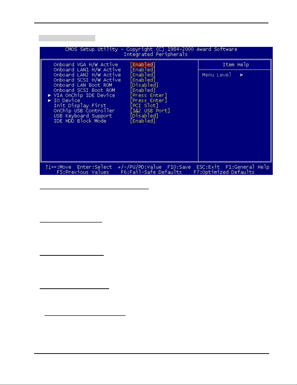
Integrated Peripherals
Onboard VGA/LAN1/LAN2/SCSI H/W Active
Select the enabled if there is a H/W active installed on the system board and you wish to use it.
The Choice: Enabled, Disabled.
Onboard LAN Boot ROM
Select enabled if you wish to run the LAN Boot ROM as boot–up your computer.
The Choice: Disabled, LAN1, LAN2.
Onboard SCSI Boot ROM
Select enabled if you wish to run the SCSI Boot ROM as boot–up your computer.
The Choice: Enabled, Disabled.
► VIA OnChip IDE Device
Press <Enter> to enter the sub-menu, and you will see a sub-menu.
OnChip IDE Channel0/Channel1
The chipset contains a PCI IDE interface with suppor t for two IDE channels. Select Enabled to activate
this IDE interface. Select Disabled to deactivate this interface
The Choice: Enabled, Disabled.
BIOS Setup
4-17
Page 39

NEX 6620A User's Guide Rev. B0 0301
IDE Prefetch Mode
The onboard IDE drive interfaces supports prefetching, for faster drive accesses. Set to Disabled if
your primary and/or econdary add-in IDE interface does not support prefetching.
The Choice: Enabled, Disabled.
Primary/Secondary Master/Slave PIO
The four IDE PIO (Program med Input/Output) fields let you set a PIO m ode (0-4) for each of the four
IDE devices that the onboard IDE interface supports . Modes 0 through 4 provide succes s ively increased
performance. In Auto mode, the system automatically determines the best mode for each device.
The Choice: Auto, Mode 0, Mode 1, Mode 2, Mode 3 and Mode 4.
Primary/Secondary Master/Slave UDMA
Ultra DMA implementation is possible only if your IDE hard drive supports it and the operating
environment includes a DMA driver (W indows 95 OSR2 or a thir d-party IDE bus master driver). If your
hard drive and your system software both support Ultra DMA, select Auto to enable BIOS support.
The Choice: Auto, Disabled.
► IO Device
Press <Enter> to enter the sub-menu, and you will see a sub-menu.
POWER ON Function
This item allows you the select power on event.
The Choice: Any Key, Button Only, Keyboard 98.
Onboard FDC Controller
Select Enabled if your system has a floppy disk controller (F DC) installed on the system board and you
wish to use it. If you install and-in FDC or the system has no floppy drive, select Disabled in this field.
The Choice: Enabled, Disabled.
Onboard Serial Port 1/Port 2
Select an address and corresponding interrupt for the first and second serial ports.
The Choice: 3F8/IRQ4, 2F8/IRQ3, 3E8/IRQ4, 2E8/IRQ3, Disabled, Auto.
UART Mode Select
This item allows you to select second serial port mode.
The Choice: Normal, IrDA, ASKIR.
UR2 Duplex Mode
This item allows you to select the IR half/full duplex function.
BIOS Setup
4-18
Page 40

NEX 6620A User's Guide Rev. B0 0301
The Choice: Half, Full.
TxD, RxD Polarity Active
This item allows you to determine the active of IR. TxD, RxD signal.
The Choice: “Hi, Hi”, “Lo, Lo”, “Lo, Hi”, “Hi, Lo”.
Onboard Parallel Port
This item allows you to determine access On-Board parallel port controller with which I/O address.
The Choice: 378/IRQ7, 278/IRQ5, 3BC/IRQ7, Disabled.
Parallel Port Mode
Select an operating mode for the O n-Board parallel (printer) port. Select Normal, Compatible, or SPP
unless you are certain your hardware and software both support one of the other available modes.
The Choice: SPP, ECP, PRINTER, EPP1.9+SPP, EPP1.9+ECP, EPP1.7+SPP, EPP1.7+ECP.
ECP Mode Use DMA
Select a DMA channel for the parallel port for use during ECP mode.
The Choice: 3, 1.
Init Display First
This item allows you to decide to active whether PCI Slot, AGP, or on-board VGA first.
The Choice: PCI Slot, Onboard, AGP.
USB Controller
The item specifies which USB (Universal Serial Bus) Port is enabled.
The Choice: All Disabled, All Enabled, 1&2 USB Port, 2&3 USB Port, 1&3 USB Port, 1 USB Port, 2 USB
Port, 3 USB Port.
USB Keyboard Support
Select Enabled if your system contains a Universal Serial Bus (USB) controller and you have a USB
keyboard.
The Choice: Enabled, Disabled.
IDE HDD Block Mode
Block mode is als o called block transfer, multiple commands, or multiple sector read/write. If your IDE
hard drive supports block mode (most new drives do), select Enabled for automatic detection of the
optimal number of block read/writes per sector the drive can support.
The Choice: Enabled, Disabled.
BIOS Setup
4-19
Page 41
NEX 6620A User's Guide Rev. B0 0301
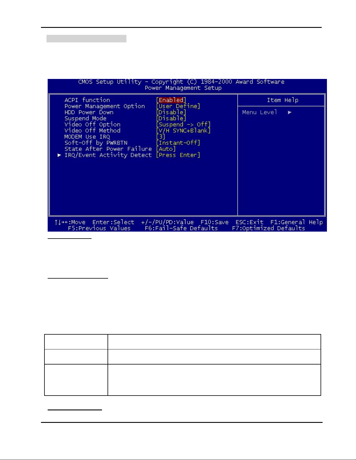
Power Management Setup
The Power Management Setup allows you to configure you system to m ost eff ectively save energy while
operating in a manner consistent with your own style of computer use.
ACPI Function
This item allows you to enable/disable the Advanced Configuration and Power Management (ACPI).
The Choice: Enabled, Disabled.
Power Management
This category allows you to select the type (or degree) of power saving and is directly related to the
following modes:
1. HDD Power Down
2. Suspend Mode
There are four selections for Power Management, three of which have fixed mode settings.
Min. Power Saving Minimum power management. Suspend Mode = 1 hr.
Max. Power Saving Maximum power management. Suspend Mode = 1 min.
User Defined Allows you to set each mode individually. When not disabled, each of the
ranges from 1 min. to 1 hr. except for HDD Power Down which ranges from 1
min. to 15 min. and disable.
HDD Power Down
BIOS Setup
4-20
Page 42

NEX 6620A User's Guide Rev. B0 0301
When enabled and after the set time of system inactivity, the hard disk drive will be powered down while all
other devices remain active.
The Choice: ranges from 1 min. to 15 min. and Disable.
Suspend Mode
When enabled and after the set time of system inactivity, all devices except the CPU will be shut off.
The Choice: ranges from 1 min. to 1 hr. and Disable.
Video Off Option
This determines the manner in which the monitor is blanked.
The Choice: Always On, Suspend -> Off.
Video Off Method
This determines the manner in which the monitor is blanked.
V/H SYNC+Blank This selection will cause the system to turn off the vertical and horizontal
synchronization ports and write blanks to the video buffer.
Blank Screen This option only writes blanks to the video buffer.
DPMS Support Initial display power management signaling.
MODEM Use IRQ
This determines the IRQ in which the MODEM can use.
The Choice: 3, 4, 5, 7, 9, 10, 11, NA.
Soft-Off by PWR-BTTN
Pressing the power button for more than 4 s econds f orc es the s ystem to enter the Sof t-Of f state when the
system has “hung.”
The Choice: Delay 4 Sec, Instant-Off.
► IRQ/Event Activity Detect
Press <Enter> to enter the sub-menu, and you will see a sub-menu.
USB Resume / VGA / LPT & COM / HDD & FDD / PCI Master
These items s pecify whether the system will be awakened from power saving modes when activity or
input signal of the specified hardware peripheral or component is detected.
Wake Up On LAN
The Choice: Enabled, Disabled.
PowerOn by PCI Card
BIOS Setup
4-21
Page 43

NEX 6620A User's Guide Rev. B0 0301
When enabled, you can “wake-up” your system using a PCI rev.2.2 card, when a “PME” event occurring.
The Choice: Enabled, Disabled.
Modem Ring Resume
An input signal on the serial Ring Indicator(RI) line (in other words, an incom ing call on the modem)
awakens the system from a soft off state..
The Choice: Enabled, Disabled.
RTC Alarm Resume
This is to enable or disable the feature of booting up the system on a scheduled time/date.
The Choice: Enabled, Disabled.
Date (of Month)
Specifies the date for RTC Alarm Resume.
The Choice: 0~31.
Resume Time (hh:mm: ss)
Specifies the time for RTC Alarm Resume.
Format is <hour><minute><second>.
► IRQs Activity Monitoring
Press <Enter> to enter the sub-menu, and you will see a sub-menu.
PM events whose occurrence can prevent the system from entering a power saving mode or can
awaken the system from such a mode. In ef fect, the s ystem rem ains alert f or anything which occurs to
a device which is configured as Enabled, even when the system is in a power down mode.
Primary INTR
When this is set to On, any event occurring will wake up the system which has been powered down.
The Choice: ON, OFF.
IRQ [3-15]
Enables or disables the monitoring of the specified IRQ line. If set to Enabled, the activity of the
specified IRQ line will prevent the system fr om entering power saving m odes or awak en it from power
saving modes.
The Choice: Enabled, Disabled.
BIOS Setup
4-22
Page 44
NEX 6620A User's Guide Rev. B0 0301
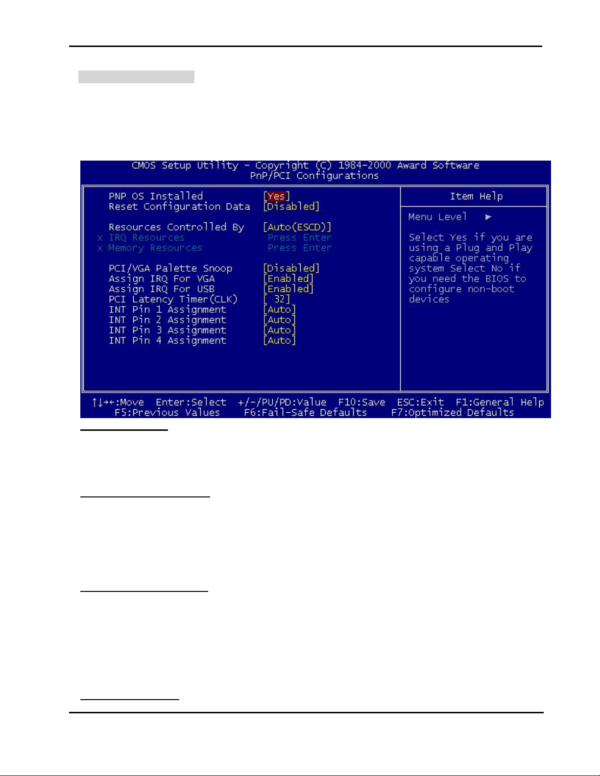
PnP/PCI Configuration
This section describes conf iguring the PCI bus system. PCI, or Peripheral Component Interconnect, is a
system which allows I/O devices to operate at speeds nearing the speed the CPU itself uses when
communic ating with its own special com ponents. This s ection covers som e very technical items and it is
strongly recommended that only experienced users should make any changes to the default settings.
PNP OS Installed
Select Yes if the system operating environment is Plug-and-Play aware (e.g. Windows 95).
The Choice: Yes, No.
Reset Configuration Data
Normally, you leave this field Disabled. Select Enabled to reset Extended System Configuration Data
(ESCD) when you exit Setup if you have installed a new add-on Card and the system reconfiguration has
caused such a serious conflict that the operating system cannot boot.
The Choice: Enabled, Disabled.
Resources Controlled by
The Award Plug and Play BIOS has the capacity to automatically configure all of the boot and Plug and
Play compatible devices. However, this capability means absolutely nothing unless you are using a Plug
and Play operating system such as Windows95. If you set this field to “manual” choose specific
resources by going into each of the sub menu that follows this field.
The Choice: Auto (ESCD), Manual.
► IRQ Resources
BIOS Setup
4-23
Page 45

NEX 6620A User's Guide Rev. B0 0301
Press <Enter> to enter the sub-menu, and you will see a sub-menu.
IRQ Assigned To
This item allows you to determine the IRQ assigned to PCI Device or Reserved.
The Choice: PCI Device, Reserved.
► Memory Resources
Press <Enter> to enter the sub-menu, and you will see a sub-menu.
Reserved Memory Base
Some add-in cards ask for a specific address space in the system memory. This field specifies the
memory base (start address) of the reserved memory space.
The Choice: N/A, C800, CC00, D000, D400, D800, DC00.
Reserved Memory Length
This item is available only when the Used MEM Base Addr has been assigned a base address. It
specifies the memory size for the add-in card used.
The Choice: 8K, 16K, 32K, 64K
PCI/VGA Palette Snoop
Leave this field at Disabled.
The Choice: Enabled, Disabled.
Assign IRQ For VGA/USB
Enable/Disable to assign a IRQ for VGA/USB.
The Choice: Enabled, Disabled.
PCI Latency Timer(CLK)
This item is used to specify assign PCI Latency Timer value.
The Choice: 0-255.
INT Pin 1~4 Assignment
This item is used to specify assign PCI device Interrupt line use IRQ number. BIOS will show that what
PCI device will be assign in Item Help.
The Choice: Auto, 3, 4, 5, 7, 9, 10, 11, 12, 14, 15.
BIOS Setup
4-24
Page 46
NEX 6620A User's Guide Rev. B0 0301
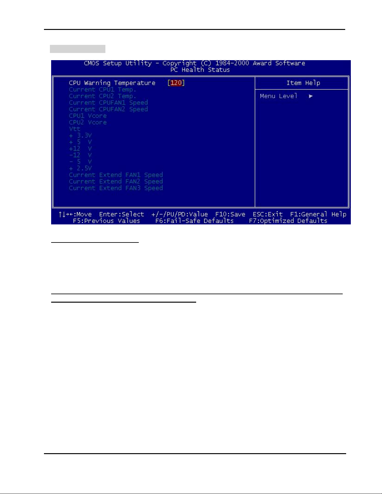
PC Health Status
CPU Warning Temperature
This item is used to specify a thermal standard for CPU. If CPU temperature reaches the specified
standard, the system will issue a warning and allows you to prevent the CPU overheat problem.
The Choice: 30-120.
Current CPU1/CPU2 Temp., Current CPUFAN1/2 Speed, CPU1/2 Vcore, Vtt, +3.3/+ 5/+ 12/12/- 5/+2.5V, Current Extend FAN1/2/3 Speed
These items display the current status of all of the monitored hardware devices/components such as CPU
voltages, temperatures and fans’s speed.
BIOS Setup
4-25
Page 47
NEX 6620A User's Guide Rev. B0 0301
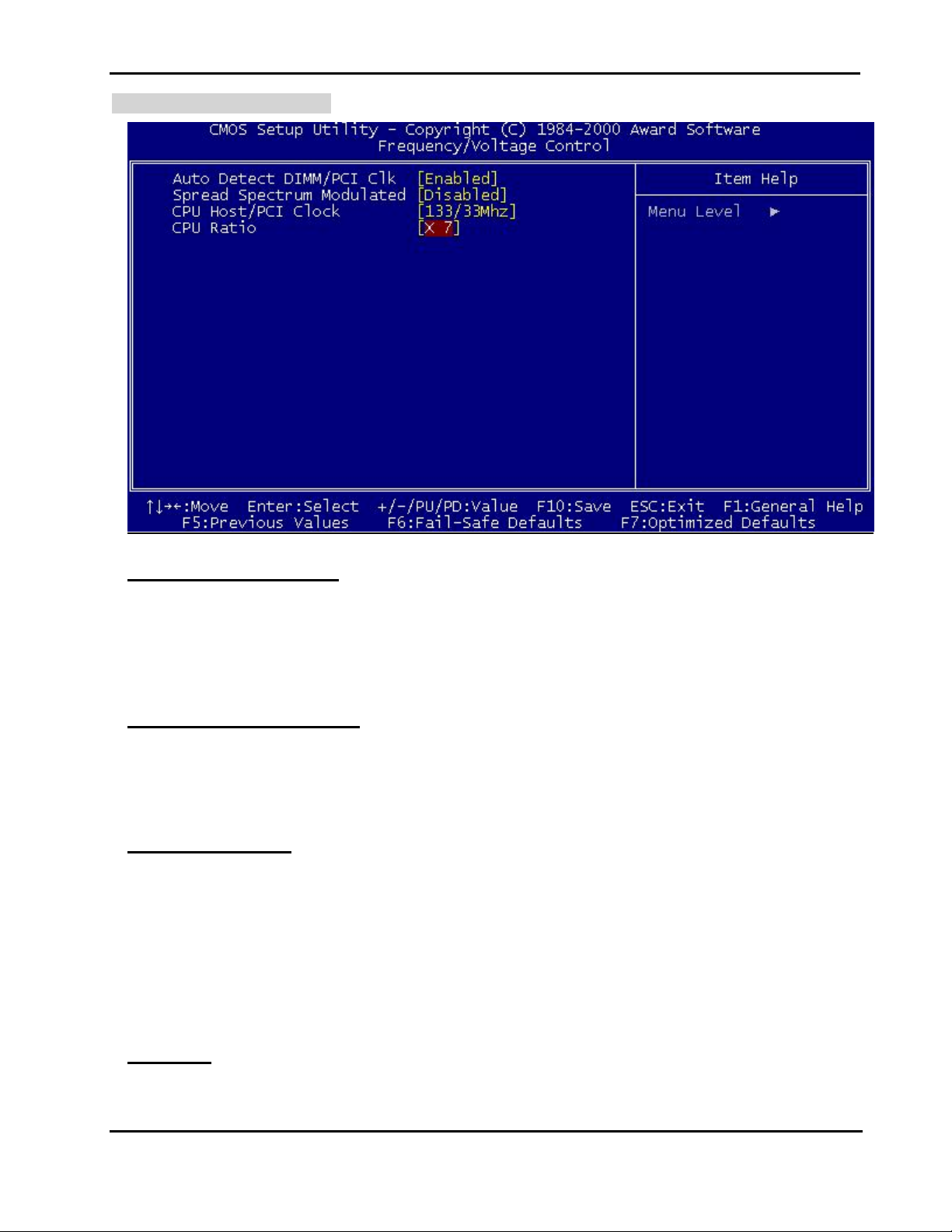
Frequency/Voltage Control
Auto Detect DIMM/PCI Clk
Use this item to enable or disable the feature of auto detecting the clock frequency of the installed DRAM
DIMMs and PCI cards.
The Choice: Enabled, Disabled.
Spread Spectrum Modulated
This item is used to enable or disable the clock generator’s Spread Spectrum feature.
The Choice: Enabled, Disabled.
CPU Host/PCI Clock
This item allows you to set up the CPU/PCI clock, but this function depends on different CPU performance.
It is highly recommended to use the default setting by the CPU ID auto detect. The standard CPU Clock
will be 100MHZ or 133MHZ. If you set the wrong CPU clock cause the system can’t power on, pleas e do
hardware clear the CMOS to reset the BIOS default value then setup the correct CPU clock. Or you can
press INSERT key to power on system to restore the BIOS default.
The Choice: Default, 100/33Mhz, 133/33Mhz.
CPU Ratio
This item allows you to set up the CPU clock ratio, but this function depends on different CPU performance.
It is only effective for those clock ratio haven’t been locked.
BIOS Setup
4-26
Page 48

NEX 6620A User's Guide Rev. B0 0301
The Choice: X3.0~X8.0.
Supervisor/User Password Setting
You can set either supervisor or user password, or both of then. The differences between are:
supervisor password : can enter and change the options of the setup menus.
user password : just can only enter but do not have the right to change the options of the setup
menus. When you select this function, the following message will appear at the
center of the screen to assist you in creating a password.
ENTER PASSWORD:
Type the password, up to eight characters in length, and press <Enter>. The pass word typed now will
clear any previously entered password from CMOS mem ory. You will be asked to confirm the password.
Type the password again and press <Enter>. You may also press <Esc> to abort the selection and not
enter a password.
To disable a password, just press <Enter> when you are prompted to enter the password. A message
will confirm the password will be disabled. Once the password is disabled, the system will boot and you
can enter Setup freely.
PASSWORD DISABLED
When a pass word has been enabled, you will be prompted to enter it every time you try to enter Setup.
This prevents an unauthorized person from changing any part of your system configuration.
Additionally, when a password is enabled, you can also require the BIOS to request a password every time
your system is rebooted. This would prevent unauthorized use of your computer.
You determine when the password is required within the BIOS Features Setup Menu and its Security
option (see Section 3). If the Security option is set to “System”, the password will be required both at boot
and at entry to Setup. If set to “Setup”, prompting only occurs when trying to enter Setup.
BIOS Setup
4-27
Page 49

NEX 6620A User's Guide Rev. B0 0301
Power-On Boot
After you have made all the changes to CMOS values and the system cannot boot with the CMOS values
selected in Setup, restart the system by turning it OFF then ON or Pressing the "RESET" button on the
system case. You may also restart by simultaneously press <Ctrl>, <Alt>, and <Delete> keys.
Upon restart the system, immediately press <Insert> to load BIOS default CMOS value for boot up.
BIOS Setup
4-28
Page 50

NEX 6620A User's Guide Rev. B0 0301
4-2 BIOS Reference - POST Message
During the Power On Self Test (POST), if the BIOS detects an err or requiring you to do som ething to fix, it
will either sound a beep code or display a message.
If a message is displayed, it will be accompanied by:
PRESS <F1> TO CONTINUE, <CTRL>-<ALT>-<ESC> OR <DEL> TO ENTER SETUP
POST Beep
Currently there is only one beep code in BIOS. This code indicates that a video err or has occurred and
the BIOS cannot initialize the video screen to display any additional information. This beep c ode consis ts
of a single long beep followed by two short beeps.
Error Messages
One or more of the f ollowing messages may be displayed if the BIOS detects an er ror during the POST .
This list includes messages for both the ISA and the EISA BIOS.
BIOS ROM checksum error-System halted.
The checksum of ROM address F0000H-FFFFFH is bad.
CMOS BATTERY HAS FAILED
CMOS battery is no longer functional. It should be replaced.
CMOS CHECKSUM ERROR
Checksum of CMOS is incorrect. This can indicate that CMOS has become corrupt. T his error m ay
have been caused by a weak battery. Check the battery and replace if necessary.
DISK BOOT FAILURE, INSERT SYSTEM DISK AND PRESS ENTER
No boot device was found. T his could mean that either a boot drive was not detec ted or the dr ive does
not contain proper system boot files. Insert a system disk into Drive A: and press <Enter>. If you
assumed the system would boot from the hard drive, m ake sure the controller is inserted correctly and
all cables are properly attached. Also be sure the disk is form atted as a boot device. T hen reboot the
system.
DISKETTE DRIVES OR TYPES MISMATCH ERROR - RUN SETUP
Type of diskette drive installed in the system is different from the CMOS definition. Run Setup to
reconfigure the drive type correctly.
DISPLAY SWITCH IS SET INCORRECTLY
Display switch on the motherboard can be set to either m onoc hrome or color. This indicates the switch
is set to a different setting than indicated in Setup. Determine which setting is correct, and then
either turn off the system and change the jumper, or enter Setup and change the VIDEO selection.
BIOS Setup
4-29
Page 51

NEX 6620A User's Guide Rev. B0 0301
DISPLAY TYPE HAS CHANGED SINCE LAST BOOT
Since last powering off the system, the display adapter has been changed. You must configure the
system for the new display type.
EISA Configuration Checksum Error
PLEASE RUN EISA CONFIGURATION UTILITY
The EISA non-volatile RAM checksum is incorrect or cannot correctly read the EISA slot. This can
indicate either the EISA non-volatile memory has become corrupt or the slot has been configured
incorrectly. Also be sure the card is installed firmly in the slot.
EISA Configuration Is Not Complete
PLEASE RUN EISA CONFIGURATION UTILITY
The slot configuration information stored in the EISA non-volatile memory is incomplete.
Note: When either of these err ors appear, the system will boot in ISA mode, which allows you to
run the EISA Configuration Utility.
ERROR ENCOUNTERED INITIALIZING HARD DRIVE
Hard drive cannot be initialized. Be su re the adapter is installed correctly and all cables are correc tly
and firmly attached. Also be sure the correct hard drive type is selected in Setup.
ERROR INITIALIZING HARD DISK CONTROLLER
Cannot initialize controller. Make sure the cor d is co rrec tly and firmly installed in the bus. Be s ure the
correct hard drive type is selected in Setup. Also check to see if any jumper needs to be set correc tly
on the hard drive.
FLOPPY DISK CNTRLR ERROR OR NO CNTRLR PRESENT
Cannot find or initialize the floppy drive controller. make sur e the controller is installed cor rectly and
firmly. If there are no floppy drives installed, be sure the Diskette Drive selection in Setup is set to
NONE.
FLOOPY DISK(S) fail (80)
Unable to reset floppy subsystem.
FLOOPY DISK(S) fail (40)
Floppy Type dismatch.
Hard Disk(s) fail (80)
HDD reset failed
Hard Disk(s) fail (40)
HDD controller diagnostics failed.
Hard Disk(s) fail (20)
HDD initialization error.
Hard Disk(s) fail (10)
Unable to recalibrate fixed disk.
BIOS Setup
4-30
Page 52

NEX 6620A User's Guide Rev. B0 0301
Hard Disk(s) fail (08)
Sector Verify failed.
Invalid EISA Configuration
PLEASE RUN EISA CONFIGURATION UTILITY
The non-volatile mem ory containing EISA configuration inform ation was programm ed incorrectly or has
become corrupt. Re-run EISA configuration utility to correctly program the memory.
NOTE: W hen this error appears, the system will boot in ISA mode, which allows you to run the
EISA Configuration Utility.
KEYBOARD ERROR OR NO KEYBOARD PRESENT
Cannot initialize the keyboard. Make s ure the keyboard is attached correctly and no keys are being
pressed during the boot.
If you are purposely configurating the system without a keyboard, set the error halt condition in Setup to
HALT ON ALL, BUT KEYBOARD. This will cause the BIOS to ignore the missing keyboard and
continue the boot.
Keyboard is locked out-Unlock the key
BIOS detect the keyboard is locked. P17 of keyboard controller is pulled low.
Manufacturing POST loop
System will repeat POST procedure infinitely while the P15 of keyboard controller is pull low. T his is
also used for M/B burn in test.
Memory Address Error at ...
Indicates a memory address error at a specific location. You can use this location along with the
memory map for your system to find and replace the bad memory chips.
Memory test fail
BIOS reports the memory test fail if the onboard memory is tested error.
Memory parity Error at ...
Indicates a mem ory parity error at a specific loc ation. You can use this loc ation along with the m em ory
map for your system to find and replace the bad memory chips.
MEMORY SIZE HAS CHANGED SINCE LAST BOOT
Memory has been added or removed since the last boot. In EISA mode use Configuration Utility to
reconfigure the memory configuration. In ISA mode enter Setup and enter the new memory size in
the memory fields.
Memory Verify Error at ...
Indicates an error verifying a value already written to memory. Use the location along with your
system's memory map to locate the bad chip.
OFFENDING ADDRESS NOT FOUND
This message is used in conjunction with the I/O CHANNEL CHECK and RAM PARITY ERROR
messages when the segment that has caused the problem cannot be isolated.
BIOS Setup
4-31
Page 53

NEX 6620A User's Guide Rev. B0 0301
OFFENDING SEGMENT:
This message is used in conjunction with the I/O CHANNEL CHECK and RAM PARITY ERROR
messages when the segment that has caused the problem has been isolated.
PRESS A KEY TO REBOOT
This will be displayed at the bottom screen when an error occurs that requires you to reboot. Press any
key and the system will reboot.
PRESS F1 TO DISABLE NMI, F2 TO REBOOT
When BIOS detec ts a Non-maskable Interrupt condition during boot, this will allow you to disable the
NMI and continue to boot, or you can reboot the system with the NMI enabled.
RAM PARITY ERROR - CHECKING FOR SEGMENT ...
Indicates a parity error in Random Access Memory.
Should Be Empty But EISA Board Found
PLEASE RUN EISA CONFIGURATION UTILITY
A valid board ID was found in a slot that was configured as having no board ID.
NOTE; When this error appears, the system will boot in ISA mode, which allows you to run the
EISA Configuration Utility.
Should Have EISA Board But Not Found
PLEASE RUN EISA CONFIGURATION UTILITY
The board installed is not responding to the ID request, or no board ID has been found in the indicated
slot.
NOTE: When this error appears, the system will boot in ISA mode, which allows you to run the
EISA Configuration Utility.
Slot Not Empty
Indicates that a slot designated as empty by the EISA Configuration Utility actually contains a board.
NOTE: When this error appears, the system will boot in ISA mode, which allows you to run the
EISA Configuration Utility.
SYSTEM HALTED, (CTRL-ALT-DEL) TO REBOOT ...
Indicates the present boot attempt has been aborted and the system must be rebooted. Press and
hold down the CTRL and ALT keys and press DEL.
Wrong Board In Slot
PLEASE RUN EISA CONFIGURATION UTILITY
The board ID does not match the ID stored in the EISA non-volatile memory.
NOTE: When this error appears, the system will boot in ISA mode, which allows you to run the
EISA Configuration Utility.
BIOS Setup
4-32
Page 54

NEX 6620A User's Guide Rev. B0 0301
4-3 BIOS Reference - POST Codes
POST (hex) Description
CFh Test CMOS R/W functionality.
C0h Early chipset initialization:
-Disable shadow RAM
-Disable L2 cache (socket 7 or below)
-Program basic chipset registers
C1h Detect memory
-Auto-detection of DRAM size, type and ECC.
-Auto-detection of L2 cache (socket 7 or below)
C3h Expand compressed BIOS code to DRAM
C5h Call chipset hook to copy BIOS back to E000 & F000 shadow RAM.
0h1 Expand the Xgroup codes locating in physical address 1000:0
02h Reserved
03h Initial Superio_Early_Init switch.
04h Reserved
05h 1. Blank out screen
2. Clear CMOS error flag
06h Reserved
07h 1. Clear 8042 interface
2. Initialize 8042 self-test
08h 1. Test special keyboard controller for Winbond 977 series Super I/O chips.
2. Enable keyboard interface.
09h Reserved
0Ah 1. Disable PS/2 mouse interface (optional).
2. Auto detect ports for keyboard & mouse followed by a port & interface swap (optional).
3. Reset keyboard for Winbond 977 series Super I/O chips.
0Bh Reserved
0Ch Reserved
0Dh Reserved
0Eh Test F000h segment shadow to see whether it is R/W-able or not. If test fails, keep beeping
0Fh Reserved
10h Auto detect flash type to load appropriate flash R/W codes into the run time area in F000
BIOS Setup
the speaker.
4-33
Page 55

NEX 6620A User's Guide Rev. B0 0301
POST (hex) Description
for ESCD & DMI support.
11h Reserved
12h Use walking 1’s algorithm to check out interface in CMOS circuitry. Also set real-time
clock power status, and then check for override.
13h Reserved
14h Program chipset default values into chipset. Chipset default values are MODBINable by
OEM customers.
15h Reserved
16h Initial Early_Init_Onboard_Generator switch.
17h Reserved
18h Detect CPU information including brand, SMI type (Cyrix or Intel) and CPU level (586 or
686).
19h Reserved
1Ah Reserved
1Bh Initial interrupts vector table. If no special specified, all H/W interrupts are directed to
SPURIOUS_INT_HDLR & S/W interrupts to SPURIOUS_soft_HDLR.
1Ch Reserved
1Dh Initial EARLY_PM_INIT switch.
1Eh Reserved
1Fh Load keyboard matrix (notebook platform)
20h Reserved
21h HPM initialization (notebook platform)
22h Reserved
23h 1. Check validity of RTC value:
e.g. a value of 5Ah is an invalid value for RTC minute.
2. Load CMOS settings into BIOS stack. If CMOS checksum fails, use default value
instead.
3. Prepare BIOS resource map for PCI & PnP use. If ESCD is valid, take into consideration
of the ESCD’s legacy information.
4. Onboard clock generator initialization. Disable respective clock resource to empty PCI
& DIMM slots.
BIOS Setup
5. Early PCI initialization:
-Enumerate PCI bus number
-Assign memory & I/O resource
-Search for a valid VGA device & VGA BIOS, and put it into C000:0.
4-34
Page 56

NEX 6620A User's Guide Rev. B0 0301
POST (hex) Description
24h Reserved
25h Reserved
26h Reserved
27h Initialize INT 09 buffer
28h Reserved
29h 1. Program CPU internal MTRR (P6 & PII) for 0-640K memory address.
2. Initialize the APIC for Pentium class CPU.
3. Program early chipset according to CMOS setup. Example: onboard IDE controller.
4. Measure CPU speed.
5. Invoke video BIOS.
2Ah Reserved
2Bh Reserved
2Ch Reserved
2Dh 1. Initialize multi-language
2. Put information on screen display, including Award title, CPU type, CPU speed ….
2Eh Reserved
2Fh Reserved
30h Reserved
31h Reserved
32h Reserved
33h Reset keyboard except Winbond 977 series Super I/O chips.
34h Reserved
35h Reserved
36h Reserved
37h Reserved
38h Reserved
39h Reserved
3Ah Reserved
3Bh Reserved
3Ch Test 8254
3Dh Reserved
3Eh Test 8259 interrupt mask bits for channel 1.
3Fh Reserved
BIOS Setup
4-35
Page 57

NEX 6620A User's Guide Rev. B0 0301
POST (hex) Description
40h Test 8259 interrupt mask bits for channel 2.
41h Reserved
42h Reserved
43h Test 8259 functionality.
44h Reserved
45h Reserved
46h Reserved
47h Initialize EISA slot
48h Reserved
49h 1. Calculate total memory by testing the last double word of each 64K page.
2. Program write allocation for AMD K5 CPU.
4Ah Reserved
4Bh Reserved
4Ch Reserved
4Dh Reserved
4Eh 1. Program MTRR of M1 CPU
2. Initialize L2 cache for P6 class CPU & program CPU with proper cacheable range.
3. Initialize the APIC for P6 class CPU.
4. On MP platform, adjust the cacheable range to smaller one in case the cacheable
ranges between each CPU are not identical.
4Fh Reserved
50h Initialize USB
51h Reserved
52h Test all memory (clear all extended memory to 0)
53h Reserved
54h Reserved
55h Display number of processors (multi-processor platform)
56h Reserved
57h 1. Display PnP logo.
58h Reserved
59h Initialize the combined Trend Anti-Virus code.
BIOS Setup
2. Early ISA PnP initialization
-Assign CSN to every ISA PnP device.
4-36
Page 58

NEX 6620A User's Guide Rev. B0 0301
POST (hex) Description
5Ah Reserved
5Bh (Optional Feature)
Show message for entering AWDFLASH.EXE from FDD (optional)
5Ch Reserved
5Dh 1. Initialize Init_Onboard_Super_IO switch.
2. Initialize Init_Onbaord_AUDIO switch.
5Eh Reserved
5Fh Reserved
60h Okay to enter Setup utility; i.e. not until this POST stage can users enter the CMOS setup
utility.
61h Reserved
62h Reserved
63h Reserved
64h Reserved
65h Initialize PS/2 Mouse
66h Reserved
67h Prepare memory size information for function call:
INT 15h ax=E820h
68h Reserved
69h Turn on L2 cache
6Ah Reserved
6Bh Program chipset registers according to items described in Setup & Auto-configuration table.
6Ch Reserved
6Dh 1. Assign resources to all ISA PnP devices.
2. Auto assign ports to onboard COM ports if the corresponding item in Setup is set to
“AUTO”.
6Eh Reserved
6Fh 1. Initialize floppy controller
2. Set up floppy related fields in 40:hardware.
70h Reserved
71h Reserved
72h Reserved
73h (Optional Feature)
BIOS Setup
4-37
Page 59

NEX 6620A User's Guide Rev. B0 0301
POST (hex) Description
Enter AWDFLASH.EXE if :
-AWDFLASH is found in floppy drive.
-ALT+F2 is pressed
74h Reserved
75h Detect & install all IDE devices: HDD, LS120, ZIP, CDROM…..
76h Reserved
77h Detect serial ports & parallel ports.
78h Reserved
79h Reserved
7Ah Detect & install co-processor
7Bh Reserved
7Ch Reserved
7Dh Reserved
7Eh Reserved
7Fh 1. Switch back to text mode if full screen logo is supported.
-If errors occur, report errors & wait for keys
-If no errors occur or F1 key is pressed to continue:
2. Clear EPA or customization logo.
80h Reserved
81h Reserved
E8POST.ASM starts
82h 1. Call chipset power management hook.
2. Recover the text fond used by EPA logo (not for full screen logo)
3. If password is set, ask for password.
83h Save all data in stack back to CMOS
84h Initialize ISA PnP boot devices
85h 1. USB final Initialization
2. NET PC: Build SYSID structure
3. Switch screen back to text mode
BIOS Setup
4. Set up ACPI table at top of memory.
5. Invoke ISA adapter ROMs
6. Assign IRQs to PCI devices
7. Initialize APM
4-38
Page 60

NEX 6620A User's Guide Rev. B0 0301
POST (hex) Description
8. Clear noise of IRQs.
86h Reserved
87h Reserved
88h Reserved
89h Reserved
90h Reserved
91h Reserved
92h Reserved
93h Read HDD boot sector information for Trend Anti-Virus code
94h 1. Enable L2 cache
2. Program boot up speed
3. Chipset final initialization.
4. Power management final initialization
5. Clear screen & display summary table
6. Program K6 write allocation
7. Program P6 class write combining
95h 1. Program daylight saving
2. Update keyboard LED & typematic rate
96h 1. Build MP table
2. Build & update ESCD
3. Set CMOS century to 20h or 19h
4. Load CMOS time into DOS timer tick
5. Build MSIRQ routing table.
FFh Boot attempt (INT 19h)
BIOS Setup
4-39
Page 61
NEX 6620A User's Guide Rev. B0 0301
Appendix : Digital I/O
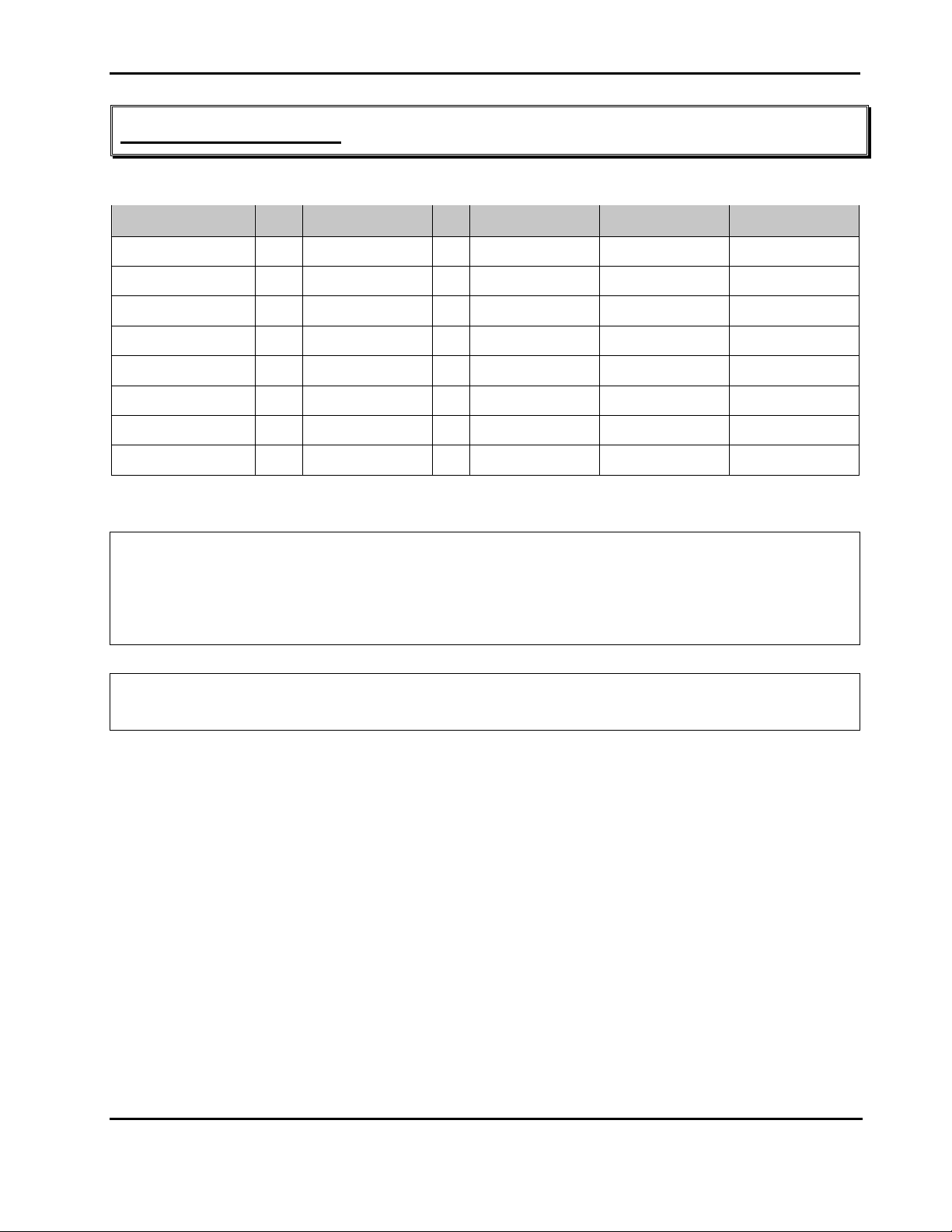
Digital I/O Control Table:
IO Port (hex) Bit Pin Name Bit = 1 Bit = 0 Locate
84B 0 Digital Input 1 Input High Input Low J15.1
84B 1 Digital Input 2 Input High Input Low J15.3
84B 2 Digital Input 3 Input High Input Low J15.5
84B 3 Digital Input 4 Input High Input Low J15.7
84B 4 Digital Output 1 Output High Output Low J15.2
84B 5 Digital Output 2 Output High Output Low J15.4
84B 6 Digital Output 3 Output High Output Low J15.6
84B 7 Digital Output 4 Output High Output Low J15.8
Programming Example:
Example 1: Set Digital_Output_1 output High
Mov DX, 84Bh ; Set I/O Port
In AL, DX ; Read Register Data
Or AL, 00010000b ; Set bit4 = 1 let Digital_Output_1 output High
Out DX, AL ; Set Register Data
Example 2: Read Digital_Output_1 output High
Mov DX, 84Bh ; Set I/O Port
In AL, DX ; Read Register Data, Bit 0 is Digital_Input_1 data.
Appendix
i
 Loading...