

Page 1
NEIO-B1812 Quick Reference Guide
Ver A. (P/N: 60177A0584X00)
Hardware Specications
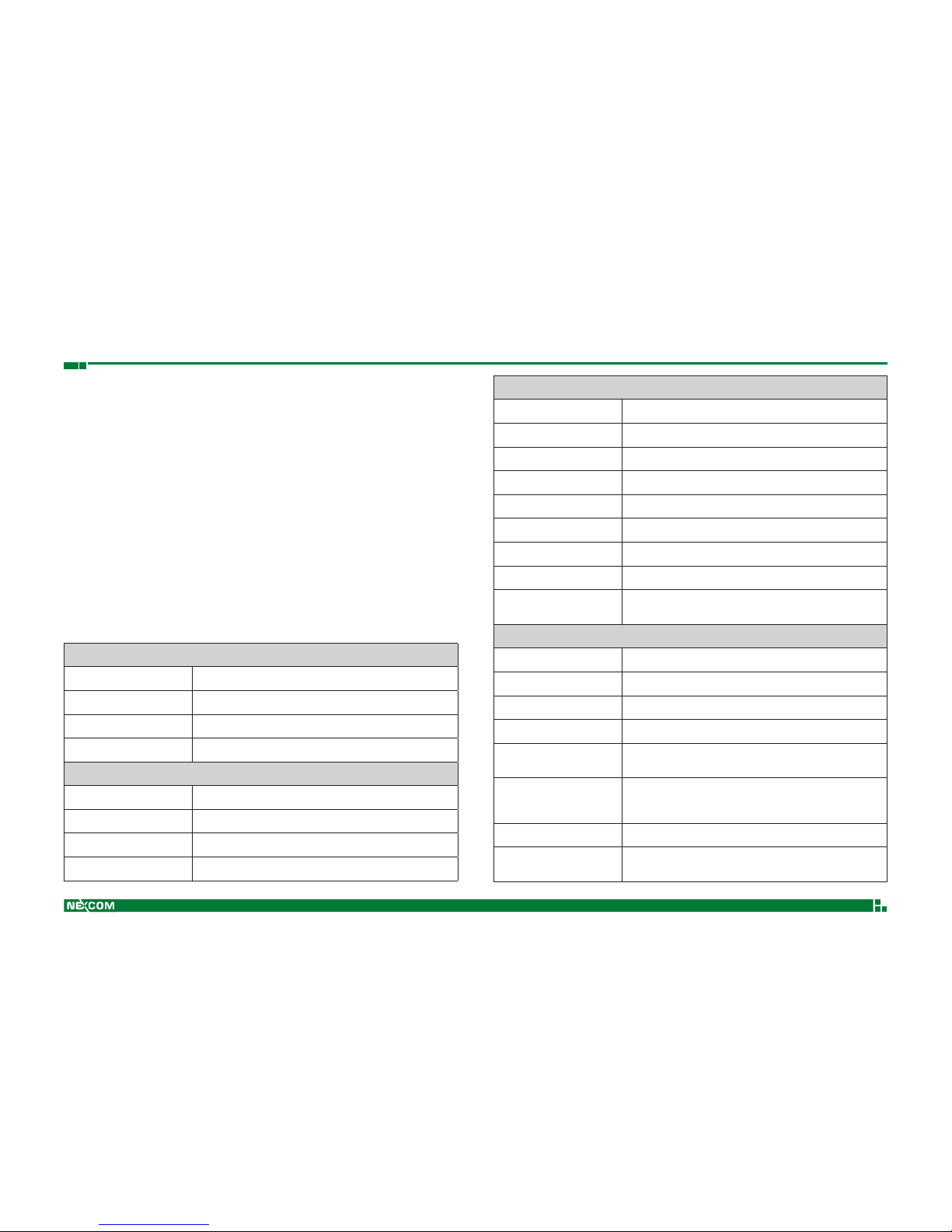
General Specications
Dimensions (WxHxD) 155 x 95 x 57.4 mm
Weight 324 g (±20%)
Mounting DIN-Rail (35mm) / wall mount
Operating Temperature 0 ~ +55 °C
Power Input
Power Input Range 24VDC (±20%)
Electrical Isolation 2.5 KV
Terminal Block Spring type (3P, 5.00 mm)
Cross Sections 0.2~2.5mm² / AWG 26~12
Product Overview
NEIO-B1812 is a source type 16-ch digital input/16-ch digital output EtherCAT slave
module. The input lter of NEIO-B1812 is 1ms, and its normal input voltage is 24VDC. Its
normal output voltage is 24VDC, and it supports three types of loads - resistive, inductive
and capacitive. All of the NEIO modules are provided with high isolation protection, and
veried by the EtherCAT conformance test tool. The mixed I/O module is usually used
for fewer DI/O channels needed automation equipment. Mixed DI/O modules along with
pure DI or DO modules provide more exible module selection for users’ applications.
Digital Iutput
Channels 16
Input Type 24VDC (sink / source)
Input Filter 1ms
On-state Voltage, "1
"
9~24 V
DC
Off-state Voltage, "0
"
0~8 V
DC
Input Current 3.6 mA
Electrical Isolation 3 KV
Terminal Block Detachable screw terminals (90°, 10P, 5.00mm)
Cross Sections
Solid wire: 0.2~4mm² / AWG 28~12
Stranded wire: 0.2~2.5mm² / AWG 30~12
Digital Output
Channels 16
Output Type 24 VDC, (source)
Load Type Resistive, Inductive and Capacitive
Output Current Maximum: 500 mA/ch
Switching Time
OFF to ON - Maximum: 100 us
ON to OFF - Maximum: 150 us
Output Protection
Over Current Limit
Short Circuit Protection
Reverse Voltage Protection
Terminal Block Detachable screw terminals (90°, 10P, 5.00mm)
Cross Sections
Solid wire : 0.2~4mm² / AWG 28~12
Stranded wire : 0.2~2.5mm² / AWG 30~12
Page 2
NEIO-B1812 Quick Reference Guide
Ver A. (P/N: 60177A0584X00)
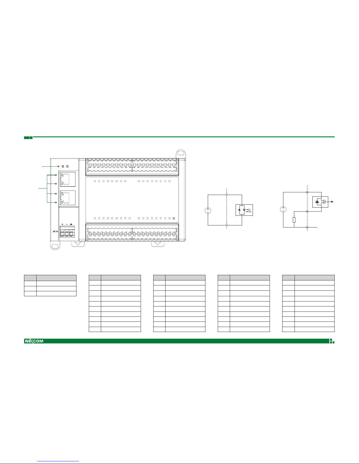
Product Appearance
1101
10 11 01
10
CN1 CN2 CN4
CN3
Channel Status LEDs
Status LEDs
LAN LEDs
Channel Status LEDs
(Group 1)
Channel Status LEDs
(Group 2)
Channel Status LEDs
CN5
PWR RUN
IN
OUT
Wiring Diagram
COM
V
in
GND
24V
24V
DO
(0~15)
External Internal
DI
(0~15)
External Internal
Pin Assignments
CN1: Power
Pin Description
1 V+
2 V-
3 GND
CN2: Digital Output
Pin Description
1 DO 0
2 DO 1
3 DO 2
4 DO 3
5 DO 4
6 DO 5
7 DO 6
8 DO 7
9 24V
10 GND
CN4: Digital Output
Pin Description
1 DO 8
2 DO 9
3 DO 10
4 DO 11
5 DO 12
6 DO 13
7 DO 14
8 DO15
9 24V
10 GND
CN3: Digital Input
Pin Description
1 COM
2 COM
3 DI 7
4 DI 6
5 DI 5
6 DI 4
7 DI 3
8 DI 2
9 DI 1
10 DI 0
CN5: Digital Input
Pin Description
1 COM
2 COM
3 DI 15
4 DI 14
5 DI 13
6 DI 12
7 DI 11
8 DI 10
9 DI 9
10 DI 8
DI (Sink/Source) DO (Source)
Page 3
NEIO-B1812 Quick Reference Guide
Ver A. (P/N: 60177A0584X00)
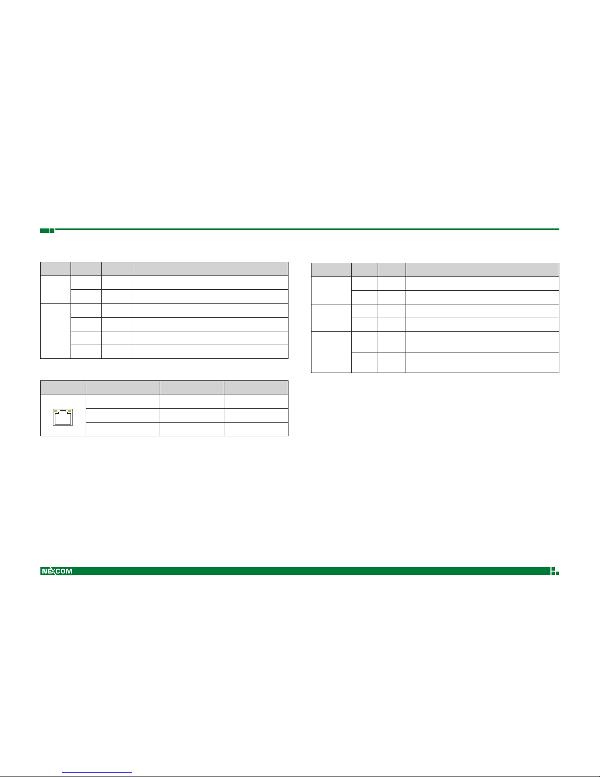
LED Indicators
Status LEDs
LED Status Color Description
PWR
On Green Power on (Power input range: 24 V
DC
, ±20%)
Off - Power off
RUN
On Green The module is in the Operational state
Blinking Green The module is in the Save-operational state
Blinking Green The module is in the Pre-operational state
Off - The module is in the Initial state
LAN LEDs
LED Communication Speed Link Act
ActLink
0 Off Off
10 Mbps O ff Blinking (Yellow)
100 Mbps On (Green) Blinking (Yellow)
Channel Status LEDs
LED Status Color Description
DI 0 ~ DI 15
On Green On-state voltage: 9~24 VDC (sink); 0~15 VDC (source)
Off - Off-state voltage : 0~8 VDC (sink); 16~24 VDC (source)
DO 0 ~ DO 15
On Green Digital output signal is set
Off - No digital output signal
24V
On Orange
24VDC external power supply for each DO group is
connected
Off -
24VDC external power supply for each DO group is not
connected
Note: NEIO series digital output module all requires a 24VDC external power supply for each DO channel group. With the DO 24VDC
LEDs you can diagnostic the status of external power supply.
 Loading...