

Page 1

www.nexcom.com
Single Board Computer
EBC 580 Series
User’s Manual
April-12-2006 Build
Nov-15-2006 Update
Prepared by Zack
Page 2

EBC 580 User’s Manual 1 Preface
Preface
Copyright
This publication, including all photographs, illustrations and software, is protected under international
copyright laws, with all rights reserved. No part of this manual maybe reproduced, copied, translated or
transmitted in any form or by any means without the prior written consent from NEXCOM International
Co., Ltd.
Version 1.0/1.1
Copyright 2006
Disclaimer
The information in this document is subject to change without prior notice and does not represent
commitment from NEXCOM International Co., LTD. However, users may update their knowledge of any
product in use by constantly checking its manual posted on our website: http://www.nexcom.com.
NEXCOM shall not be liable for direct, indirect, special, incidental, or consequential damages arising out
of the use of any product, nor for any infringements upon the rights of third parties, which may result from
such use. Any implied warranties of merchantability of fitness for any particular purpose is also
disclaimed.
Acknowledgements
The EBC 580 series is a trademark of NEXCOM international CO., LTD. All other product names
mentioned herein are registered trademarks of their respective owners.
Regulatory Compliance Statements
This section provides the FCC compliance statement for Class A devices and describes how to keep the
system CE compliant.
Federal Communications Commission (FCC) For Class A Device
This equipment has been tested and verified to comply with the limits for a Class A digital device, pursuant
to Part 15 of FCC Rules. These limits are designed to provide reasonable protection against harmful
interference when the equipment is operated in a commercial environment. This equipment generates, uses,
and can radiate radio frequency energy and, if not installed and used in accordance with the instructions,
may cause harmful interference to radio communications. Operation of this equipment in a residential area
(domestic environment) is likely to cause harmful interference, in which case the user will be required to
Page 3

EBC 580 User’s Manual 2 Preface
correct the interference (take adequate measures) at their own expense.
CE Certification
The product(s) described in this manual complies with all applicable European Union (CE) directives if it
has a CE marking. For computer systems to remain CE compliant, only CE-compliant parts may be used.
Maintaining CE compliance also requires proper cable and cabling techniques.
WARNINGS
Read and adhere to all warnings, cautions, and notices in this guide and
the documentation supplied with the chassis, power supply, and accessory
modules. If the instructions for the chassis and power supply are inconsistent
with these instructions or the instructions for accessory modules, contact
the supplier to find out how you can ensure that your computer meets
safety and regulatory requirements.
CAUTION
Electrostatic discharge (ESD) can damage NSA components. Do the
described procedures only at an ESD workstation. If no such station is
available, you can provide some ESD protection by wearing an antistatic
wrist strap and attaching it to a metal part of the computer chassis.
Safety Information
Before installing and using the EBC 580, note the following precautions:
Read all instructions carefully.
Do not place the unit on an unstable surface, cart, or stand.
Follow all warnings and cautions in this manual.
When replacing parts, ensure that your service technician uses parts specified by the manufacturer.
Avoid using the system near water, in direct sunlight, or near a hearing device.
Page 4

EBC 580 User’s Manual 3 Table of Content
Table of Content
Preface……………...……………..……………………………………….………….……..……………..1
Copyright………………..……………………………………….…………………………………….... 1
Disclaimer………………………..………………………………..…………………………………….. 1
Acknowledgements……………………………………………..……………………………..…..…… 1
Regulatory Compliance Statements……………………..…………………………………….……………1
Federal Communications Commission (FCC) For Class A Device……………..……….…………..…..…1
CE Certification………………………………………………………………………….……….………...2
Safety Information……………………………………………………………………….………..………..2
Table of Content………………………………………………………………………………….……. 3
Chapter 1 General Information
1.1 Main Feature…………………………………………………….…………………………………….. 6
1.2 Specifications……………………………………………………..……………………………………. 6
1.3 Power Consumption Measurement……………………………………………………………………..9
1.4 Board Layout…………………………………………………………………….…………………….10
1.5 Board Dimensions……………………………………………………….……………….……………12
Chapter 2Jumper Setting
2.1 Before You Begin……………………………………………..….……………………………………13
2.2 Precautions………………………………………………………………………………………... …..13
2.3 Setting Jumpers…………………………………………………………………………………… …..13
2.4 Location of Jumpers………………………………………………………………………………. …..15
2.5 Function of Jumper………………………….……………………………………………………........15
Chapter 3 Expansion
3.1 System Memory………………………………………………………………………………….…….26
3.2 Installing DIMM………………………………………………………………………………….. ….. 26
3.3 Installing Compact Flash………………………..…………………………………………………….. 29
Page 5

EBC 580 User’s Manual 4
Page 6

EBC 580 User’s Manual 5 Chapter 1
Chapter 1
General Information
Page 7
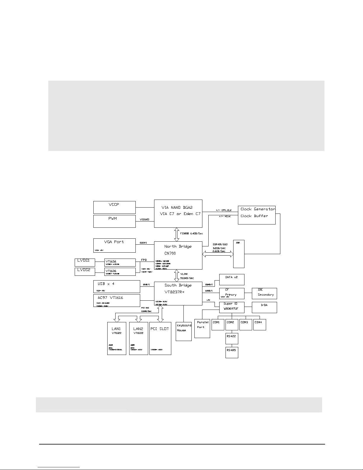
EBC 580 User’s Manual 6 Chapter 1
1.1 Main Feature
Support VIA® EDEN/C7 processors from 400MHz up to 1.5GHz
• VIA® CN700 and VIA® 8237R+ chipsets
• 184-pin DIMM x 1, support up to 1GB un-buffered non-ECC DDR 333/400 SDRAM
• Realtek® RTL8110SB Gigabit Ethernet Controller x 2 supporting two GbE LAN ports
• Support LVDS, CCFL, and DB-15 VGA Connector
• Support IDE and SATA HDD
• Compact Flash socket
• USB 2.0 Port x 4, COM x 4
1.2 Specifications
Figure 1.1: Block Diagram of EBC 580
System Architecture
- 5.25” Embedded SBC
CPU Support
- Eden V4 400MHZ or 1GHZ (5W)Î FANless Possibility
Page 8

EBC 580 User’s Manual 7 Chapter 1
- C7 1.5GHZ (12W) Î With CPU Cooler
Memory
- 1 x 184-pin DIMM
- Up to 1GB un-buffered non-ECC DDR 333/400 SDRAM
BIOS
- Plug & Play support
- Award System BIOS
- Advanced Power Management and Advanced Configuration &
Power Interface support
Chipset
- VIA® CN700
- VIA® 8237R+
LAN
- Realtek® RTL8110SB Gigabit Ethernet Controller x 2 supporting
two GbE LAN ports
Display
- LVDS1:VIA VT1636 transmitter, DF13-20DP, 20-pin connector x
2 for LVDS1 panel output
- LVDS2:VIA VT1636 transmitter, DF13-20DP, 20-pin connector x
2 for LVDS2 panel output
- CCFL:CCFL x 2 for LCD Panel Backlight Inverter Power
VGA:DB15 VGA Connector x 1
IDE
- HDD: Support IDE with 44 pin connector × 1 (Secondary)
- Compact Flash Socket x 1 (Primary)
SATA
- SATA x 2ports, support Raid 0,1
Audio
- VIA VT1616 CODEC for AC97 v2.1 CODEC
- CD audio in, Line in
- Microphone in and Speaker out Interface
I/O Interface
- SIO× 4, with 4x16C550 UARTs, COM 2 for RS 232/422/485 (40
pin 2.0 header with housing ×1)
- USB 2.0 x 4
- Parallel port: Box header 2x13 2.0mm 180-degree connector
- PS/2 connectors for Keyboard and Mouse
- Digital I/O: Pin header 2x4 2.54mm Male 180-degree connector
- IrDA:On board pin header for IrDA Tx Rx
- SMBus 2.0 controller: Pin header 1x3 2.0mm Male 180-degree
connector (One pin for GND)
- On board header for reset SW and HD active LED
- I2C: On board 3 pin header for I2C, one pin for GND
Expansion Slot
-
One 32 bit/33MHZ PCI Slot support PCI Expansion.
- PCI Expansion Slot position is compatible with EBC 569. And
support NEXCOM PCI Riser Card:
Page 9

EBC 580 User’s Manual 8 Chapter 1
EBK PCI1
EBK PCIR2
EBK PCIR3
I/O on Bracket
- Mic-in
- Speaker Out
- VGA DB-15 connector x 1
- RJ45 Gigabit Ethernet LAN port x 2
- USB x 2
- Mini-DIN for Keyboard/mouse x 1
System Management
- Derived from Super IO to support system monitor.
- Monitoring of 5 voltages, 3 temperature and 2 fans Speed.
5 voltage (For +3.3V, +5V, +12V, Vcore and +2.5V)
3 Temperatures (CPU, two external Temperature Sensor)
2 FANs speed (CPU and System FANs).
- Watchdog timeout can be programmable by Software from 1
second to 64 Sec.
Real Time Clock
- On-chip RTC with battery back up
- External Lithium battery x 1
Watchdog Timer
- 1-minute increments from 1 to 255 minutes
- 1-second increments from 1 to 255 seconds
Dimensions
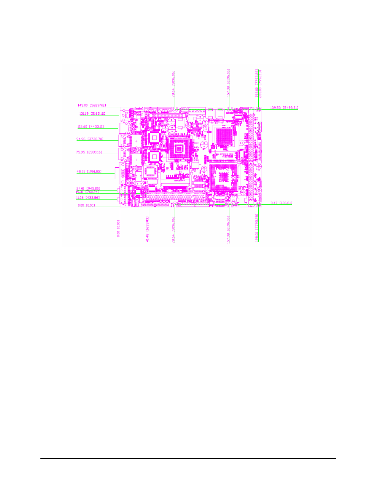
- 203mm(L) x 143mm(W)
Power Supply
- Three Pin Headers for AT/ATX mode switch
- +3.3V is converted from +5V
- 6 PIN Power Input Connector
- 3 PIN Jst connector to receive the 5Vsb input from Power Source
- Factory Default Setting is AT Mode
- ATX Mode
Power Required: +12V/+5V/+5Vsb
Support Power On push Button, Software Shutdown
function and LAN1 remote wake up only.
Two Pin Header for Power On Push Button
BIOS default setting is as shown below:
¾ POWER -SUPPLY TYPE Î [ATX]
¾ AUTO PWR-FAILURE RESUME Î [ON]
- AT mode
Power Required: +5V/+12V
No Power On push Button, No Software Shutdown function and No
LAN1 remote wake up
Page 10
EBC 580 User’s Manual 9 Chapter 1
Environments
- Board-level operating temperatures: -20°C to 60°C
- Storage temperatures: -20°C to 80°C
- Relative humidity: 10% to 90% (Non-condensing)
Certification
- CE
- FCC Class A
Ordering Information
EBC 580-715
RoHS Compliant. 5.25” Low Power Embedded Board with VIA C7 CPU 1.5G
w/VGA/ Dual LVDS/Audio/4 COMs/8 USB2.0 /Dual Gigabit LAN
EBC 580-E10
RoHS Compliant. 5.25” Low Power Embedded Board with VIA Eden V4 Bus CPU
1GHZ w/VGA/ Dual LVDS/Audio/4 COMs/8 USB2.0 /Dual Gigabit LAN
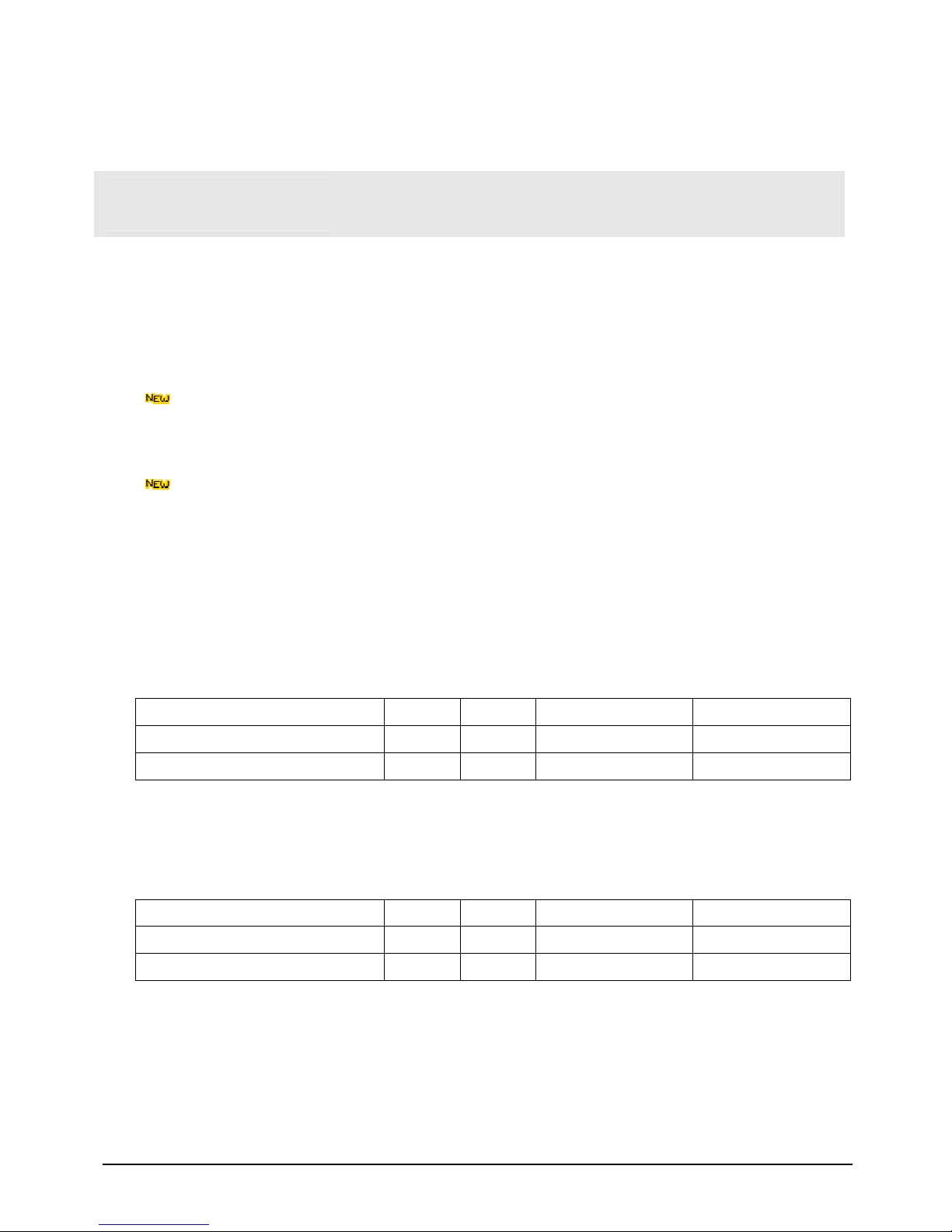
1.3 Power Consumption Measurement
EBC-580-715 Power Consumption
Power Type
+12V +5V +5VSB Mode
Power-On 0.81A 2.70A x AT Mode
HCT 1.30A 2.80A 0.28A ATX Mode
EBC-580-E10 Power Consumption
Power Type
+12V +5V +5VSB Mode
Power-On 0.46A 2.71A x AT Mode
HCT 0.39A 2.59A 0.04A ATX Mode
Page 11
EBC 580 User’s Manual 10 Chapter 1
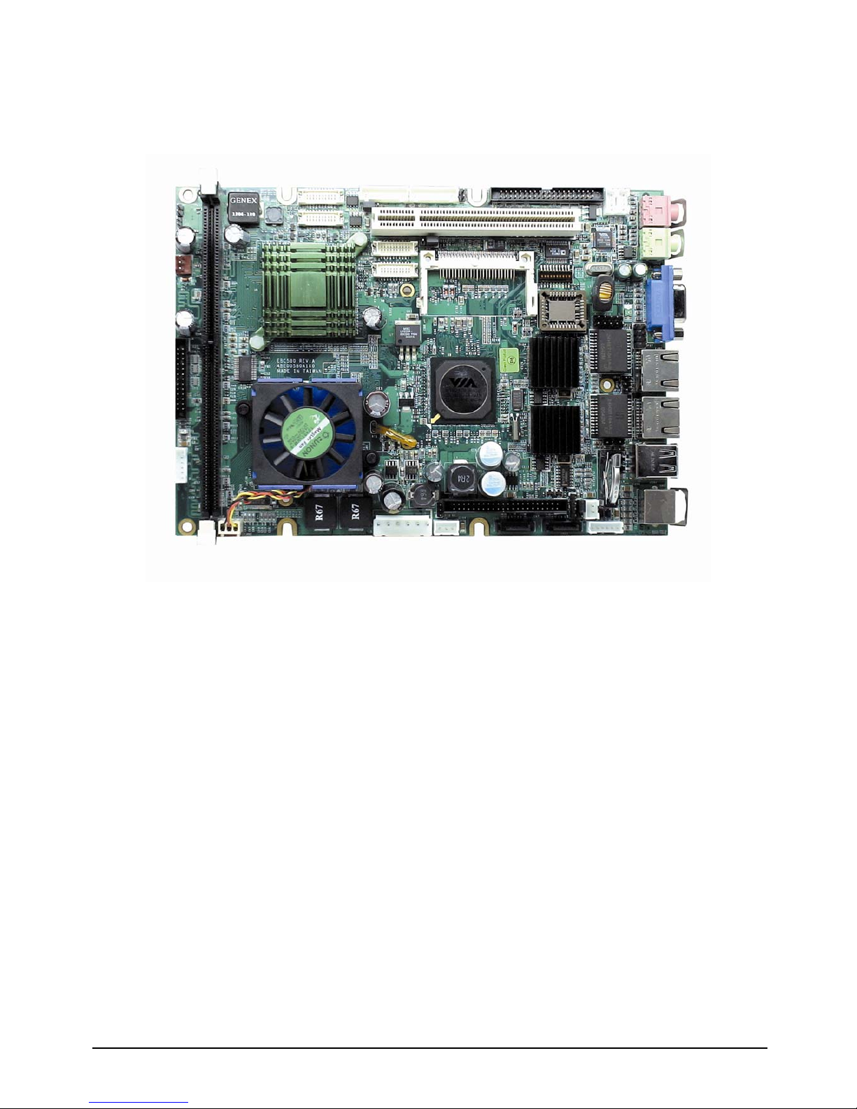
1.4 Board Layout
Figure 1.2: Overview of EBC 580
Page 12
EBC 580 User’s Manual 11 Chapter 1
1.5 Board Dimensions
Figure 1.3: Mechanical Drawing of the EBC 580
Page 13

EBC 580 User’s Manual 12
Chapter 2
Jumper Setting
Page 14

EBC 580 User’s Manual 13
This chapter of the User’s Manual describes how to set jumpers.
Note: The procedures that follow are generic for all EBC 580 series.
2.1 Before You Begin
Ensure you have a stable, clean working environment. Dust and dirt can get into components and cause a
malfunction. Use containers to keep small components separated.
Adequate lighting and proper tools can prevent you from accidentally damaging the internal components.
Most of the procedures that follow require only a few simple tools, including the following:
♦ A Philips screwdriver
♦ A flat-tipped screwdriver
♦ A set of jewelers Screwdrivers
♦ A grounding strap
♦ An anti-static pad
Using your fingers can disconnect most of the connections. It is recommended that you do not use
needle-nosed pliers to disconnect connections as these can damage the soft metal or plastic parts of the
connectors.
Before working on internal components, make sure that the power is off. Ground yourself before touching
any internal components, by touching a metal object. Static electricity can damage many of the electronic
components. Humid environment tend to have less static electricity than dry environments. A grounding
strap is warranted whenever danger of static electricity exists.
2.2 Precautions
Computer components and electronic circuit boards can be damaged by discharges of static electricity.
Working on the computers that are still connected to a power supply can be extremely dangerous. Follow
the guidelines below to avoid damage to your computer or yourself:
♦ Always disconnect the unit from the power outlet whenever you are working inside the case.
♦ If possible, wear a grounded wrist strap when you are working inside the computer case. Alternatively,
discharge any static electricity by touching the bare metal chassis of the unit case, or the bare metal
body of any other grounded appliance.
♦ Hold electronic circuit boards (such as the EBC 580 board) by the edges only. Do not touch the
components on the board unless it is necessary to do so. Don’t flex or stress the circuit board.
♦ Leave all components inside the static-proof packaging that they shipped with until they are ready for
installation.
♦ Use correct screws and do not over tighten screws.
Page 15
EBC 580 User’s Manual 14
2.3 Setting Jumpers
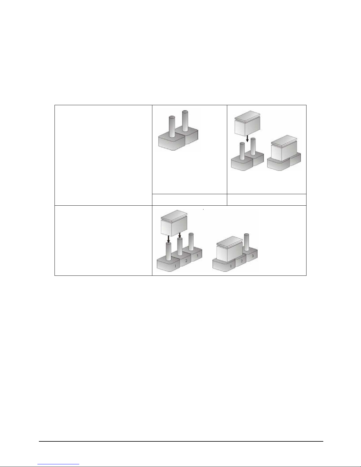
A jumper is the simplest kind of electric switch. It consists of two metal pins and a cap. When setting the
jumpers, ensure that the jumper caps are placed on the correct pins. When the jumper cap is placed on
both pins, the jumper is SHORT. If you remove the jumper cap, or place the jumper cap on just one pin,
the jumper is OPEN. Please see the following illustrations
The illustrations on the right show
a 2-pin jumper. When the jumper
cap is placed on both pins, the
jumper is SHORT. If you remove
the jumper cap, or place the
jumper cap on just one pin, the
jumper is OPEN.
Open (Off) Short (On)
These illustrations show a 3-pin
jumper. Pins 1 and 2 are SHORT.
Table 2-1: Setting Jumpers
Page 16
EBC 580 User’s Manual 15
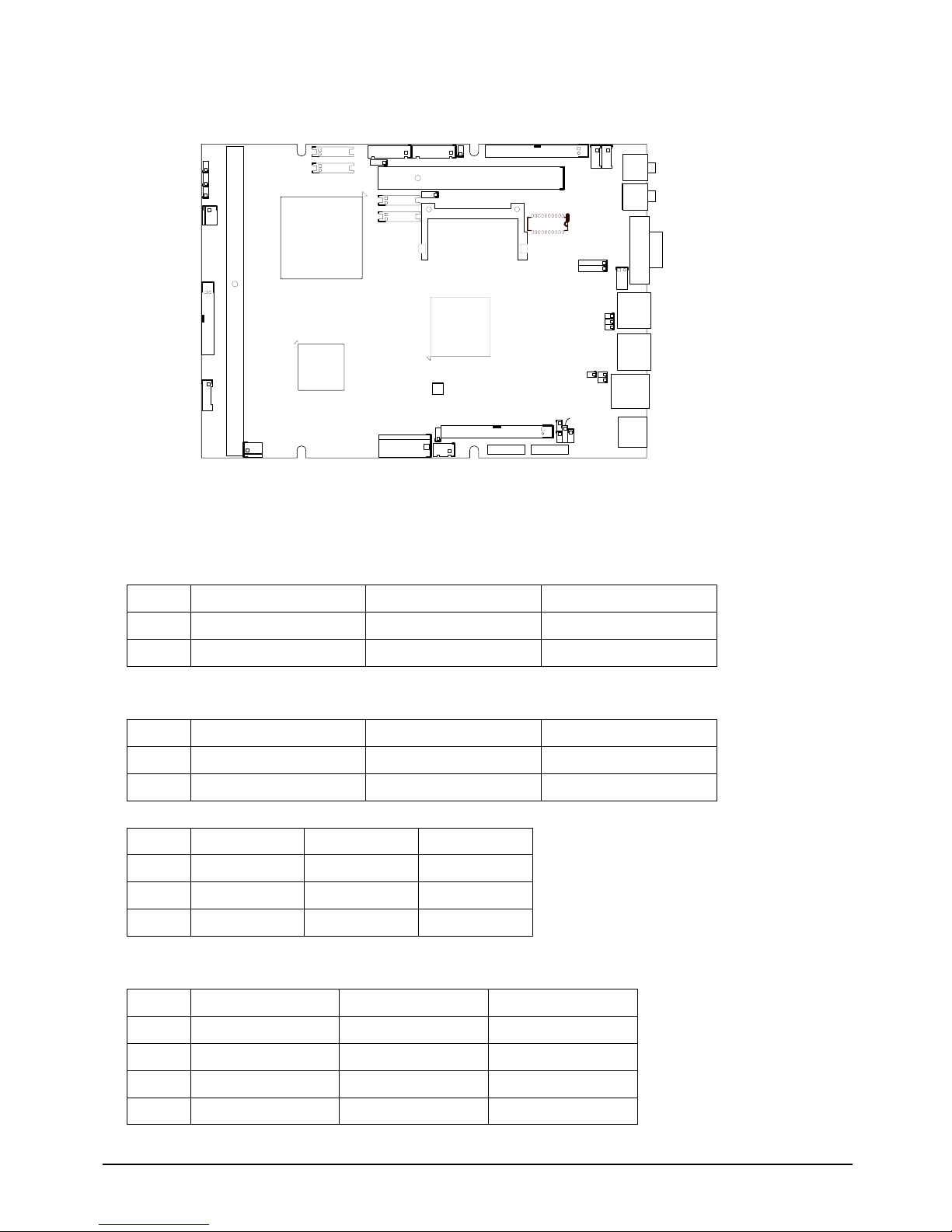
2.4 Location of Jumpers
PCI Slot
CON1
CPU
FAN1
JP18
JP2
NB
D
I
M
M
*
1
JP16
JP15
JP14
JP13
JP12
1
JP9
JP17
1
7
J7
J8
JP10
JP11
CN9
SATA2SATA1
SB
J4
J2 J3
JP3
JP8
JP4
JP1
JP7
JP6
1
JP5
J1
K/M
USB*2
1
1
LAN2
LAN1
1
1
1
1
1
FAN2
JP20
1
Compact Flash Socket
1
1 2
1
1
1
1
1
1
1
1
1
VGA
Line
out
Mic
Input
1
1
1
2
CN4
1
2
CN5
1
2
CN2
1
2
CN3
1
2
1
1
1
CN1
1
1
1 2
=PIN 1
IDE
1
2
JP191
SW1
0 9 8 7 6 5 4 3 2 1
ON
Figure 2-1: Jumper Location
2.5 Functions of Jumpers and Connectors
◎ J7(CD Input):JST 1x4 2.0mm Male 180-degree connector
Pin NO. Description Pin NO. Description
1 Left sound channel 3 GND
2 GND 4 Right sound channel
◎J8 (Line Input):JST 1x4 2.0mm Male 180-degree connector
Pin NO. Description Pin NO. Description
1 Left sound channel 3 GND
2 GND 4 Right sound channel
◎J1 (USB)::JST 1x6 2.0mm Male 180-degree connector
Pin NO. Description
1 VCC5 4 USBP3N
2 USBP2N 5 USBP3P
3 USBP2P 6 GND
◎J3 (CCFL)::JST 1x7 2.0mm Male 180-degree connector
Pin NO. Description Pin NO. Description
1 VDD5SAFE 5 GND
2 +12V 6 GND
3 +12V 7 Back light Enable
4 Back light control
Page 17
EBC 580 User’s Manual 16
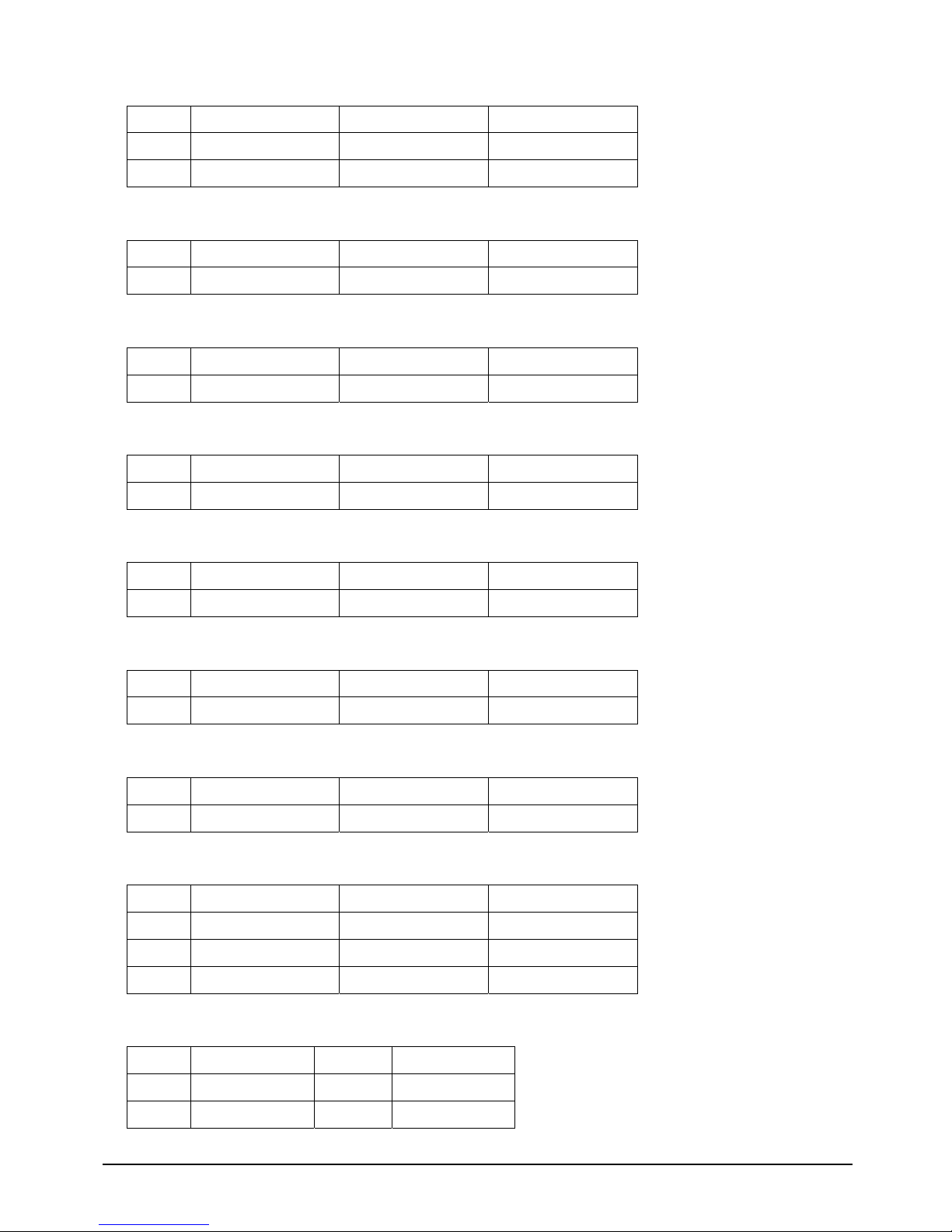
◎J4(5VSB connector):JST 1x3 2.5mm Male 180-degree connector
Pin NO. Description Pin NO. Description
1 PSON# 3 5VSB
2 GND
◎JP9(LAN2 Active LED):Pin header 1x2 2.54mm Male 180-degree connector
Pin NO. Description Pin NO. Description
1 Pull up to 3.3V 2 Active signal
◎JP12(LAN2 100 S peed LED):Pin header 1x2 2.54mm Male 180-degree connector
Pin NO. Description Pin NO. Description
1 Pull up to 3.3V 2 100 Speed signal
◎JP13(LAN2 1000 Speed LED):Pin header 1x2 2.54mm Male 180-degree connector
Pin NO. Description Pin NO. Description
1 Pull up to 3.3V 2 1000 Speed signal
◎JP14(LAN1 Active LED):Pin header 1x2 2.54mm Male 180-degree connector
Pin NO. Description Pin NO. Description
1 Pull up to 3Vdual 2 Active signal
◎JP15(LAN2 100 S peed LED):Pin header 1x2 2.54mm Male 180-degree connector
Pin NO. Description Pin NO. Description
1 Pull up to 3Vdual 2 100 Speed signal
◎JP16(LAN1 1000 Speed LED):Pin header 1x2 2.54mm Male 180-degree connector
Pin NO. Description Pin NO. Description
1 Pull up to 3Vdual 2 1000 Speed signal
◎JP11(IrDA) :Pin header 1x5 2.54mm Male 180-degree connector
Pin NO. Description Pin NO. Description
1 +5V 4 GND
2 NC 5 IRTX
3 IRRX
◎JP17(Digital I/O):Pin header 2x4 2.54mm Male 180-degree connector
Pin NO. Description Pin NO. Description
1 Digital Input 1 2 Digital Output 1
3 Digital Input 2 4 Digital Output 2
Page 18
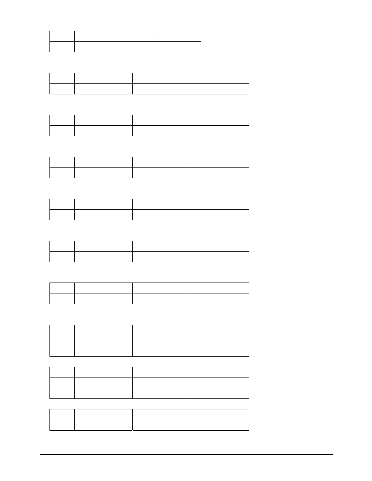
EBC 580 User’s Manual 17
5 Digital Input 3 6 Digital Output 3
7 Digital Input 4 8 Digital Output 4
◎JP4(CF mode select):Pin header 1x3 2.54mm Male 180-degree connector
Pin NO. Description Pin NO. Description
1-2 Master 2-3 Slave
◎JP8(CMOS Clear)
Pin NO. Description Pin NO. Description
1-2 Normal 2-3 Clear
◎JP7(Power Button)
Pin NO. Description Pin NO. Description
1 Power ON 2 GND
◎JP5(HD active LED):Pin header 1x2 2.54mm Male 180-degree connector
Pin NO. Description Pin NO. Description
1 Pull up to +5V 2 HD avtive signal
◎JP3(Panel power select):Pin header 1x3 2.54mm Male 180-degree connector
Pin NO. Description Pin NO. Description
1-2 +5V Input 2-3 +3V Input
◎JP1(RESET Button) :Pin header 1x2 2.54mm Male 180-degree connector
Pin NO. Description Pin NO. Description
1 RESET 2 GND
◎JP2(SMBus) :Pin header 1x3 2.0mm Male 180-degree connector
Pin NO. Description Pin NO. Description
1 SMBus Data 3 GND
2 SMBus Clock
◎JP18(I2CBus) :Pin header 1x3 2.0mm Male 180-degree connector
Pin NO. Description Pin NO. Description
1 SMBus Data 3 GND
2 SMBus Clock
◎JP20 (Power Select)
Pin NO. Description Pin NO. Description
1-2
AT power supply
2-3
A TX power supply
Page 19
EBC 580 User’s Manual 18
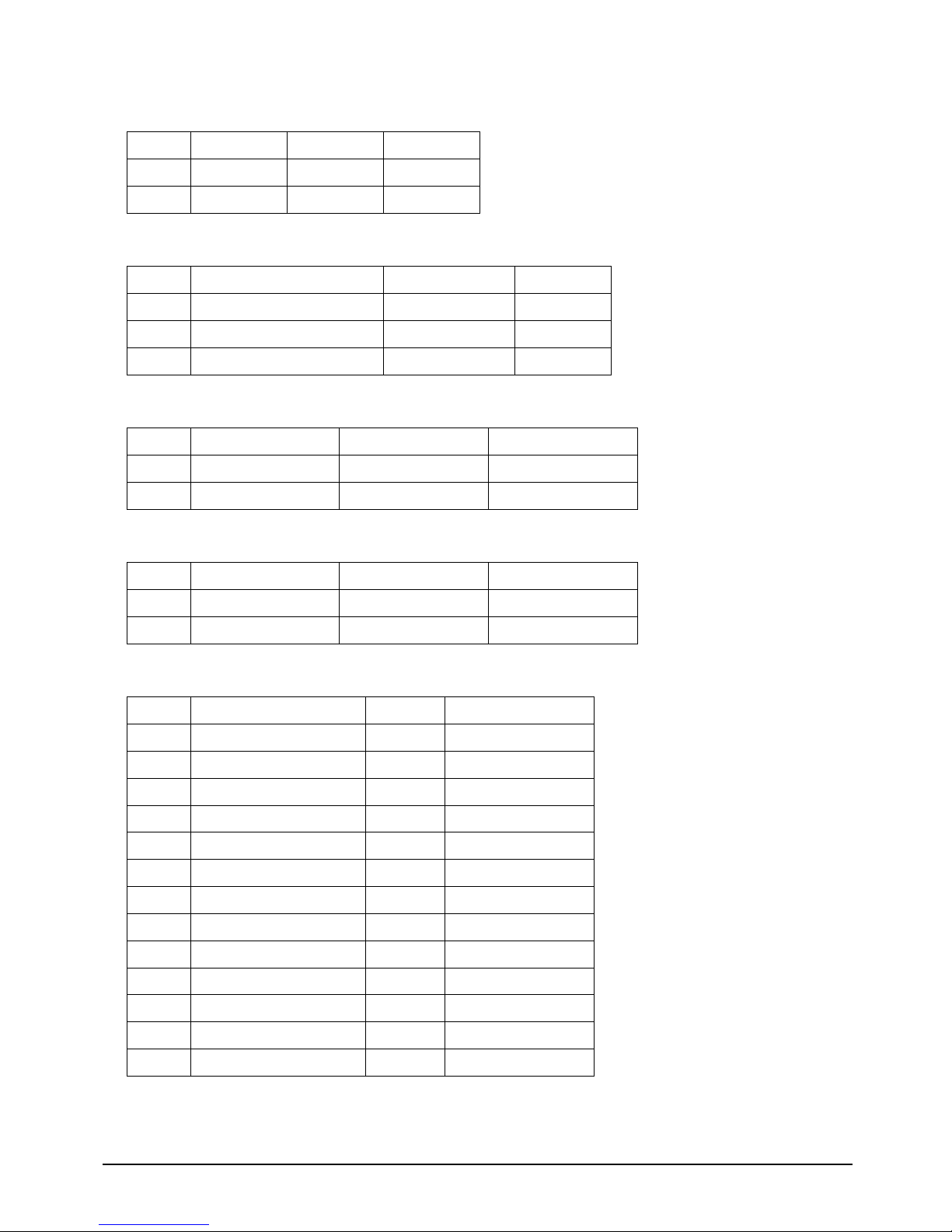
◎JP6(Thermister):Pin header 1x2 2.54mm Male 180-degree connector
◎JP10(Second COM port RI# function select):Pin header 1x3 2.54mm Male 180-degree connector
Pin NO. Description Pin NO. Description
1-2 +12V 4-5 RI#
2-3 +5V
◎CON1(Power connector):1x6 3.96mm Male 180-degre e connector
Pin NO. Description Pin NO. Description
1 +12V 4 GND
2 GND 5 +5V
3 GND 6 +5V
◎FAN1(FAN):Pin header 1x3 2.54mm Male 180-degree connector
Pin NO. Description Pin NO. Description
1 GND 3 FAN speed sense
2 +12V
◎FAN2(FAN):Pin header 1x3 2.54mm Male 180-degree connector
Pin NO. Description Pin NO. Description
1 GND 3 FAN speed sense
2 +12V
◎CN1 (Parallel port):Box header 2x13 2.0mm 180-degree connector
Pin NO. Description Pin NO. Description
1 Strobe# 14 Auto form feed#
2 DATA0 15 Error#
3 DATA1 16 Initialize
4 DATA2 17 Printer select IN#
5 DATA3 18 Chassis GND
6 DATA4 19 Chassis GND
7 DATA5 20 Chassis GND
8 DATA6 21 Chassis GND
9 DATA7 22 Chassis GND
10 Acknowledge# 23 Chassis GND
11 Busy 24 Chassis GND
12 Paper empty 25 Chassis GND
13 Printer select 26 NA
Page 20
EBC 580 User’s Manual 19
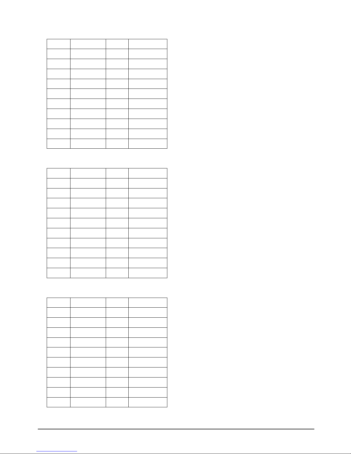
◎CN5 (LVDS1) (Slave)
Pin NO. Description Pin NO. Description
1 NA 2 NA
3 Panel Power 4 B0P
5 B3P 6 BOM
7 B3M 8 Panel Power
9 GND 10 B1P
11 CLK2P 12 B1M
13 CLK2M 14 GND
15 GND 16 +12V
17 B2P 18 +12V
19 B2M 20 GND
◎CN4 (LVDS1) (Master)
Pin NO. Description Pin NO. Description
1 NA 2 NA
3 Panel Power 4 A0P
5 A3P 6 AOM
7 A3M 8 Panel Power
9 GND 10 A1P
11 CLK1P 12 A1M
13 CLK1M 14 GND
15 GND 16 +12V
17 A2P 18 +12V
19 A2M 20 GND
◎CN2 (LVDS2) (Slave)
Pin NO. Description Pin NO. Description
1 NA 2 NA
3 Panel Power 4 DOB0P
5 DOB3P 6 DOBOM
7 DOB3M 8 Panel Power
9 GND 10 DOB1P
11 DOCLK2P 12 DOB1M
13 DOCLK2M 14 GND
15 GND 16 +12V
17 DOB2P 18 +12V
19 DOB2M 20 GND
Page 21
EBC 580 User’s Manual 20
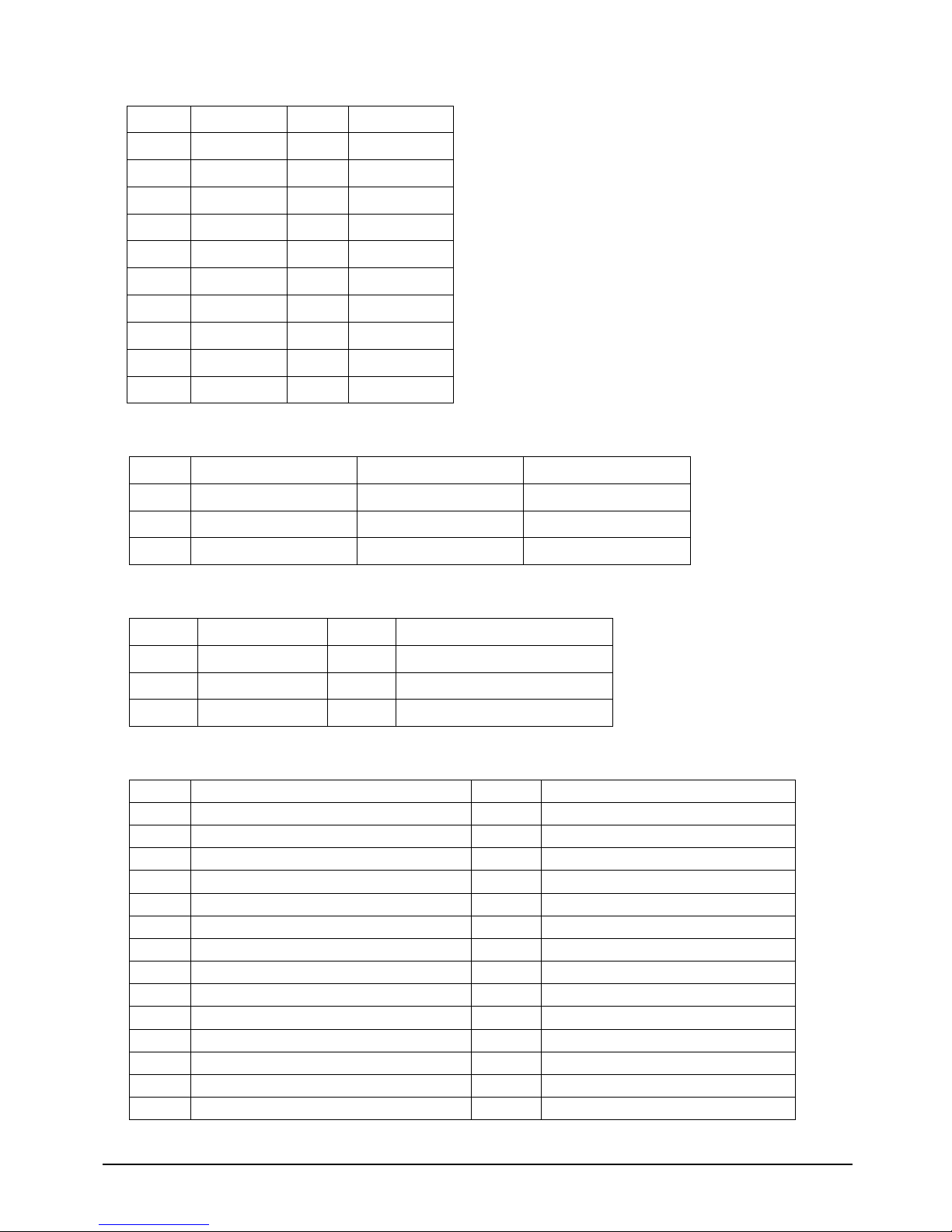
◎CN3 (LVDS2) (Master)
Pin NO. Description Pin NO. Description
1 NA 2 NA
3 Panel Power 4 DOA0P
5 DOA3P 6 DOAOM
7 DOA3M 8 Panel Power
9 GND 10 DOA1P
11 DOCLK1P 12 DOA1M
13 DOCLK1M 14 GND
15 GND 16 +12V
17 DOA2P 18 +12V
19 DOA2M 20 GND
◎CN12 (Line out)
Pin NO. Description Pin NO. Description
1 GND 4 NC
2 Right soun d channel 5 Left sound channel
3 NC
◎CN1 1 (Microphone Input)
Pin NO. Description Pin NO. Description
1 GND 4 NC
2 Microphone Input 5 Microphone BIAS
3 NC
◎CN9 (4 x COM):Box header 2x20 2.0mm connector
Pin NO. Description Pin NO. Description
1 Dat a ca rrie r dete ct A 2 Data set ready A
3 Re ceive data A 4 Request to send A
5 Transmit data A 6 Clear to send A
7 Data terminal ready A 8 Ring indicator A
9 GND 10 NC
1 1 Data carrier detect B (RS422/485 TX+) 12 Data set ready B (RS422 RTS-)
13 Receive data B (RS422/485 TX-) 14 Request to send B (RS422 RTS+)
15 Transmit data B (RS422 RX+) 16 Clear to send B (RS422 CTX+)
17 Data terminal ready B (RS422 RX-) 18 Ring indicator B (RS422 CTX-)
19 GND 20 NC
21 Data carrier detect C 22 Data set ready C
23 Receive data C 24 Request to send C
25 Transmit data C 26 Clear to send C
27 Data terminal ready C 28 Ring indicator C
Page 22
EBC 580 User’s Manual 21
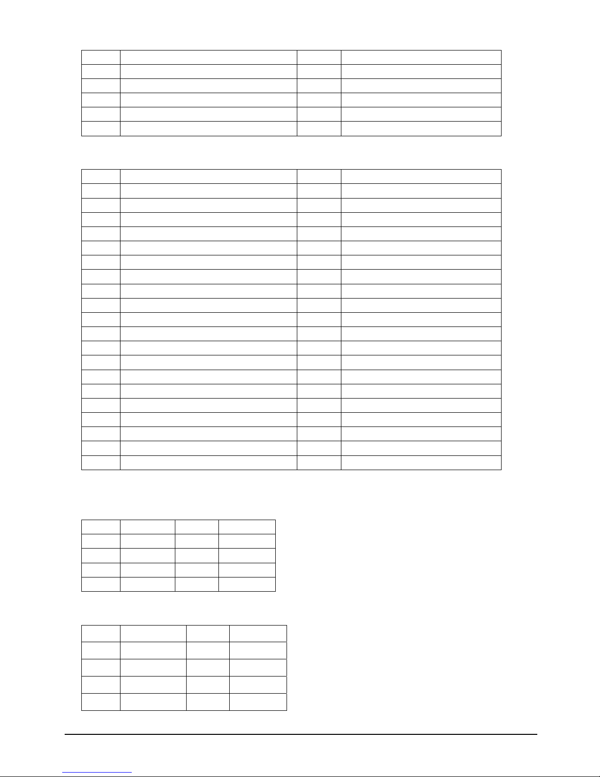
29 GND 30 NC
31 Data carrier detect D 32 Data set ready D
33 Receive data D 34 Request to send D
35 Transmit data D 36 Clear to send D
37 Data terminal ready D 38 Ring indicator D
39 GND 40 NC
◎CN7 (IDE):Box header 2x22 2.0mm connector
Pin NO. Description Pin NO. Description
1 RESET# 2 GND
3 DATA7 4 DATA8
5 DATA6 6 DATA9
7 DATA5 8 DATA10
9 DATA4 10 DATA11
11 DATA3 12 DATA12
13 DATA2 14 DATA13
15 DATA1 16 DATA14
17 DATA0 18 DATA15
19 GND 20 NC
21 DMA request 22 GND
23 IOW# 24 GND
25 IOR# 26 GND
27 IOCHRDY 28 Pull down
29 DMA Acknowledge# 30 GND
31 IRQ14 32 NC
33 Disk address1 34 DMA66 Detect
35 Disk address0 36 Disk address2
37 HDC CS1 38 HDC CS3
39 HD active LED 40 GND
◎CN6 (PCI)
◎CN8 (SATA1)
Pin NO. Description Pin NO. Description
1 GND 5 RX2 TX+ 6 RX+
3 TX- 7 GND
4 GND
◎CN10 (SATA2)
Pin NO. Description Pin NO. Description
1 GND 5 RX2 TX+ 6 RX+
3 TX- 7 GND
4 GND
Page 23
EBC 580 User’s Manual 22
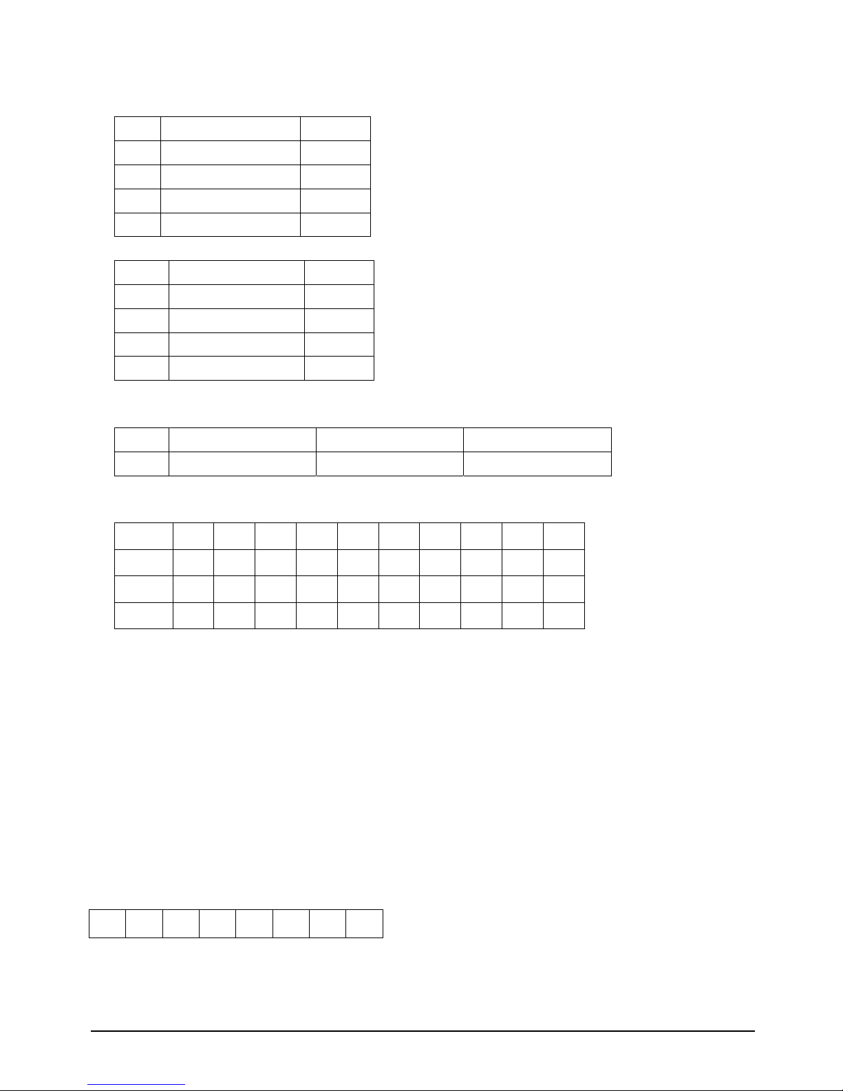
◎DIMM1 (DDR Socket)
◎GPIO ( Super I/O:W83697UF ).
Input
W83697UF pin name Pin number
TIN0 GP17 121
TIN1 GP16 122
TIN2 GP15 123
TIN3 GP14 124
Output
W83697UF pin name Pin number
TOUT0 GP13 125
TOUT1 GP12 126
TOUT2 GP11 127
TOUT3 GP10 128
◎ JP19 (Power LED)
Pin NO. Description Pin NO. Description
1 +5V 2 GND
◎ SW1 (COM2 Mode Select)
NO. 1 2 3 4 5 6 7 8 9 10
RS 232 OFF OFF OFF ON OFF ON OFF OFF OFF OFF
RS 422 OFF OFF ON OFF ON OFF ON ON ON ON
RS 232 OFF OFF OFF ON OFF ON OFF OFF OFF OFF
◎GPIO Programming guide:
Logical Device 7
CRF0 (GP10-GP17 I/O selection register. Default 0xFF)
When set to a ’1’, the respective GPIO port is programmed as an input port. ?
When set to a ’0’, the respective GPIO port is programmed as an output port. ?
CRF1 (GP10-GP17 data register. Default 0x00)
If a port is programmed to be an output port, its respective bit can be read/written.
If a port is programmed to be an input port, its respective bit can only be read.
CRF2 (GP10-GP17 inversion register. Default 0x00)
When set to a ‘1’, the incoming/outgoing port value is inverted.
When set to a ‘0’, the incoming/outgoing port value is the same as in the data register.
14 15 16 17 10 11 12 13
SIO_PORT EQU 2EH
SIO_ENTRY EQU 087H
SIO_EXIT EQU 0AAH
Page 24

EBC 580 User’s Manual 23
SIO entry configuration procedure
mov dx,SIO_PORT
mov al,SIO_ENTERY
out dx,al
nop
nop
out dx,al
Logical Device 7
mov dx,SIO_PORT
mov al,07h
out dx,al ;point to logical device number register
;
mov al,07h
inc dl
out dx,al ;select logical device 7
Reading Digit I/O data for register CRF1
mov dx,SIO_PORT
mov al,0F1h
out dx,al
inc dl
in al,dx ;You need data in AL register
SIO exit configuration procedure
mov dx,SIO_PORT
mov al,SIO_EXIT
out dx,al
◎ Watch Dog timer programming guide
WDT_CRWM EQU 0F3H
Logical Device 8
CRF3 (PLED mode register. Default 0x00)
Bit [7:3]:Reserved .
Bit 2:Select WDTO count mode.
0-Second
1-Minute
Bit [1:0]:select PLED mode
00 Power LED pin is tri-stated.
01 Power LED pin is droved low.
10 Power LED pin is a 1Hz toggle pulse with 50 duty cycle.
11 Power LED pin is a 1/4Hz toggle pulse with 50 duty cycle.
WDT_CRWV EQU 0F4H
Logical Device 8
CRF4 (Default 0x00)
Watch Dog Timer Time-out value.
Writing a non-zero value to this register causes the counter to load the value to Watch Dog Counter and
start counting down.
Reading this register returns current value in Watch Dog Counter instead of Watch Do g Timer
Time-out value.
Bit [7:0] = 0x00 Time-out Disable
= 0x01 Time-out occurs after 1 second/minute
= 0x02 Time-out occurs after 2 second/minutes
= 0x03 Time-out occurs after 3 second/minutes
.....................................................................................
= 0xFF Time-out occurs after 255 second/minutes
WDT_CRWE EQU 0F5H
Logical Device 8
Page 25

EBC 580 User’s Manual 24
CRF5 (Default 0x00)
Bit [7]:Reserved .
Bit [6]:invert Watch Dog Timer Status
Bit [5]:Force Watch Dog Timer Time-out, Write only*
1- Force Watch Dog Timer time-out event;this bit is self-clearing.
Bit[4]:Watch Dog Timer Status, R/W
1- Watch Dog Timer time-out occurred.
Bit [3:0]:These bits select IRQ resource for Watch Dog.
Setting of 2 selects SMI.
SIO entry configuration procedure
mov dx,SIO_PORT
mov al,SIO_ENTERY
out dx,al
nop
nop
out dx,al
Watch Dog setting
Logical Device 8
mov dx,SIO_PORT
mov al,07h
out dx,al ;point to logical device number register
mov al,08h
inc dl
out dx,al ;select logical device 8
Set units are seconds
mov dx,SIO_PORT
mov al,WDT_CRWM
out dx,al
inc dl
in al,dx
and al,not 04h
mov ah,al
mov dx,SIO_PORT
mov al,WDT_CRWM
out dx,al
inc dl
mov al,ah
out dx,al
Set time out value
mov dx,SIO_PORT
mov al,WDT_CRWV
out dx,al
inc dl
mov al,WDT_TIME_OUT
out dx,al
Set timer to be reset upon mouse or keyboard interrupt
mov dx,SIO_PORT
mov al,WDT_CRWE
out dx,al
inc dl
mov al,10h ;Watch Dog Timer Status, R/W:set "1"
out dx,al
SIO exit configuration procedure
mov dx,SIO_PORT
mov al,SIO_EXIT
out dx,al
Page 26

EBC 580 User’s Manual 25
Chapter 3
Expansion
Page 27
EBC 580 User’s Manual 26
3.1 System Memory
EBC 580 incorporates VIA CN700chipset supports up to 1GB un-buffered non-ECC DDR 333/400
SDRAM.
3.2 Installing DIMM
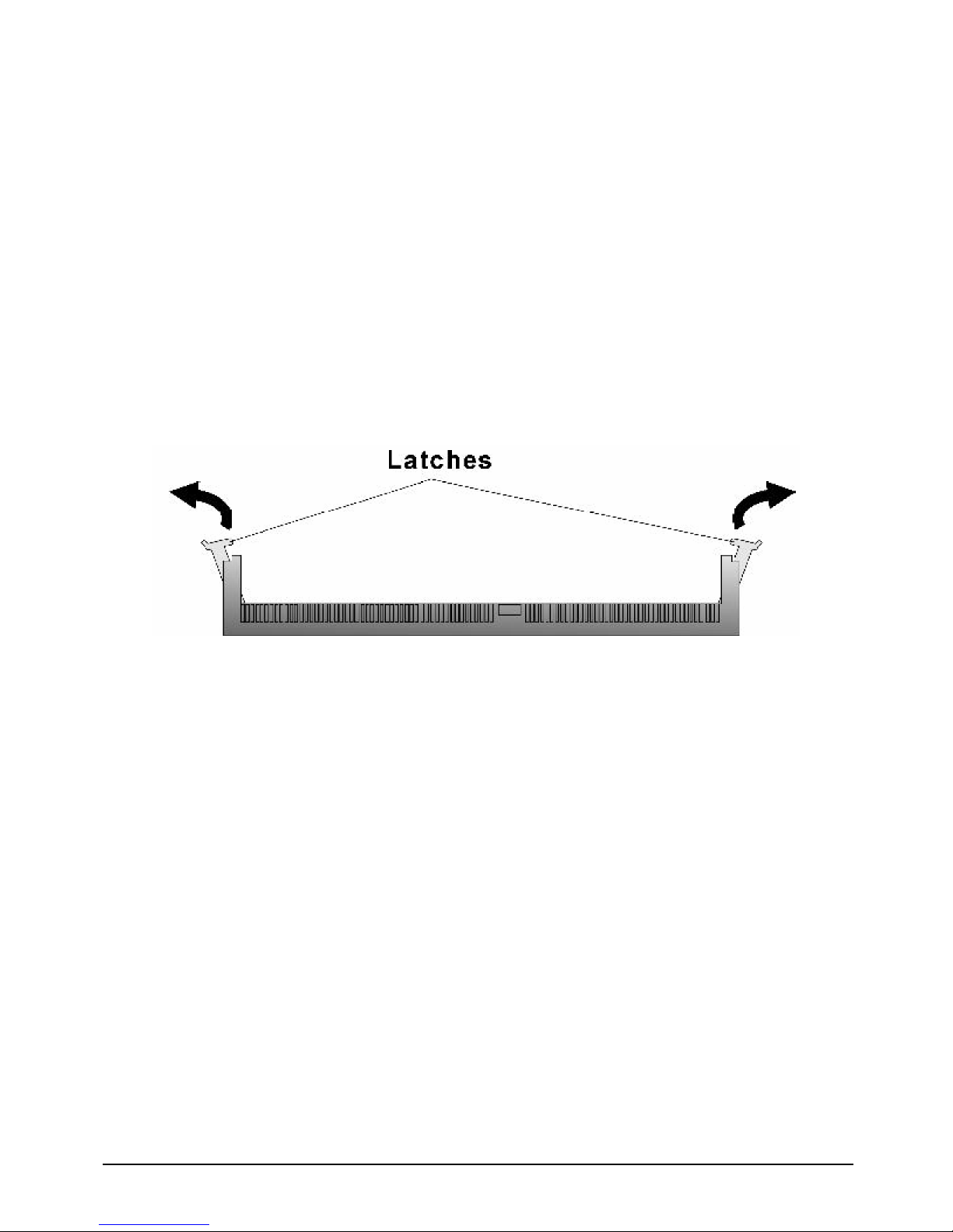
To install DIMM
1. Make sure the two handles of the DIMM sockets are in the “open” position, i.e. the handles stay
outward.
Figure3-1: How to Install DIMM (1)
Page 28
EBC 580 User’s Manual 27
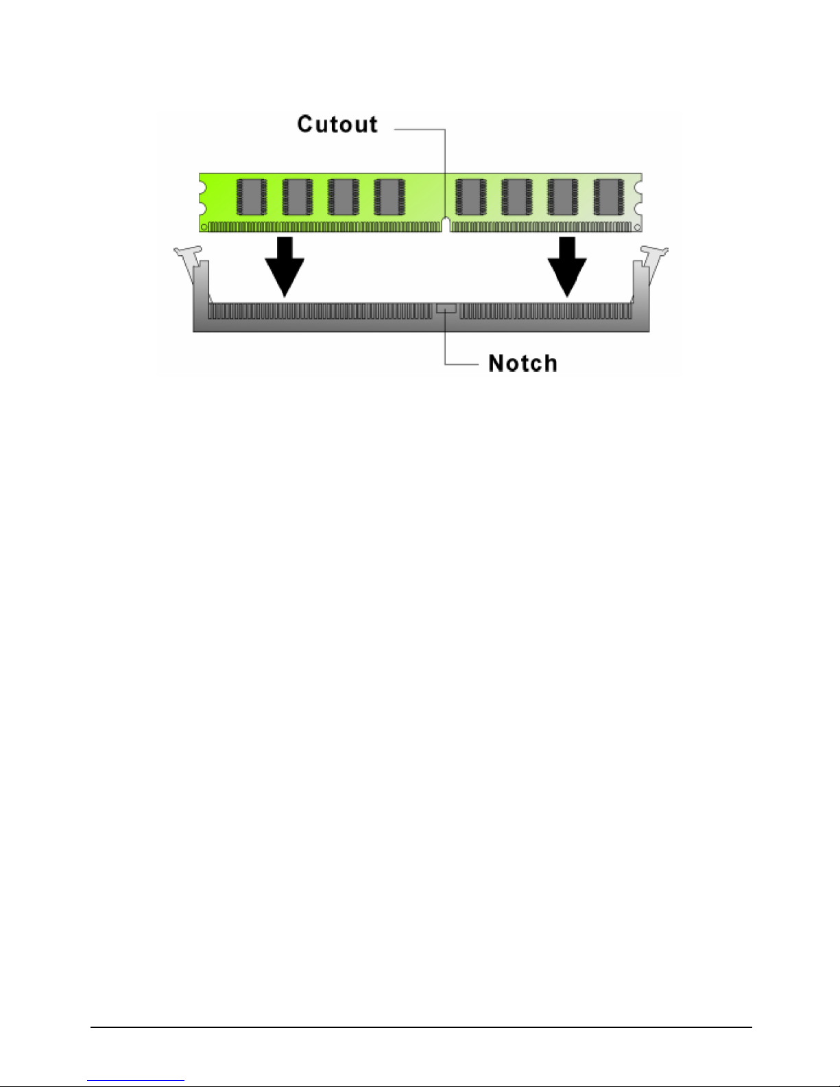
2. Slowly slide the DIMM modules along the plastic guides in the both ends of the socket.
Figure 3-2: How to Install DIMM (2)
Page 29
EBC 580 User’s Manual 28
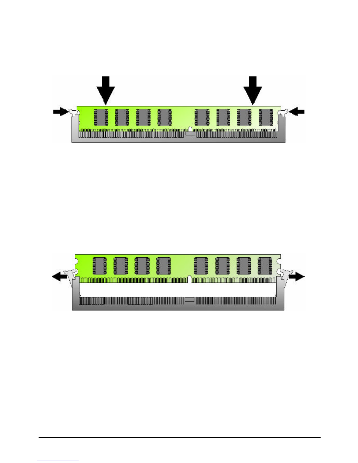
3. Then press the DIMM module down right into the socket, until a click is heard. That means the two
handles automatically locked the memory modules into the right position of the DIMM socket.
Figure 3-3: How to Install DIMM (3)
4. To take away the memory module, just push the both handles outward, the memory module will be
ejected by the mechanism in the socket.
Figure 3-4: How to Install DIMM (4)
Page 30
EBC 580 User’s Manual 29
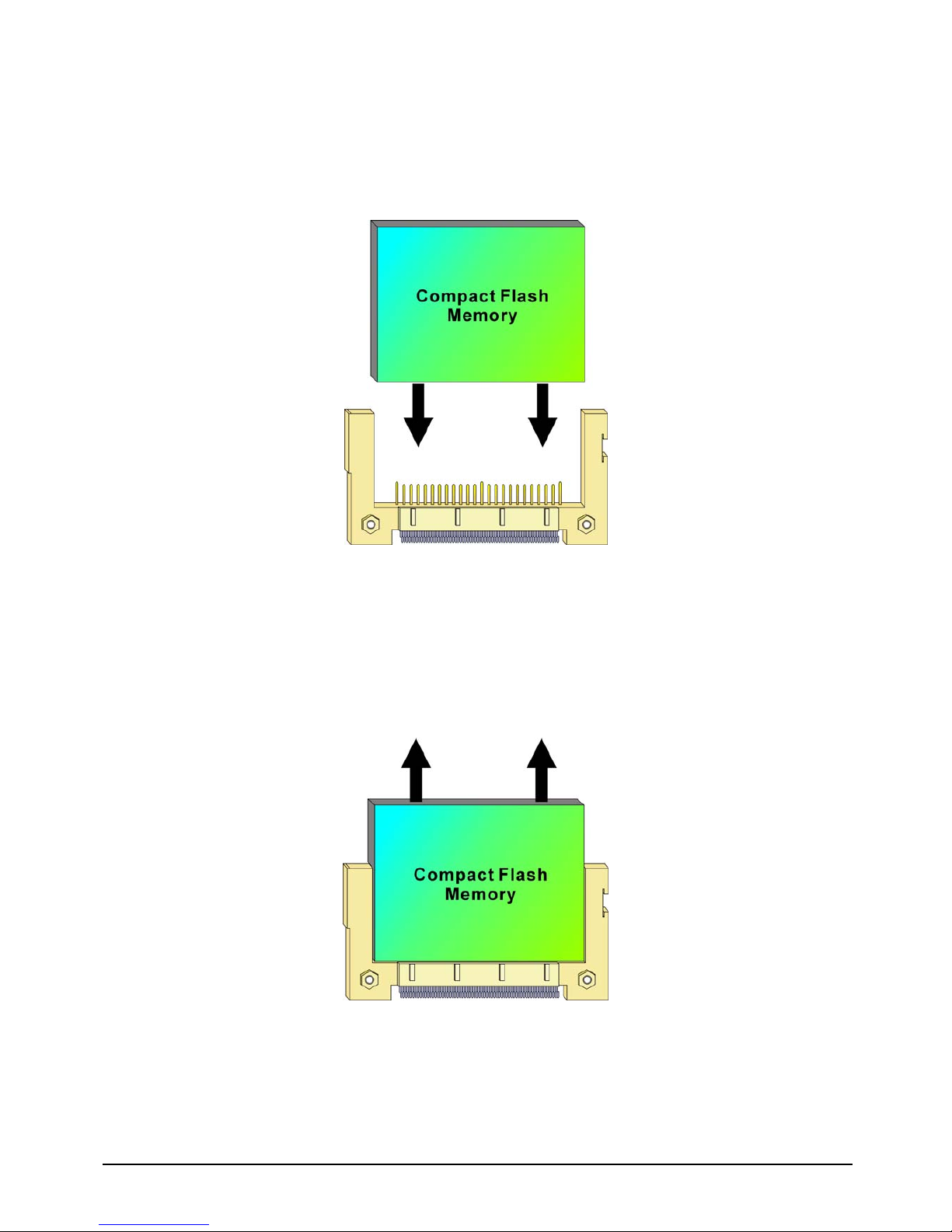
3.3 Installing Compact Flash
1. To install a Compact Flash memory card into EBC 580, align the notches on the card with the Compact
Flash socket in the EBC 580. Then firmly insert the card into the socket until it is completely seated.
Figure 3-5: How to Install Compact Flash Memory (1)
2. To remove the Compact Flash memory card from EBC 580, pull out the memory card from the
Compact Flash socket.
Figure 3-6: How to Uninstall Compact Flash Memory (2)
 Loading...