

Page 1
Nexgrill Industries ,Inc.
145, Brea Canyon Road
Walnut, CA 91789, U.S.A.
® ®
FOR MODEL T–005
TABLE OF CONTENTS Page
I PORTANT …………………………………………
M
TOOLS & PARTS………………………………………
PRECAUTIONS………………………………………..
ASSEMBLY INSTRUCTIONS ……………………….
GAS REQUIREMENTS & LEAK TESTING …………
LOCATING HEATER FOR USE ……………………...
LIGHTING INSTRUCTION……………………………. IGHTING INSTRUCTION…………………………….
SHUTDOWN INSTRUCTION………………………… SHUTDOWN INSTRUCTION…………………………
STORAGE & BURNER REMOVAL…………….……. STORAGE & BURNER REMOVAL…………….…….
TROUBLE SHOOTING ………………………………. TROUBLE SHOOTING ……………………………….
EXPLODED VIEW.…………………………………… EXPLODED VIEW.……………………………………
WARRANTY
WARRANTY
STOP
………………………………………….
………………………………………….
PLEASE CONTACT 1-800-913-8999 FOR ASSISTANCE
DO NOT RETURN TO PLACE OF PURCHASE
GAS-FIRED INFRARED
OUTDOOR PATIO HEATER
INSTALLATION, OPERATION
MAINTENANCE INSTRUCTIONS
1
2
3
4
7
8
9
10
11
12
13
14
Page 2
﹡﹡﹡IMPORTANT NOTICE:
DO NOT return to place of purchase!!!
Please contact Customer Service hotline at 800-913-8999 for help.
IMPORTANT
* * *
WARNING
* * *
For outdoor use only (outside any enclosure)
Improper operation, installation, adjustment, alteration,
servicing or maintenance can cause severe property
damage or serious injury or death. Please read the
installation, operation & maintenance instructions thoroughly
before installing or servicing this equipment.
* * *
FOR YOUR SAFETY
If you smell gas:
Shut off gas to appliance.
Extinguish any open flame.
If odor continues, immediately call your gas supplier.
* * *
For your safety:
Do not store or use gasoline or other flammable vapor and
liquids in the vicinity of this or any other appliance.
Page 1
Page 3

TOOLS AND PARTS NEEDED FOR ASSEMBLY
NOTE: Propane Gas Tank is not supplied
Tools Needed:
Phillips Screwdriver
Spray Bottle Of Soapy Water (To Check For Leaks)
Parts Supplied:
Base Assembly with T ank Cover
Post & Burner Assembly
Emitter Assembly
Emitter Screen (2)
Reflector
Reflector Dome Cap
Hardware Bag
Tank Enclosure 3/16” Screw (3)
Emitter Base 3/16” Screw (3)
Emitter Screen 3/16” Screw (4)
Reflector cap nut (1pc)
For Service Questions Replacement parts or other Assistance, Please call
VAI Customer Service Hotline at:
VAI
145 Brea Canyon Road
Walnut, CA 91789
(800)913-8999
Page 2
Page 4

r
r
PRECAUTION
Do not use this space heater in an explosive atmosphere. Keep heater away from areas where
gasoline or other flammable liquids or vapors are stored.
Do not attempt to alter unit in any manner. EXAMPLE: using the heater without the top canopy
reflector or radiant screen. Do not shorten the burner post assembly.
Heater must always be placed on a solid and level surface.
Always ensure there is ample fresh air ventilation for outdoors use ONLY.
Never replace or substitute the regulator with any regulator other than the factory suggested
replacement.
Do not paint radiant screen, control panel or top canopy reflector.
All leak test should be done with a soapy solution.
LEAKS.
At least once a year the unit should be inspected for the presence of spider, spider web or othe
insects haven and can damage the heater and render it unsafe for use,
Check the heater immediately if any of the following exists:
1. T h e s m e l l o f g a s i n c o n j u nc t i o n w i t h extreme yellow tipping of the burner flames.
2. The heater does not reach temperature.
3. The burner makes popping noise during use (a slight popping noise is normal when the burner is
extinguished).
Children and adults should be aware of hazards of high surface temperature and shall stay away to
avoid burns of clothing ignition.
Young children should be carefully supervised when they are in the area of the heater.
Clothing or other flammable material should not be hung from the heater, or placed on or near the
heater.
Repair and services should be done by a qualified service person, the heater must be inspected
before use and at least annually by a qualified service person. More frequent cleaning may be
required as necessary. It is imperative that control compartment, burner and circulating ai
passageways of the heater be kept clean.
Keep the appliance area clear and free of combustion material.
Do not obstruct the flow of combustion and ventilation air.
Keep the ventilation opening of the cylinder enclosure free and clear of debris.
.
NEVER USE AN OPEN FLAME TO CHECK FOR
Page 3
Page 5
r
r
t
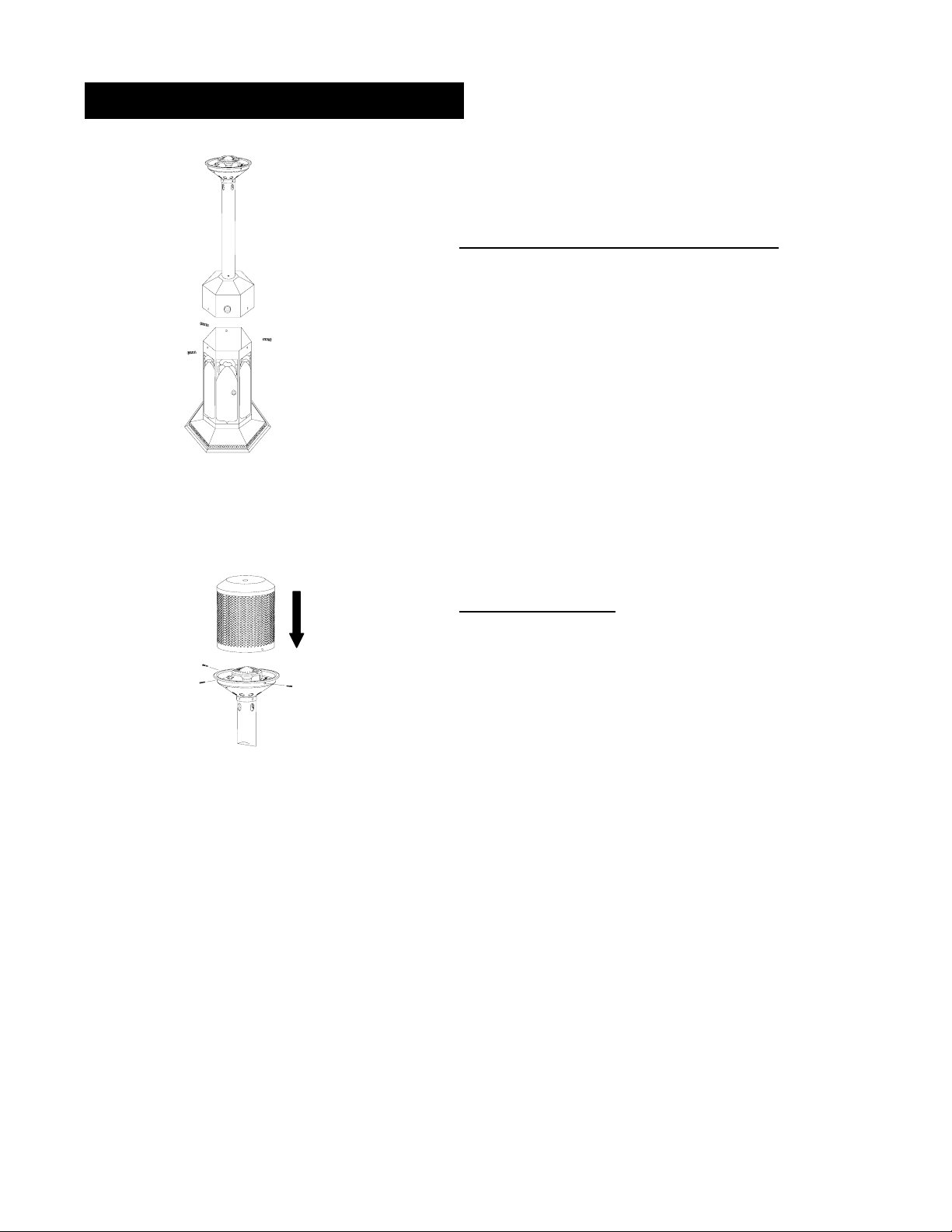
ASSEMBLY INSTRUCTION
STEP 1: Connect Top Portion to Tank Enclosure
Place top portion on of tank enclosure. Inser
the three 3/16” truss head screws in three holes
until tight.
STEP 2:
Attach Emitter Grid
Line up three holes on bottom of Emitte
Grid with corresponding holes in emitte
bottom, fasten three 3/16"truss head
screws to the emitter base.
Page 4
Page 6

f
ASSEMBLY INSTRUCTION
.
STEP 3: Attach Emitter Screen
a. Attach one piece emitter screen with two truss
head 3/16" screws to the post.
b. Hook up two emitter screen together.
c. Screw the other emitter screen on post with two
truss head 3/16” screws.
STEP 4: Attach the Reflector
Insert threaded end of final cap nut
through cap and screw into center o
dome until secure.
Page 5
Page 7

ASSEMBLY INSTRUCTION
STEP 5:
Make sure gas control knob is in “OFF” position.
Open the tank enclosure door to locate the regulator.
Rotate gas pressure regulator outwards.
Attach propane gas to regulator inlet fitting by turning the propane gas clockwise.
The LP-Gas supply cylinder must be disconnected when this appliance is not in use.
Disconnect it by turning the propane gas counter-clockwise.
Cylinder Attachment To Heater
Page 6
Page 8

GAS REQUIREMENTS & LEAK TESTING
/
Gas Requirements
The gas pressure regulator provided with this heat er must be used. This regulator is set for L.P
Propane units at 10.0” W.C.
Maximum inlet pressure to propane regulator must not exceed 100 PSI.
The pressure regulator provided with this heater must be used. This regulator is set for L.P.
Propane units at 10.0” W.C.
The propane tank must be constructed and marked in accordance with the specifications for LP gas
cylinders of the US Department of Transportation.
A dented, rusted or damaged propane tank may be hazardous and should be checked by your tank
supplier. Never use a gas tank with a damaged valve connection.
Leak Testing
Make a soap solution of one part liquid detergent and one part water. The solution can be
applied with a spray bottle, brush or rag. Soap bubbles will appear where a leak is present.
Once the gas cylinder is securely attached make certain the control valve knob is in the ‘OFF’
position then check for leaks.
If a leak is present detach the gas cylinder, tighten any leaking fitting, re-attached the gas
cylinder and recheck.
Warning: Never connect an unregulated gas supply to the heater.
!
Page 7
Page 9

LOCATING HEATER FOR USE
Be Careful: When certain materials or items are left under this heater while in use, they will be subjected to
radiant heat and could be seriously damaged.
CEILING/OVERHANG
12"
12"
WALL
The heater is primarily for heating of outdoor patios, decks, spas, pool and working areas.
The minimum clearances to combustible construction shown in above must be maintained at all times
The installation must conform to local codes or in the absence of local codes with the sta ndard for the
storage and handling of liquid petroleum gases:
In the US use : ANSI/NFPA58 on National Fuel Gas Code ANSI Z223-1998
In Canada use: National Standards of Canada. CAN/CGA B149.1 & 2-M86
Page 8
Page 10

LIGHTING INSTRUCTION
BEFORE TURNING ON THE GAS SUPPLY:
Be sure all gas connections are tight and there are no leaks.
Make sure surrounding areas are free of combustible materials, gasoline, and other flammable
vapors or liquids.
BEFORE RE-LIGHTING:
For your safety, if re-lighting a hot heater, always wait at least five (5) minutes.
NOTE: 16.4 oz Propane tank must be used
TO LIGHT:
(A) Open tank enclosure door.
(B) Make certain regulator is connected to the gas tank. Check the connection to ensure they are tight and
leak proof.
(C) Check for leaks by applying soapy water to the tank and regulator connections.
(D) Push and turn the gas control knob to ‘HIGH’ postion for several seconds. It might take 2 or 3 trials to
light the burner.
Warning: Keep a safe distance of at least 3 feet when attampting to ignite unit.
!
Avoid inhaling fumes emitted from the heater’s first use. Smoke and odor from the burning
"
of oils used in manufacturing will appear. Both smoke and odor will dissipate after
approximately 30 minutes. The heater should NOT produce thick black smoke.
Page 9
Page 11

SHUTDOWN INSTRUCTION
WHEN HEATER IS ON:
Emitter grid will become brighter due to intense heat. The color is more visible at night.
Burner will display tones of blue and yellow flame. These flames should not be yellow or produce thick
black smoke, indicating an obstruction of airflow through the burners. The flame should be blue with
straight yellow tips.
The flame pattern at the emitter grid should be visually checked whenever heater is opereted (see figure
2). If flames extend more than 1/2 inch beyond surface of the emitter grid or reflector the heater should
be turned off immediately and the heater should not be operated again until repairs are made.
FIGURE 2
NORMAL FLAME POSITION
RELIGHTING
(A) Turn the control knob to off position.
(B) Wait five (5) minutes before attempting to relight burner.
(C) Repeat “To Light” Step (D) on prior page.
SHUT DOWN INSTRUCTIONS:
(A) Turn control knob clockwise to ‘OFF’ position. The burner may make a slight popping sound when
extinguished. This is normal.
(B) Turn control knob clockwise to ‘OFF’ position when heater is not in use
This Heater contains the Tilt Safety Switch which is designed to provide safe use of the patio heater.
!
The tilt safety switch will automatically shut-off the heater when it tilts in the trip angle over 45-60
degrees from vertical position.
2"
1"
0
"
Page 10
Page 12

Page 13

TROUBLE SHOOTING
Problem Possible Causes Correction
Pilot won’t
light
Pilot won’t
stay lit
Main burner
won’t light
Air in gas line
Low gas pressure
Blockage in gas line
Tilt switch in trip angle/OFF position
Bad thermocouple
Corrosion of thermocouple contact
Safety interlock is triggered
Bad gas valve
Thermocouple connection loose at gas
control or damaged
Pilot flame not touching the
thermocouple
Low gas pressure
Blockage in burner
Control knob not in ‘HIGH’ position
Purge gas line and repeat ignition operation
Check gas pressure
Check gas passage way
Reset the Heater keep in vertical position
Replace thermocouple
Clean thermocouple contact
Wait a minute repeat ignition operation
Replace gas valve
Tighten connection or replace thermocouple
Contact a qualified service person
Check gas supply pressure
Clean burner inside and outside
Turn control knob to ‘HIGH’ position
Page 12
Page 14

EXPLODED VIEW
1
2
PARTS LIST
10
11
18
19
20
3
4
5
6
7
8
…
9
12
13
16
14
15
17
21
22
23
24
NO.
1
2
3
4
5
6
7
8
9
10
11
12
13
14
15
16
17
18
19
20
21
22
23
24
DESCRIPTIO
REFLECTOR CAP NUT
DOME CAP
REFLECTOR
EMITTER GRID
MAIN BURNER ASSEMBLY
EMITTER BASE
EMITTER SCREEN
3/16’’ TRUSS HEAD SCREW
POST
ORIFICE
GAS PIPE
3/16’’SCREW
SHROUD COVER
PILOT ASSEMBL Y
GAS VALVE CONTROL
REGULATOR
TILT SAETY SWITCH
VA LVE KNOB
CYLINDER HOUSING DOOR
DOOR LATCH
CYLINDER HOUSING PANEL
BASE ASSEMBLY
RUBBER BAND
WEIGHTED BASE
Q’TY
1
1
1
1
1
1
2
17
1
1
1
7
1
1
1
1
1
1
1
1
1
1
1
Page 13
Page 15

LIMITED WARRANTY
FOR T – 005
GAS-FIRED INFRARED OUTDOOR PATIO HEATER
Nexgrill Industries , Inc. warrants to the original consumer purchaser of each Outdoor Patio Heater that when
subject to normal residential use, it is free from defects in workmanship and materials under normal conditions
of use in a commercial application for a period of 90 days from purchase and in a residential application for a
period of 1 year. Any work or repair of the heater must be performed by qualified service personal. There
will be a shipping and handling charge for the delivery of the warranty part(s).
Component Warranty Period
Burner : 3 Years
Valve : : 1 Year
Pilot Kit : 1 Year
All Other Parts: 1 Year
Our obligation under this warranty is limited to repair or replacement at our option of the product during the
warranty period. The extent of any liability of Nexgrill Industries , Inc. under this warranty is limited to repair or
replacement. This warranty does not cover normal wear of parts, damage resulting from any of the following:
negligent use or misuse of the product, use on improper fuel/gas supply, use contrary to operating instructions,
or alteration by any person other than our factory service center. The warranty period is not extended by
such repair or replacement.
Warranty claim procedure: If you require service or parts for your Mini Table-Top Heater, please contact
our Warranty Service Center for factory direct assistance. Our hours of operation are 8 AM to 5 PM PST. Our
number is 1-800-913-8999 and our FAX number is 1-909-598-7699. Please direct all correspondence to:
Nexgrill Industries, Inc. 145 Brea Canyon Road, Walnut, CA 91789 ATTN: Warranty Service Center.
Product repair as provided under this warranty is your exclusive remedy. Nexgrill Industries ,Inc.shall not be
liable for any incidental or consequential damages for breach of any express or implied warranty on its
products. Except to the extent prohibited by applicable law, any implied warranty or merchantability or
fitness for a particular purpose on this product to the duration of the above warranty. Some states do not
allow the exclusion or limitation of incidental or consequential damages or allow limitations on how long an
implied warranty lasts, so the above limitations or exclusions may not apply to you. This warranty gives you
specific legal rights, and you may have other rights which vary from state to state.
Page 14
 Loading...