

New Yorker Boiler CI-HGS Installation Manual
INSTALLATION, OPERATING AND
SERVICE INSTRUCTIONS FOR
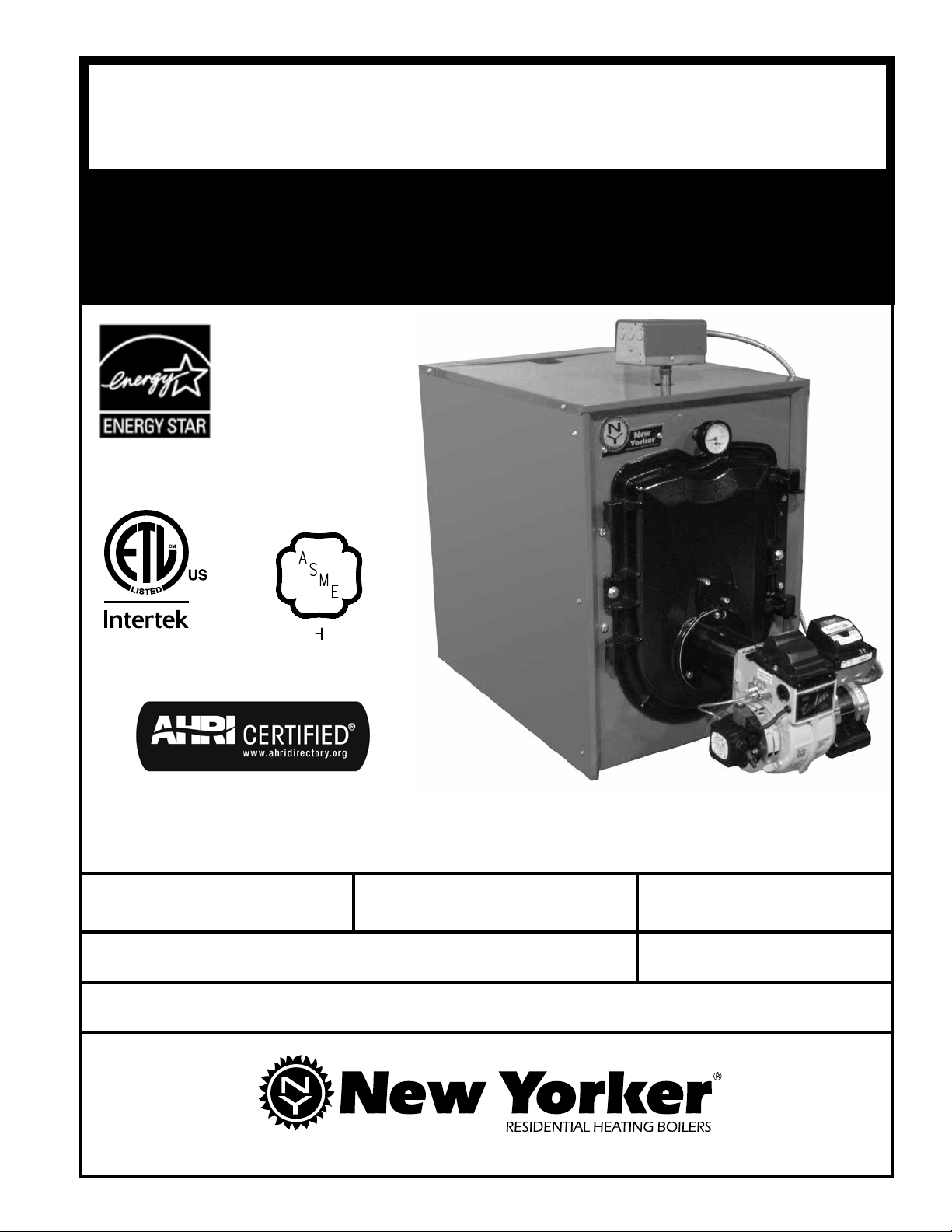
CI-HGS™-B SERIES
3-PASS OIL BOILER
9700609
As an ENERGY STAR
Partner, New Yorker Boiler
Co. Inc. has determined
that the CI-HGS™-B Series
meets the ENERGY STAR
guidelines for energy
efciency established by the
United States Environmental
Protection Agency (EPA).
®
®
For service or repairs to boiler, call your heating contractor or oil supplier. When seeking
information on boiler, provide Boiler Model Number and Serial Number as shown on Rating
Label located on top of the boiler.
Boiler Model Number
CI-HGS - _ _ _ B
Heating Contractor Phone Number
Address
105753-02 - 1/16
Boiler Serial Number Installation Date
Price - $5.00
IMPORTANT INFORMATION - READ CAREFULLY
All boilers must be installed in accordance with National, State and Local Plumbing, Heating
and Electrical Codes and the regulations of the serving utilities. These Codes and Regulations
may differ from this instruction manual. Authorities having jurisdiction should be consulted
before installations are made.
In all cases, reference should be made to the following Standards:
USA BOILERS
A. Current Edition of American National Standard ANSI/NFPA 31, “Installation of Oil
Burning Equipment”, for recommended installation practices.
B. Current Edition of American National Standard ANSI/NFPA 211, “Chimneys, Fireplaces,
Vents, and Solid Fuel Burning Appliances”, For Venting requirements.
C. Current Edition of American Society of Mechanical Engineers ASME CSD-1, “Controls and
Safety Devices for Automatically Fired Boilers”, for assembly and operations of controls
and safety devices.
D. All wiring on boilers installed in the USA shall be made in accordance with the National
Electrical Code and/or Local Regulations.
The following terms are used throughout this manual to bring attention to the presence of hazards
of various risk levels, or to important information concerning product life.
DANGER
Indicates an imminently hazardous situation
which, if not avoided, will result in death, serious
injury or substantial property damage.
WARNING
Indicates a potentially hazardous situation which,
if not avoided, could result in death, serious injury
or substantial property damage.
Indicates a potentially hazardous situation which,
if not avoided, may result in moderate or minor
injury or property damage.
Indicates special instructions on installation,
operation, or maintenance which are important
but not related to personal injury hazards.
CAUTION
NOTICE
NOTICE
This boiler has a limited warranty, a copy of which is printed on the back of this manual.
The warranty for this boiler is valid only if the boiler has been installed, maintained and operated in
accordance with these instructions.
Surface rust on cast iron sections may be attributed to the manufacturing process as well as condensation
during storage. Surface rust is normal and does not affect the performance or longevity of a boiler.
2
DANGER
DO NOT store or use gasoline or other ammable vapors or liquids in the vicinity of this or any other
appliance.
WARNING
Improper installation, adjustment, alteration, service or maintenance can cause property damage, personal
injury or loss of life. Failure to follow all instructions in the proper order can cause personal injury or
death. Read and understand all instructions, including all those contained in component manufacturers
manuals which are provided with the appliance before installing, starting-up, operating, maintaining or
servicing this appliance. Keep this manual and literature in legible condition and posted near appliance
for reference by owner and service technician.
This boiler requires regular maintenance and service to operate safely. Follow the instructions contained
in this manual.
Installation, maintenance, and service must be performed only by an experienced, skilled and knowledgeable
installer or service agency.
All heating systems should be designed by competent contractors and only persons knowledgeable in
the layout and installation of hydronic heating systems should attempt installation of any boiler.
Installation is NOT complete unless a pressure relief valve is installed into the 3/4" tapping located on
return piping that was installed into boss on top of rear section - See "Packaged Boiler Assy - Trim &
Controls" and "Water Boiler Piping" Sections of this manual for details.
It is the responsibility of the installing contractor to see that all controls are correctly installed and are
operating properly when the installation is complete including verifying that the limit sensor is fully
installed.
Failure to properly install Limit Sensor may result in property damage, personal injury or loss of life
due to elevated operating temperatures and/or pressures.
This boiler is suitable for installation on combustible ooring. DO NOT install boiler on carpeting.
DO NOT tamper with or alter the boiler or controls.
Inspect ueways at least once a year - preferably at the start of the heating season. The inside of
the combustion chamber, the vent system and boiler ueways should be cleaned if soot or scale has
accumulated.
When cleaning this boiler, take precaution to avoid damage to burner swing door insulation. If damaged,
or if there is evidence of previous damage, burner swing door insulation must be replaced immediately.
Oil Burner and Controls must be checked at least once a year or as may be necessitated.
DO NOT operate unit with jumpered or absent controls or safety devices.
DO NOT operate unit if any control, switch, component, or device has been subject to water.
Boiler materials of construction, products of combustion and the fuel contain alumina, silica, heavy metals,
carbon monoxide, nitrogen oxides, aldehydes and/or other toxic or harmful substances which can cause
death or serious injury and which are known to the state of California to cause cancer, birth defects and
other reproductive harm. Always use proper safety clothing, respirators and equipment when servicing
or working nearby the appliance.
3
WARNING
This boiler contains very hot water under high pressure. DO NOT unscrew any pipe ttings nor attempt
to disconnect any components of this boiler without positively assuring the water is cool and has no
pressure. Always wear protective clothing and equipment when installing, starting up or servicing this
boiler to prevent scald injuries. DO NOT rely on the pressure and temperature gauges to determine the
temperature and pressure of the boiler. This boiler contains components which become very hot when
the boiler is operating. DO NOT touch any components unless they are cool.
This boiler must be properly vented. The boiler must be connected to an approved chimney or vent
system in good condition. Serious property damage could result if the boiler is connected to a dirty or
inadequate chimney or vent system. The chimney must be inspected for any obstructions and cleaned
prior to each heating season. A clean and unobstructed chimney ue is necessary to produce the minimum
draft required to safely evacuate noxious fumes that could cause personal injury or loss of life. DO NOT
operate boiler with the absence of an approved vent system. Evidence of loose debris and or condensate
induced stains at the base of the chimney ue, connector or smokepipe joints may be signs of condensing
ue gases. Flue gas condensate is corrosive, which requires special consideration and must be addressed
immediately. Refer to "Natural Draft Venting (Chimney)" listed in Table of Contents below .
This boiler needs fresh air for safe operation and must be installed so there are provisions for adequate
combustion and ventilation air.
This boiler is supplied with controls which may cause the boiler to shut down and not re-start without
service. If damage due to frozen pipes is a possibility, the heating system should not be left unattended in
cold weather; or appropriate safeguards and alarms should be installed on the heating system to prevent
damage if the boiler is inoperative.
This boiler is designed to burn No. 2 fuel oil only. DO NOT use gasoline, crankcase drainings, or any
oil containing gasoline. Never burn garbage or paper in this boiler. DO NOT convert to any solid fuel
(i.e. wood, coal). DO NOT convert to any gaseous fuel (i.e. natural gas, LP). All ammable debris, rags,
paper, wood scraps, etc., should be kept clear of the boiler at all times. Keep the boiler area clean and
free of re hazards.
All boilers equipped with burner swing door have a potential hazard which, if ignored, can cause severe
property damage, personal injury or loss of life. Before opening swing door turn off service switch to
boiler to prevent accidental ring of burner outside the combustion chamber. Be sure to tighten swing
door fasteners completely when service is completed.
TABLE OF CONTENTS
I. General Information.......................................... 5 XI. Operating........................................................... 49
II. Pre-Installation ................................................ 7 XII. Maintenance & Service Instructions ................ 53
III. Packaged Boiler Assy. - Trim & Controls ......... 10 XIII. Boiler Cleaning ................................................ 55
IV. Water Boiler Piping .......................................... 19 XIV. Trouble Shooting ............................................. 58
V. Indirect Water Heater Piping ........................... 23 X V. Repair Parts .................................................... 61
VI. Natural Draft Venting (Chimney) ..................... 24
VII. Direct Venting / Air Intake Piping...................... 28
VIII. Electrical .......................................................... 35
IX. Oil Piping ......................................................... 39
X. System Start-Up............................................... 41
4
Appendix A
Burner Specications........................................
Appendix B
Low Water Cut Off............................................
73
75
"
3
SMOKEBOX
PRESURE
VALVE
RELIEF
OUT COVER
CLEAN
TAPPING
8
21
DRAIN VALVE
"NPT SYSTEM
1
2
1
CONNECTION
"NPT SYSTEM RETURN
1
2
1
12" MIN
CLEARANCE
(SEE NOTE 1)
REAR SERVICE
4
3
5 "
CLEARANCE
FRONT SERVICE
(FLUEWAY CLEANING)
SMOKEBOX COLLAR
DIA.
COLLAR
SPANNER BAR W/
ADJUSTABLE LEGS
"
1
4
13
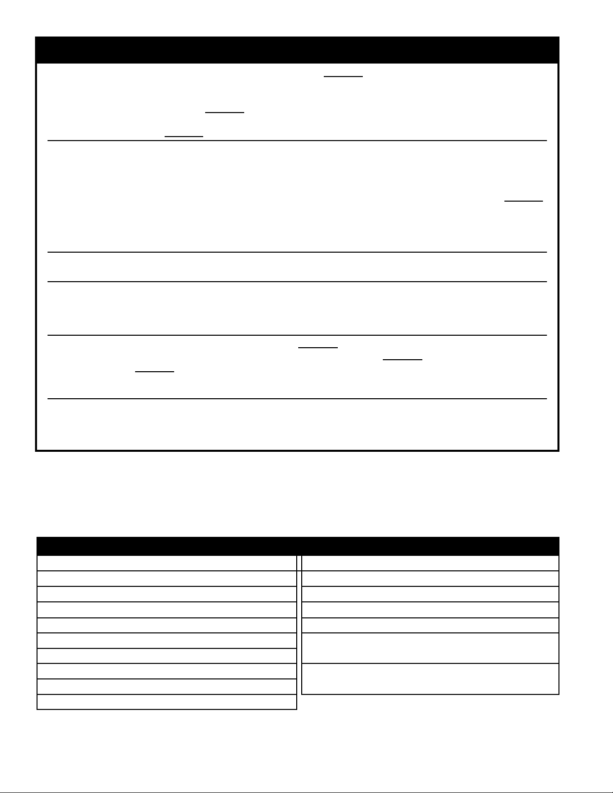
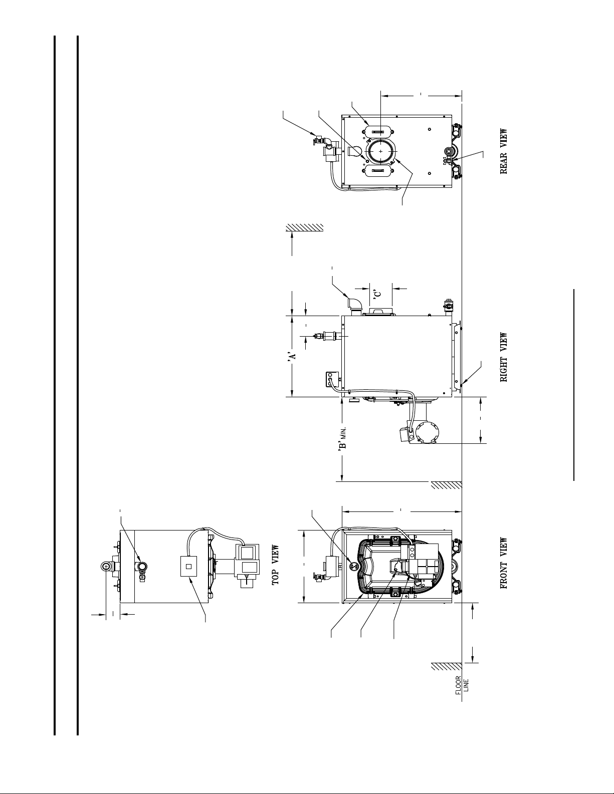
Figure 1: CI-HGS-74B thru CI-HGS-167B
GAUGE
SUPPLY
CONNECTION
TEMP/PRESSURE
"
3
8
31
SECTION I: GENERAL INFORMATION
4
3
20 "
"
11
16
3
BOILER
CONTROL
PORT
DOOR
FLAME
SWING
BURNER
OBSERVATION
BECKETT AFG
BURNER
(SHOWN)
19" MIN.
(SEE NOTE 3)
(FULLY OPEN)
BURNER SWING
DOOR CLEARANCE
1. THIS DIMENSION INCREASES AND IS CONTROLLED BY SMOKEPIPE ARRANGEMENT.
2. DRAIN VALVE AND RELIEF VALVE/FITTINGS SHIPPED LOOSE.
3. BOILER SHIPPED WITH STANDARD RIGHT HAND HINGE CONFIGURATION, BUT CAN
BE CONVERTED TO LEFT HAND HINGE. APPLY CLEARANCE ACCORDINGLY.
NOTES:
5
Actual
Shipping
Weight (LB.)
- Sq. Ft.
Surface Area
Heat Transfer
- Gallons
Water Content
Vent
Dia. Inch
Connector
Direct Vent System
Minimum Chimney
Model
Ft.
Height
In. x In.
Rectangle
Requirements
Round
In. Dia.
AFUE %
(MBH)
Net AHRI
Ratings- Water
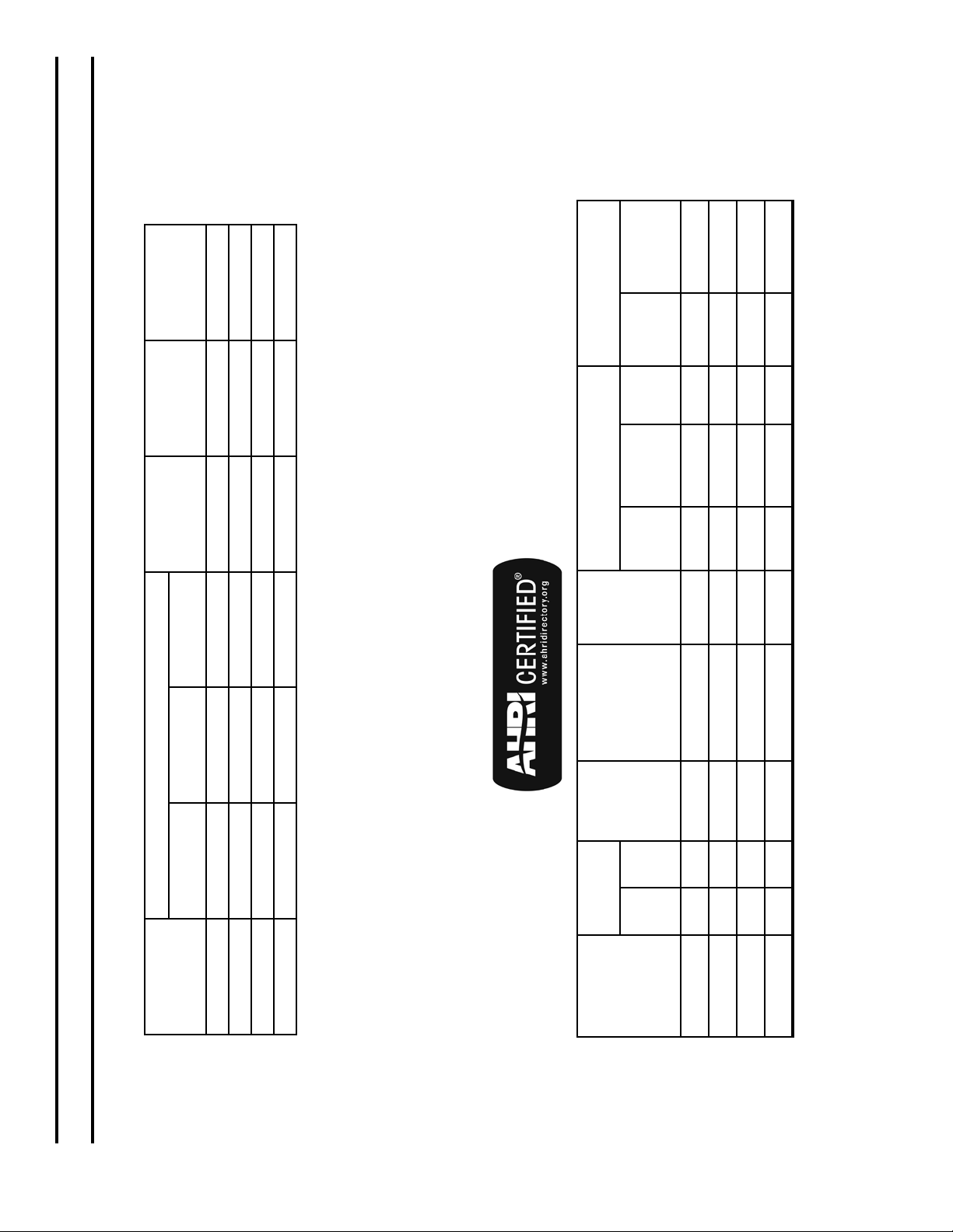
Dimensions See Figure 1
“A” “B” “C”
No.
CI-HGS-74B 17” 24” 5” 7.70 13.29 430
Boiler Model
TABLE 1A: DIMENSIONAL DATA (SEE FIGURE 1)
CI-HGS-101B 17” 24” 5” 7.70 13.29 430
CI-HGS-129B 23” 24” 6” 11.08 20.29 545
CI-HGS-167B 29” 30” 6” 14.46 27.29 658
NOTE: 1. Maximum Working Pressure: Water: 30 PSI Shipped From Factory (Standard),
40 PSI Optional, 50 PSI Optional
DOE
Input
TABLE 1B: RATING DATA
(MBH)
Heating
Capacity
GPH MBH
No.
Boiler Model
CI-HGS-74B 0.60 84 74 64 87 6 8 x 8 15 N/A N/A
CI-HGS-101B 0.80 115 101 87 87 6 8 x 8 15 N/A N/A
CI-HGS-129B 1.05 147 129 112 87 6 8 x 8 15 FDVS-56 5
CI-HGS-167B 1.35 189 167 145 87 7 8 x 8 15 FDVS-56 5
SECTION I: GENERAL INFORMATION (continued)
6
SECTION II: PRE-INSTALLATION
A. INSPECT SHIPMENT carefully for any signs of
damage.
1. All equipment is carefully manufactured, inspected
and packed. Our responsibility ceases upon delivery
of crated boiler to the carrier in good condition.
2. Any claims for damage or shortage in shipment
must be led immediately against the carrier by the
consignee. No claims for variances from, or shortage
in orders, will be allowed by the manufacturer
unless presented within sixty (60) days after receipt
of goods.
B. LOCATE BOILER in front of nal position before
removing crate. See Figure 1.
1. LOCATE so that vent pipe connection to chimney
will be short and direct.
2. BOILER IS SUITABLE FOR INSTALLATION
ON COMBUSTIBLE FLOOR. Boiler cannot be
installed on carpeting.
3. FOR BASEMENT INSTALLATION, provide
a solid elevated base, such as concrete, if oor is
not level, or if water may be encountered on oor
around boiler.
4. PROVIDE RECOMMENDED SERVICE
CLEARANCE, if applicable, as follows:
a. Clearance from Jacket Front Panel -
• 24” for servicing burner
• 24” for ueway cleaning (CI-HGS-74B thru
CI-HGS-129B)
• 30” for ueway cleaning (CI-HGS-167B)
b. Clearance from Jacket Left Side Panel -
• 19” for burner swing door, if opened fully
with burner mounted, otherwise 1” with
burner removed
• 12” access clearance to service rear of
boiler if right side clearance is less
than 12”
• 3” minimum if right side clearance is 12” or
larger to access and service rear of boiler.
c. Clearance from Jacket Right Side Panel -
• 3” minimum if left side clearance is 12” or
larger to access and service rear of boiler.
d. Clearance from Jacket Rear Panel -
• 12” minimum for rear smokebox cleaning
(Note: This dimension will also be
controlled by horizontal to vertical to
horizontal smokepipe arrangement Chimney Vent (see Figures 2A and 13).
• 24” for rear smoke box cleaning and
disconnecting vent pipe from boiler adaptor
for servicing (if required) - Direct Vent (see
Figures 2B and 25).
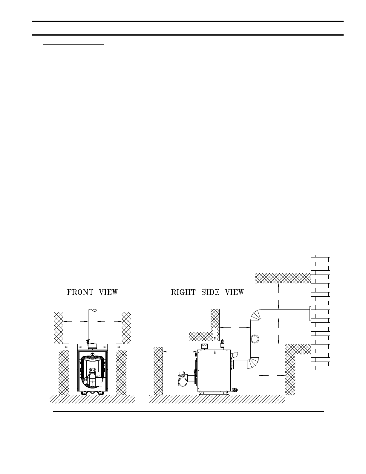
5. For minimum clearances to combustible materials.
See Figures 2A and 2B.
18"
18"
6" 6"
18"
18"
6"
24"
18"
18"
Figure 2A: Chimney Vent - Minimum Installation Clearances To Combustible Materials (Inches)
NOTES: 1. Listed clearances comply with American National Standard ANSI/NFPA 31, Standard for the Installation of Oil Burning Equipment.
2. CI-HGS-B boilers can be installed in rooms with clearances from combustible material as listed above. Listed clearances cannot be reduced for
alcove or closet installations.
3. For reduced clearances to combustible material, protection must be provided as described in the above ANSI/NFPA 31 standard.
7

SECTION II: PRE-INSTALLATION (continued)
NOTICE
Clearance to venting is for single wall vent
pipe. If Type L vent is used, clearance may be
reduced to the minimum required by the vent pipe
manufacturer.
C. PROVIDE COMBUSTION AND VENTILATION
AIR. Local and National Codes may apply and should
be referenced.
WARNING
Adequate combustion and ventilation air must
be provided to assure proper combustion and
to maintain safe ambient air temperatures.
Do not install boiler where gasoline or other
ammable vapors or liquids, or sources of
hydrocarbons (i.e. bleaches, fabric softeners,
etc.) are used or stored.
1. Determine volume of space (boiler room). Rooms
communicating directly with the space in which
the appliances are installed, through openings not
furnished with doors, are considered a part of the
space.
3
Volume(ft
2. Determine total input of all appliances in the space.
Add inputs of all appliances in the space and round
the result to the nearest 1000 BTU per hour.
) = Length(ft) x Width(ft) x Height(ft)
3. Determine type of space. Divide Volume by total
input of all appliances in space. If the result is
3
greater than or equal to 50 ft
/1000 BTU per hour,
then it is considered an unconned space. If the
result is less than 50 ft3/1000 BTU per hour then the
space is considered a conned space.
4. For boiler located in an unconned space of a
conventionally constructed building, the fresh
air inltration through cracks around windows
and doors normally provides adequate air for
combustion and ventilation.
5. For boiler located in a conned space or an
unconned space in a building of unusually tight
construction, provide outdoor air. Outdoor air
may be provided with the use of two permanent
openings which communicate directly or by duct
with the outdoors or spaces (crawl or attic) freely
communicating with the outdoors. Locate one
opening within 12 inches of top of space. Locate
remaining opening within 12 inches of bottom of
space. Minimum dimension of air opening is 3
inches. Size each opening per following:
a. Direct communication with outdoors.
Minimum free area of 1 square inch per 4,000
BTU per hour input of all equipment in space.
b. Vertical ducts. Minimum free area of 1 square
inch per 4,000 BTU per hour input of all
equipment in space. Duct cross-sectional area
shall be same as opening free area.
3"3"
AIR INTAKE
AIR
INTAKE
PIPING
6"6"
PIPING
(REMOVED
FOR CLARITY)
Figure 2B: Direct Vent - Minimum Installation Clearances To Combustible Materials (Inches)
NOTES: 1. Listed clearances comply with American National Standard
ANSI/NFPA 31, Standard for the Installation of Oil Burning
Equipment.
2. CI-HGS-B boilers can be installed in rooms with clearances from
combustible material as listed above. Listed clearances cannot
be reduced for alcove or closet installations.
8
FDVS
AIR
INTAKE
PIPING
DIRECT
VENT
VENT
PIPING
6"
24"
3. For reduced clearances to combustible material, protection
must be provided as described in the above ANSI/NFPA 31
standard.
3"
3"
3"
6"

SECTION II: PRE-INSTALLATION (continued)
c. Horizontal ducts. Minimum free area of 1
square inch per 2,000 BTU per hour input of all
equipment in space. Duct cross-sectional area
shall be same as opening free area.
Alternate method for boiler located within
conned space. Use indoor air if two permanent
openings communicate directly with additional
space(s) of sufcient volume such that combined
volume of all spaces meet criteria for unconned
space. Size each opening for minimum free area
of 1 square inch per 1,000 BTU per hour input
of all equipment in spaces, but not less than 100
square inches.
6. Louvers and Grilles of Ventilation Ducts
a. All outside openings should be screened and
louvered. Screens used should not be smaller
than 1/4 inch mesh. Louvers will prevent the
entrance of rain and snow.
b. Free area requirements need to consider the
blocking effect of louvers, grilles, or screens
protecting the openings. If the free area of the
louver or grille is not known, assume wood
louvers have 20-25 percent free area and metal
louvers and grilles have 60-75 percent free area.
c. Louvers and grilles must be xed in the open
position, or interlocked with the equipment to
open automatically during equipment operation.
D. DIRECT VENT CONFIGURATIONS requires:
1. Beckett NX Burner
2. Direct Vent conversion Kit
3. Double Wall Flex Oil Vent Pipe (FOVP)
TABLE 2: DIRECT VENT CONFIGURATION COMPONENTS
Boiler
Model No.
CI-HGS-129B 106795-01
CI-HGS-167B 106796-01
Beckett NX
Oil Burner
Part No.
Direct Vent
Conversion Kit
Part No.
106797-01
FOVP Carton
Part No.
100211-02 - 5 ft.
100212-02 - 10 ft.
100213-02 - 15 ft.
100214-02 - 20 ft.
9
SECTION III: PACKAGED BOILER ASSEMBLY - TRIM & CONTROLS
A. REMOVE CRATE.
1. Remove all fasteners at crate skid.
2. Lift outside container and remove all other
inside protective spacers and bracing. Remove
miscellaneous parts carton.
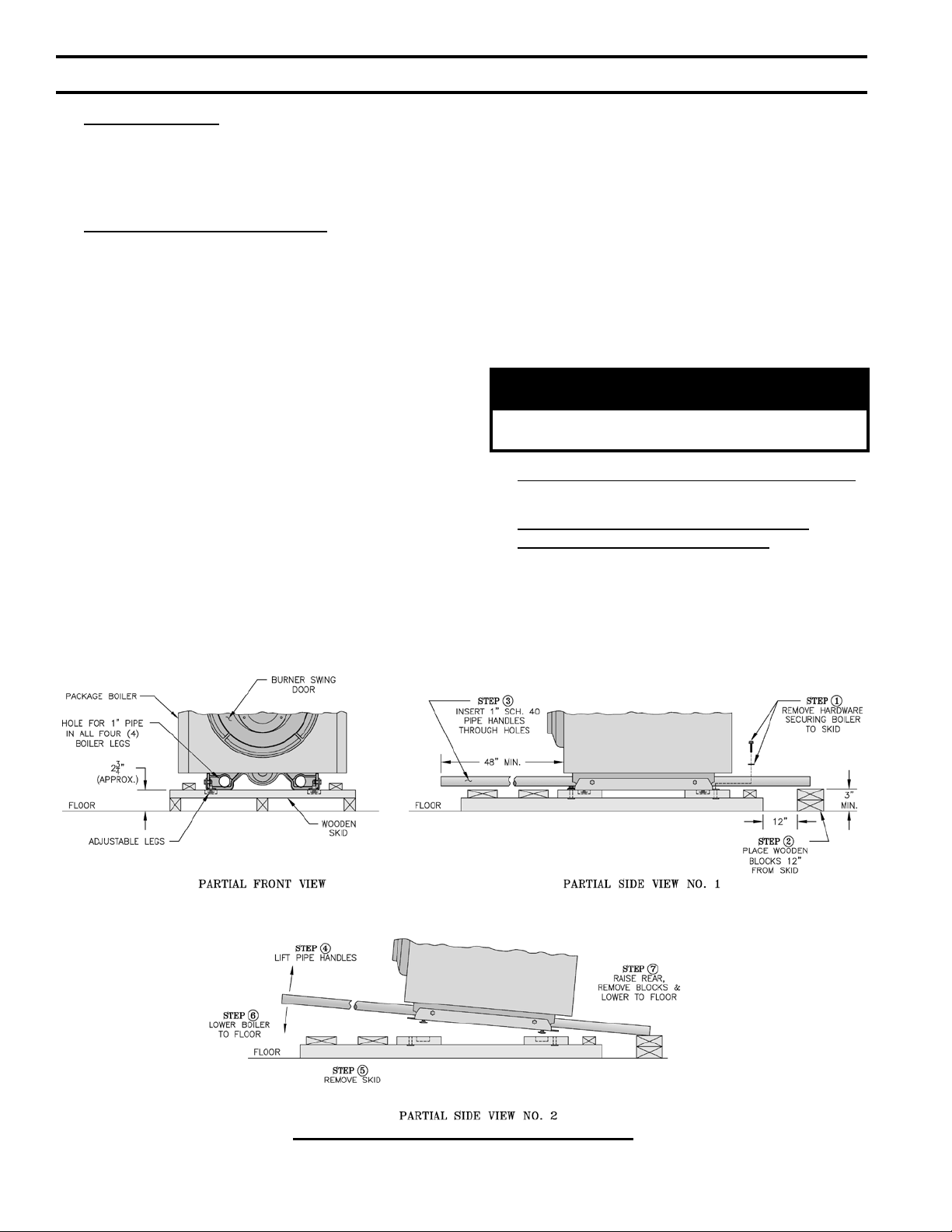
B. REMOVE BOILER FROM SKID.
1. To reduce the risk of damage to boiler jacket, use
the following procedure to remove from skid, see
Figure 3:
Step 1. Boiler is secured to base with (4) 5/16” cap
screws, (2) in front and (2) in rear of shipping
skid, see Figure 3. Remove all securing
hardware.
Step 2. Place wooden block(s) 12” from rear of
skid as shown (one piece 4” x 4” x 16” lg. or two
pieces of 2” x 4” x 16” lg.)
Step 3. Insert 1” Sch. 40 pipe handles through leg
hole in front and rear legs. Center end of pipe on
wooden blocks as shown in Figure 3.
NOTE: Pipe handles should extend a minimum
of 48” beyond jacket front panel for best
leverage.
Step 4. Using the pipe handles, lift boiler until
adjustable legs are elevated above the deck
boards.
Step 5. Remove skid from underneath the boiler.
Step 6. Lower pipe handles until front adjustable
legs touch oor. If necessary, place wooden
blocks under front legs before lowering to
provide hand clearance.
Step 7. To lower rear of boiler, tilt unit slightly
forward by pushing on smokebox collar or lift
pipes protruding through rear legs until wooden
blocks can be removed (see Figure 3). Slowly
allow the weight of the boiler to tilt backward
until rear legs rest on oor.
Step 8. If wood block was placed under front legs,
lift pipe handles, remove wooden block and
lower front legs to oor. Remove pipe handles.
CAUTION
Do not drop boiler. Do not bump boiler jacket
against oor.
C. MOVE BOILER TO PERMANENT POSITION
by sliding or walking.
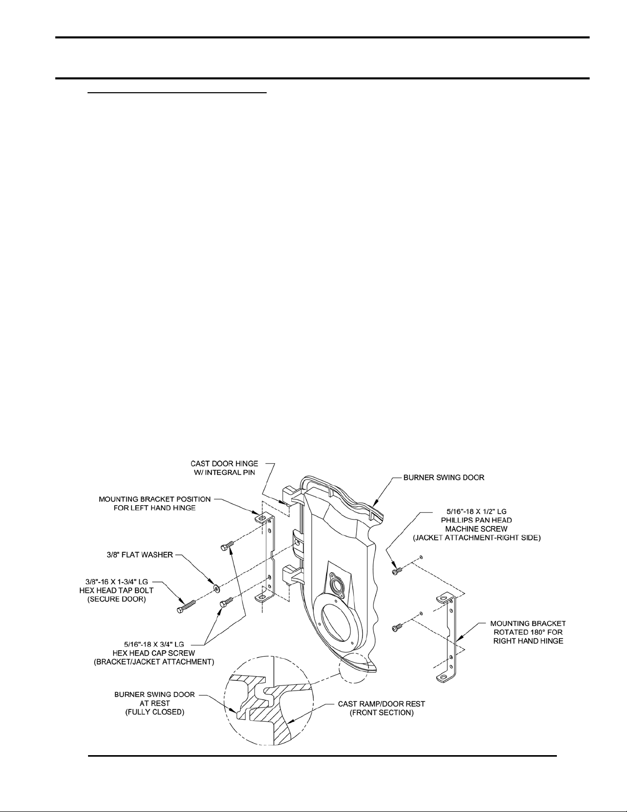
D. PROCEDURE TO OPEN, CLOSE AND
SECURE BURNER SWING DOOR
Throughout this manual you will be instructed to open
and close the burner swing door for various reasons.
There is a proper and improper method to closing and
securing the burner swing door opened for inspection,
cleaning or eld service.
10
Figure 3: Packaged Boiler Removal from Skid
SECTION III: PACKAGED BOILER ASSEMBLY - TRIM & CONTROLS
(continued)
1. TO OPEN BURNER SWING DOOR
(see Figures 4A and 4B).
Step 1. Loosen but do not remove left side latching
hardware (3/8” x 1-3/4” lg. tap bolt).
Step 2. Loosen and remove right side latching
hardware (3/8” x 1-3/4” lg. tap bolt and washer).
Step 3. Remove left side latching hardware (3/8” x
1-3/4” lg. tap bolt and washer).
Step 4. Disconnect burner power cord from
receptacle located in lower right corner of jacket
front panel.
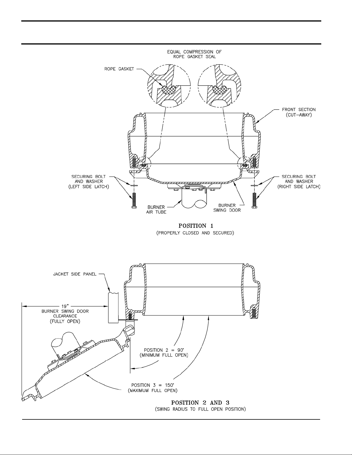
Step 5. Door can be swung to the fully open
position, approximately 90° to 120°, with the
burner mounted providing that there is 19” of
clearance to the adjacent wall, see Figure 1.
NOTE: If reduced clearance prevents the door
from opening fully, one of the following can
provide full access:
a. Burner can be removed to allow full rotation
of door.
b. Door with burner mounted can be lifted
off mounting bracket and set aside during
servicing.
c. The door mounting hardware is reversible
from left side hinge (as shipped) to right side
hinge.
To reverse hinge arrangement (see Figure
4A):
• Lift door off mounting bracket and set
aside.
• Remove mounting bracket and hardware
from left side.
• Remove upper jacket front panel retaining
screw (5/16” x 1/2” lg. Phillip Pan head
machine screw) from right side of door
and re-install in vacated upper mounting
bracket tapping. Do not tighten.
• Move lower jacket panel retaining screw
from right side to left tapping. Do not
tighten.
• Rotate door mounting bracket 180°.
Insert 5/16” cap screw through top hole in
bracket and install in upper vacated jacket
hole on right side of door.
• Install second 5/16” cap through bracket
hole into lower vacated tapping on right
side.
• Tighten both sets of hardware to secure
jacket and mounting bracket.
• Lift door and place integral cast hinge
pins on door into slotted mounting bracket
holes.
2. Perform routine inspection, service or cleaning as
necessary.
3. To close Burner Swing Door (see Figures 4A and
4B):
Figure 4A: Partial Front View - Burner Swing Door Mounted to Boiler - Fully Closed and Secured
11
SECTION III: PACKAGED BOILER ASSEMBLY - TRIM & CONTROLS
(continued)
Figure 4B: Top View - Burner Swing Door Mounted to Cast Iron Block Assembly (Jacket Removed for Clarity)
12
SECTION III: PACKAGED BOILER ASSEMBLY - TRIM & CONTROLS
(continued)
Step 1. From the fully open position, rotate Burner
Swing Door to the closed position.
Step 2. If necessary, place your right hand under
the burner air tube to lift upward. Lift the
door up unto the built-in cast ramp/door rest
(protruding from the bottom of the front section
casting - see Figure 4A).
Step 3. Use one hand to help hold door in position
by lifting up on rear burner housing or applying
pressure directly to the door while re-installing
the securing hardware with your opposite hand.
Always install right side latching hardware
(3/8”-16 x 1-3/4” lg. tap bolt and at washer)
rst, then install left side hinge hardware
(3/8”-16 x 1-3/4” lg. tap bolt and at washer)
second. Apply additional pressure while hand
tightening the hardware as far as possible, then
release the pressure.
NOTICE
When securing burner swing door make sure
door is drawn-in equally on both sides.
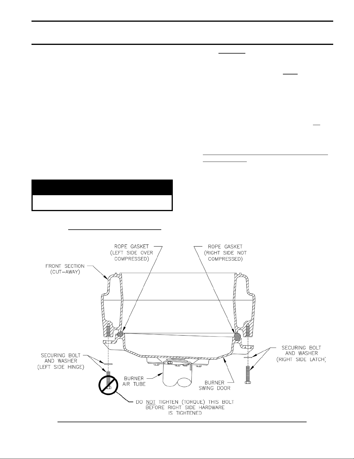
Step 4. Use a hand wrench to tighten door hardware
and always start with the right side cap
screw rst. Use an alternating tightening
method from right side tap bolt to left side tap
bolt to tighten door equally until sealed without
applying excessive torque. Never tighten left
side ange bolt rst or tighten either piece of
hardware 100% without using the alternating
tightening method described above.
Failure to follow the prescribed procedure could
cause thread damage to casting or a leak in the
door seal. If left side tap bolt is tightened before
right side tap bolt, right side of door can not be
drawn-in to provide an air tight seal, as shown in
Figure 4C. Applying excessive torque will only
cause thread damage.
E. INSPECT SWING DOOR INSULATION AND
ROPE GASKET.
1. Open burner swing door using procedure previously
outlined in Paragraph D of this section.
2. Inspect berglass rope located on the swing door.
The rope must be evenly distributed around the
perimeter of the door groove and cannot bunch or
overhang. There must not be a gap where the two
ends of the rope meet. Repair or replace if the rope
is damaged or if there is a gap between the ends.
3. Inspect burner swing door insulation for damage and
proper type.
Figure 4C: Top View - Burner Swing Door Fully Closed but Not Properly Secured or Sealed
13
SECTION III: PACKAGED BOILER ASSEMBLY - TRIM & CONTROLS
(continued)
By design, cast bars on front section between the
combustion chamber and between the left and
right side 2nd and 3rd pass ueway should make an
impression in door insulation to seal the chambers.
If insulation is damaged or not of proper type
regarding pockets, it must be replaced.
4. Do not close and secure door at this time, proceed to
Field Assembly Details, Paragraph F.
F. FIELD ASSEMBLY OF BOILER TRIM AND
CONTROLS
Open miscellaneous parts carton and remove contents.
Identify the components using the illustrations (see
Figure 5) throughout the assembly sequence outlined
below as it applies to your installation.
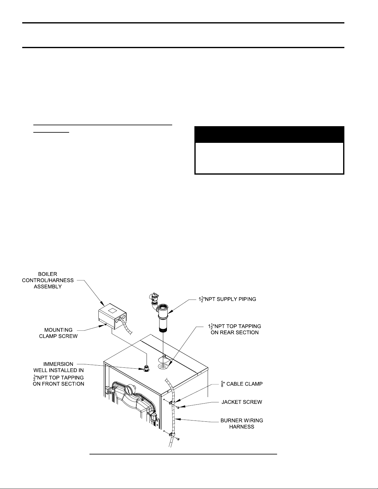
1. Install supply piping and relief valve, refer to
Figures 1 and 5.
Step a. Locate the supply piping supplied with
boiler. Apply thread sealant to all joints
prior to assembly. Thread 1½” NPT x 6”
long supply nipple into 1½” NPT tapping
on the topside of the rear section. Thread
1½” x 1½” x ¾” NPT tee onto 6” nipple.
Tighten all joints until watertight and ¾”
NPT connection on tee is positioned to allow
clearance for relief valve discharge.
Step b. Locate the relief valve piping supplied
with boiler. Apply thread sealant to all joints
prior to assembly. Thread the ¾” NPT street
elbow onto tee listed above. Install relief
valve into street elbow. Tighten all joints
until watertight and relief valve is positioned
to allow clearance for discharge. Installation
of the relief valve must be consistent with
ANSI/ASME Boiler and Pressure Vessel
Code, Section IV.
WARNING
Safety valve discharge piping must be piped near
oor to eliminate potential of severe burns. Do
not pipe in any area where freezing could occur.
Do not install any shut-off valves, plugs or caps.
2. Install Boiler Control
a. Locate the Boiler Control/Harness Assembly
in the Miscellaneous Parts Carton. Loosen
mounting clamp screw on front of Control.
Mount Control on factory installed immersion
well located in top tapping near front of boiler
with burner harness on the right hand side; see
Figure 5.
b. Locate (2) 5/8” cable clamps in parts carton.
Secure burner wiring harness to front of jacket
right side panel with cable clamps and existing
jacket screws at top and mid-point as shown in
Figure 5.
14
Figure 5: Supply Piping and Aquastat Control Assembly Details
SECTION III: PACKAGED BOILER ASSEMBLY - TRIM & CONTROLS
(continued)
c. Locate the Limit sensor inside Boiler Control.
Carefully connect sensor into the Boiler Control
circuit board by pressing connector on sensor
unit into mating connector on circuit board
(refer to Figure 40). Insert sensor through hole
in circuit board and into immersion well until it
rests against the bottom of the well as shown in
Figure 6.
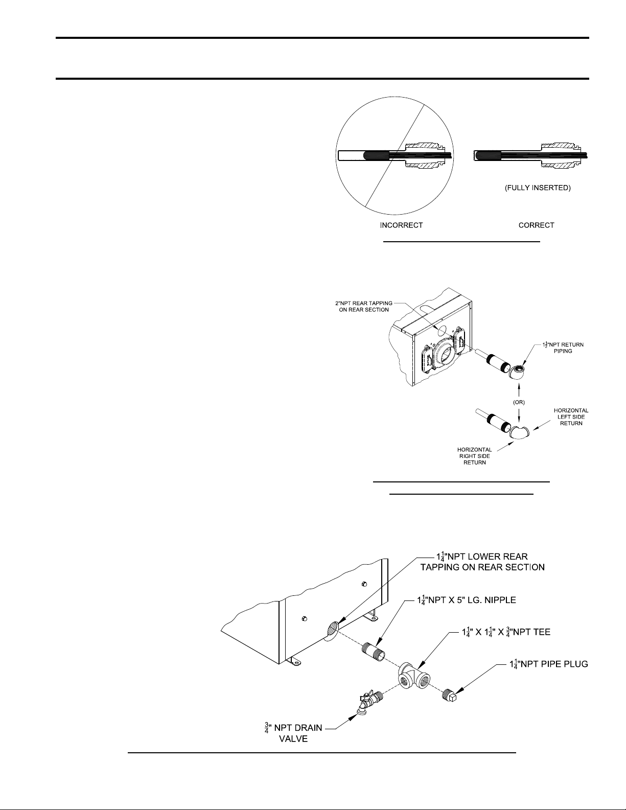
3. Install return injector piping and relief valve, refer to
Figure 7.
Step a. Locate the return pipe ttings and
injector. Apply sealant to the 2” NPT
injector threads. Insert injector into 2” NPT
upper rear tapping on rear section. Thread
2” NPT x 1-1/2” Reducing Elbow onto 2”
NPT injector.
Note: Based on system return piping and
access to service boiler, see Figures 1, 11A
and 11B, predetermine if injector piping
orientation is to be positioned for vertical,
horizontal left or horizontal right side return
piping as shown in Figure 7.
4. Install drain valve, see Figure 8.
Step a. Apply pipe sealant to both ends of
1-1/4” NPT x 5” lg. nipple. Thread nipple
into 1-1/4” NPT lower rear tapping on rear
section.
Step b. Thread 1-1/4” x 1-1/4” x 3/4” NPT tee
on opposite end of 5” lg. nipple installed in
Step a.
NOTE: Based on access for servicing
and location of sewer or oor drain, when
tightening these ttings, determine if drain
valve is to be located on the left or right
side.
Tighten nipple and tee into 1-1/4” NPT
lower rear tapping on rear section until joints
are water tight for desired position.
Figure 6: Limit Sensor Insertion
Figure 7: Return Injector Piping and
Relief Valve Assembly Details
Figure 8: Piping Arrangement for Drain Valve and Indirect Water Heating Return
15
SECTION III: PACKAGED BOILER ASSEMBLY - TRIM & CONTROLS
(continued)
Step c. Apply sealant to 3/4” NPT thread on
drain valve. Thread into 3/4” NPT tapping
on side outlet of tee. Use hex nut portion to
tighten valve until water tight.
5. Connect Field Wiring.
Step a. Connect the eld wiring from the
circulator to the aquastat control. Make the
wiring connections as shown on Figures 27
or 28.
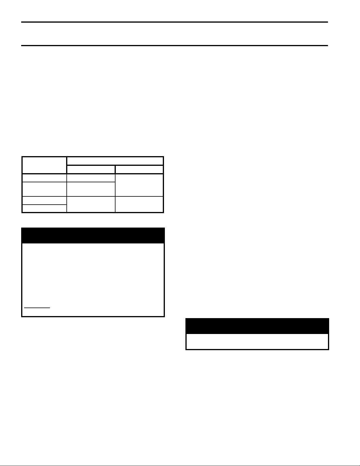
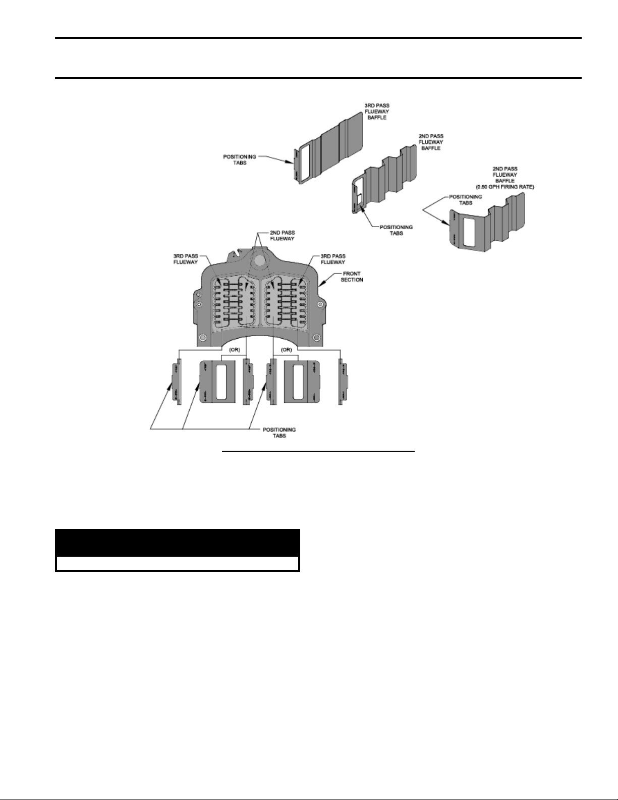
6. Installing stainless steel ueway bafes. Bafe
requirements differ from model to model, see
Table 3.
TABLE 3: BAFFLE USAGE
Boiler Model
CI-HGS-74B None
CI-HGS-101B
CI-HGS-129B
CI-HGS-167B
2
P/N 102066-01
P/N 100042-01
Bafe Usage
nd
Pass 3rd Pass
[2]
[2]
[2]
P/N 100081-01
None
NOTE: Read caution statement before proceeding.
CAUTION
These bafes will generate higher efciencies
and lower stack temperatures. Under certain
conditions, a lower gross stack temperature
entering the chimney has the potential to be
cooled below the dew point and create condensate
on interior surfaces. Flue gas condensate is
corrosive, which requires special consideration
and must be addressed immediately.
DO NOT install bafes until you have read
Sections VI and VII, completely (venting details).
• Model CI-HGS-101B - To install ueway
rd
bafe in 3
pass on left side of boiler, hold
bafe with word “Left” readable at the top.
Slide bafe in ueway until position tab
touches ns on left side of 3rd pass ueway.
To install ueway bafe in 3rd pass ueway
on right side of boiler, hold bafe with
word “Right” readable at the top. Slide
bafe in ueway until position tab touches
ns on right side of 3rd pass ueway. To
install ueway bafe in 2nd pass on left
side of boiler, hold bafe with word “Left”
readable at the top. Slide bafe in ueway
until position tab touches ns on left side
of 3rd pass ueway. To install ueway
bafe in 2nd pass ueway on right side
of boiler, hold bafe with word “Right”
readable at the top. Slide bafe in ueway
until position tab touches ns on right side
of 3rd pass ueway.
• Models CI-HGS-129B and CI-HGS-
167B To install ueway bafe in 2nd pass
ueway on left side of boiler, hold bafe
with word “Left” readable at the top. Slide
bafe in ueway until position tab touches
ns on right side of 2nd pass ueway. To
install ueway bafe in 2nd pass ueway on
right side of boiler, hold bafe with word
“Right” readable at the top. Slide bafe in
ueway until position tab touches ns on
left side of 2nd pass ueway.
NOTE: 2nd and 3rd pass ueway bafe are not
interchangeable.
7. Close the burner swing door and securely seal the door
to the boiler front section by reinstalling the hardware
and securing the door using procedure previously
outlined in Paragraph D of this section.
16
Step a. Install stainless steel bafes provided in
miscellaneous parts carton as follows, refer
to Table 3 and Figure 9:
• Model CI-HGS-74B - To install ueway
bafe in 3
rd
pass on left side of boiler, hold
bafe with word “Left” readable at the
top. Slide bafe in ueway until position
tab touches ns on left side of 3rd pass
ueway. To install ueway bafe in 3rd
pass ueway on right side of boiler, hold
bafe with word “Right” readable at the
top. Slide bafe in ueway until position
tab touches ns on right side of 3rd pass
ueway.
NOTICE
When securing burner swing door make sure
door is drawn-in equally on both sides.
SECTION III: PACKAGED BOILER ASSEMBLY - TRIM & CONTROLS
(continued)
Figure 9: Bafe Orientation in Flueways
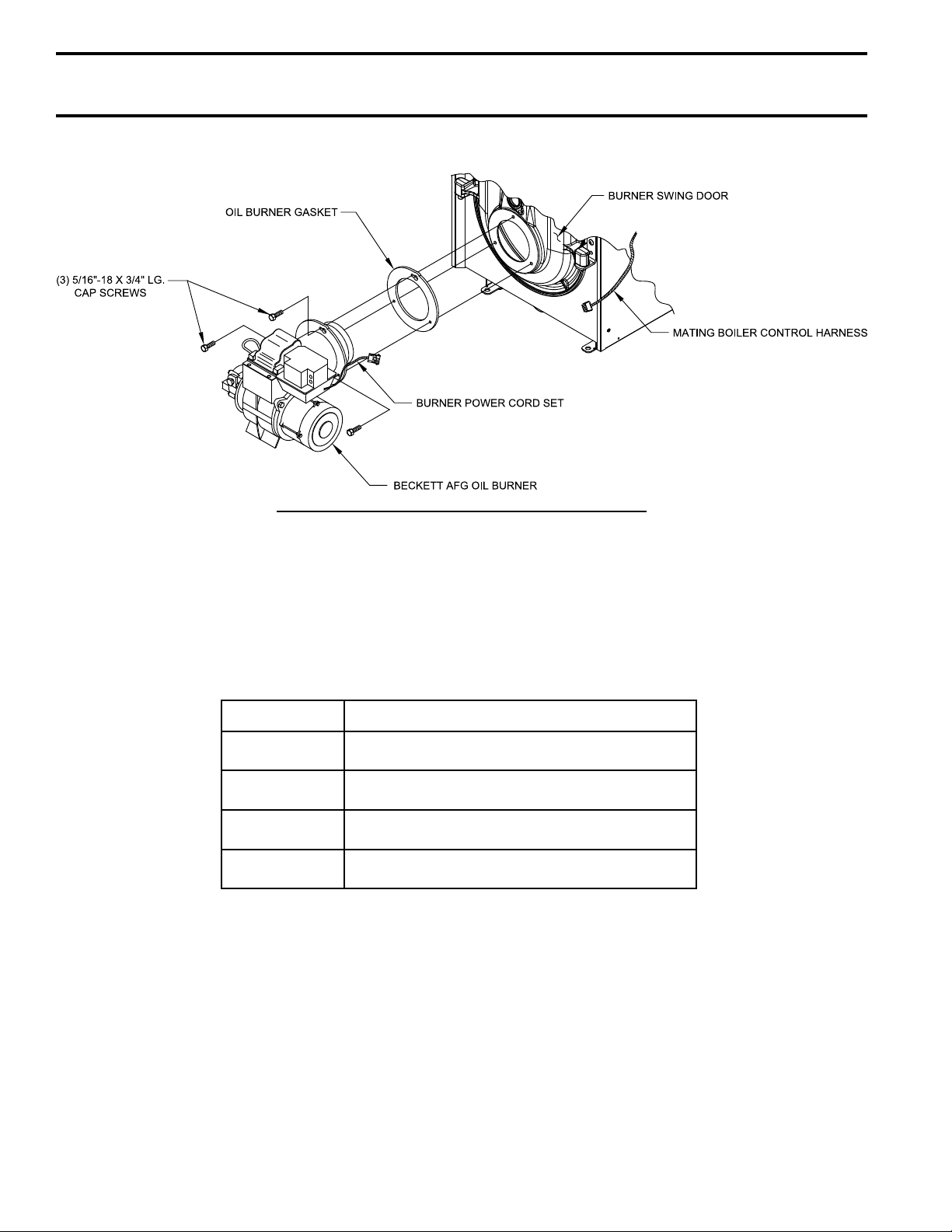
8. Install oil burner. (See Figure 10 and Table 4)
Step a. Open burner carton and remove contents.
Step b. Place oil burner gasket on burner and align holes.
CAUTION
Do not install burner without gasket.
Step c. Remove three (3) 5/16-18 x 3/4 lg. cap screw
from burner swing door used for mounting burner.
Step d. Thread (1) 5/16-18 x 3/4 lg. cap screw,
approximately three (3) full turns, into tapping
located at 12:00 o’clock on burner swing door.
Step e. Insert oil burner into the opening of burner
swing door. Align and engage keyhole slot in burner
ange over head of protruding cap screw installed
in previous Step. Rotate burner to the right to lock
ange behind head of cap screw.
Step f. Align holes and install two (2) remaining cap
screws. Level burner and fully tighten all three
(3) screws.
Step g. Plug burner power cord into Boiler Control
harness.
Step h. Check oil nozzle in burner for size, angle and
spray type; inspect electrode settings and head/air
plate setting. Refer to Tables 17, 18 and 19 and
Section X. Refer to Burner Manufacturer’s Manual
for detail instructions.
17
SECTION III: PACKAGED BOILER ASSEMBLY - TRIM & CONTROLS
(continued)
Figure 10: Oil Burner Installation (Beckett shown)
TABLE 4: BURNER-N-BOX BURNERS
Boiler Model Burner Part Numbers
CI-HGS-74B 106771-01 (Beckett), 106775-01 (Carlin)
CI-HGS-101B 106772-01 (Beckett), 106776-01 (Carlin)
CI-HGS-129B 106773-01 (Beckett), 106777-01 (Carlin)
CI-HGS-167B 106774-01 (Beckett), 106778-01 (Carlin)
18
SECTION IV: WATER BOILER PIPING
NOTICE
Failure to pipe boiler as specied in this manual may result in excessive system noise.
A. EVALUATE THE EXISTING WATER
SYSTEM.
Design a piping system and install boiler which will
prevent oxygen contamination of boiler water and
frequent water additions.
1. There are many possible causes of oxygen
contamination such as:
a. Addition of excessive make-up water as a result
of system leaks.
b. Absorption through open tanks and ttings.
c. Oxygen permeable materials in the distribution
system.
2. In order to insure long product life, oxygen sources
must be eliminated. This can be accomplished by
taking the following measures:
a. Repairing system leaks to eliminate the need for
addition of make-up water.
b. Eliminating open tanks from the system.
c. Eliminating and/or repairing ttings which allow
oxygen absorption.
d. Use of non-permeable materials in the
distribution system.
e. Isolating the boiler from the system water by
installing a heat exchanger.
WARNING
System supply and return piping must be
connected to correct boiler manifolds.
New Yorker Boiler Co. recommends sizing
the system circulator to supply sufficient
flow (GPM) to allow a 20°F temperature
differential in the system. When sizing the
system circulator, the most restrictive single
zone should be used to determine maximum
pressure drop.
CAUTION
Maintain minimum ½ inch clearance from hot
water piping to combustible materials.
3. In order to insure long product life, operate boiler at
appropriate ow rate to minimize areas of overheating
a. Design system to ensure that the ow is above the
limit called for in Table 5.
b. Maintain a constant boiler pressure of 12 PSI.
TABLE 5: MINIMUM FLOW RATE
Boiler Model No. Flow Rate (Gal / Min)
CI-HGS-74B 4.5
CI-HGS-101B 6.0
CI-HGS-129B 8.0
CI-HGS-167B 10.0
WARNING
Do not operate boiler below minimum volumetric
ow rates.
B. CONNECT SYSTEM SUPPLY AND RETURN
PIPING TO BOILER. See Figures 11A and 11B.
Also, consult Residential Hydronic Heating Installation
and Design I=B=R Guide.
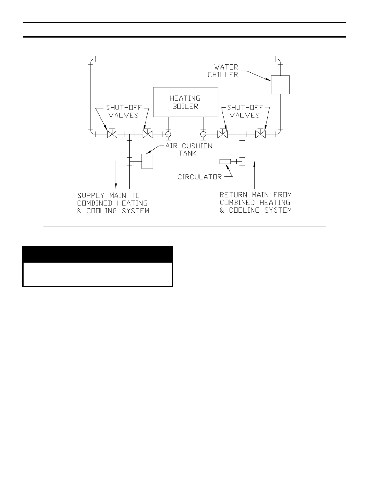
1. If this boiler is used in connection with refrigeration
systems, the boiler must be installed so that the chilled
medium is piped in parallel with the heating boiler using
appropriate valves to prevent the chilled medium from
entering the boiler. See Figure 11C. Also, consult
Residential Hydronic Heating Installation and Design
I=B=R Guide.
2. If this boiler is connected to heating coils located
in air handling units where they may be exposed to
refrigerated air, the boiler piping must be equipped
with ow control valves to prevent gravity circulation
of boiler water during the operation of the cooling
system.
3. If an indirect water heater is used, priority zoning can
be used. Do not use priority zoning for Hydro-Air
Systems. Refer to the Indirect Water Heater Installation,
Operating, and Service Instructions for additional
information.
4. The CI-HGS-B is designed to withstand thermal shock
from return water temperatures as low as 100°F, but
prolonged return temperatures of below 135°F can
cause excessive ue gas condensation and damage
the boiler and/or venting system.
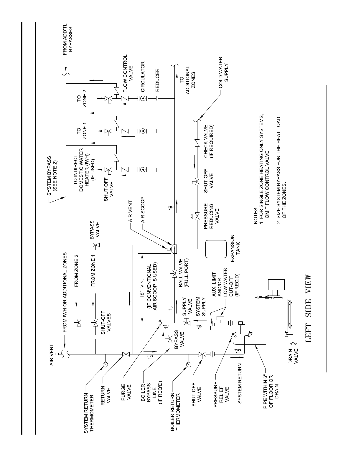
Use a boiler bypass if the boiler is to be operated
in a system which has a large volume or excessive
.
radiation where low boiler water temperatures may be
encountered (i.e. converted gravity circulation system,
etc.) The bypass should be the same size as the supply
and return lines with valves located in the bypass and
return line as illustrated in Figures 11A and 11B in
order to regulate water ow for maintenance of higher
boiler water temperature.
19
20
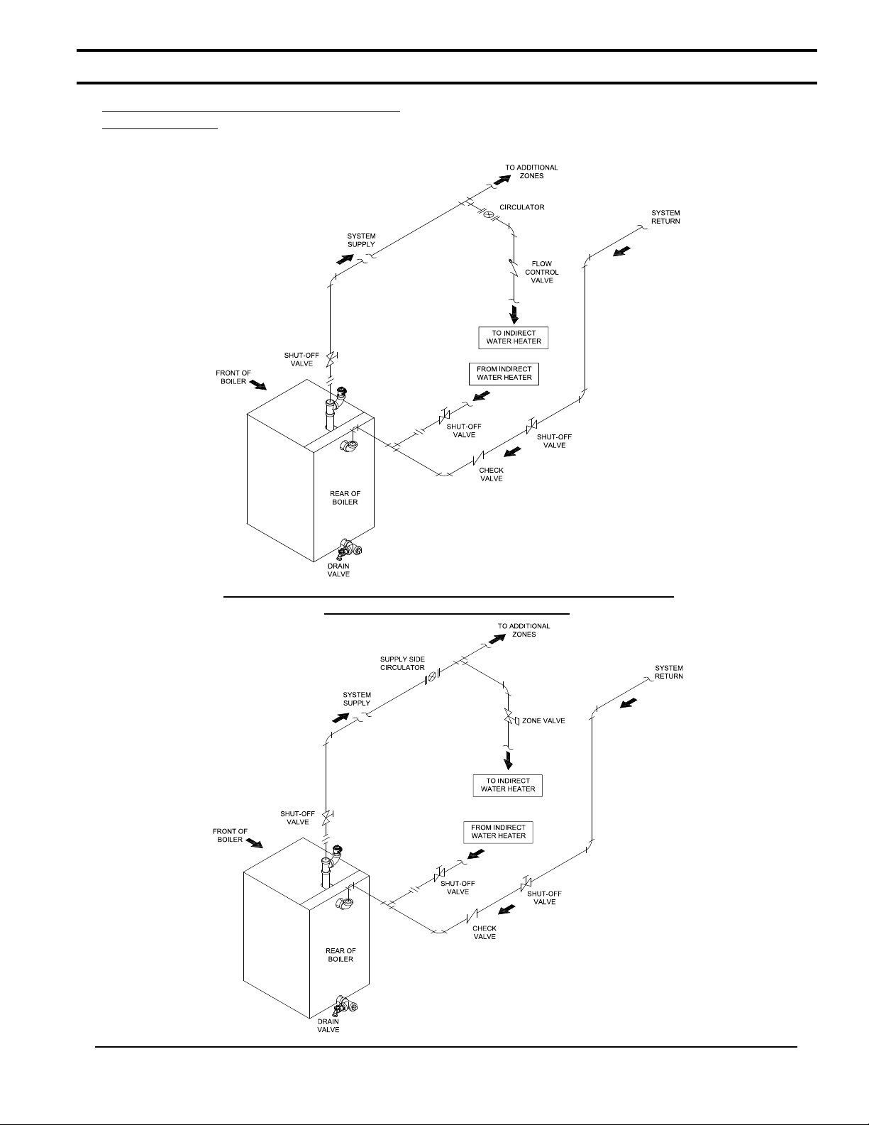
Figure11A: Recommended Water Piping for Circulator Zoned Heating Systems - Supply Side Circulator
SECTION IV: WATER BOILER PIPING (continued)
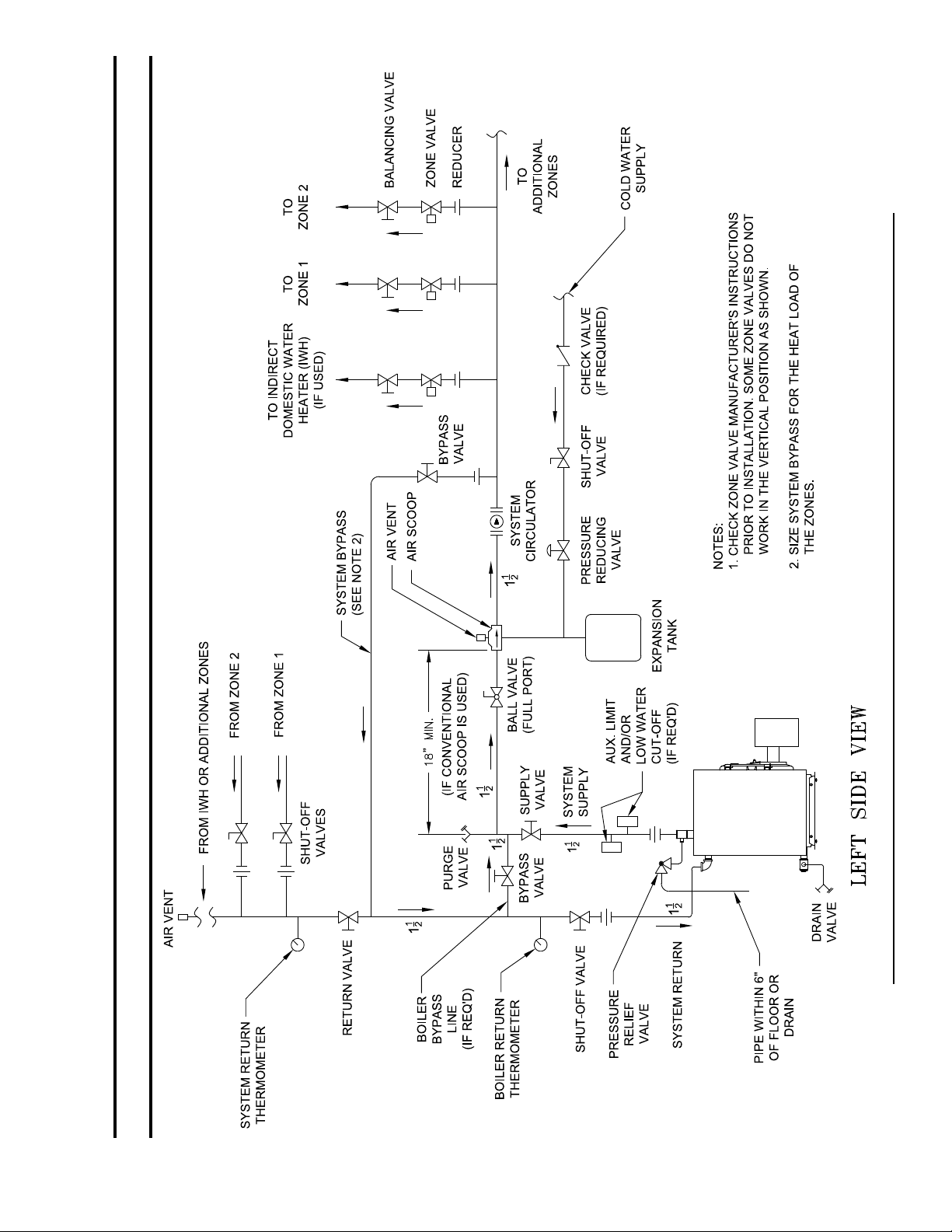
Figure 11B: Recommended Water Piping for Zone Valve Zoned Heating Systems - Supply Side Circulator
SECTION IV: WATER BOILER PIPING (continued)
21
SECTION IV: WATER BOILER PIPING (continued)
Figure 11C: Recommended Piping for Combination Heating and Cooling (Refrigeration) System
5. If it is required to perform a long term pressure
WARNING
The use of a low water cut-off device, while not
required unless radiation level is below the boiler,
is highly recommended.
If a low water cut-off is required, it must be
mounted in the system piping above the boiler. The
minimum safe water level of a hot water boiler is
just above the highest water containing cavity of
the boiler; that is, a hot water boiler must be full of
water to operate safely.
test of the hydronic system, the boiler should rst
be isolated from the system to avoid a pressure loss
due to the escape of air trapped in the boiler.
To perform a long term pressure test including the
boiler, ALL trapped air must rst be removed from
the boiler.
A loss of pressure during such a test, with no visible
water leakage, is an indication that the boiler
contained trapped air.
22
SECTION V: INDIRECT WATER HEATER PIPING
A. CONNECT INDIRECT DOMESTIC WATER
HEATER PIPING as shown in Figure 12A and 12B.
Also refer to Figures 11A and 11B.
1. Refer to instructions furnished with Indirect Water
Heater for additional information.
Figure 12A: Indirect Water Heater Piping w/Supply Side Circulator
on Circulator Zoned Heating System
Figure 12B: Indirect Water Heater Piping w/Supply Side Circulator on Zone Valve Zoned Heating System
23

SECTION VI: NATURAL DRAFT VENTING (CHIMNEY)
WARNING
Vent this boiler according to these instructions. Failure to do so may cause products of combustion to
enter the home resulting in severe property damage, personal injury or death.
Insufcient Combustion Air Supply may result in the production and release of deadly carbon
monoxide (CO) into the home which can cause severe personal injury or death.
Improper venting may result in property damage and the release of ue gases which contain deadly
carbon monoxide (CO) into the home, which can cause severe personal injury, death, or substantial
property damage.
Inspect existing chimney and vent connector for obstructions and deterioration before installing
boiler. Failure to clean or replace perforated pipe or chimney liner will cause severe injury or death.
Do not de-rate the appliance. Failure to re the boiler at it's designed input may cause excessive
condensation upon the interior walls of the chimney. In addition, the lower input may not create
enough draft to adequately evacuate the by-products of combustion.
A. CHIMNEY VENTING
1. Chimney venting is an important part of a safe
and efcient oil red appliance system. Contact
your local re and building ofcials on specic
requirements for restrictions and the installation of
fuel oil burning equipment. In addition, consult with
a professional knowledgeable on the requirements of
NFPA 31 – Standard for the Installation of Oil-Burning
Equipment and NFPA 211 - Standard for Chimneys,
Fireplaces, Vents, and Solid Fuel-Burning Appliances
for installations in the United States. Installations
in Canada must be reviewed with a professional
knowledgeable on the requirements of CSA B139 –
Installation Code for Oil-burning Equipment.
2. The safe venting of oil red boilers is dependant on
many factors. Some of these factors include:
a. sufcient draft during the entire heating season
to allow for the safe discharge of combustion byproducts and;
b. suitable corrosion protection in the event of
condensing ue gases. Only a trained and qualied
contractor may install this product.
3. The CI-HGS-B shall be vented into any of the
following:
a. Masonry or metal chimney. Build and install in
accordance with local buildings codes; or local
authority having jurisdiction; or “Standards
for Chimney, Fireplace, Vents, and Solid Fuel
Burning Appliances”, ANSI/NFPA 211 and/or
National Building Code of Canada. Masonry
chimney must be lined with listed chimney
system. Listed clay ue lined masonry chimneys
meet venting requirements.
• External chimneys are more susceptible to
ue gas condensation due to colder outside
air temperatures. To prevent corrosion
due to ue gas condensation, use a listed
corrosion-resistant metal liner in chimney.
24
• Oversized chimneys are more susceptible
to ue gas condensation. To reduce the
likelihood of ue gas condensation and
ensure proper draft, use a properly sized
listed metal liner in oversized chimney.
4. Chimney Inspection – Prior to the installation of
any new or replacement fuel burning equipment the
chimney shall be inspected by a qualied installer.
The chimney shall be inspected for integrity as
well as for proper draft and condensate control.
Some jurisdictions require the use of a liner when
changing fuel types. Some jurisdictions require
the use of a liner even when the same fuel is used.
At a minimum, the chimney shall be examined
by a qualied person in accordance with the
requirements of Chapter 11 of NFPA 211, Standard
for Chimneys, Fireplaces, Vents, and Solid FuelBurning Appliances.
a. Loose Mortar – Loose mortar could be an indication
of a prior history of condensing ue gases upon
the inside walls of the chimney. Colder climates
are more susceptible to this condition. Under no
circumstances shall a chimney of this condition be
used until it meets the requirements of NFPA 211
or CSA B139.
b. Unlined Chimney – Under no circumstances shall
a chimney constructed of brick only be used. Only
approved clay liners or listed chimney lining systems
shall be used as specied in NFPA 31 or CSA B139.
c. Abandoned Openings – Openings through the
chimney wall that are no longer used shall be sealed
in accordance to NFPA 211. Often abandoned
openings are improperly sealed and usually covered
by a gypsum wall covering.
d. Clean Chimney – Chimney shall be free of all loose
debris.
5. Draft Regulator – a draft regulator (not supplied with
boiler) must be used with this appliance. Refer to
Figures 13 and 14.
 Loading...