

Page 1
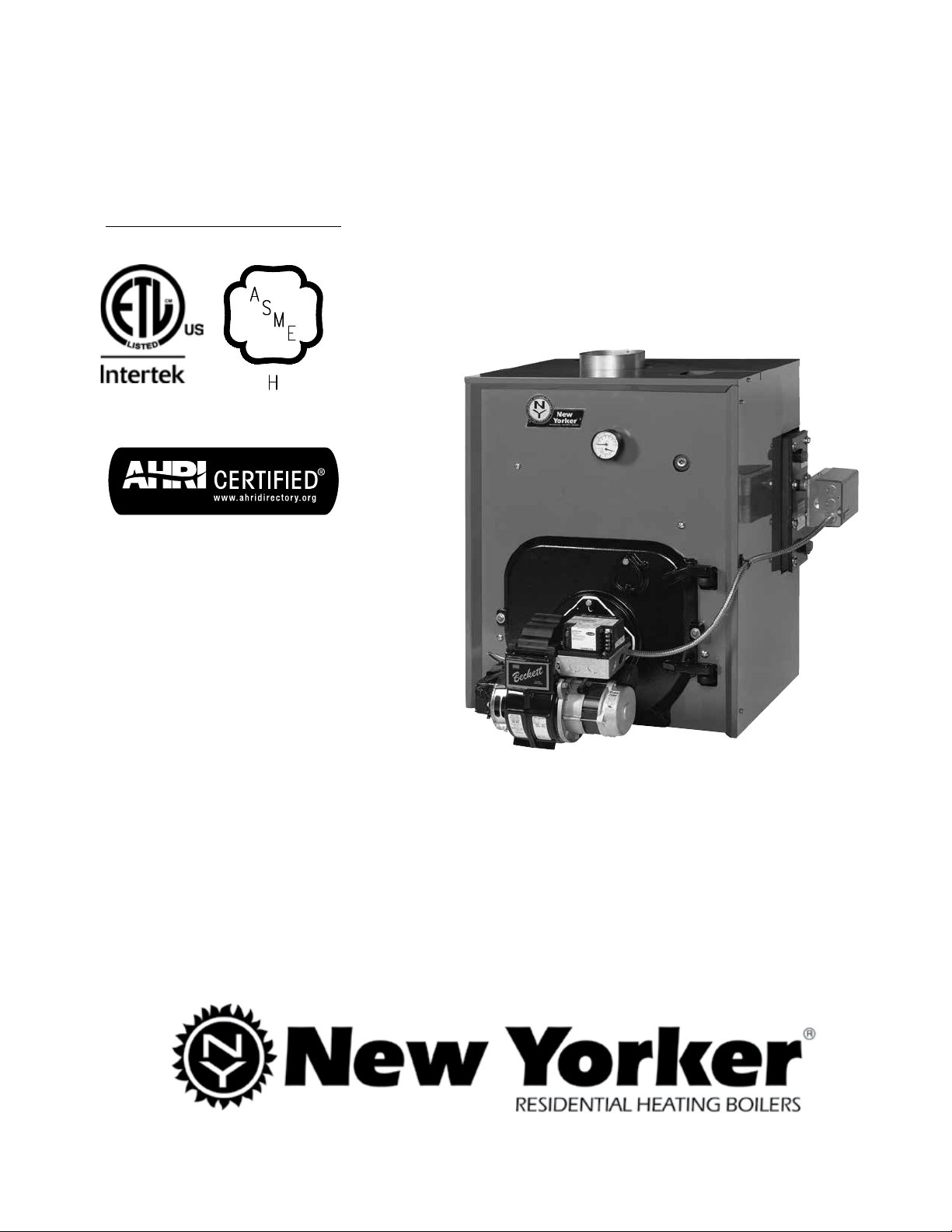
Installation, Operating and Service Instructions for
• Natural Draft
CL
9700609
Models:
• CL3-091W
• CL3-105-W
• CL3-140-W
• CL4-126-W
• CL4-175-W
• CL4-210-W
• CL5-168-W
• CL5-245-W
• CL5-230-W
TM
• CL3-091S
• CL3-105S
• CL3-140S
• CL4-126S
• CL4-175S
• CL4-210S
• CL5-168S
• CL5-245S
• CL5-280S
• Oil-Fired
• Water & Steam Boiler
TO THE INSTALLER:
Affix these instructions adjacent to boiler.
TO THE CONSUMER:
Retain these instructions for future reference.
For service or repairs to boiler, call your heating contractor. When seeking information on boiler, provide
Boiler Model Number and Serial Number as shown on Rating Label.
103876-08 - 1/19
Page 2
CL Installation & Service Manual
IMPORTANT INFORMATION - READ CAREFULLY
All boilers must be installed in accordance with National, State and Local Plumbing,
Heating and Electrical Codes and the regulations of the serving utilities. These
Codes and Regulations may differ from this instruction manual. Authorities having
jurisdiction should be consulted before installations are made.
In all cases, reference should be made to the following Standards:
USA BOILERS
A. Current Edition of American National Standard ANSI/NFPA 31, “Installation of Oil
Burning Equipment”, for recommended installation practices.
B. Current Edition of American National Standard ANSI/NFPA 211, “Chimneys, Fire
places, Vents, and Solid Fuel Burning Appliances”, For Venting requirements.
C. Current Edition of American Society of Mechanical Engineers ASME CSD-1,
“Controls and Safety Devices for Automatically Fired Boilers”, for assembly and
operations of controls and safety devices.
D. All wiring on boilers installed in the USA shall be made in accordance with the
National Electrical Code and/or Local Regulations.
The following terms are used throughout this manual to bring attention to the
presence of hazards of various risk levels, or to important information concerning
product life.
NOTICE This boiler has a limited warranty, a copy of which is included with this boiler. The warranty for
Surface rust on cast iron sections may be attributed to the manufacturing process as well as
DANGER
hazardous situation which, if not avoided, will
result in death, serious injury or substantial
property damage.
WARNING
hazardous situation which, if not avoided,
could result in death, serious injury or
substantial property damage.
this boiler is valid only if the boiler has been installed, maintained and operated in accordance with these
instructions.
condensation during storage. Surface rust is normal and does not affect the performance or longevity of
a boiler.
Indicates an imminently
Indicates a potentially
CAUTION
hazardous situation which, if not avoided, may
result in moderate or minor injury or property
damage.
NOTICE Indicates special instructions on
installation, operation, or maintenance which
are important but not related to personal injury
hazards.
Indicates a potentially
2
103876-08 - 1/19
Page 3
CL
• This boiler requires regular maintenance and service to operate safely. Follow the instructions contained
• Installation, maintenance, and service must be performed only by an experienced, skilled and
• All heating systems should be designed by competent contractors and only persons knowledgeable in
• Installation is not complete unless a pressure relief valve is installed into the tapping located on top left
• It is the responsibility of the installing contractor to see that all controls are correctly installed and are
Failure to properly install Limit Sensor may result in property damage, personal injury or loss of life due to
elevated operating temperatures and/or pressures.
• This boiler is suitable for installation on combustible flooring. Do not install boiler on carpeting.
• Do not tamper with or alter the boiler or controls.
• Inspect flueways at least once a year - preferably at the start of the heating season. The inside of
• When cleaning this boiler, DO NOT damage combustion chamber liner and/or rear target wall. If damaged,
• Oil Burner and Controls must be checked at least once a year or as may be necessitated.
• Do not operate boiler with jumpered or absent controls or safety devices.
• Do not operate boiler if any control, switch, component, or device has been subject to water.
• Boiler materials of construction, products of combustion and the fuel contain alumina, silica, heavy
DANGER
or any other appliance.
WARNING
property damage, personal injury or loss of life. Failure to follow all instructions in the proper order
can cause personal injury or death. Read and understand all instructions, including all those contained
in component manufacturers manuals which are provided with the boiler before installing, starting-up,
operating, maintaining or servicing this boiler. Keep this manual and literature in legible condition and
posted near boiler for reference by owner and service technician.
in this manual.
knowledgeable installer or service agency.
the layout and installation of hydronic heating systems should attempt installation of any boiler.
corner of front section- Refer to Figures 1A thru 1C and Section III "Installation Instructions" for additional
details.
operating properly when installation is complete including verifying that the limit sensor is fully installed
(seated in bottom of Well).
the combustion chamber, the vent system and boiler flueways should be cleaned if soot or scale has
accumulated.
combustion chamber insulation must be replaced immediately.
metals, carbon monoxide, nitrogen oxides, aldehydes and/or other toxic or harmful substances which
can cause death or serious injury and which are known to the state of California to cause cancer, birth
defects and other reproductive harm. Always use proper safety clothing, respirators and equipment when
servicing or working nearby the boiler.
DO NOT store or use gasoline or other flammable vapors or liquids in the vicinity of this
Improper installation, adjustment, alteration, service or maintenance can cause
Installation & Service Manual
103876-08 - 1/19
3
Page 4
CL Installation & Service Manual
WARNING
fittings nor attempt to disconnect any components of this boiler without positively assuring the water is
cool and has no pressure. Always wear protective clothing and equipment when installing, starting up
or servicing this boiler to prevent scald injuries. Do not rely on the pressure and temperature gauges to
determine the temperature and pressure of the boiler. This boiler contains components which become
very hot when the boiler is operating. Do not touch any components unless they are cool.
• High water temperatures increase the risk of scalding injury. If this boiler is equipped with a tankless
heater for domestic water supply, a flow regulator and automatic mixing valve must be installed properly
in tankless heater piping. See Piping and Trim Sections of this manual for details.
• This boiler must be properly vented and connected to an approved vent system in good condition. DO
NOT operate boiler with the absence of an approved vent system.
• This boiler needs fresh air for safe operation and must be installed so there are provisions for adequate
combustion and ventilation air.
• This boiler must be connected to an approved chimney or vent system in good condition. Serious
property damage could result if the boiler is connected to a dirty or inadequate chimney or vent system.
The interior of the chimney flue must be inspected and cleaned before the start of the heating season for
any obstructions. A clean and unobstructed chimney flue is necessary to allow noxious fumes that could
cause injury or loss of life to vent safely and will contribute toward maintaining the boiler's efficiency. DO
NOT operate boiler with the absence of an approved vent system.
• This boiler is supplied with controls which may cause the boiler to shut down and not re-start without
service. If damage due to frozen pipes is a possibility, the heating system should not be left unattended in
cold weather; or appropriate safeguards and alarms should be installed on the heating system to prevent
damage if the boiler is inoperative.
• This boiler is designed to burn No. 2 fuel oil only. DO NOT use gasoline, crankcase drainings, or any oil
containing gasoline. Never burn garbage or paper in this boiler. DO NOT convert to any solid fuel (i.e.
wood, coal). DO NOT convert to any gaseous fuel (i.e. natural gas, LP). All flammable debris, rags, paper,
wood scraps, etc., should be kept clear of the boiler at all times. Keep the boiler area clean and free of fire
hazards.
• All boilers equipped with burner swing door have a potential hazard which if ignored can cause severe
property damage, personal injury or loss of life. Before opening swing door, turn off service switch to
boiler to prevent accidental firing of burner outside the combustion chamber. Be sure to tighten swing
door fastener completely when service is completed.
This boiler contains very hot water under high pressure. Do not unscrew any pipe
Table of Contents
I. General Information ..................................... 5
II. Pre-Installation ............................................10
III. Installation Instructions............................... 12
IV. Electrical..................................................... 26
V. System Start-Up ......................................... 32
VI. Operating ................................................... 38
VII. Maintenance & Service Instructions. .........44
4
VIII. Boiler Cleaning .......................................... 47
IX. Trouble Shooting .......................................50
X. Repair Parts ..............................................53
XI. Burner Specifications ................................ 61
Appendix A - Aftermarket Low Water
Cut-Off ......................................................64
103876-08 - 1/19
Page 5
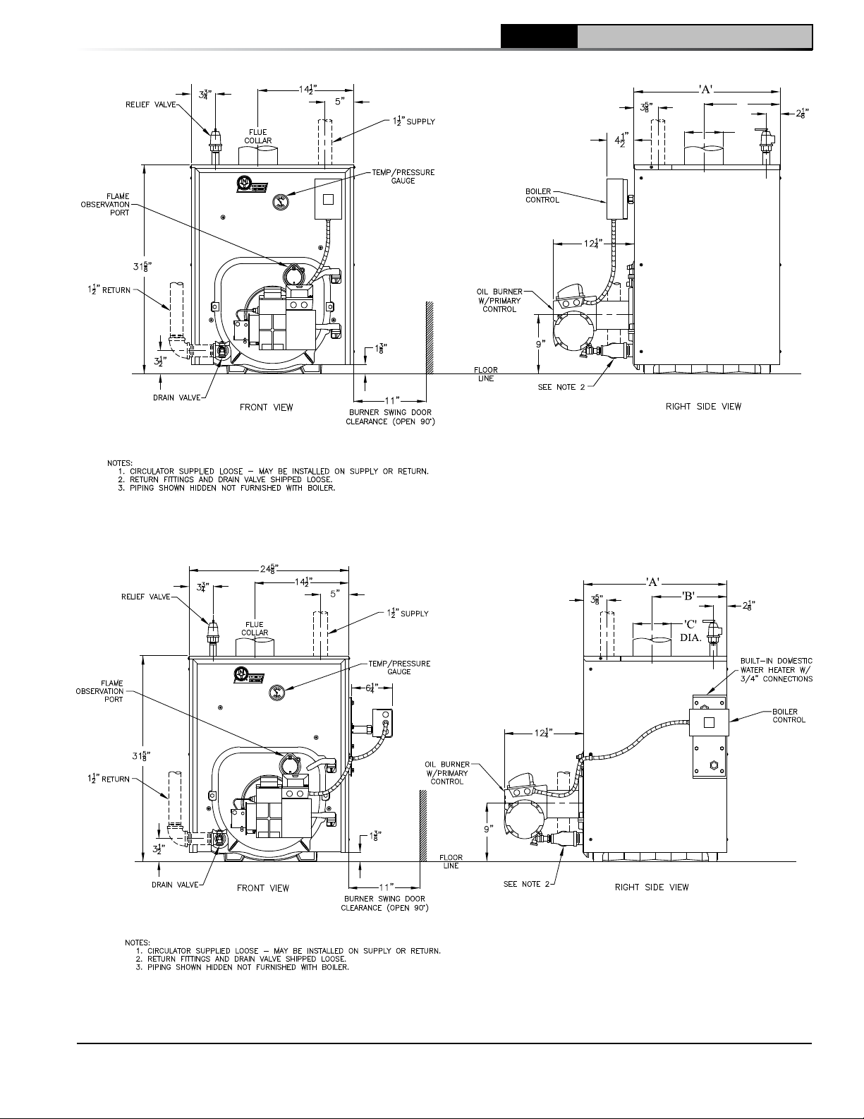
1 General Information
CL
Installation & Service Manual
'B'
'C'
DIA.
NOTE: For Carlin Burners Only: Burner extends in front of boiler 11-1/4", burner swing door clearance is 10", burner extends 2-5/8" above floor and burner is not available with cover.
Figure 1A: CL3 Thru CL5 Water Boiler without Tankless Heater, All Burner Options
NOTE: For Carlin Burners Only: Burner extends in front of boiler 11-1/4", burner swing door clearance is 10",
burner extends 2-5/8" above floor and burner is not available with cover.
Figure 1B: CL3 Thru CL5 Water Boiler With Tankless Heater, All Burner Options
103876-08 - 1/19
5
Page 6
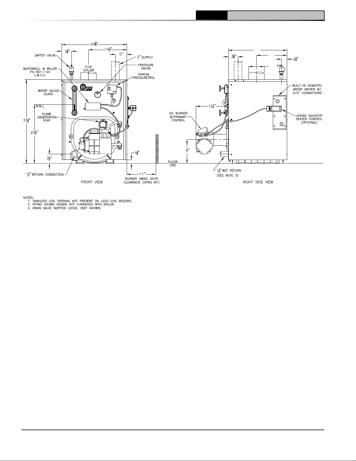
1 General Information (continued)
CL Installation & Service Manual
'A'
'B'
'C'
DIA.
NOTE: For Carlin Burners Only: Burner extends in front of boiler 11-1/4", burner swing door clearance is 10", burner extends 2-5/8" above floor and burner is not available with cover.
Figure 1C: CL3 Thru CL5 Steam Boiler with or without Tankless Heater,
McDonnell & Miller PSE-801, Beckett and Carlin Burners
6
103876-08 - 1/19
Page 7
CL
1 General Information (continued)
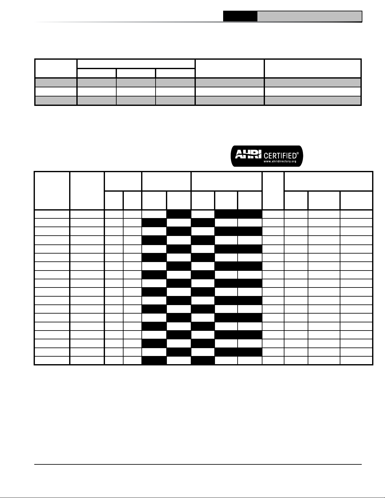
Table 1: Dimensional Data / General Information (See Figures 1A Thru 1C)
Installation & Service Manual
Boiler Series
CL3 17-3/8" 8-1/4" 5-7/8" 16 14.33
CL4 22-3/8" 10-7/8" 6-7/8" 20 20.90
CL5 27-3/8" 13-3/8" 7-7/8" 24 27.46
"A" "B" "C"
Dimensions
Approx. Water Content
- Gallons
Heat Transfer Surface Area - Sq.
Ft.
Maximum Working Pressure: Steam: 15 PSI; Water: 30 PSI Shipped Standard from Factory, 50 PSI Optional
Table 2: Rating Data
Burner
Boiler
Series
Boiler
Model
Capacity
GPH MBH
CL3-091(W) CL3-091-W 0.65 91 80 70 86.1 6 8 x 8 15
CL3-091(S) CL3-091S 0.65 91 78 59 233 84.1 6 8 x 8 15
CL3-105(W) CL3-105-W 0.75 105 92 80 86.0 6 8 x 8 15
CL3-105(S) CL3-105S 0.75 105 90 68 283 83.8 6 8 x 8 15
CL3-140(W) CL3-140-W 1.00 140 120 104 84.3 6 8 x 8 15
CL3-140(S) CL3-140S 1.00 140 119 89 370 82.7 6 8 x 8 15
CL4-126(W) CL4-126-W 0.90 126 111 97 86.0 7 8 x 8 15
CL4-126(S) CL4-126S 0.90 126 108 81 338 84.1 7 8 x 8 15
CL4-175(W) CL4-175-W 1.25 175 151 131 85.1 7 8 x 8 15
CL4-175(S) CL4-175S 1.25 175 149 112 467 83.5 7 8 x 8 15
CL4-210(W) CL4-210-W 1.50 210 179 156 84.0 7 8 x 8 15
CL4-210(S) CL4-210S 1.50 210 177 133 554 82.6 7 8 x 8 15
CL5-168(W) CL5-168-W 1.20 168 147 128 85.9 8 8 x 8 15
CL5-168(S) CL5-168S 1.20 168 144 108 450 83.7 8 8 x 8 15
CL5-245(W) CL5-245-W 1.75 245 212 184 85.1 8 8 x 8 15
CL5-245(S) CL5-245S 1.75 245 207 155 646 82.5 8 8 x 8 15
CL5-280(W) CL5-280-W 2.00 280 241 210 84.7 8 8 x 8 15
CL5-280(S) CL5-280S 2.00 280 235 176 733 82.3 8 8 x 8 15
(1)
MBH refers to thousands of BTU per hour.
(2)
Based on standard test procedure prescribed by the United States Department of Energy at combustion
Heating
Capacity
Water
MBH
(1)
(2)
Steam
MBH
Net AHRI Ratings
Water
MBH
Steam
MBH
(3)
Steam
Sq. Ft.
AFUE
%
Minimum Chimney
Requirements
Round
In. Dia.
Rectangle
In. x In.
Height Ft.
conditions of 12.5% CO2.
(3)
Net AHRI Ratings are based on piping and pickup allowance of 1.15 for water and 1.333 for steam.
103876-08 - 1/19
7
Page 8
1 General Information (continued)
CL Installation & Service Manual
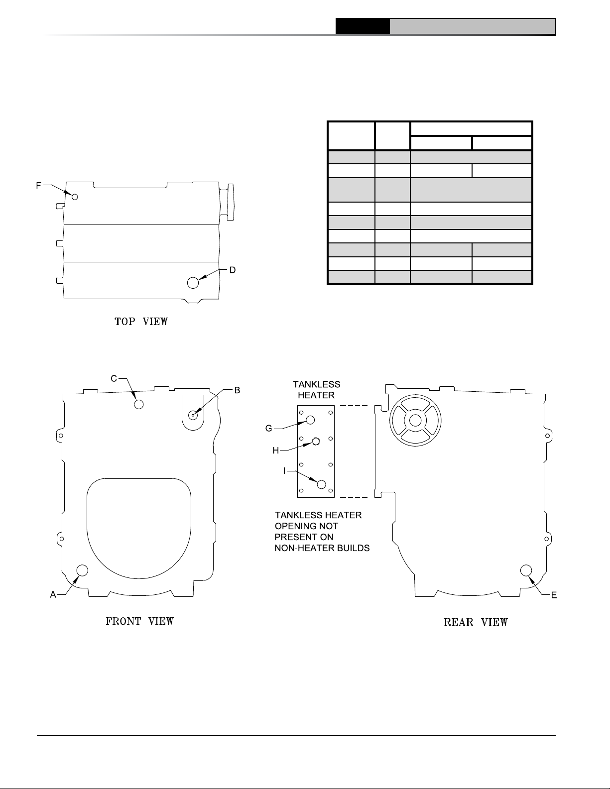
Table 3A: Purpose of Tappings (Water)
Tapping
Location
A 1½” Return
B ½” Limit Well Plug
C ¼”
D 1½” Supply
E 1½” Optional Return
F ¾” Relief Valve
G ¾” N/A DHW Outlet
H ¾” N/A Limit Well
I ¾” N/A DHW Inlet
Size,
NPT
Less Heater With Heater
Purpose
Temperature/Pressure
Gauge
Figure 2A: Purpose of Tappings (Water)
8
103876-08 - 1/19
Page 9
1 General Information (continued)
CL
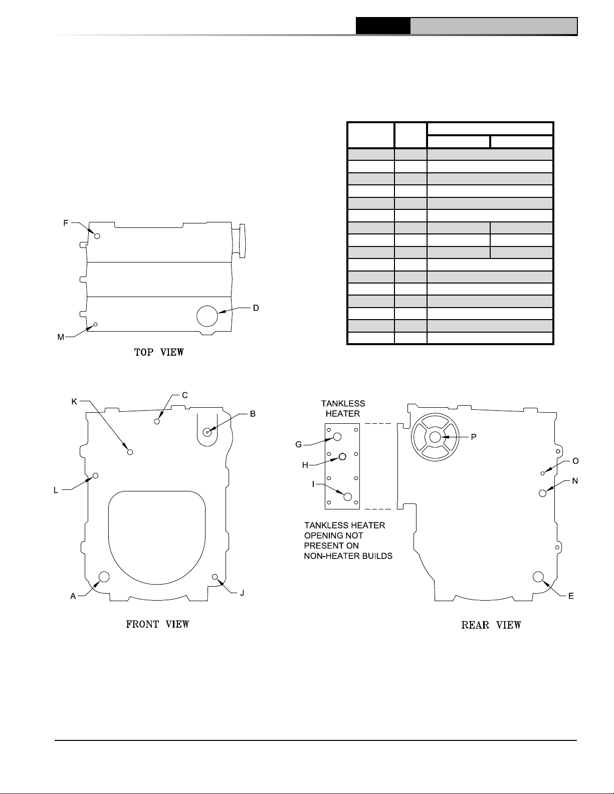
Table 3B: Purpose of Tappings (Steam)
Installation & Service Manual
Tapping
Location
A 1½” Return
B ½” Pressure Limit
C ¼” Pressure Gauge
D 3” Supply
E 1½” Optional Return
F ¾” Relief Valve
G ¾” N/A DHW Outlet
H ¾” N/A Limit Well
I ¾” N/A DHW Inlet
J ¾” Drain
K ¾” LWCO
L ½” Water Gauge Glass
M ½” Water Gauge Glass
N 1” Indirect Water Heater Supply
O ½” Indirect Water Heater Limit
P 1½” Surface Blowoff
Size,
NPT
Less Heater With Heater
Purpose
103876-08 - 1/19
Figure 2B: Purpose of Tappings (Steam)
9
Page 10
2 Pre-Installation (continued)
CL Installation & Service Manual
A. INSPECT SHIPMENT carefully for any signs of
damage.
1. All equipment is carefully manufactured,
inspected and packed. Our responsibility
ceases upon delivery of crated boiler to the
carrier in good condition.
2. Any claims for damage or shortage in
shipment must be filed immediately against
the carrier by the consignee. No claims for
variances from, or shortage in orders, will be
allowed by the manufacturer unless presented
within sixty (60) days after receipt of goods.
B. LOCATE BOILER near final position before
removing crate. See Figures 1A thru 1C. Using
hand truck or pipe rollers under skid, move boiler
into position along side installation site.
1. Locate so that vent pipe connection to
chimney will be short and direct.
2. Boiler is suitable for installation on combustible
floor. Boiler cannot be installed on carpeting.
3. For basement installation, provide a solid
elevated base, such as concrete, if floor is not
level, or if water may be encountered on floor
around boiler.
4. Provide service clearance of at least 24”
clearance from front jacket panel for servicing
and removal of front tankless heater. If boiler is
equipped with a rear tankless heater, provide
at least 24" service clearance on the right side
of the boiler. Boiler flueways may be cleaned
either from the top or from the right side.
Provide at least 24" clearance from either the
right side of the boiler or the top of the boiler
for cleaning flueways.
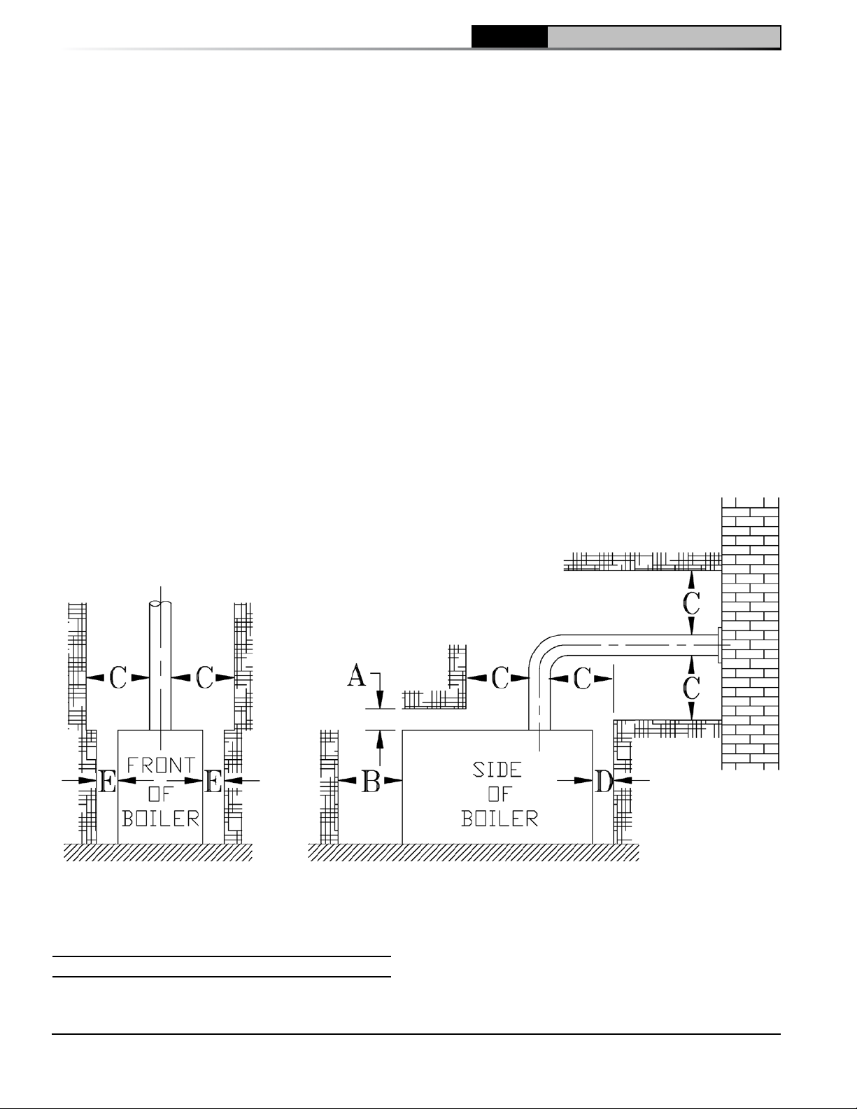
5. For minimum clearances to combustible
materials. See Figure 3.
NOTICE Clearance to venting is for single wall
vent pipe. If Type L vent is used, clearance
may be reduced to the minimum required by
the vent pipe manufacturer.
C. PROVIDE COMBUSTION AND VENTILATION AIR.
Local and National Codes may apply and should
be referenced.
Figure 3: Minimum Installation Clearances To Combustible Materials (Inches)
C
A
Above
6 24 18 6 6
NOTE 1: Listed clearances comply with American National
Standard NFPA 31, Standard for the Installation of Oil
Burning Equipment.
B
Front
Chimney
Connector
D
Rear
E
Sides
10
NOTE 2: CL Series boilers can be installed in rooms with
clearances from combustible material as listed above.
Listed clearances cannot be reduced for alcove or closet
installations.
NOTE 3: For reduced clearances to combustible material,
protection must be provided as described in the ANSI/NFPA
31 standard.
103876-08 - 1/19
Page 11
2 Pre-Installation (continued)
CL
Installation & Service Manual
WARNING
ventilation air must be provided to assure
proper combustion and to maintain safe
ambient air temperatures.
DO NOT install boiler where gasoline or other
flammable vapors or liquids, or sources of
hydrocarbons (i.e. bleaches, fabric softeners,
etc.) are used or stored.
1. Determine volume of space (boiler room).
Rooms communicating directly with the
space in which the appliances are installed,
through openings not furnished with doors, are
considered a part of the space.
Volume(ft3) = Length(ft) x Width(ft) x Height(ft)
2. Determine total input of all appliances in the
space.
Add inputs of all appliances in the space and
round the result to the nearest 1000 BTU per
hour.
3. Determine type of space. Divide Volume by
total input of all appliances in space. If the
result is greater than or equal to 50 ft
BTU per hour, then it is considered an
unconfined space. If the result is less than
50 ft3/1000 BTU per hour then the space is
considered a confined space.
4. For boiler located in an unconfined space of a
conventionally constructed building, the fresh
air infiltration through cracks around windows
and doors normally provides adequate air for
combustion and ventilation.
5. For boiler located in a confined space or an
unconfined space in a building of unusually
tight construction, provide outdoor air.
Outdoor air may be provided with the use of
two permanent openings which communicate
directly or by duct with the outdoors or spaces
(crawl or attic) freely communicating with the
outdoors. Locate one opening within 12 inches
of top of space.
Locate remaining opening within 12 inches of
bottom of space. Minimum dimension of air
opening is 3 inches. Size each opening per
following:
a. Direct communication with outdoors.
Minimum free area of 1 square inch per
4,000 BTU per hour input of all equipment in
space.
Adequate combustion and
3
/1000
b. Vertical ducts. Minimum free area of 1
square inch per 4,000 BTU per hour input
of all equipment in space. Duct crosssectional area shall be same as opening
free area.
c. Horizontal ducts. Minimum free area of 1
square inch per 2,000 BTU per hour input
of all equipment in space. Duct crosssectional area shall be same as opening
free area.
Alternate method for boiler located within
confined space. Use indoor air if two
permanent openings communicate directly
with additional space(s) of sufficient volume
such that combined volume of all spaces
meet criteria for unconfined space. Size
each opening for minimum free area of 1
square inch per 1,000 BTU per hour input of
all equipment in spaces, but not less than
100 square inches.
6. Louvers and Grilles of Ventilation Ducts
a. All outside openings should be screened
and louvered. Screens used should not be
smaller than 1/4 inch mesh. Louvers will
prevent the entrance of rain and snow.
b. Free area requirements need to consider
the blocking effect of louvers, grilles, or
screens protecting the openings. If the free
area of the louver or grille is not known,
assume wood louvers have 20-25 percent
free area and metal louvers and grilles have
60-75 percent free area.
c. Louvers and grilles must be fixed in the
open position, or interlocked with the
equipment to open automatically during
equipment operation.
103876-08 - 1/19
11
Page 12
3 Installation Instructions
A. REMOVE CRATE.
1. Remove all fasteners at crate skid.
2. Lift outside container and remove all other
inside protective spacers and bracing.
Remove miscellaneous steam or water trim
carton.
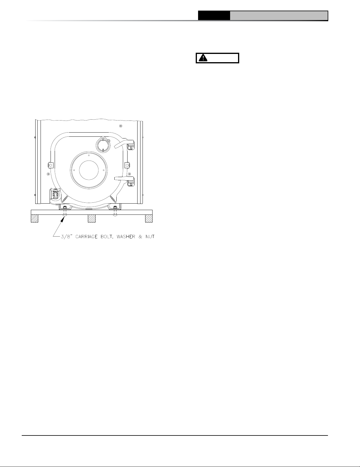
B. REMOVAL OF BOILER FROM SKID.
1. Boiler is secured to base with 4 carriage bolts,
2 on left side and 2 on right side. See Figure
4. Remove all bolts.
Figure 4: Removal of Boiler From Skid
2. Tilt boiler to right and to rear. Using right rear
leg as pivot, rotate boiler 90° in a clockwise
direction, and lower left side of boiler to floor.
Tilt boiler and remove crate skid. Care should
be exercised to prevent damage to jacket or
burner.
C. MOVE BOILER TO PERMANENT POSITION by
sliding or walking.
D. INSPECT COMBUSTION TARGET WALL AND
COMBUSTION CHAMBER LINER.
1. Open flame observation door and/or burner
swing door on front of boiler. Use flashlight to
inspect target wall secured to rear section with
silastic sealant. Inspect ceramic fiber blanket
secured to floor of boiler with water glass
adhesive. If either is damaged they must be
replaced.
E. INSTALL OIL BURNER.
1. Open burner carton and remove contents.
Refer to Tables 14A, 14B and 14C as well as
the burner parts table on page 60 for proper
burner specification.
CL Installation & Service Manual
2. Place oil burner gasket on burner and align
holes.
CAUTION
Gasket.
3. Remove four (4) 5/16-18 x 3/4” long cap
screws from burner swing door used for
mounting burner.
4. Insert oil burner into opening of burner swing
door. Align the top slotted hole in burner
flange with the top hole on the burner swing
door. Install one (1) cap screw.
5. Align remaining holes and install the three (3)
remaining cap screws.
F. INSPECT NOZZLE, ELECTRODES INSERTION
DEPTH AND TURBULATOR SETTING/CHANGE
FIRING RATE:
1. CL™ Series boilers are shipped with the
highest input oil nozzle installed in the burner.
Oil nozzles for lower firing rates are shipped
loose attached to the burner. Select the proper
oil nozzle for the installation. The lower input
nozzle will provide greater boiler efficiency.
However, boiler output will be reduced. Refer
to Table 2 for firing rates.
2. On the Beckett AFG Burner, use the following
procedure to complete the inspection, check
the settings and to change the nozzle to a
lower firing rate:
a. Loosen two (2) igniter latching screws,
rotate tabs and swing open igniter about
hinge.
b. Loosen knurled nut and disconnect copper
connector tube.
c. Remove nozzle line electrode assembly.
d. If high firing rate is desired, confirm the
nozzle is the proper size and type, refer
to Table 14A (at rear of this manual), then
proceed to Item i. below.
e. If a lower input is desired, remove the
nozzle that was factory installed.
f. Remove Beckett MB(L1) or MD(V1) head.
g. Locate the desired nozzle. Refer to Table
14A (at rear of this manual) for proper
nozzle. The nozzle must be securely
installed to assure leak free joints between
the nozzle and adapter. When installing the
nozzle, be careful not to bump or move the
burner electrodes.
Note: On the CL3-091 (0.65 GPH) burner
application, a low firing rate baffle is
required. Baffle is shipped loose with
nozzles. Install baffle per Beckett
Do not install burner without
12
103876-08 - 1/19
Page 13
CL
Installation & Service Manual
3 Installation Instructions (continued)
Instruction included with baffle.
h. Reinstall Beckett MB(L1) or MD(V1) Head.
i. Inspect and measure burner electrodes.
Refer to Figure 27 for the proper electrode
setting. Readjust electrode setting to the
proper dimensions if necessary. Refer to
Figure 27.
j. Reinstall nozzle line electrode assembly.
k. Connect copper connector tube.
l. Inspect Beckett head setting on left side
of burner by insuring the line on the label
MB(L1) or the blue line MD(V1) are aligned,
readjust if necessary. Refer to Figure 27.
m. Tighten knurled nut.
n. Swing igniter closed, rotate tabs and tighten
two (2) igniter screws.
3. On the Riello 40 Series Oil Burner, use
the following procedure to complete the
inspection, check the settings and to change
the nozzle to a lower firing rate: Refer also to
Model F3 & F5 Installation Manual, Riello 40
Series Residential Oil Burners (C6501010) or
Model F10 Installation Manual, Riello 40 Series
Residential Oil Burners No. 2902554.
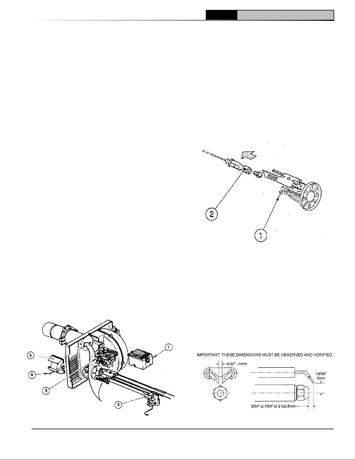
a. Installation/Removal of Drawer Assembly,
refer to Figure 5.
i. Removal:
• Disconnect oil delivery tube nut from
pump.
• Loosen SCREW (3), and then unplug
PRIMARY CONTROL (1) by carefully
pulling it back and then up.
• Remove the AIR TUBE COVER
PLATE (5) by loosening the retaining
SCREW (4) (Two SCREWS-Model F5).
• Loosen SCREW (2), and then slide
the complete drawer assembly out of
the combustion head as shown.
ii. Installation:
To insert drawer assembly, reverse the
procedure in Step i above.
b. Nozzle Replacement, refer to Figure 6.
i. Remove the NOZZLE ADAPTER (2) from
the DRAWER ASSEMBLY by loosening
the SCREW (1).
ii. Remove existing nozzle from nozzle
adapter.
iii. Insert the proper NOZZLE into NOZZLE
ADAPTER and tighten securely (DO NOT
cover tighten), refer to Table 14B (at rear
of this manual).
iv. Replace adapter, with nozzle installed,
into drawer assembly and secure with
screw (1).
Figure 6: Riello Nozzle Replacement
c. Inspect and measure burner electrodes.
Refer to Figure 7 for the proper electrode
settings.
d. Re-install Drawer Assembly into Combustion
Head per Step 3a above.
e. Insertion Depth, verify the distance between
the tip of the end cone is equal to the
distance specified in Table 14B (at rear of
this manual).
f. Turbulator Setting, refer to Figure 8.
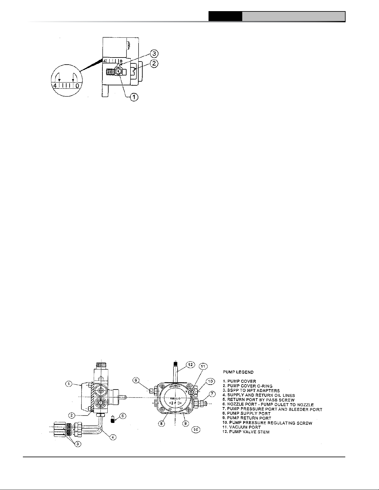
g. Pump Connections and Port Identification,
refer to Figure 9.
This burner is shipped with the oil pump
Figure 5: Installation/Removal of
Riello Drawer Assembly
103876-08 - 1/19
Figure 7: Riello Electrode Setting
13
Page 14
CL Installation & Service Manual
3 Installation Instructions (continued)
Figure 8: Riello Turbulator Setting
set to operate on a single line system. To
operate on a two-line system the bypass
plug must be installed.
WARNING: DO NOT operate a single line
system with the by-pass plug installed.
Operating a single line system with the bypass plug installed will result in damage to
the pump shaft seal.
Note: Pump pressure was factory pre-set but
must be checked at time of burner startup. A pressure gauge is attached to the
PRESSURE/BLEEDER PORT (7) for pressure
readings. Two PIPE CONNECTORS (4)
are supplied with the burner for connection
to either a single or two-line system. Also
supplied are two ADAPTORS (3), two
female ¼” NPT to adapt oil lines to burner
pipe connectors. All pump port threads
are British Parallel Thread design. Direct
connection of NPT threads to the pump will
damage the pump body.
Riello manometers and vacuum gauges
DO NOT require any adapters, and can be
safely connected to the pump ports. An
NPT x metric adapter must be used when
connecting other gauge models.
h. Replace Burner Cover and Tighten Burner
Cover Screws.
4. On the Carlin EZ-PH Burner, use the following
procedure to complete the inspection, check
the settings and to change the nozzle to a
lower firing rate:
a. Loosen two (2) igniter latching screws,
rotate tabs and swing open igniter about
hinge.
b. Loosen knurled nut and disconnect copper
connector tube.
c. Remove nozzle line electrode assembly
from burner.
d. If high firing rate is desired, confirm the
nozzle is the proper size and type, refer
to Table 14C (at rear of this manual), then
proceed to Item i.
e. If a lower input is desired, remove the flame
retention head and then remove the nozzle
that was factory installed.
f. Locate the desired nozzle, refer to Table
14C (at rear of this manual) for proper
nozzle. The nozzle must be securely
installed to assure leak free joints between
the nozzle and adapter. When installing the
nozzle, be careful not to bump or move the
burner electrodes.
g. Reinstall Flame Retention Head on Nozzle
Line Electrode Assembly. Make sure the
clamp is fully sated against the shoulder on
the nozzle adapter before securing.
h. Loosen and remove the retaining nut and
factory installed head bar from side of
burner housing. Install the proper head bar
that corresponds to the desired firing rate,
refer to Table 14C (at rear of this manual),
and tighten retaining nut.
i. Readjust air band to preliminary setting that
corresponds to the lower firing rate nozzle
installed, refer to Table 14C (at rear of this
manual).
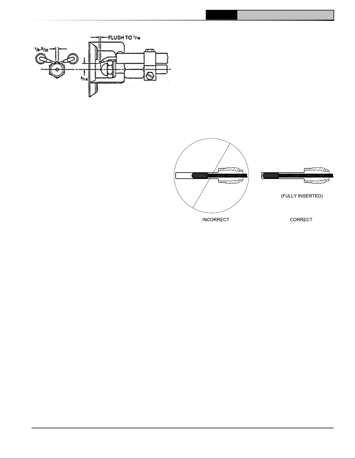
j. Inspect and measure burner electrodes.
Refer to Figure 10 for proper electrode
setting. Readjust electrode setting to the
proper dimensions if necessary.
k. Reinstall nozzle line electrode assembly.
l. Reconnect copper connector tube.
14
Figure 9: Riello Pump Connections and Port Identification
103876-08 - 1/19
Page 15
CL
Installation & Service Manual
3 Installation Instructions (continued)
Figure 10: Electrode Settings
m. Tighten knurled nut.
n. Close igniter, rotate and tighten two (2)
igniter latching screws.
G. INSTALL WATER BOILER TRIM AND CONTROLS,
(see Figures 1A and 1B).
1. Install return piping supplied with boiler. Apply
Teflon or Sealant to all joints prior to assembly.
Thread 1½" NPT x 5" Lg. return nipple into 1½"
NPT tapping located in lower left corner of
front section. Thread 1½" x ¾" x 1½" NPT tee
onto 5" nipple. Thread ¾" drain valve into ¾"
NPT connection on tee. Tighten all joints with
wrench until water tight and 1½" NPT return
connection on tee is facing away from boiler
horizontally to allow for proper burner swing
door clearance, see Figures 1A, 1B, 12A and
12B.
Note: Vertical piping will prevent door from
opening fully for service and cleaning of boiler.
2. Thread relief valve onto factory installed ¾"
NPT x 7¼" nipple located in left rear corner
on top of boiler as shown in Figures 1A and
1B. Valve spindle must be in vertical position.
Tighten with wrench. Pipe discharge as shown
in Figures 12A and 12B. Installation of the
relief valve must be consistent with ANSI/ASME
Boiler and Pressure Vessel Code, Section IV.
3. Connect Field Wiring
Connect the field wiring to the Warm or Cold
Start Intelligent Oil Boiler Control (Boiler
Control). Make the wiring connections as
shown in Figure 21 and 22.
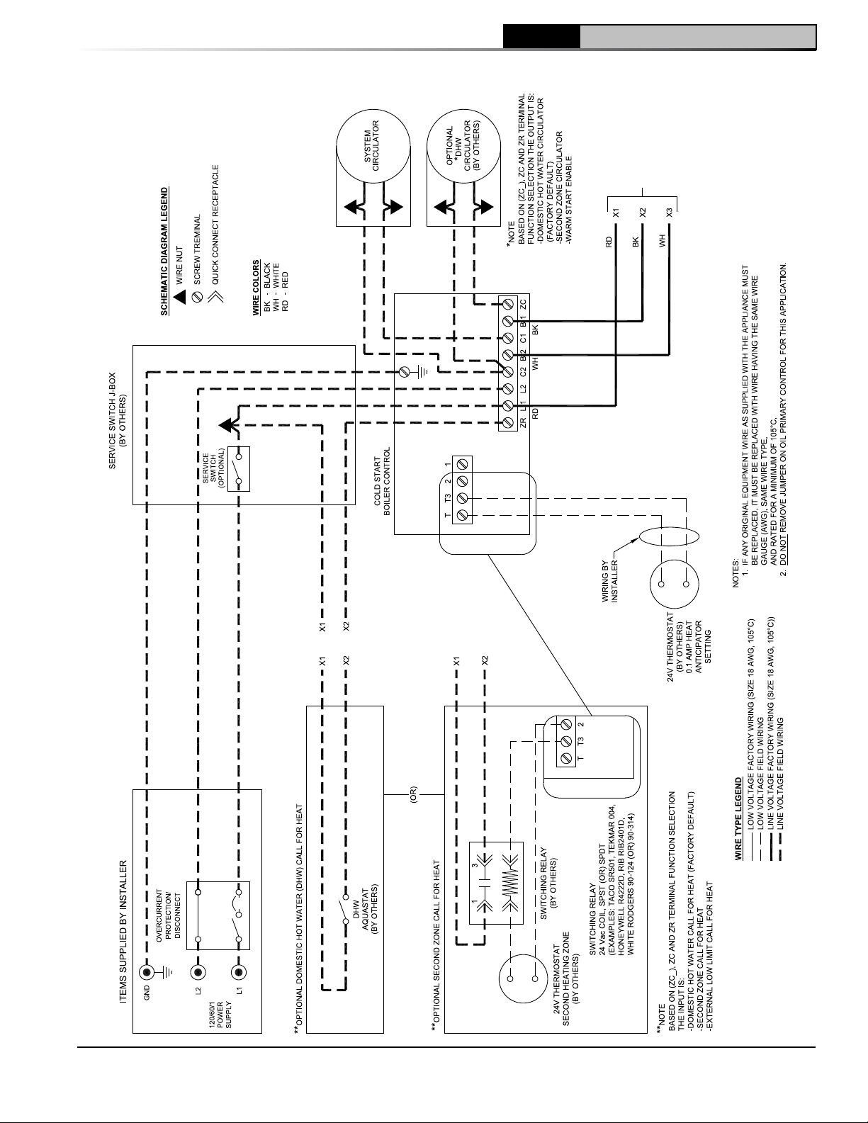
a. On water boilers without rear tankless
heater, connect the field wiring from the
circulator to the Cold Start Boiler Control
and from the Cold Start Boiler Control to the
Burner Oil Primary Control. Make the wiring
connections as shown on Figure 21.
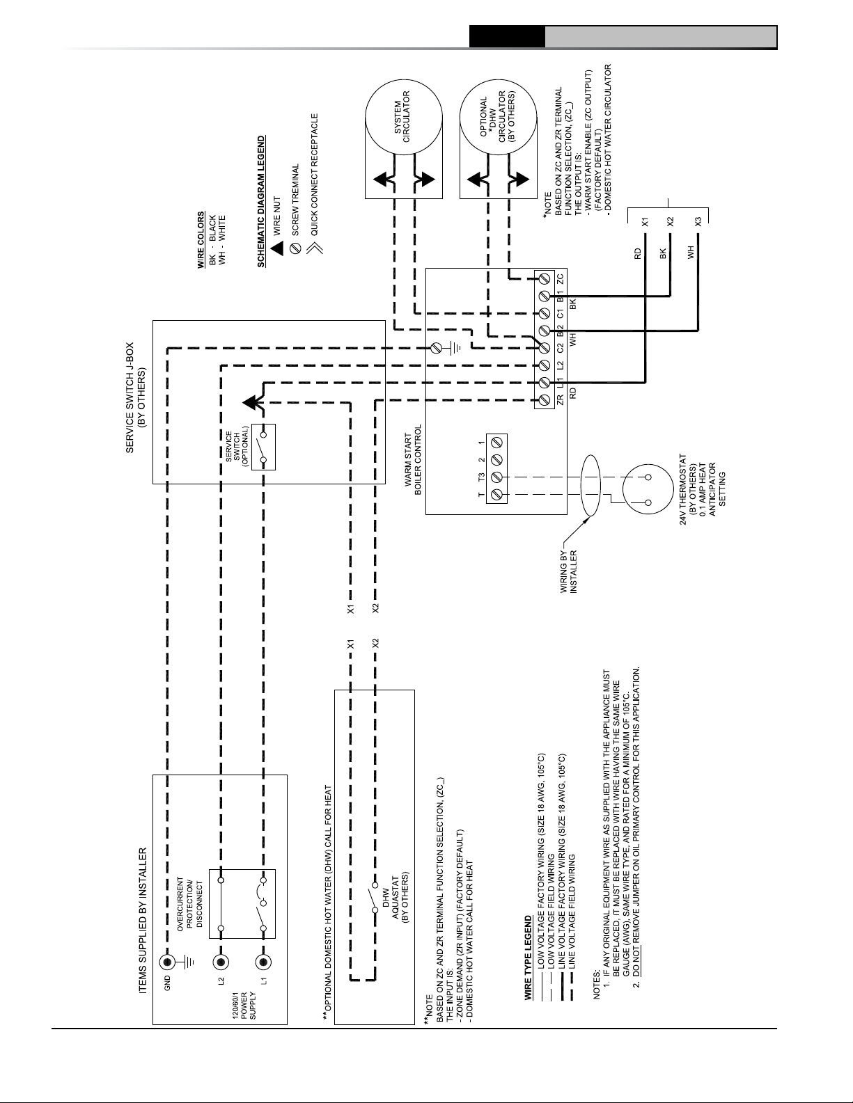
b. On water boilers with rear tankless heater,
the factory wired Warm Start Boiler Control
was not installed in heater. Locate 3/4" NPT
immersion well, apply sealant, thread into
3/4" NPT tapping on tankless heater and
103876-08 - 1/19
tighten with wrench. Apply heat transfer
paste (not furnished) to limit sensor and
fully insert limit sensor into immersion well
such that the tip on the limit sensor touches
the bottom of the immersion well. See
Figure 11. Tighten clamp screws to secure
Warm Start Boiler Control to immersion well.
Secure Boiler Control conduit to jacket right
side panel with 5/8" cable clamp provided,
refer to Figure 1B. Make the wiring
connections as shown on Figure 22.
H. INSTALL STEAM BOILER TRIM AND CONTROLS,
(see Figure 1C).
1. Thread ¾" MPT safety valve and ¾" NPT
coupling onto factory installed ¾" NPT x
Figure 11: Limit Sensor Insertion
7¼" nipple located in left rear corner on top
of boiler as shown in Figure 1C. Tighten
with wrench. Pipe discharge as shown in
Figure 13. Installation of the relief valve must
be consistent with ANSI/ASME Boiler and
Pressure Vessel Code, Section IV.
2. Install ¾" drain valve in wet return piping as
shown in Figure 13.
3. On boilers with rear tankless heater, factory
wired L4006A Aquastat Heater Control was not
installed in heater. Locate ¾" NPT Immersion
Well, apply sealant and thread into ¾" NPT
tapping on heater. Apply heat transfer paste
(not furnished) to control bulb and insert bulb
into immersion well. Tighten clamping screws
to secure Boiler Control to immersion well.
Secure 18/2 Control Cable Wire to jacket right
side panel with 5/16" cable clamp provided,
refer to Figure 1C.
4. Connect Field Wiring
a. Connect the field wiring to the pressure
limit, the LWCO and the burner or primary
control. If equipped with tankless heater,
connect field wiring from the Aquastat
Control to the Oil Primary Control "TT"
terminals. Make the wiring connections as
shown in Figure 23.
15
Page 16
3 Installation Instructions (continued)
CL Installation & Service Manual
16
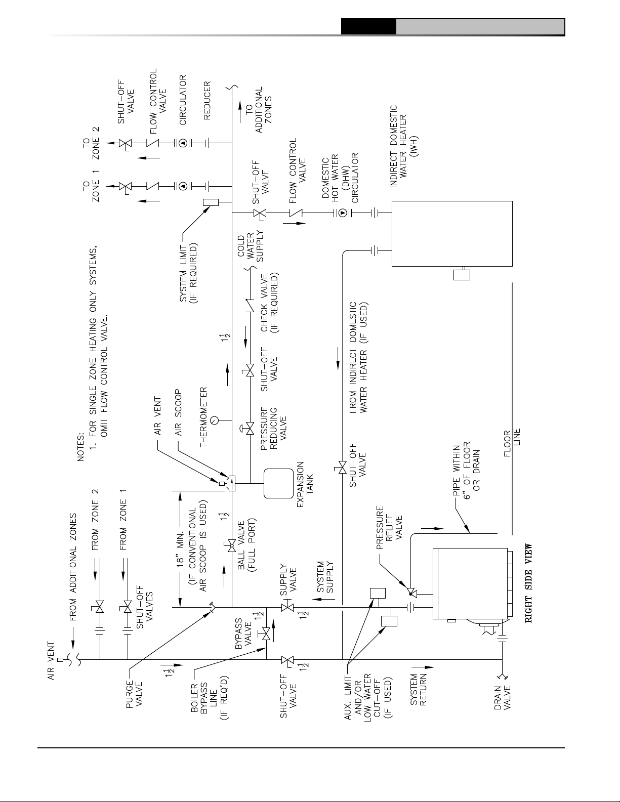
Figure 12A: Recommended Water Piping for Circulator Zoned Heating System - Supply Side Circulator
103876-08 - 1/19
Page 17
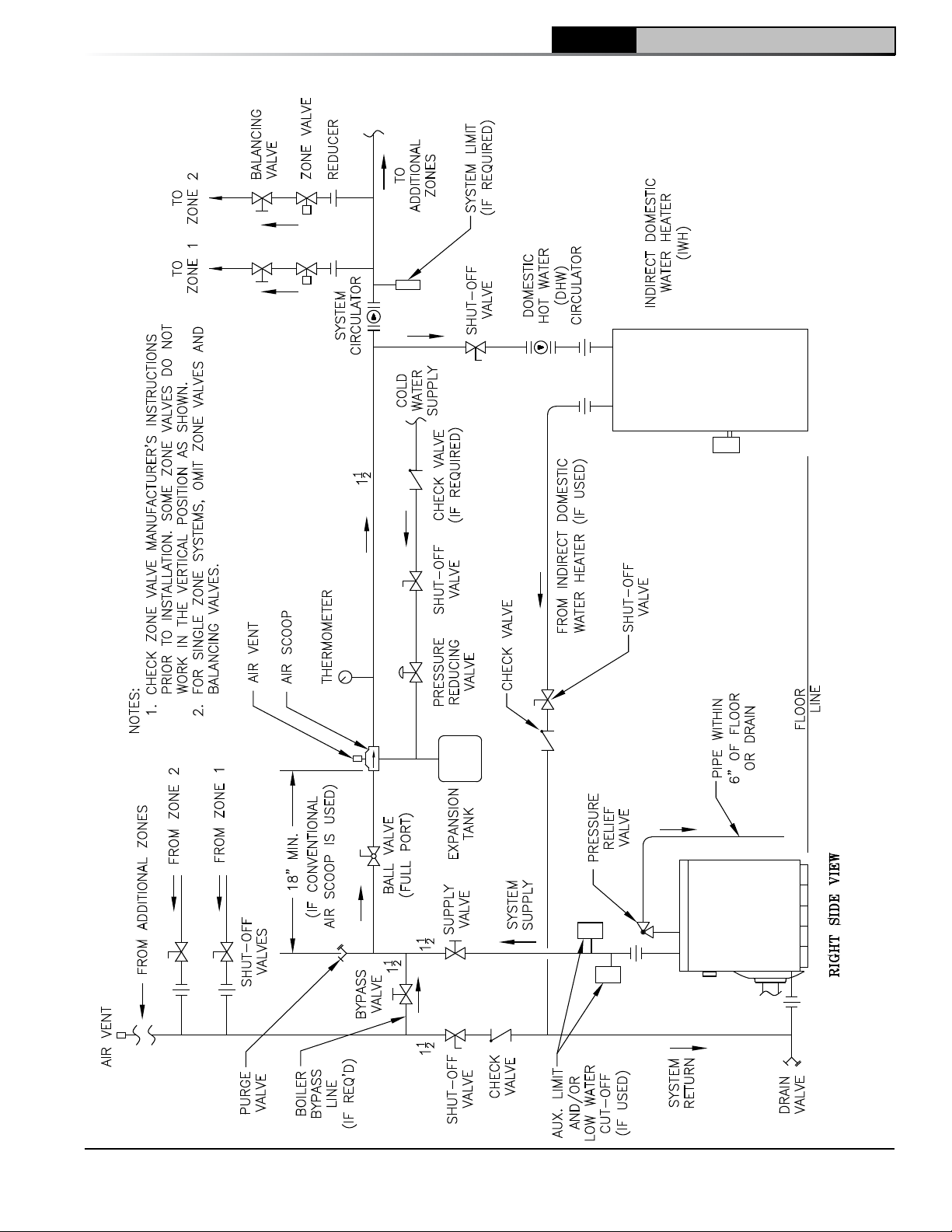
3 Installation Instructions (continued)
CL
Installation & Service Manual
103876-08 - 1/19
Figure 12B: Recommended Water Piping for Zone Valve Zoned Heating System - Supply Side Circulator
17
Page 18
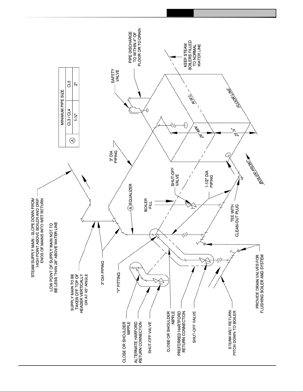
3 Installation Instructions (continued)
CL Installation & Service Manual
18
Figure 13: Recommended Boiler Piping for Gravity Return Steam Boiler
103876-08 - 1/19
Page 19
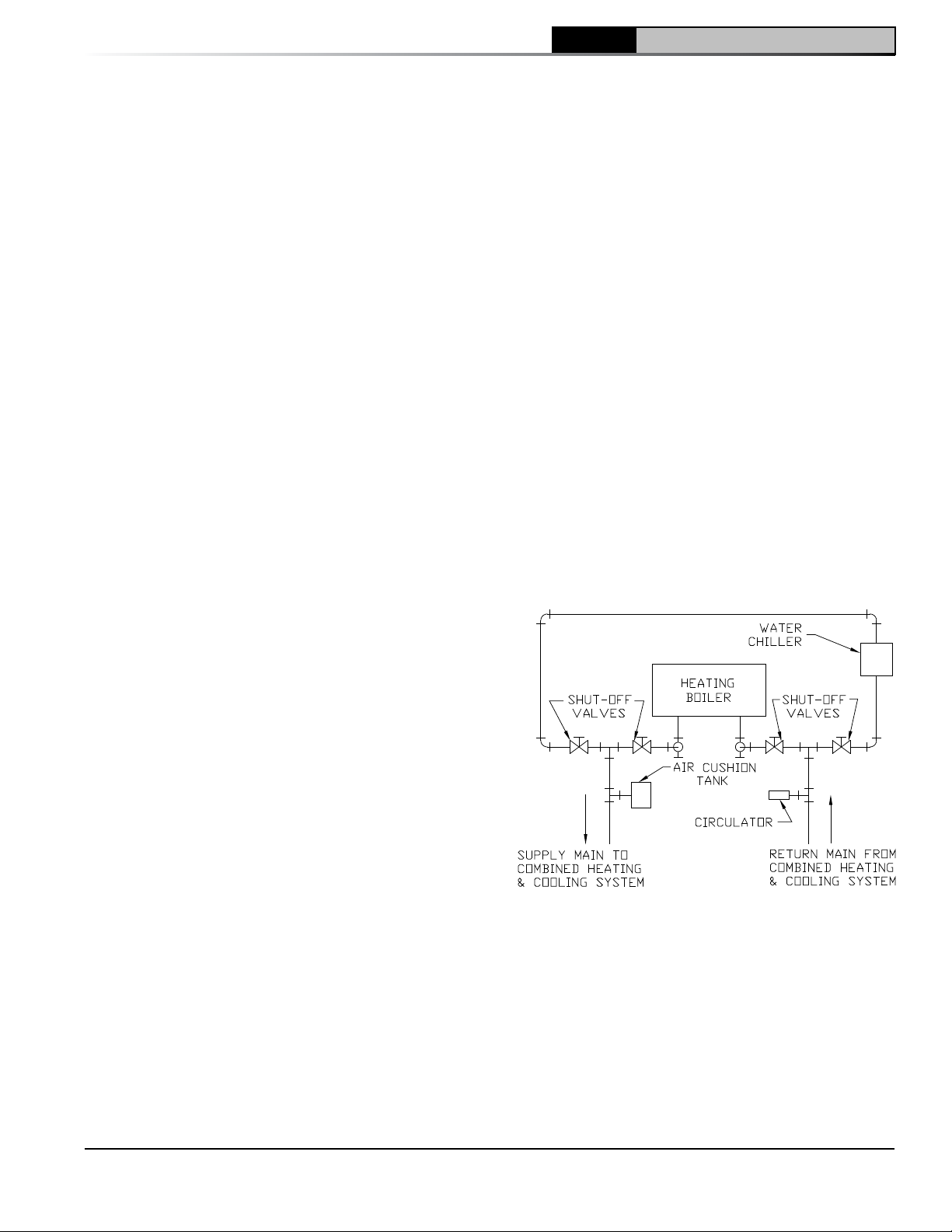
3 Installation Instructions (continued)
CL
Installation & Service Manual
Note:
• The GeniSys 7505 Oil Primary Control has
pre-installed "T-T" jumper. To activate "T-T"
terminals, "T-T" jumper must be removed.
• DO NOT remove "T-T" jumper unless wiring
diagram indicates a direct connection from
thermostat and/or tankless heater aquastat
control to the oil burner primary control's "TT" terminal. Refer to Figure 23.
I. CONNECT SUPPLY AND RETURN PIPING TO
HEATING SYSTEM.
1. Clearances — Steam and hot water pipes
shall have clearances of at least ½” from all
combustible construction.
2. Water Boiler
a. For Forced Circulation HOT WATER
HEATING. See Figures 12A and 12B.
Consult I=B=R, "Residential Hydronic
Heating Installation and Design Guide".
b. Use a boiler water bypass if the boiler
is to be operated in a system which has
a large volume or excessive radiation
where low boiler water temperature may
be encountered (i.e. converted gravity
circulation system, etc.).
Install a pipe tee in the boiler return piping
along with a second tee in the supply piping
as shown in Figures 12A and 12B. The
bypass should be the same size as the
supply and return lines. Locate valves in
the bypass and supply outlet as illustrated
in Figures 12A and 12B for regulation of
water flow to maintain higher boiler water
temperature.
Set the by-pass and boiler supply valves
to a half throttle position to start. Operate
boiler until the system water temperature is
a normal operating range.
Adjust the valves to provide 180° to 200°F
supply water temperature. Opening
the boiler supply valves will raise the
system temperature, while opening the
bypass valve will lower the system supply
temperature.
NOTICE Before using copper for steam piping, consider the following characteristics of copper piping:
1. High coefficient of thermal expansion can induce mechanical stresses and cause expansion/contraction
noises if not accounted for in the piping system design and installation,
2. High heat transfer rate (heat loss) of un-insulated copper piping must be included in the normal piping and
pickup factors used to size the boiler,
3. Soldering or brazing pastes and fluxes that end up in the system can cause poor heat transfer, surging, an
unsteady water line and wet steam if not thoroughly removed during boil out procedure and,
4. Galvanic corrosion of the adjoining metal may occur due to dissimilar metals in certain water chemistries if
dielectric unions are not used.
c. If this boiler is connected to heating coils
located in air handling units where they may
be exposed to refrigerated air the boiler
piping must be equipped with flow control
valves to prevent gravity circulation of boiler
water during the operation of the cooling
system.
d. If this boiler is used in connection with
refrigeration systems, the boiler must be
installed so that the chilled medium is piped
in parallel with the heating boiler using
appropriate valves to prevent the chilled
medium from entering the boiler, see Figure
14. Also, consult I=B=R, "Residential
Hydronic Heating Installation and Design
Guide".
e. A hot water boiler installed above radiation
level must be provided with a low water
cutoff device as part of the installation.
See Appendix A, Low Water Cut-Off for
additional details.
3. Steam Boiler
a. For Recommended STEAM BOILER PIPING
refer to Figure 13. Also, consult I=B=R,
"Residential Hydronic Heating Installation
and Design Guide".
Figure 14: Recommended Piping for Combination
Heating & Cooling (Refrigeration) Systems
103876-08 - 1/19
19
Page 20
3 Installation Instructions (continued)
b. Evaluate the Existing Steam System.
The single most important factor in
determining the expected life cycle of a
steam boiler, is the amount of fresh water
added to the boiler during operation. Fresh
water brings minerals and oxygen into
the boiler. These contaminants greatly
accelerate corrosion of the cast iron boiler
sections.
i. Assure that all system radiators, piping
and vents are absolutely leak tight.
• When a steam boiler is installed in an
existing system, ALL air vents should
be replaced at the same time. This
assures that the new boiler will not be
compromised by existing system
leaks.
• If the system contains hidden supply
or return piping (hidden behind walls,
buried in concrete, etc.) pressure
test this piping to assure there are no
leaks.
ii. Repair any leaks in the system.
iii. Install accurate water meter on the fresh
water supply to the boiler.
NOTICE DO NOT use softened water in steam
boilers. Accelerated boiler corrosion will
result. Tie in fresh water supply to the boiler
upstream of a water softener.
4. Oxygen Contamination:
a. There are many possible causes of oxygen
contamination such as:
i. Addition of excessive make-up water as
a result of system leaks.
ii. Absorption through open tanks and
fittings.
iii. Oxygen permeable materials in the
distribution system.
b. In order to insure long product life, oxygen
sources should be eliminated. This can
be accomplished by taking the following
measures:
i. Repairing system leaks to eliminate the
need for addition of make-up water.
ii. Eliminating open tanks from the system.
iii. Eliminating and/or repairing fittings
which allow oxygen absorption.
iv. Use of non-permeable materials in the
distribution system.
v. Isolating the boiler from the system
water by installing a heat exchanger.
See Section VII, Paragraph B, Step 3 for
additional details.
CL Installation & Service Manual
CAUTION
the boiler water will cause corrosion of iron
and steel boiler components, and can lead to
boiler failure. New Yorker's Standard Warranty
does not cover problems caused by oxygen
contamination of boiler water or scale (lime)
build-up caused by frequent addition of water.
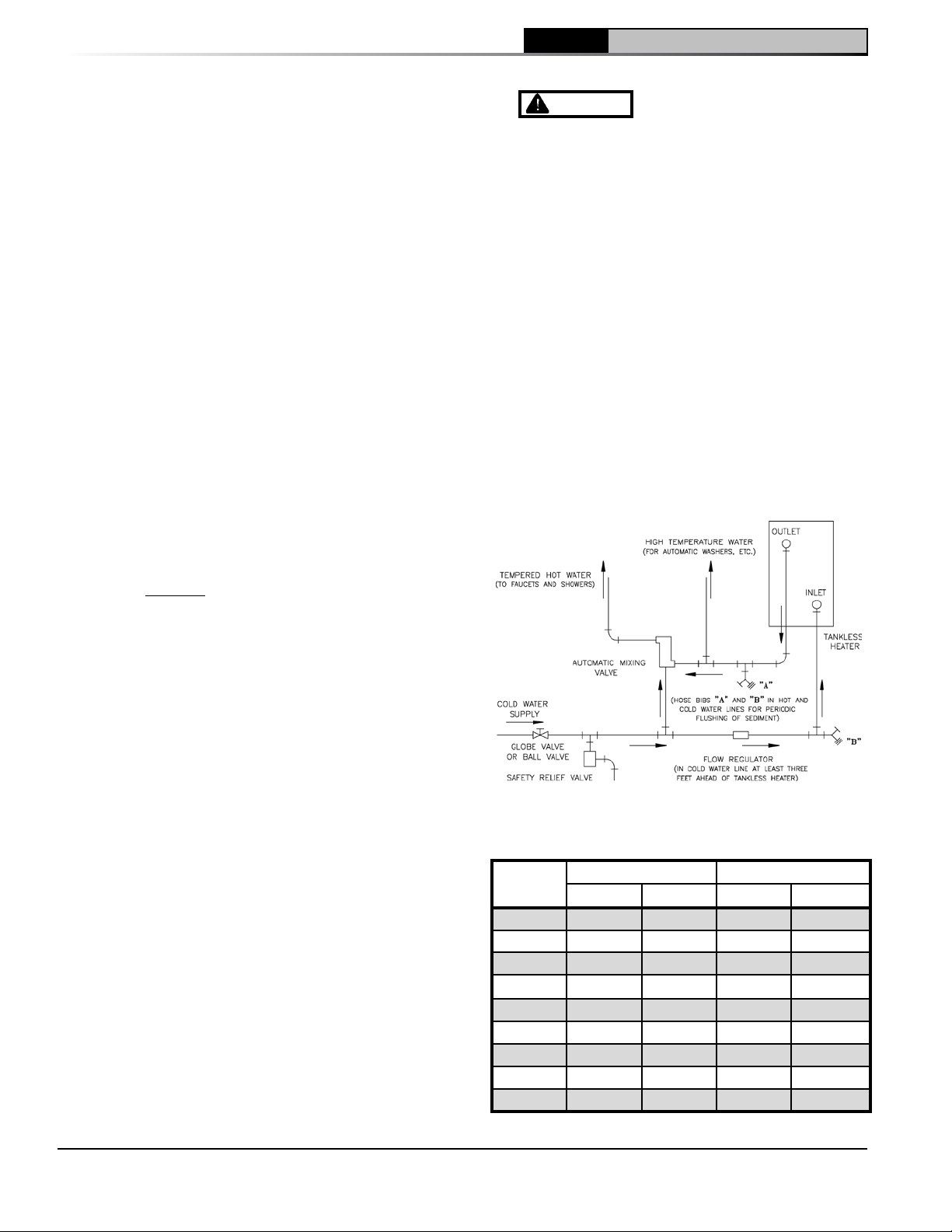
J. CONNECT TANKLESS HEATER PIPING AS
SHOWN IN Figure 15. See Table 4 for Tankless
Heater Ratings.
The following guidelines should be followed when
piping the tankless heater:
1. Flow Regulation — If flow through the heater is
greater than its rating, the supply of adequate
hot water may not be able to keep up with
the demand. For this reason a flow regulator
matching the heater rating should be installed
in the cold water line to the heater. The flow
regulator should preferably be located below
the inlet to the heater and a minimum of 3’
Figure 15: Schematic Tankless Heater Piping
Table 4: Tankless Heater Data
Boiler
Series
CL3-091 2.25 2.75 2.3 3.9
CL3-105 2.25 3.00 2.3 4.7
CL3-140 2.50 3.25 3.1 5.6
CL4-126 2.50 3.25 3.1 5.6
CL4-175 2.75 3.75 3.9 7.2
CL4-210 3.00 4.00 4.7 8.0
CL5-168 2.75 3.50 3.9 6.4
CL5-245 3.25 4.25 5.6 8.8
CL5-280 3.50 4.75 6.4 9.6
Rating (Gal/Min) Pressure Drop (PSI)
Steam Water Steam Water
Oxygen contamination of
20
103876-08 - 1/19
Page 21
CL
Installation & Service Manual
3 Installation Instructions (continued)
away from the inlet so that the regulator is not
subjected to excess temperatures that may
occur during “off” periods when it is possible
for heat to be conducted back through the
supply line. The flow regulator also limits
the flow of supply water regardless of inlet
pressure variations in the range of 20 to 125
psi.
2. Tempering Hot Water — Installation of an
automatic mixing valve will lengthen the
delivery of the available hot water by mixing
some cold water with the hot. This prevents
excessive and possibly scalding hot water
at the fixtures. In addition, savings of hot
water will be achieved since the user will not
waste as much hot water while seeking water
temperature to his liking. Higher temperature
hot water required by dishwashers and
automatic washers is possible by piping the
hot water from the heater prior to entering
the mixing valve. The mixing valve should be
“trapped” by installing it below the cold water
inlet to heater to prevent lime formation in the
valve.
WARNING
valve at tankless heater outlet to avoid risk of
burns or scalding due to excessively hot water
at fixtures. Adjust and maintain the mixing
valve in accordance with the manufacturer's
instructions.
3. Flushing of Heater — All water contains some
sediment which settles on the inside of the
coil. Consequently, the heater should be
periodically backwashed. This is accomplished
by installing hose bibs as illustrated and
allowing water at city pressure to run into
hose bib A, through the heater, and out hose
bib B until the discharge is clear. The tees in
which the hose bibs are located should be the
same size as heater connections to minimize
pressure drop.
4. Hard Water — A water analysis is necessary
to determine the hardness of your potable
water. This is applicable to some city water
and particularly to well water. An appropriate
water softener should be installed based on
the analysis and dealer’s recommendation.
This is not only beneficial to the tankless heater
but to piping and fixtures plus the many other
benefits derived from soft water.
K. Indirect Water Heater Piping
1. Connect Indirect Water Heater Piping as
shown in Figures 12A and 12B for water boilers
and Figures 13 and 16 for steam boilers. Refer
103876-08 - 1/19
Install automatic mixing
to Indirect Water Heater Instruction Manual for
additional installation information.
a. CL Series Water Boiler - Figures 12A and
12B show indirect water heater piping on
typical hot water heating system. Boiler
piping is the same as for any two-zone
system. Figures 12A and 12B show
circulator zoning, which is usually preferred
for indirect water heaters. Size the
circulator and indirect water heater piping
to obtain the boiler water flow through
the indirect water heater called for by the
indirect water heater manufacturer. Refer to
the indirect water heater instruction manual
for additional details.
b. CL Series Steam Boiler - All CL Series
steam boilers are equipped with tappings
to permit the connect of an indirect water
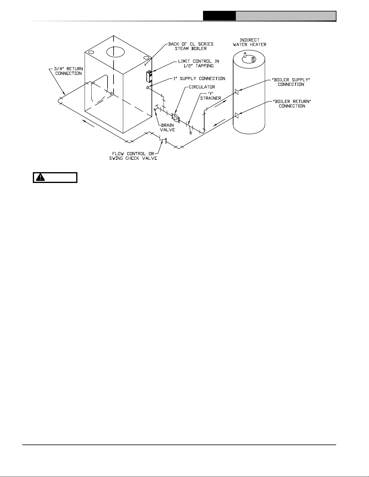
heater, see Figures 2B and 16. In this type
of system, hot boiler water is drawn from
below the water line and passed through
the heat exchanger in the indirect water
heater.
This section describes boiler-side piping
only. Refer to the indirect water heater
instruction manual for additional details.
L. Chimney Venting
1. Chimney venting is an important part of a
safe and efficient oil fired appliance system.
Contact your local fire and building officials
on specific requirements for restrictions and
the installation of fuel oil burning equipment.
In addition, consult with a professional
knowledgeable on the requirements of NFPA
31 – Standard for the Installation of Oil-Burning
Equipment and NFPA 211 - Standard for
Chimneys, Fireplaces, Vents, and Solid FuelBurning Appliances for installations in the
United States. Installations in Canada must be
reviewed with a professional knowledgeable
on the requirements of CSA B139 – Installation
Code for Oil-burning Equipment.
2. The safe venting of oil fired boilers is
dependant on many factors. Some of these
factors include:
a. sufficient draft during the entire heating
season to allow for the safe discharge of
combustion by-products and;
b. suitable corrosion protection in the event of
condensing flue gases. Only a trained and
qualified contractor may install this product.
3. The CL shall be vented into any of the
following:
a. Masonry or metal chimney. Build and install
in accordance with local buildings codes;
21
Page 22
CL Installation & Service Manual
3 Installation Instructions (continued)
Figure 16: Indirect Water Heater Piping on CL Series Steam Boiler
WARNING
combustion to enter the home resulting in severe property damage, personal injury or death.
Insufficient Combustion Air Supply may result in the production and release of deadly carbon monoxide
(CO) into the home which can cause severe personal injury or death.
Improper venting may result in property damage and the release of flue gases which contain deadly
carbon monoxide (CO) into the home, which can cause severe personal injury, death, or substantial
property damage.
Inspect existing chimney and vent connector for obstructions and deterioration before installing boiler.
Failure to clean or replace perforated pipe or chimney liner will cause severe injury or death.
Do not de-rate the appliance. Failure to fire the boiler at it's designed input may cause excessive
condensation upon the interior walls of the chimney. In addition, the lower input may not create enough
draft to adequately evacuate the by-products of combustion.
or local authority having jurisdiction; or
“Standards for Chimney, Fireplace, Vents,
and Solid Fuel Burning Appliances”, ANSI/
NFPA 211 and/or National Building Code of
Canada. Masonry chimney must be lined
with listed chimney system. Listed clay
flue lined masonry chimneys meet venting
requirements.
• External chimneys are more susceptible
• Oversized chimneys are more
4. Chimney Inspection – Prior to the installation
of any new or replacement fuel burning
Vent this boiler according to these instructions. Failure to do so may cause products of
equipment the chimney shall be inspected
by a qualified installer. The chimney shall
be inspected for integrity as well as for
proper draft and condensate control. Some
jurisdictions require the use of a liner when
changing fuel types. Some jurisdictions
require the use of a liner even when the same
fuel is used. At a minimum, the chimney
shall be examined by a qualified person in
to flue gas condensation due to colder
outside air temperatures. To prevent
corrosion due to flue gas condensation,
use a listed corrosion-resistant metal
liner in chimney.
susceptible to flue gas condensation.
To reduce the likelihood of flue gas
condensation and ensure proper draft,
use a properly sized listed metal liner in
oversized chimney.
accordance with the requirements of Chapter
11 of NFPA 211, Standard for Chimneys,
Fireplaces, Vents, and Solid Fuel-Burning
Appliances.
a. Loose Mortar – Loose mortar could be an
indication of a prior history of condensing
flue gases upon the inside walls of the
chimney. Colder climates are more
susceptible to this condition. Under
no circumstances shall a chimney of
this condition be used until it meets the
requirements of NFPA 211 or CSA B139.
b. Unlined Chimney – Under no circumstances
shall a chimney constructed of brick only be
22
103876-08 - 1/19
Page 23
3 Installation Instructions (continued)
used. Only approved clay liners or listed
chimney lining systems shall be used as
specified in NFPA 31 or CSA B139.
c. Abandoned Openings – Openings through
the chimney wall that are no longer used
shall be sealed in accordance to NFPA 211.
Often abandoned openings are improperly
sealed and usually covered by a gypsum
wall covering.
d. Clean Chimney – Chimney shall be free of
all loose debris.
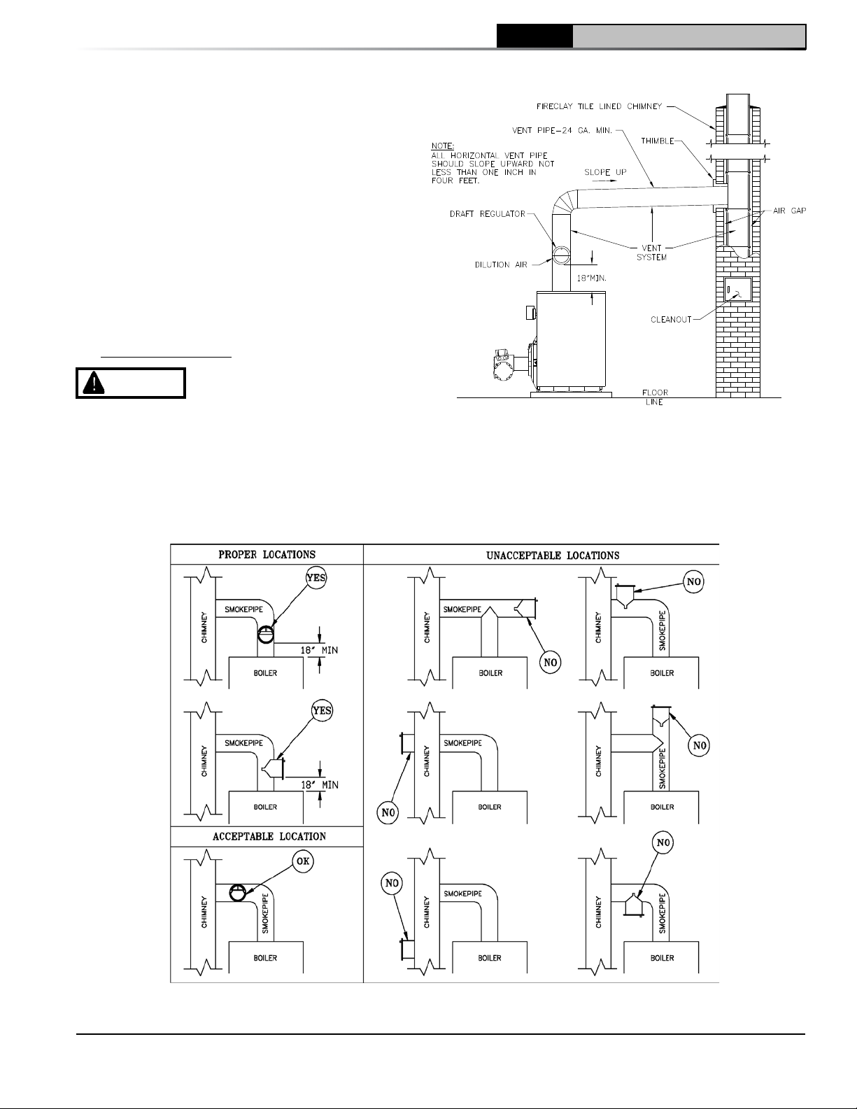
5. Draft Regulator – a draft regulator must be
used with this appliance. Refer to Figures 17
and 18.
Chimney Connector
CL
Installation & Service Manual
DANGER
be inspected annually for signs of debris and
corrosion. Loose mortar at the base of the
chimney may be a sign of condensate damage
to the chimney. A chimney professional shall
be contacted immediately to examine the
damage and recommend a solution. Long
The chimney and connector shall
Figure 17: Recommended Smokepipe Arrangement
and Chimney Requirements
103876-08 - 1/19
Figure 18: Proper and Improper Locations of Draft Regulator
23
Page 24
CL Installation & Service Manual
3 Installation Instructions (continued)
term operation while in this condition may
cause a venting failure and force flue gases
into the living space. If the chimney is to be
re-lined use the recommendations in NFPA 31,
Appendix E or CSA B139.
1. A chimney connector (vent pipe) is used to
connect the boiler to the base of the chimney.
The chimney connector should be kept as
short as possible. The horizontal length of the
chimney connector shall not be greater than 10
feet.
2. Vent Connector shall be any of the following
and of the same size as the outlet of boiler.
a. Type L or a factory built chimney material
that complies with the Type HT requirements
of ANSI/UL 103. Install in accordance with
listing and manufacturer’s instructions.
b. Steel pipe having resistance to corrosion
and heat with a minimum wall thickness of
24 Gauge (0.024”).
Draft
DANGER
seepage at the base of the chimney shall be
inspected immediately. The discoloration may
be a sign of chimney damage and must be
remedied immediately.
1. The natural draft generated through a chimney
is dependent on several factors including,
chimney height, temperature of flue gases,
cross section area of chimney, chimney wall
insulation value, dilution air and total volume of
flue gases, to name a few. Make sure that the
boiler has been running for at least 5 minutes
before measuring the draft.
2. Minimum Draft Overfire – The draft induced
by a chimney must create at least a pressure
of -0.02 inches water column ("w.c.). The
pressure at the canopy cannot be positive
since this could create a condition that allows
flue gas by-products to escape from the draft
regulator. A negative pressure reading up to
-.03 inches water column is acceptable for
proper operation.
Stack Temperature
1. The temperature of the flue gases has a
significant effect on the amount of draft
created in a vertical chimney as well as the
propensity to create condensate. The higher
the stack temperature, the greater the amount
of draft that can be generated. A lower stack
temperature not only reduces the amount of
draft that can be created but it also increases
Any signs of condensate
the possibility that the flue gases could
condense in the chimney connector or stack.
2. NFPA 31 and CSA B139 have information to
help the installer make an appropriate choice
of venting materials. In some cases a chimney
may have to be lined to create sufficient draft.
In other cases, the chimney may have to be
lined to prevent the corrosion of a masonry
chimney. Consult with a chimney specialist
knowledgeable on the requirements for
chimney requirements in your area.
CAUTION
of a chimney or it’s ability to prevent the
generation and accumulation of flue gas
condensate, must be relined according to
NFPA 31 (United States) or CSA B139 (Canada).
• Use the chimney venting tables as a guide. It
is highly recommended that any borderline
application should result in the relining of
the chimney with a suitable liner that creates
sufficient draft and to protect against corrosion
caused by flue gas condensate.
Any doubt on the condition
IMPORTANT
Single-pipe installations must be absolutely
airtight or leaks or loss of prime may result. Bleed
line and fuel unit completely.
M. FUEL UNITS AND OIL LINES
Single-Pipe Oil Lines - Standard burners are
provided with single-stage 3450 rpm fuel units
with the by-pass plug removed for single-pipe
installations..
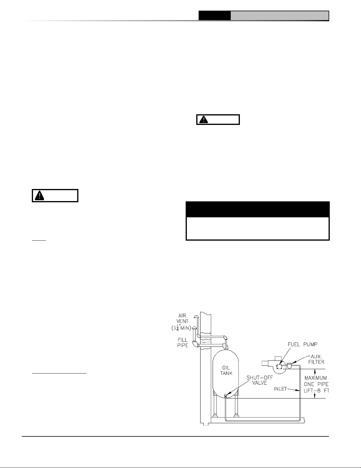
The single-stage fuel unit may be installed single-
pipe with gravity feed or lift. Maximum allowable
lift is 8 feet. See Figure 19.
Figure 19: Single Pipe Oil Line
24
103876-08 - 1/19
Page 25
3 Installation Instructions (continued)
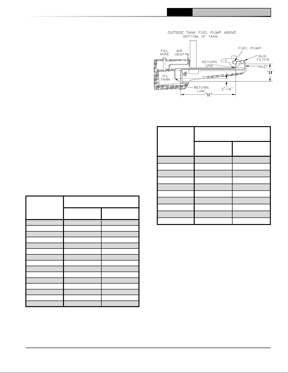
Two-Pipe Oil Lines - For two-pipe systems where
more lift is required, the two-stage fuel unit is
recommended. Table 5 (single-stage) and Table
6 (two-stage) show allowable lift and lengths of
3/8-inch and 1/2-inch OD tubing for both suction
and return lines. Refer to Figure 20.
Be sure that all oil line connections are absolutely
airtight. Check all connections and joints.
Flared fittings are recommended. Do not use
compression fittings.
Open the air-bleed valve and start the burner. For
clean bleed, slip a 3/16" ID hose over the end
of the bleed valve and bleed into a container.
Continue to bleed for 15 seconds after oil is free
of air bubbles. Stop burner and close valve.
Table 5: Single Stage Units (3450 rpm)
Two Pipe Systems
Maximum Length of Tubing
Lift "H"
(See Figure)
0' 84' 100'
1' 78' 100'
2' 73' 100'
3' 68' 100'
4' 63' 100'
5' 57' 100'
6' 52' 100'
7' 47' 100'
8' 42' 100'
9' 36' 100'
10' 31' 100'
11' 26' 100'
12' 21' 83'
13' --- 62'
14' --- 41'
"H" + "R" (See Figure)
3/8" OD
Tubing (3 GPH)
1/2" OD
Tubing (3 GPH)
CL
Installation & Service Manual
Figure 20: Two Pipe Oil Lines
Table 6: Two-Stage Units (3450 rpm)
Two-Pipe Systems
Maximum Length of Tubing
Lift "H"
(See Figure)
"H" + "R" (See Figure)
3/8" OD
Tubing (3 GPH)
0' 93' 100'
2' 85' 100'
4' 77' 100'
6' 69' 100'
8' 60' 100'
10' 52' 100'
12' 44' 100'
14' 36' 100'
16' 27' 100'
18' --- 76'
1/2" OD
Tubing (3 GPH)
103876-08 - 1/19
25
Page 26
CL Installation & Service Manual
4 Electrical
• Electrical power may be from more than one source. Make sure all power is off before attempting any
• Each boiler must be protected with a properly sized fused disconnect.
• Never jump out or make inoperative any safety or operating controls.
• The primary control may be damaged or may not function properly if 120 volt power supply is NOT wired
The 120V interrupted hot (black) wire must be connected to the primary control black wire, the 120V
DANGER
or service of electrical components or connections of the boiler or building. Lock out all electrical boxes
with padlock once power is turned off.
WARNING
harm.
electrical work.
into control as follows:
neutral (white) wire must be connected to the primary control white wire and the 120V constant hot (red)
wire must be connected to the primary control red wire.
Positively assure all electrical connections are unpowered before attempting installation
Failure to properly wire electrical connections to the boiler may result in serious physical
A. General
1. Install wiring and electrically ground boiler in
accordance with requirements of the authority
having jurisdiction, or in absence of such
requirements the National Electrical Code,
ANSI/NFPA 70.
2. Refer to National Electric Code or Local
Electric Codes for proper size and type of wire
required. Follow Code.
3. A separate electrical circuit must be run from
the main electrical service with an over-current
device/disconnect in the circuit. A service
switch is recommended and may be required
by some local jurisdictions.
4. Use anti-short bushings on all wiring passing
through boiler jacket, junction boxes and/or
control boxes.
5. Use armored cable (BX) over all exposed line
voltage wiring.
6. If an indirect domestic water heater is used,
use priority zoning. DO NOT use priority
zoning for Hydro-Air Systems.
7. Wiring should conform to Figures 21 through
25.
B. Install A room thermostat on an inside wall about
four feet above floor. Never install thermostat on
an outside wall or where it will be influenced by
drafts, hot or cold water pipes, lighting fixtures,
television, rays of the sun or near a fireplace.
Keep large furniture away from thermostat so
there will be free movement of room air around
this control.
Heat Anticipator in Thermostat should be set to
match the requirements of the control to which
it is connected. See Figures 21 through 25 for
desired system and heat anticipator setting. If
system tends to overheat above the thermostat's
temperature setting, reduce heat anticipator
setting by .1 or .2 amps. If system tends to short
cycle without reaching desired room temperature,
increase heat anticipator setting by .1 or .2 amps.
26
103876-08 - 1/19
Page 27
4 Electrical (continued)
CL
Installation & Service Manual
REFER TO FIGURE 25 FOR
SCHEMATIC WIRING DIAGRAM OF
APPROPRIATE BURNER AND OIL
PRIMARY CONTROL OPTION
103876-08 - 1/19
Figure 21: Schematic Wiring Diagram, without Tankless Heater, Cold Start Control (All Burners)
27
Page 28
4 Electrical (continued)
CL Installation & Service Manual
REFER TO FIGURE 25 FOR
SCHEMATIC WIRING DIAGRAM
OF APPROPRIATE BURNER
AND OIL PRIMARY CONTROL
OPTION
28
Figure 22: Schematic Wiring Diagram, with Tankless Heater, Warm Start Control (All Burners)
103876-08 - 1/19
Page 29

4 Electrical (continued)
CL
Installation & Service Manual
Lettered
Terminals
Terminals
Numbered
Numbered as Follows:
McDonnell & Miller PSE-801
Terminals May Be Lettered or
Wire
Color
BK 1 H
RD 5 B
WH 2 N
Jumper 1-3 H-C
REFER TO FIGURE 25 FOR
SCHEMATIC WIRING DIAGRAM OF
APPROPRIATE BURNER AND OIL
PRIMARY CONTROL OPTION
McDonnell & Miller PSE-801 Probe LWCO, Beckett AFG and Carlin EZ Burners
Figure 23: Schematic Wiring Diagram, Steam Boilers With or Without Tankless Heater,
103876-08 - 1/19
29
Page 30
4 Electrical (continued)
CL Installation & Service Manual
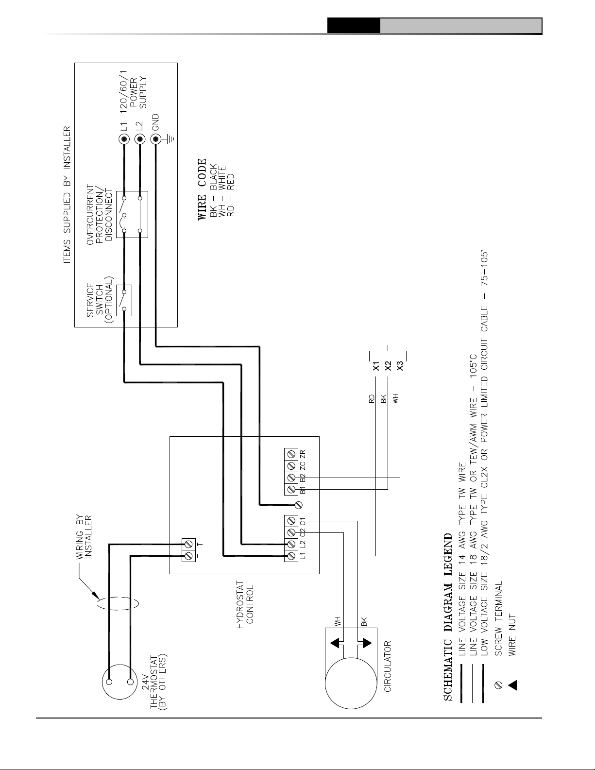
REFER TO FIGURE 25 FOR
SCHEMATIC WIRING DIAGRAM
OF APPROPRIATE BURNER
AND OIL PRIMARY CONTROL
OPTION
Hydrolevel HydroStat, All Burners
Figure 24: Schematic Wiring Diagram, Water Boilers with or without Tankless Heater,
30
103876-08 - 1/19
Page 31
4 Electrical (continued)
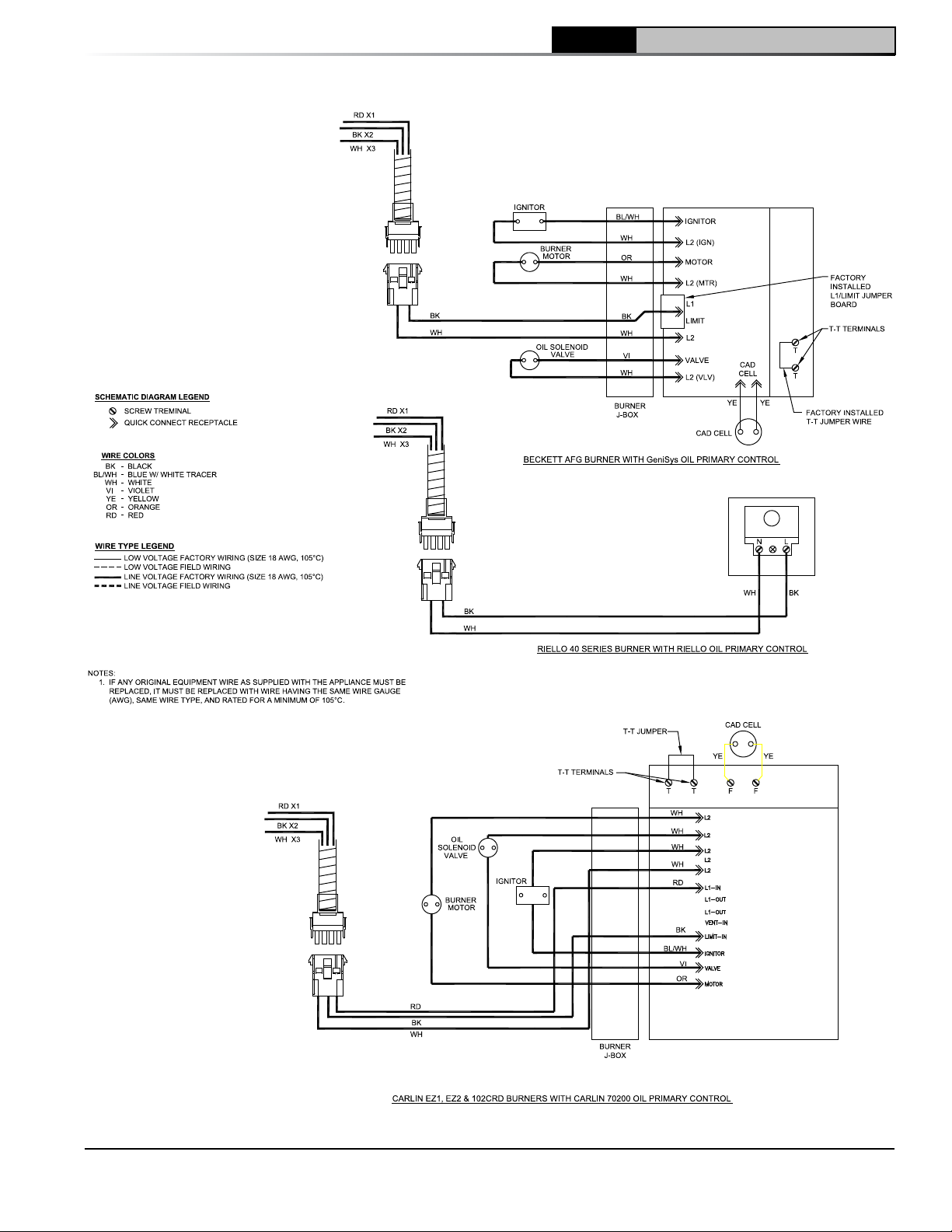
NOTE: APPLY THIS BURNER
SCHEMATIC TO APPROPRIATE
STEAM OR WATER BOILER
CONTROL SCHEMATIC, REFER
TO FIGURES 21 THRU 24
NOTE: APPLY THIS
BURNER SCHEMATIC TO
APPROPRIATE STEAM OR
WATER BOILER CONTROL
SCHEMATIC, REFER TO
FIGURES 21, 22 AND 24
CL
Installation & Service Manual
NOTE: APPLY THIS BURNER
SCHEMATIC TO APPROPRIATE
STEAM OR WATER BOILER
CONTROL SCHEMATIC, REFER
TO Figures 21 THRU 24
Figure 25: Schematic Wiring Diagrams For All Burner Options w/Various Oil Primary Controls
103876-08 - 1/19
31
Page 32
5 System Start-Up
CL Installation & Service Manual
WARNING
severe property damage, personal injury or loss of life if ignored. Before opening swing door, turn off
service switch to boiler to prevent accidental firing of burner outside the combustion chamber. Be sure to
tighten swing door fastener completely when service is completed.
A. ALWAYS INSPECT INSTALLATION BEFORE
STARTING BURNER.
1. Verify that the venting, water piping, oil piping,
and electrical system are installed properly.
Refer to Installation Instructions contained in
this manual.
2. Confirm all electrical, water and oil supplies
are turned off at the source and that the vent is
clear from obstructions.
WARNING
and follow all instructions in this manual
before attempting start up.
B. FILL HEATING SYSTEM WITH WATER.
NOTICE It is important, especially in a steam
system, to properly remove the oil and dirt from
the system. Failure to clean the system can
result in erratic water lines and surging.
Clean Heating System if boiler water or
condensate return water is dirty or if erratic water
lines or surging exist after a few days of boiler
operation.
Refer to Maintenance and Service Instructions
Section of this manual for proper cleaning
instructions for steam and water boilers.
1. Steam Boilers — Fill boiler to normal water line.
Refer to Figure 1C.
2. Hot Water Boilers. Fill entire heating system
with water and vent air from system. Use the
following procedure on a series loop or multizoned system installed as per Figures 12A and
12B, to remove air from system when filling:
a. Close full port ball valve in boiler system
piping.
b. Isolate all zones by closing zone valves or
shut-off valves in supply and return of each
zone(s).
c. Attach a hose to vertical purge valve in
boiler system piping.
(Note - Terminate hose in five gallon bucket at
a suitable floor drain or outdoor area).
d. Starting with one zone at a time, open zone
valve or shut-off valve in boiler supply and
return piping.
All boilers equipped with burner swing door have a potential hazard which can cause
e. Open purge valve.
f. Open shut-off valve in cold water supply
piping located between the air scoop and
expansion tank.
g. Allow water to overflow from bucket until
discharge from hose is bubble free for 30
seconds.
h. When zone is completely purged of air,
close zone valve or shut-off valve. Open
zone valve to the next zone to be purged.
Completely read, understand
NOTICE If make-up water line is equipped
C. CHECK CONTROLS, WIRING AND BURNER to
D. ADJUST CONTROL SETTINGS with burner
Repeat this step until all zones have been
purged. At completion, open all zone
valves.
i. Close purge valve, continue filling the
system until the pressure gauge reads
12 psi. Close shut-off valve in cold water
supply piping.
WARNING
pressure of this boiler is posted on the ASME
Data Label located on the top of the boiler.
Never exceed this pressure. DO NOT plug
safety or relief valve.
with pressure reducing valve, system will
automatically fill to 12 psi. Follow fill valve
manufacturer's instructions.
j. Open full port ball valve in boiler system
piping.
k. Remove hose from purge valve.
l. Confirm that the boiler and system have no
water leaks.
be sure that all connections are tight and burner
is rigid, that all electrical connections have been
completed and fuses installed, and that oil tank is
filled and oil lines have been tested.
service switch turned “ON”.
1. Set Room Thermostat about 10°F below room
temperature.
2. Press Red Reset Button on front of burner
cover (Beckett, Riello burners) or Oil Primary
Control with burner cover removed. Hold
button for one (1) second and release to reset
primary control.
The maximum operating
32
103876-08 - 1/19
Page 33
5 System Start-Up (continued)
3. Steam Boilers:
With an PA404A Pressure Limit - set cut-out
pressure (MAIN scale) on the pressure limit
for (1) PSI and differential pressure (DIFF.) for
.5 PSI. These pressures may be varied to suit
individual requirements of the system.
4. Steam Boilers with Tankless Domestic Water
Heaters, set boiler water temperature dial on
L4006 operating control at 190°F (max.). Set
differential at 10°.
5. Water Boilers without Tankless Heaters, are
equipped with an Intelligent Oil Boiler Control
(Boiler Control). The Boiler Control is factory
programmed with a High Limit setpoint of
180°F. The High Limit setpoint is adjustable
between 140°F and 240°F. This temperature
may be varied to suit the installation
requirements.
High Limit Differential is factory programmed at
15°F and is adjustable between 10°F and 30°F.
6. Water Boilers with Tankless Heaters are
equipped with a Warm Start Intelligent Oil
Boiler Control (Warm Start Boiler Control).
The Warm Start Boiler Control is factory
programmed with a High Limit setpoint of
180°F. The High Limit setpoint is adjustable
between 140°F and 240°F. High Limit
Differential is factory programmed at 10°F.
Additionally, the Warm Start Boiler Control
is factory programmed with a Low Limit
setpoint of 110°F. The Low Limit setpoint is
adjustable between 110°F and 220°F. These
temperatures may be varied to suit the
installation requirements.
7. Checkout
Put the system into operation and observe
at least one complete cycle to make sure
that the controller operates properly. See
Troubleshooting Section to use LED to assist in
determining system operation.
E. ADJUST OIL BURNER BEFORE STARTING.
Check Burner Settings and readjust if necessary,
see Burner Specifications, Tables 14A and 14B
at rear of this manual.
1. Beckett Burners
a. Inspect Beckett head setting on left side
of burner housing by insuring the blue line
MD(V1) or the line on the label MB(L1) are
aligned, readjust if necessary. Refer to
Figure 27 and Table 14A at the rear of this
manual.
b. Check burner air band and air shutter
settings. Readjust if necessary, see Burner
103876-08 - 1/19
CL
Specifications Table 14A at the rear of this
manual.
c. Open all oil line valves.
d. Attach a plastic hose to fuel pump vent
fitting and provide a pan to catch the oil.
e. Open Flame Observation Port cover on
burner swing door.
2. Riello Burners
a. Inspect Riello head setting on left side of
burner by reading the scale embossed on
the housing cover. Refer to Figure 8.
b. Inspect Riello burner air damper and
turbulator setting. Readjust if necessary,
see Table 14B at the rear of this manual.
c. OPEN ALL OIL LINE VALVES.
d. Provide a pan to catch oil.
e. Remove pressure port/bleeder plug from
fuel pump and install Riello Combination
Pressure Gauge and Bleeder Valve
Assembly.
f. OPEN FLAME OBSERVATION PORT COVER
on burner swing door.
CAUTION
input and must be readjusted prior to starting
burner, if nozzle was changed to a lower firing
rate.
3. Carlin Burners
a. Inspect Carlin head setting on left side
of burner to ensure that the proper head
positioning bar matches the nozzle that is
installed in drawer assembly. Replace bar if
necessary.
b. Change the factory air settings according to
Table 14C (at rear of this manual)
c. Open all oil line valves.
d. Attach a plastic hose to fuel pump vent
fitting and provide a pan to catch the oil.
e. Open flame observation port cover on
burner swing door.
F. START OIL BURNER.
1. Open vent fitting on fuel pump.
2. Turn 'ON' Burner service switch and allow
burner to run until oil flows from vent fitting
in a solid stream without air bubbles for
approximately 10 seconds.
3. Close vent fitting and burner flame should
start immediately after prepurge is completed.
Prepurge prevents burner flame until 10
seconds has elapsed after initial power is
applied to burner. During prepurge the motor
Installation & Service Manual
Air Band is set for maximum
33
Page 34
CL Installation & Service Manual
5 System Start-Up (continued)
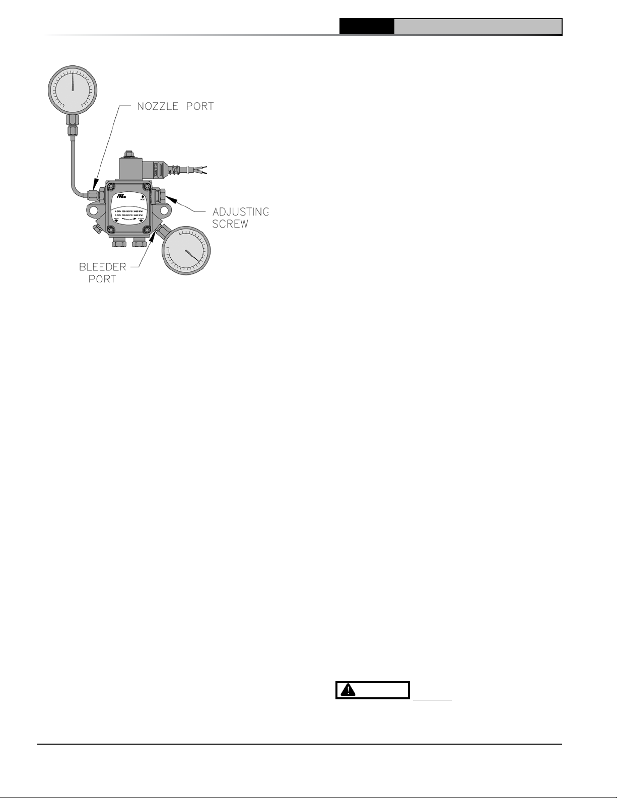
Figure 26: Adjusting Fuel Pump Pressure
and igniter will operate but the oil valve will
remain closed. Refer to Oil Primary Control
Instructions for more details.
4. Adjust oil pressure.
a. When checking a fuel unit's operating
pressure, a reliable pressure gauge may
be installed in either the bleeder port or the
nozzle port. Refer to Figure 26. Refer to
Figure 9 for Riello burner.
b. Locate oil pressure adjusting screw and
turn screw to obtain proper pump pressure,
refer to Tables 14A and 14B at the rear of
this manual.
c. To check the cutoff pressure, deadhead a
reliable pressure gauge onto the copper
connector tube attached to the nozzle port.
Run the burner for a short period of time.
Shut the burner off. The pressure should
drop and hold.
d. Remove the gauge and install bleeder port
and/or reconnect the nozzle port line.
G. ADJUST OIL BURNER WHILE OPERATING.(flame
present)
1. Set room thermostat about 10°F below room
temperature.
2. Press red reset button on Oil Primary Control
and release.
3. Beckett Burners - Readjust the head setting,
only if necessary.
a. CL3-091 thru CL4-126:
Beckett MB(L1) Head burners have a fixed
head which are non-adjustable.
b. CL4-175 thru CL5-280:
Beckett MD(V1) (variable) Head burners
have the ability to control air by moving the
head. It might be necessary to move the
head forward or back one position at a time
to optimize the smoke and CO2 readings.
See Figure 27 and Table 14A at the rear of
this manual.
4. Riello Burners - Readjust the turbulator setting,
only if necessary.
a. CL3 through CL5 (All Models)
Move the turbulator setting forward or back
one position at a time to optimize the smoke
and CO2 readings. Refer to Figure 8 and
Table 14B at the rear of this manual.
5. Readjust the Head Setting, only if necessary.
a. Carlin EZ-1HP and EZ-2HP burners use a
head positioning bar to fix the head setting
based on nozzle size. To adjust this setting,
bar must be changed to the next larger or
smaller bar available.
6. Readjust the Air Damper Setting (air Band/
Air Shutter/Air Gate) on the burner for a light
orange colored flame while the draft over the
fire is -0.02”. Use a smoke tester and adjust
air for minimum smoke (not to exceed #1) with
a minimum of excess air. Make final check
using suitable instrumentation to obtain a CO2
of 11.5 to 12.5% with draft of -0.02” (water
gauge) in fire box. These settings will assure
a safe and efficient operating condition. If the
flame appears stringy instead of a solid fire, try
another nozzle of the same type. Flame should
be solid and compact. After all adjustments
are made, recheck for a draft of -0.02” over the
fire.
7. Only Readjust the Head/Turbulator Setting, if
necessary.
a. CL3 through CL5 (All Models)
Move the setting forward or back one
position at a time to optimize the smoke and
CO2 readings.
b. Steps outlined in Paragraph 5 and 6
above must be repeated every time the
Head/Turbulator or Air Damper Setting is
readjusted.
8. Turn “OFF” burner and remove Riello
Combination Pressure Gauge and Bleeder
Valve Assembly. Install pressure port/bleeder
plug and tighten. Start burner again.
WARNING
oil line fittings while burner is operating.
DO NOT loosen or remove any
34
103876-08 - 1/19
Page 35
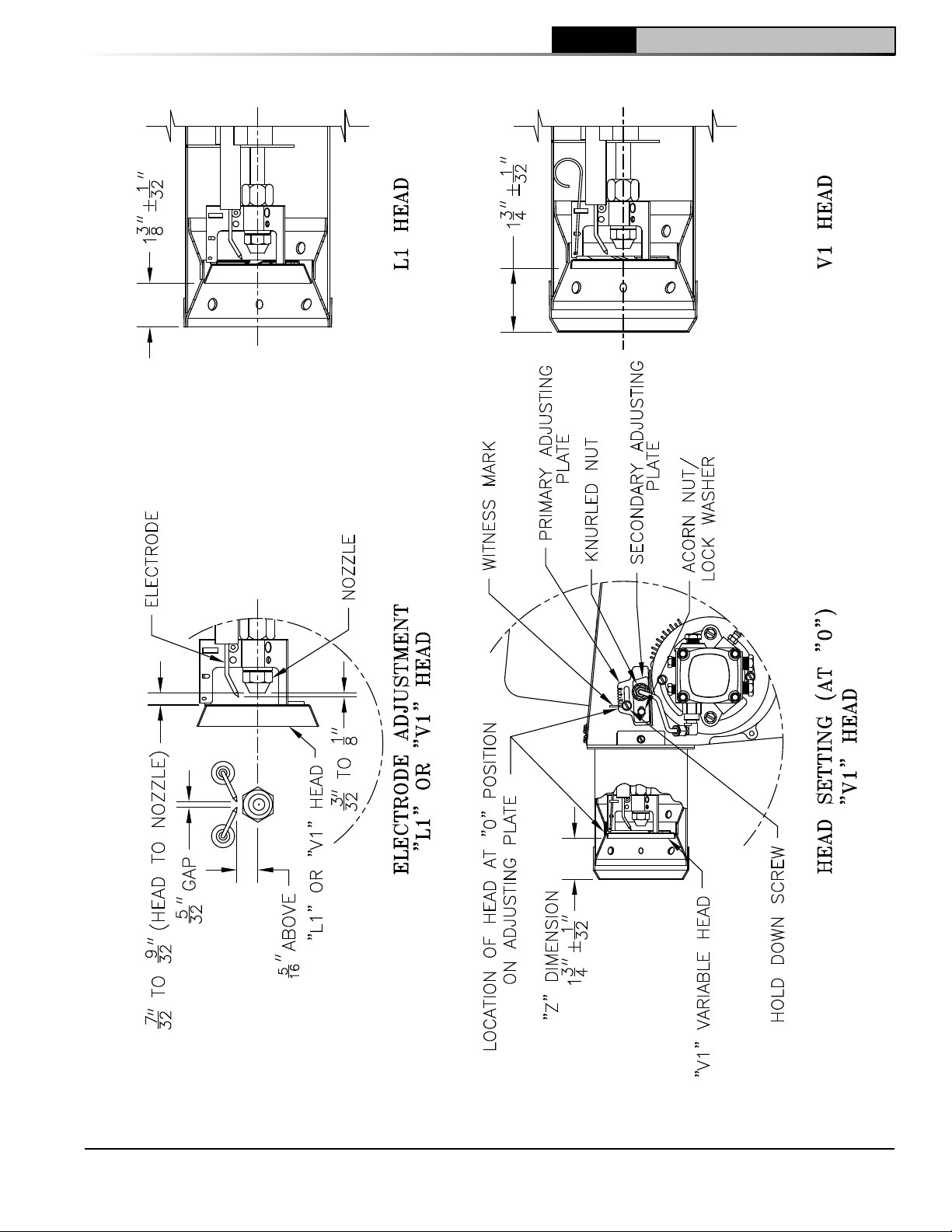
5 System Start-Up (continued)
CL
Installation & Service Manual
103876-08 - 1/19
Figure 27: "L1" and "V1" Head Electrode Positioning and Gun Setting (Beckett AFG)
35
Page 36
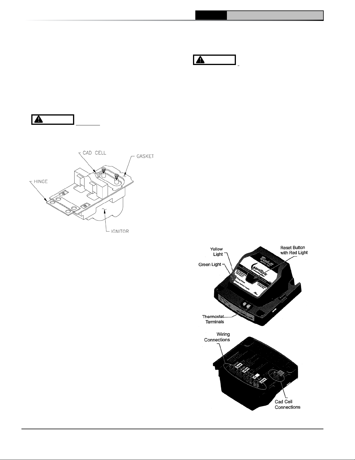
CL Installation & Service Manual
5 System Start-Up (continued)
9. Flame Failure
The CL boiler controls operate the burner
automatically. If for unknown reasons the
burner ceases to fire and the reset button on
the primary control has tripped, the burner
has experienced ignition failure. Refer to Oil
Primary Control features, Paragraph I, Step 2
of this Section and Section IX, Troubleshooting,
Paragraph B. If the failure re-occurs, call your
heating contractor immediately before pressing
the reset button.
WARNING
burner when excess oil has accumulated,
when the boiler is full of vapor, or when the
combustion chamber is very hot.
Figure 28: Cad Cell Location
10. Cad Cell Location and Service. The burner
is supplied with a cadmium sulfide flame
detector mounted at the factory, mounted on
the bottom of the electronic ignitor. See Figure
28. To service cad cell or to replace the plug
in portion, swing open the ignitor. After service
is complete, be sure to fasten down the ignitor.
H. CHECK FOR CLEAN CUT OFF OF
BURNER.
1. Air in the oil line between fuel unit and nozzle
will compress when burner is on and will
expand when burner stops, causing oil to
squirt from nozzle at low pressure as burner
slows down and causing nozzle to drip after
burner stops. Usually cycling the burner
operation about 5 to 10 times will rid oil line of
this air.
2. If nozzle continues to drip, repeat Paragraph
H, Step 1 above. If this does not stop the
dripping, remove cut-off valve and seat, and
wipe both with a clean cloth until clean, then
replace and readjust oil pressure. If dripping
or after burn persist replace fuel pump.
DO NOT attempt to start the
1. Check thermostat operation. Raise and lower
thermostat setting as required to start and stop
burner.
WARNING
boiler is considered complete, the operation of
all boiler controls must be checked, particularly
the primary control and high limit control.
2. Verify Oil Primary Control features using
procedures outlined in Instructions furnished
with control or instructions as follows:
a. GeniSys 7505 Control Features, see Figure
29.
i. The GeniSys 7505 is a microprocessor-
ii. Pump Priming Cycle: To facilitate
Before installation of the
based control. The indicator light
provides diagnostic information for
lockout, recycling and cad cell status.
There is a manual reset button to exit
the Lockout Mode.
purging air from the oil lines and filters,
the 7505 can be placed in a purge
routine by:
• After the burner star ts, press and hold
the reset button for 15 seconds until
the yellow light turns on. This
indicates that the button has been
held long enough.
I. TEST CONTROLS.
36
Figure 29: GeniSys 7505 Oil Primary Terminals,
LED's and Reset Button
103876-08 - 1/19
Page 37
5 System Start-Up (continued)
• Release the reset button. The yellow
light will turn off and the burner will
start up again.
• At burner start up, click the reset
button while the igniter is till on.
This will transition the control to a
dedicated Pump Prime mode, during
which the motor, igniter, and valve are
powered for four (4) minutes. The
yellow light will be on.
• At the end of four (4) minutes, the
yellow light will tur n off and the control
will automatically return to standby
mode.
iii. Limited Recycle: This feature limits the
number of recycle trials (for each call
for heat) to a maximum of three trials. If
the flame is lost three times and does
not successfully satisfy a call for heat,
the 7505 locks out.
iv. Limited Reset (Restricted Mode): In
order to limit the accumulation of
unburned oil in the combustion area,
the control can only be reset three
times. The reset count returns to zero
each time a call for heat is successfully
completed.
v. T-T Jumper: Select models have pre-
installed T-T jumper. DO NOT remove
jumper.
Note: DO NOT remove "T-T" jumper unless
wiring diagram indicates a direct
connection from thermostat and/or
tankless heater aquastat control to
the oil burner primary control's "T-T"
terminal. Refer to appropriate wiring
diagram, see Figure 21, 22, 23 or 24.
vi. Diagnostic LED: The indicator light on
oil primary control provides lockout,
recycle and cad cell indications as
follows:
• Flashing at 1 Hz (½ second on, ½
second off): system is locked out or
in Restricted Mode.
• Flashing at ¼ Hz (2 seconds on, 2
seconds off): control is in Recycle
Mode.
• On: cad cell is sensing flame.
• Off: cad cell is not sensing flame.
vii. Cad Cell Resistance Check: For proper
operation it is important that the cad
cell resistance is below 1600 ohms.
During a normal call for heat, the cad
cell leads can be unplugged from the
CL
Conduct these tests with flame present,
b. Verify Oil Primary Control Features using
procedures outlined in Carlin Model EZ-
1/2/3 Oil Burner-Instruction Manual (Form
“MNEZ123) for Operational details of,
Electronic Oil Burner Primary Control, Model
70200. Also refer to Trouble Shooting Oil
Primary Control in this manual.
3. Check Oil Primary Control
CAUTION
line voltage, only a trained, experienced service
technician should perform the following safety
checks.
This control contains no field-serviceable
parts. DO NOT attempt to take it apart.
Replace entire control if operation is not as
described.
a. Preliminary Steps
Installation & Service Manual
control and the resistance measured
with a meter in the
conventional way.
see chart below.
Flame Detection Range
Normal (0 - 1600 ohms)
Limited (1600 ohms to
lockout)
Due to the potential hazard of
• Check wiring connections and power
supply.
• Make sure power is on to the controls.
• Make sure limit control is closed.
• Check contacts between ignitor and the
electrodes.
• Check the oil pump pressure.
• Check the piping to the oil tank.
• Check the oil nozzle, oil supply and oil
filter.
b. Check Safety Features
Safe Start:
• Place a jumper across cad cell terminals.
• Follow procedure to turn on burner.
Burner must not start, indicator light turns
on and control remains in Idle Mode.
• Remove jumper.
c. Simulate Ignition or Flame Failure:
• Follow procedure to turn on burner.
• Check cad cell resistance. If resistance
is below 1600 OHMS and burner runs
beyond safety cut-out time, cad cell is
good.
103876-08 - 1/19
37
Page 38
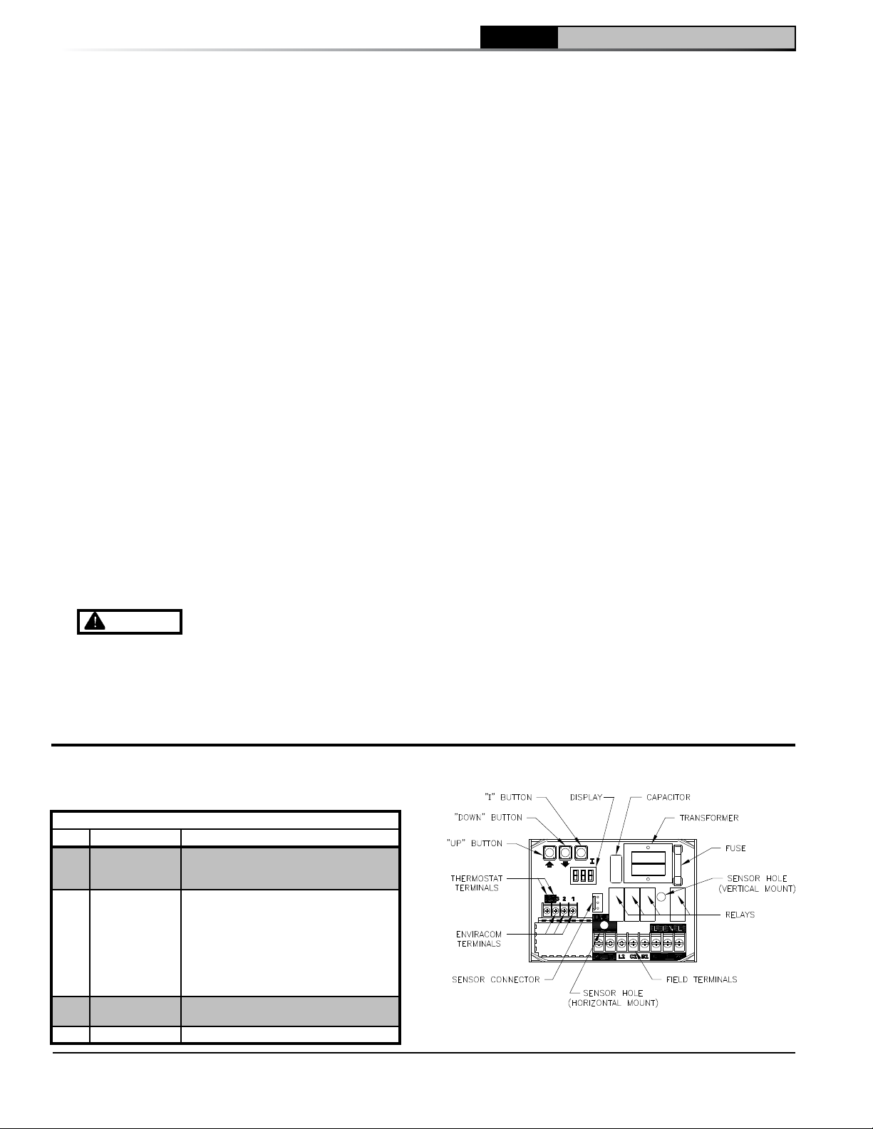
CL Installation & Service Manual
5 System Start-Up (continued)
• If safety switch shuts down burner and
resistance is above 1600 OHMS, open
line switch to boiler. Access cad cell
under ignitor, clean face of cad cell
and see that cell is securely in socket.
Check gasket around perimeter of ignitor
lid for proper seal. If gasket is missing
or damaged, replace gasket. Room light
can effect cad cell resistance. Reset
safety switch.
• Close line switch to boiler. If burner starts
and runs beyond safety switch cut-off
time, cell is good. If not, install new cell.
• Close hand valve in oil supply line.
• Failure occurs, device enters Recycle
Mode.
• Device tries to restart system after
approximately 60 seconds.
• After third Recycle Mode trial, safety
switch locks out within safety switch
timing indicated on label and control
enters Restricted Mode. Ignition and
motor stop and oil valves closes.
d. Power Failure Check: After Flame is
established, turn the power off to the
control/burner. The burner should shut
down safely. When power is restored a
normal ignition sequence should be started.
WARNING
removed after this check.
4. Check High Limit
a. Adjust system thermostat(s) to highest
setting.
Cad Cell Jumper must be
b. Allow burner to run until boiler water
temperature exceeds high limit setting. The
burner should shut down and circulators
continue running.
c. Allow the temperature to drop below control
setting. The burner must restart.
d. Boiler installation is not considered
complete until this check has been made.
5. Check Low Water Cut-Off Control
a. Steam Boiler
Check Low Water Cut-off Control with water
level at normal water line (see Figure 1C).
Raise thermostat setting to allow burner to
operate. Open boiler drain to allow water
level to drop to bottom of sight glass until
burner operation is shut-down by low water
cut-off.
Close boiler drain and refill to normal water
line. Burner should automatically restart
during fill. Lower thermostat setting.
b. Water Boiler
Refer to Appendix "A" at the rear of this
manual.
6. Check operating control on boiler applications
equipped with tankless heater(s). With burner
off, draw hot water until burner starts, then turn
off hot water and check burner shut-down.
J. IF CONTROLS MEET REQUIREMENT outlined
in Paragraph I, allow boiler to operate for
approximately 30 minute, confirm the boiler and
system have no leaks.
K. IF CONTROLS DO NOT MEET
REQUIREMENTS outlined in Paragraphs I-1
thru I-6, replace control and repeat checkout
procedures.
6 Operating
Table 7: Sequence of Operation
Status Codes Displayed in Mode
38
Status Description
Standby
(burner off,
pump off)
Standby
(burner off,
pump on)
Running
Self Test
No call for heat detected
Either condition is true:
a. Call for heat detected and boiler
temperature higher than operating
setpoint.
b. Call for heat detected and boiler
temperature higher than 140 F and
Pump Pre-Purge Time has not
expired.
The burner runs until the call for heat is
satisfied.
Control internal checking
Figure 30: Intelligent Oil Boiler Control
103876-08 - 1/19
Page 39

6 Operating (continued)
A. WATER BOILERS SEQUENCE OF OPERATION
1. Water Boilers Without Tankless Heaters
(Cold Start), Sequence Of Operation:
a. The CL Boiler is equipped with an Intelligent
Oil Boiler Control (Cold Start Boiler Control).
The boiler control replaces the traditional
electronic aquastat and circulator relays
and adds energy saving thermal purge
features. Energy is saved by starting the
circulator and delaying the burner start
when there is residual heat available in the
boiler.
b. The boiler’s sequence of operation is shown
as Status Codes on Boiler Control display.
See Table 7 and Figure 30.
c. When the thermostat calls for heat the
boiler control starts the system circulator
and the thermal purge (circulator pre-purge
time) begins. If the time is completed or
boiler temperature is less than the Start
Temperature (140 F default) the start
sequence continues by energizing the oil
primary to operate the following sequence:
blower is started and operates for prepurge time; spark is energized and fuel
valve is opened for ignition trial time; burner
fires until the thermostat is satisfied.
d. If the thermostat is not satisfied and the
Operating Setpoint (SP) is reached the
system circulator will continue to operate
and the burner will stop. When the boiler
water temperature drops below the setpoint
less the differential setting the burner will
restart.
e. After the thermostat is satisfied the burner
and circulator are stopped.
f. When an indirect water heater aquastat call
for heat is wired to the “ZR” terminal the
Boiler Control starts a domestic hot water
circulator connected to the “ZC” terminal
and when the boiler temperature is less than
Operating Setpoint (SP), the boiler control
energizes the oil primary to turn on the
burner without circulator pre-purge delay.
g. On burner start, if the CAD cell does not
see flame within approximately 15 seconds,
primary control will shut down the burner
and enter into a lockout mode. A lockout is
reset by pressing the reset button located
on the primary control. If the flame is lost
while the burner is firing, the primary control
shuts down the burner, enters a 60 second
recycle delay, and repeats the ignition
sequence. If after three (3) trials for ignition,
CL
flame is not detected, primary control will
enter into restricted mode. Restricted mode
is reset by holding down the reset button for
15 seconds.
2. Water Boilers with Tankless Heaters (Warm
Start), Sequence Of Operation:
a. The CL Boiler is equipped with a Warm
Start Intelligent Oil Boiler Control (Warm
Start Boiler Control). The Warm Start Boiler
Control replaces the traditional high and low
limit aquastat and circulator relays.
b. The boiler’s sequence of operation is shown
as Status Codes on Boiler Control display.
See Table 7 and Figure 30.
c. When the thermostat calls for heat the boiler
control starts the system circulator and the
start sequence continues by energizing
the oil primary to operate the following
sequence: blower is started and operates
for pre-purge time; spark is energized and
fuel valve is opened for ignition trial time;
burner fires until the thermostat is satisfied.
Optionally, the thermal purge (circulator
pre-purge time) maybe added adjusting
the Circulator Pre-purge time parameter.
This feature saves energy by starting the
circulator and delaying the burner start
when there is residual heat available in the
boiler .
d. If the thermostat is not satisfied and the
Operating Setpoint (SP) is reached the
system circulator will continue to operate
and the burner will stop. When the boiler
water temperature drops below the setpoint
less the differential setting the burner will
restart.
e. After the thermostat is satisfied the burner
and circulator are stopped.
f. The Warm Start Boiler Control also includes
a low limit control function. When the
boiler water temperature falls below the
Low Limit Setpoint less the Low Limit
Differential the “ZC” terminal and System
Circulator outputs are de-energized and
the oil primary is energized to start the
burner. As temperature rises above the Low
Limit Setpoint the burner is stopped, the
“ZC” output is energized and the System
Circulator is enabled to run in response to a
call for heat.
g. On burner start, if the CAD cell does not
see flame within approximately 15 seconds,
primary control will shut down the burner
and enter into a lockout mode. A lockout is
Installation & Service Manual
103876-08 - 1/19
39
Page 40
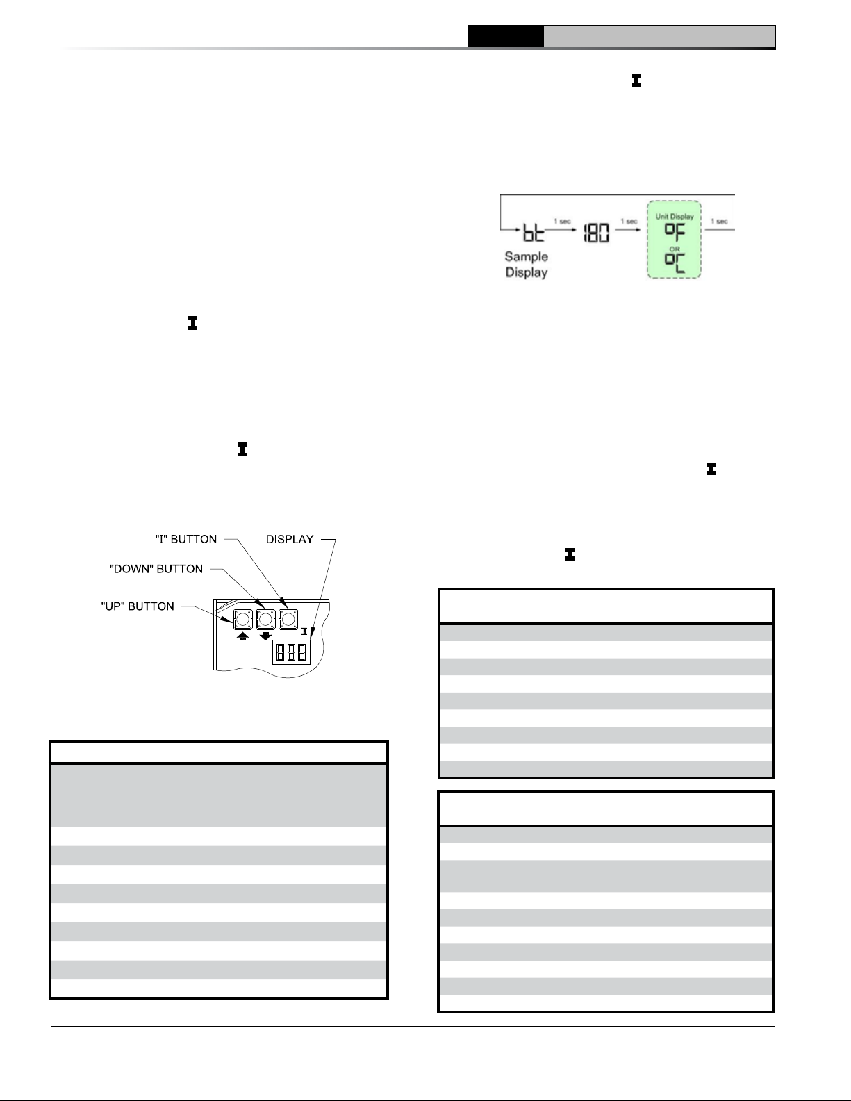
CL Installation & Service Manual
6 Operating (continued)
reset by pressing the reset button located
on the primary control. If the flame is lost
while the burner is firing, the primary control
shuts down the burner, enters a 60 second
recycle delay, and repeats the ignition
sequence. If after three (3) trials for ignition,
flame is not detected, primary control will
enter into restricted mode. Restricted mode
is reset by holding down the reset button for
15 seconds.
3. Using Boiler Control
The Boiler Control is located on front of boiler.
The Boiler Control display, along with Up
Down ò, and “I” keys may be used to view
boiler operating status (Figure 31).
4. Viewing the Operating Mode Options
In operating mode the user may view (but not
change) boiler operating status, settings and
troubleshooting information. To view Boiler
Control display information:
Press and release the “I” key on the Boiler
Control to change from one parameter to
the next. Each setting will alternately flash
between the relevant display code and its
corresponding value.
ñ,
For example, when the “
I” key is pressed
on the Boiler Control until “bt” is displayed,
it will then flash a three digit number (such
as “0”) followed by either “F” (or “C”). This
indicates that the boiler water temperature is
180°F. Other operating parameters display the
information in a similar fashion.
Please note that in operating mode to hold the
display on the value the user can press and
hold either the Up ñ or Down ò keys and the
value will be continuously shown. This may be
helpful in watching a value “live”.
5. Changing the Adjustable Parameters
To adjust parameters such as the High Limit
Setpoint and High Limit Differential:
a. Using the Boiler Control display, access
the adjustment mode by pressing and
holding the Up ñ, Down ò, and “I” keys
simultaneously for three (3) seconds.
This procedure is intended to discourage
unauthorized changes or accidental
changes to limit settings.
b. Press the "
I" key to display available
Adjustment Mode options. Select an option.
Figure 31: Boiler Control
Key Function & Orientation
Operating Mode Options
Status Numbers:
Standby
t
Running
Self Test
Boiler Temperature
bt
Operating Setpoint (Outdoor Reset)
P
High Limit Setting
HL
High Limit Differential
HdF
Low Limit Setpoint (warm start only)
LL
Low Limit Differential (warm start only)
LdF
Heat Request Status
hr
DHW Request Status
dh
Boiler Error
Err
Cold Start Boiler Control
Adjustment Mode Options
HL_
HdF
ZC_ dh, ZR or ELL
Or_ 0-10 minutes
PP_ 2-20 minutes
t_ 140 - 180°F
Pt_ On or Off
f-C F or C
bac
140-240°F Adjust High Limit Setting
10-30°F Adjust High Limit Differential
Warm Start Boiler Control
Adjustment Mode Options
HL_
LL_
Ldf
ZC_ ZR or dh
Or_
PP_
t_
Pt_ On or Off
f-C F or C
bac
140-240°F Adjust High Limit Setting
110-220°F Adjust Low Limit Setting
10-25°F
0-10 minutes Pump Overrun Time
0-20 minutes Pump Pre-purge Time
140 - 180°F Start Temperature
ZC and ZR Terminal Function
Pump Overrun Time
Pump Pre-purge Time
Start Temperature
Priority Time
Select degrees F or C Mode
Back to Operating Mode
Adjust Low Limit Differential
Setting
ZC and ZR Terminal Function
Priority Time
Select degrees F or C Mode
Back to Operating Mode
40
103876-08 - 1/19
Page 41
CL
Installation & Service Manual
6 Operating (continued)
c. Press the Up ñ and Down ò keys to adjust
the displayed setpoint to the desired value.
d. To return to the normal operating mode from
the Adjustment Mode, when the "bc” option
is displayed, press either the Up ñ or Down
ò key. If no keys are pressed, after five (5)
minutes the Boiler Control will automatically
return to the Operating Mode.
6. More Information about Adjustable Parameters
a. High Limit (HL_)
The Boiler Control is factory programmed
with a High Limit Setpoint of 180°F. The
boiler turns "off" when the boiler water
temperature (bt) is above this value. The
High Limit setpoint is adjustable between
140° and 240°F. The Operating Setpoint
(P) will equal the High Limit Setpoint.
b. High Limit Differential (HdF)
i. The Cold Start Boiler Control is factory
programmed with a Differential of
15°F. The Differential is the number of
degrees the boiler temperature must
decrease below the Operating Setpoint
before the boiler can restart. The
differential is adjustable between 10°
and 30°F.
ii. On Warm Start Boiler Control the High
Limit Differential is not adjustable and is
fixed at 10°F.
c. Low Limit (LL_)
The Warm Start Boiler Control is factory
programmed with a Low Limit Setpoint
of 110°F. On falling temperature the
boiler turns “on” and the “ZC” terminal
and System Circulator outputs are deenergized when the boiler temperature is
less than the Low Limit Setpoint less the
differential. On a rising temperature when
the boiler temperature is above the Low
Limit Setpoint the boiler turns “off”, the “ZC”
terminal output is energized and the System
circulator is enabled to respond to a call for
heat. The Low Limit Setpoint is adjustable
between 110°F and 220°F.
d. Low Limit Differential (Ldf)
The Warm Start Boiler Control is factory
programmed with a Low Limit Differential
Setpoint of 10°F. The Low Limit Differential
is the number of degrees the boiler
temperature must decrease below the Low
Limit Setpoint before the Warm Start Boiler
Control takes actions to warm the boiler.
These actions include starting the burner
and stopping water flow through the boiler.
The Low Limit Differential is adjustable
between 10°F and 25°F.
e. Circulator Overrun Time (OR_)
Circulator Overrun Time (also called
“circulator off delay” or “circulator post
purge”) continues circulator operation after
a call for heat has ended, sending excess
heat from the boiler into the priority zone.
Ensure system piping and zone panel
settings allow water flow to the priority zone
after the call for heat ends. The Circulator
Overrun Time has a factor setting of 0
minutes and is field adjustable between 0
and 10 minutes.
f. Circulator Pre-Purge Time (PP_)
When the boiler is warm [boiler water
temperature higher than 140°F (adjustable
using Start Temperature parameter)] and
there is a thermostat call for heat, the
system circulator is started and boiler
firing is delayed pre-purge minutes. If the
temperature drops below 140°F or there is
a DHW Call for Heat the boiler is started
without delay. Additionally, the boiler is
started without delay if the thermostat call
for heat is initiated when the boiler water
temperature is less than 140°F. This feature
helps save energy by satisfying home
heating needs with residual boiler heat
rather than cycling the boiler. The Circulator
Pre-purge time has a factory setting of 2
minutes and is field adjustable between 2
and 20 minutes. Refer to Table 8.
The Warm Start Boiler Control Pre-purge
Time is factor set to 0 minutes.
Table 8: Circulator Pre-Purge Time Example,
Parameter PP_= 2 Minutes
ZC and ZR
Call for
Heat
Terminal
Function
Boiler
Temp.
Boiler Status,
(B1 Output)
(ZC_)
TT= on
TT = on
ZR = on
ZR = on
ZR = on
ZR = on
--
--
ZC_ = ZR
ZC_ = ZR
ZC_ = DH
ZC_ = DH
< 140 Start with no delay
>140 Start after 2 minute delay
<140 Start with no delay
>140 Start after 2 minute delay
<140 Start with no delay
>140 Start with no delay
103876-08 - 1/19
41
Page 42
CL Installation & Service Manual
6 Operating (continued)
g. Start Temperature (t_)
The amount of “Heat available” is calculated by
taking the difference between measured boiler
water temperature and the Start Temperature
setting. Useful “Heat Available” is dependent
on the type of heating emitter installed in the
home. Heat emitters require a certain minimum
temperature to operate effectively. Our default
settings reflect cast iron radiators. Fan Coils
may require a start temperature setting of 180°F
or 160°F before providing heat to the home.
The Start Temperature has a factory setting of
140°F and is field adjustable between 140°F
and 180°F.
h. Priority Time (Pt_)
When the Priority Time parameter is set to “on”
and Domestic Hot Water (DHW) call for heat
is “on” the DHW demand will take “Priority”
over home heating demand and the system
circulator will be forced “off”. Priority Time
ends and the system circulator is released to
service home heating demand when Domestic
Hot Water call for heat is over. When Priority
Time parameter is set to “Off” the DHW call for
heat does not force “off” the system circulator.
The Priority Time has a factory setting of “On”
and is field adjustable between “On” and “Off”
Refer to Table 9.
i. ZC and ZR Terminal Function (ZC_)
The boiler control allows configuration of the
ZC output functionality to help the CL integrate
into each installation more effectively. The
ZC output can be connected to a domestic
hot water circulator or a second heating zone
circulator or be used to enable pumps in a
warm start application. These applications
are selected as follows:
i. When ZC_ is set equal to Domestic Hot
Water Demand (dh)
When there is an Indirect Water Heater
(IWH) the boiler control provides a “ZR”
input terminal for the IWH Aquastat
and “ZC” output terminal for the DHW
Circulator. When there is a DHW call for
heat, the System Circulator is “forced off”,
the DHW Circulator terminal is energized
and the circulator pre-purge time delay
control logic is bypassed to allow the
boiler to fire without delay. When DHW
demand ends the System Circulator
“force off” is removed, the circulator can
respond normally, and the DHW Circulator
is de-energized. The DHW call for heat
is detected by a voltage on to the "ZR"
terminal. When a Priority Time parameter
is set to “off” the System Circulator is not
forced off for a DHW call for heat. Refer
to Table 9.
Table 9: Domestic Hot Water Demand,
(Parameter ZC_= DH)
Call for Heat
T- T
InputZRInput
on off
on on
off on
on off
on on
off on
Priority
Time
(Pt_)
On
On
On
OFF
OFF
OFF
Circulator Status
System
Circulator
Output
on off
off on
off on
on off
on on
off on
ii. When ZC_ is set equal to Zone Request
(ZR)
When there is no IWH the Cold Start Boiler
Control “ZC” output may be configured
to control a second heating zone. This is
particularly helpful when the home uses
only two heating zones. The boiler control
replaces the need for a two circulator zone
panel. When DHW Terminal Function
(dh_) is set to ZR the boiler control’s two
circulator outputs are used to control two
independent heating zones. Refer to Table
10. A "TT" input causes a call for heat and
energizes the System Circulator output to
service heating zone 1. A second zone’s
thermostat may be wired to the "ZR" input
to energize heating zone 2 circulator wired
to the "ZC" output. Both outputs function
independently, "TT" input controls only the
System Circulator output and the "ZR" input
controls only the "ZC" output. Both inputs
cause a boiler call for heat.
The Warm Start Boiler Control with ZC_ set
equal to Zone Request (ZR) energizes the
"ZC" terminal while the boiler is warm as
described earlier in this section (refer to
Paragraph A,2,f). The "ZR" input is a call
for heat that starts the boiler.
iii. External Low Limit, Parameter ZC = ELL
The Cold Start Boiler Control is capable of
functioning as a warm start control when
external limit control is installed that closes
a contact when boiler water temperature
falls below a setpoint. When an external
DHW
Circulator
ZC Output
42
103876-08 - 1/19
Page 43
CL
Installation & Service Manual
6 Operating (continued)
Table 10: Zone Request, Parameter zc_= zr
Call for Heat Circulator Status
T- T
Input
off off off off
on off on off
on on on on
off on off on
7. HydroStat 3250 Plus Sequence of Operation
a. Refer to the HydroStat Instructions
(P/N 104145-01) for all operational instructions.
2. Refer to the "IMPORTANT" notice below.
B. STEAM BOILERS SEQUENCE OF OPERATION
Upon a thermostat call for heat, when provided, the
Oil Primary Control is energized when the steam
pressure is below the L404F Pressure Limit and
water level is above the Low Water Cut-Off. When
energized the Oil Primary Control starts the burner
as follows; blower is started and operates for a
pre-purge time; spark is energized and fuel valve is
opened for ignition trail time; the fuel valve remains
open when flame is proven. The burner fires until
the thermostat is satisfied or the Pressure Limit
ZR
Input
limit contact closes (boiler water is cold)
the boiler is started and the "ZC" and "C1"
output terminals are de-energized. When
the "ZR" terminal is de-energized (boiler
water temperature is above setpoint)
the call for heat is ended and the "C1"
terminal is released to operation and the
"ZC" terminal is energized. An External
Low Limit Request is detected by sensing
a voltage on the "ZR" terminal. The Warm
Start Boiler Control does not have the
External Low Limit Option. Refer to Table
11.
C1
Output
ZC
Output
Table 11: External Low Limit,
Parameter zc_= ell
Call for Heat Circulator Status
T- T
Input
off off off on
on off on on
on on off off
off on off off
setting is reached. The Oil Primary Control stops the
burner by closing the fuel valve and operating the
blower for post-purge time. Upon a drop in pressure,
steam pressure below the L404F Pressure Limit, the
burner will re-start if the thermostat is still calling for
heat. When there is a tankless heater included and
there is no demand for heat, the L4006A operating
control will maintain the boiler water temperature
at the selected setting for proper operation of the
domestic water heater.
The probe low water cut-off will shut down the burner
after a 10 second delay, if the water level in the boiler
drops below the probe level. If the water level is too
low the burner will not be allowed to restart. The low
water cut-off will reset and restart the burner with a
call for heat 30 seconds after the water is returned
to its normal level.
On burner start, if the CAD cell does not see flame
within approximately 15 seconds, primary control
will shut down the burner and enter into a lockout
mode. A lockout is reset by pressing the reset button
located on the primary control. If the flame is lost
while the burner is firing, the primary control shuts
down the burner, enters a 60 second recycle delay,
and repeats the ignition sequence. If after three
(3) trials for ignition, flame is not detected, primary
control will enter into restricted mode. Restricted
mode is reset by holding down the reset button for
15 seconds.
ZR
Input
C1
Output
ZC
Output
IMPORTANT
This boiler is equipped with a feature that saves energy by reducing the boiler water temperature as the heating
load decreases. This feature is equipped with an override which is provided primarily to prevent the use of an
external energy management system that serves the same function. THIS OVERRIDE MUST NOT BE USED
UNLESS AT LEAST ONE OF THE FOLLOWING CONDITIONS IS TRUE:
• An external energy management system is installed that reduces the boiler water
temperature as the heating load decreases.
• This boiler is not used for any space heating.
• This boiler is part of a modular or multiple boiler system having a total input of
300,000 BTU/HR or greater.
• This boiler is equipped with a tankless coil.
103876-08 - 1/19
43
Page 44
CL Installation & Service Manual
7 Maintenance and Service Instructions
A. MAINTENANCE OF LOW WATER CUT-OFF
DEVICES
WARNING
cut-off devices require annual inspection and
maintenance.
1. Although these devices are solid state in their
operation, the probe is exposed to possible
contamination in the boiler water and subject
to fouling.
2. It is important to physically remove the probe
from the boiler tapping annually and inspect
that probe for accumulation of scale or
sediment.
3. Follow these steps to inspect, clean and/or
replace the probe:
a. Turn off electric service to the boiler.
b. Drain boiler water to a level below the
tapping for the probe.
DANGER
at zero pressure before removing the LWCO
probe. DO NOT rely on the pressure gauge
to indicate that the boiler is at zero pressure.
Open the safety valve to relieve all internal
pressure prior to proceeding. Safety valve
discharge piping must be piped such that the
potential for burns is eliminated.
c. Disconnect wiring connections between the
low water cut-off control and the probe.
d. Remove the low water cut-off control from
the probe.
e. Unscrew the probe from the boiler tapping.
f. Inspect that portion of the probe that is
exposed to the boiler water for a scale or
sediment buildup.
g. Light deposits may be removed by wiping
the probe with a damp cloth. Wiping the
probe with a cloth soaked in vinegar will
remove more tenacious lime deposits. The
most stubborn deposits may be removed
from the probe by using a diluted amount, 3
parts of water to 1 part of phosphoric acid
(H2PO4).
CAUTION
handling phosphoric acid and follow the
instruction label on its container.
h. Clean the pipe threads of the probe to
remove old, hardened pipe dope and other
foreign matter.
i. Apply a moderate amount of good quality
pipe dope to the pipe threads on the probe,
Probe and float type low water
Assure that the boiler is
Exercise caution when
leaving the two end threads bare. DO NOT
use PTFE (Teflon) tape.
j. Screw the probe into the boiler tapping.
k. Mount the low water cut-off control on the
probe.
l. Reconnect the control to probe wiring.
m. Fill the boiler to its normal waterline.
n. Add boiler water treatment compound as
needed (refer to Paragraph B.).
o. Restore electric service to the boiler.
p. Fire burner to bring the water in the boiler to
a boil to drive off free oxygen.
q. WARNING — BEFORE RETURNING
BOILER TO SERVICE: Follow the low water
cut-off check out procedure in Section V
"System Start-Up", Paragraph I, Step 5.
B. BOILER AND SYSTEM CLEANING
INSTRUCTIONS FOR TROUBLE FREE
OPERATION.
1. Steam Boilers:
a. Oil, greases & sediments which accumulate
in a new boiler and piping must be removed
from the system in order to prevent an
unsteady water line and carry over of the
water into the supply main above boiler.
Operate the boiler with steam in the
entire system for a few days allowing the
condensate to return to the boiler. If the
condensate can temporarily be wasted,
operate boiler only for the length of time
it takes for condensate to run clear. If
the latter cannot be achieved or if the
condensate is returned to the boiler, boil out
the boiler using the SURFACE BLOW-OFF
connection.
i. Drain boiler until 1” of water is visible
in gauge glass. Run temporary 1½”
NPT pipe line from the surface blow-off
connection to an open drain or some
other location where hot water may be
discharged safely. DO NOT install valve
in this line.
ii. Drain about 5 gallons of hot water
from boiler into a container and
dissolve into it an appropriate amount
of recommended boil out compound.
Remove safety valve & add solution to
boiler water thru exposed tapping using
a funnel.
NOTICE Check with local authorities or consult
local water treatment services for acceptable
chemical cleaning compounds.
44
103876-08 - 1/19
Page 45

CL
Installation & Service Manual
7 Maintenance and Service Instructions (continued)
iii. Start burner and operate sufficiently to
boil the water without producing steam
pressure. Boil for about 5 hours. Open
boiler feed pipe sufficiently to permit a
steady trickle of water from the surface
blow-off pipe. Continue this slow boiling
and trickle of overflow for several hours
until the water coming from the overflow
is clear.
iv. Stop burner and drain boiler in a
manner and to a location that hot water
can be discharged with safety.
v. Refill boiler to normal water line. If water
in gauge glass does not appear to be
clear, repeat steps (i. thru iii.) and boil
out the boiler for a longer time.
b. Low pressure steam boilers such as the
CL Series should be maintained with
appropriate water treatment compounds.
Add suitable water treatment compounds
as recommended by your qualified water
treatment company.
c. Remove temporary surface blow-off piping,
plug tapping and reinstall safety valve.
Boil or bring water temperature to 180°F
promptly in order to drive off the dissolved
gases in the fresh water.
d. If unsteady water line, foaming or priming
persist, install gate valve in Hartford Loop
and drain valves in return main and at boiler
as shown in Figure 13 and proceed as
follows:
i. Connect hoses from drain valves to floor
drain. Close gate valve in Hartford Loop
and open drain valve in return main. Fill
boiler to normal water level, turn on oil
burner and operate boiler at this water
level for at least 30 minutes after the
condensate begins to run hot, then turn
off burner.
Close all radiator valves. Remove all
supply main air valves and plug the
openings in supply main.
ii. Draw about 5 gallons of hot water from
boiler into a container and dissolve
into it the appropriate amount of a
recommended boilout compound.
Remove safety valve from boiler and
pour this solution into boiler, then
reinstall safety valve.
iii. Turn on oil burner and keep operating
while feeding water to boiler slowly. This
will raise water level in boiler slowly so
that water will be boiling hot and will
rise slowly into supply main and back
through return main, flowing from drain
103876-08 - 1/19
hose at about 180°F. Continue until
water runs clear from drain hose for at
least 30 minutes.
iv. Stop feeding water to boiler but
continue operating oil burner until
excess water in boiler flows out through
supply main and water lowers (by
steaming) until it reaches normal level
in boiler. Turn off oil burner. Drain boiler.
Open all radiator valves. Reinstall all
supply main air valves. Open gate valve
in Hartford Loop.
v. When boiler has cooled down
sufficiently (crown sheet of sections are
not too hot to touch), close the drain
valves at boiler and in return main and
feed water slowly up to normal level
in boiler. Turn on oil burner and allow
boiler to steam for 10 minutes, then turn
off burner. Draw off one quart of water
from bottom gauge glass fitting and
discard. Draw off another quart sample
and if this sample is not clear, repeat
the cycle of draining the boiler and
return main and refilling the boiler until
sample is clear.
vi. If the boiler water becomes dirty
again at a later date due to additional
sediment loosened up in the piping,
close gate valve in Hartford Loop, open
drain valve in return main, turn on oil
burner and allow Condensate to flow
to drain until it has run clear for at least
30 minutes while feeding water to boiler
so as to maintain normal water level.
Turn off oil burner, drain boiler, open
gate valve in Hartford Loop, then repeat
the full "Boiler and System Cleaning"
procedure outlined in Paragraph B
starting on Page 43.
e. Make pH or Alkalinity Test.
After boiler and system have been cleaned
and refilled as previously described, test
the pH of the water in the system. This can
easily be done by drawing a small sample
of boiler water and testing with hydrion
paper which is used in the same manner
as litmus paper, except it gives specific
readings. A color chart on the side of the
small hydrion dispenser gives the reading
in pH. Hydrion paper is inexpensive and
obtainable from any chemical supply house
or through your local druggist. The pH
should be higher than 7, but lower than 11.
Add some of the washout chemical (caustic
soda), if necessary, to bring the pH within
the specified range.
45
Page 46
7 Maintenance and Service Instructions (continued)
CL Installation & Service Manual
f. Boiler is now ready to be put into service.
2. Water Boilers:
a. Filling of boiler and system.
General — In a hot water heating system,
the boiler and entire system (other than
the expansion tank) must be full of water
for satisfactory operation. Water should
be added to the system until the boiler
pressure gauge registers 12 psi. To insure
that the system is full, water should come
out of all air vents when opened.
b. Boiling out of boiler and system. The oil
and grease which accumulate in a new
hot water boiler can be washed out in the
following manner:
i. Remove relief valve using extreme care
to avoid damaging it.
ii. Add an appropriate amount of
recommended boil out compound.
iii. Replace relief valve.
iv. Fill the entire system with water.
v. Start firing the boiler.
vi. Circulate the water through the entire
system.
vii. Vent the system, including the radiation.
viii. Allow boiler water to reach operating
temperature, if possible.
ix. Continue to circulate the water for a few
hours.
x. Stop firing the boiler.
xi. Drain the system in a manner and
to a location that hot water can be
discharged with safety.
xii. Remove plugs from all available returns
and wash the water side of the boiler as
thoroughly as possible, using a highpressure water stream.
xiii. Refill the system with fresh water.
c. Add appropriate boiler water treatment
compounds as recommended by your
qualified water treatment company.
d. Make pH or Alkalinity Test.
After boiler and system have been cleaned
and refilled as previously described, test
the pH of the water in the system. This can
easily be done by drawing a small sample
of boiler water and testing with hydrion
paper which is used in the same manner
as litmus paper, except it gives specific
readings. A color chart on the side of the
small hydrion dispenser gives the reading
pH. Hydrion paper is inexpensive and
obtainable from any chemical supply house
or through your local druggist. The pH
should be higher than 7 but lower than 11.
Add some of the washout chemical (caustic
soda), if necessary, to bring the PH within
the specified range.
e. Boiler is now ready to be put into service.
3. Excessive Make-up Water
A leaky system will increase the volume of
make-up water supplied to the boiler, which
can significantly shorten the life of the boiler.
Entrained in make-up water are dissolved
minerals, salts and oxygen. When the fresh,
cool make-up water is heated in the boiler, the
minerals fall out as sediment, the salts coat the
inside of the boiler, and the oxygen escapes
as a gas. The accumulation of sediment
eventually isolates the water from contacting
the cast iron. When this happens the cast iron
in that area gets extremely hot and eventually
cracks. The presence of free oxygen or
chloride salts in the boiler corrodes the cast
iron from the inside. More make-up water and
higher concentrations of contaminants damage
the boiler sooner. Our warranty does not cover
corrosion and sediment-related damage.
Clearly it is in everyone’s best interest to
prevent this type of failure. You can do your
part by ensuring that your system is leak-free,
keeping leakage to less than 2 percent of the
boiler water volume each month.
IMPORTANT
IF, DURING NORMAL OPERATION, IT IS
NECESSARY TO ADD MORE WATER THAN
INDICATED BELOW, CONSULT A QUALIFIED
SERVICE TECHNICIAN TO CHECK YOUR SYSTEM
FOR LEAKS.
Model No.
CL3 0.3 4
CL4 0.4 5
CL5 0.5 6
C. ATTENTION TO BOILER WHILE NOT IN
OPERATION
1. Important
If boiler is not used during winter time, it must
be fully drained to prevent freeze damage.
2. Spray inside surfaces with light lubricating or
crankcase oil using gun with extended stem so
as to reach all corners.
Gallons Per
Month
Gallons Per
Year
46
103876-08 - 1/19
Page 47
7 Maintenance and Service Instructions (continued)
CL
Installation & Service Manual
3. With steam boilers, at end of season add
sufficient water to fill boiler to top of water
column and leave it that way until fall when
water should be drained again to proper level.
If, at this time, boiler water is dirty, drain water,
flush out boiler, and refill with clean water to
prescribed water level.
4. Always keep the manual fuel supply valve shut
off if the burner is shut down for an extended
period of time.
5. To recondition the heating system in the fall
season after a prolonged shut down, follow the
instructions outlined in Section V, Paragraphs A
through K.
8 Boiler Cleaning
WARNING
A. CLEAN THE FLUEWAYS (See Figure 32).
1. Disconnect oil line(s) and remove burner and
burner mounting plate. See Figures 1A thru
1C.
2. Lay protective cloth or plastic over combustion
chamber blanket.
3. Remove the smokepipe as necessary to gain
access to the boiler canopy.
4. Remove the jacket top panels.
5. Remove the canopy being careful not to
damage the cerafelt gasket.
6. Using a 1¼” diameter wire or fibre bristle brush
(30” handle) clean the flueways. Brush from the
top using diagonal strokes for best results. DO
NOT allow brush to strike the target wall or liner
in the chamber.
B. CLEAN TOP OF BOILER SECTIONS.
1. Brush and vacuum the tops of the boiler
sections.
C. CLEAN THE FIREBOX.
1. Using wire or fibre bristle brush, clean crown of
boiler and inside of water legs. DO NOT allow
brush to strike target wall or blanket in the
combustion chamber.
D. AFTER CLEANING, remove protective cloth
with debris and vacuum as necessary, but be
careful not to damage blanket. Inspect target
wall, combustion chamber blanket and burner
mounting plate insulation for signs of damage. If
damaged, replace as needed.
All boiler cleaning must be completed with burner service switch turned off.
WARNING
which may cause the boiler to shut down and
not restart without service. If damage due to
frozen pipes is a possibility, the heating system
should not be left unattended in cold weather;
or appropriate safeguards and alarms should
be installed on the heating system to prevent
damage if the boiler is inoperative.
E. REASSEMBLE BOILER.
CAUTION: Do not start the burner unless canopy,
smokepipe and burner swing door are secured in
place.
1. Install the canopy taking care to align the
gaskets without blocking the flueways. If
gasket is damaged, replace as needed.
2. Close and secure burner swing door to front
section with fasteners.
3. Reconnect oil line(s).
4. Reinstall Top Panels and secure with sheet
metal screws.
5. Reinstall smokepipe on canopy and secure to
collar with sheet metal screws.
WARNING
to an approved chimney in good condition.
Serious property damage could result if the
boiler is connected to a dirty or inadequate
chimney. The interior of the chimney flue must
be inspected and cleaned before the start of
the heating season and should be inspected
periodically throughout the heating season for
any obstructions. A clean and unobstructed
chimney flue is necessary to allow noxious
fumes that could cause injury or loss of
life to vent safely and will contribute toward
maintaining the boiler's efficiency.
This boiler contains controls
The boiler must be connected
103876-08 - 1/19
47
Page 48
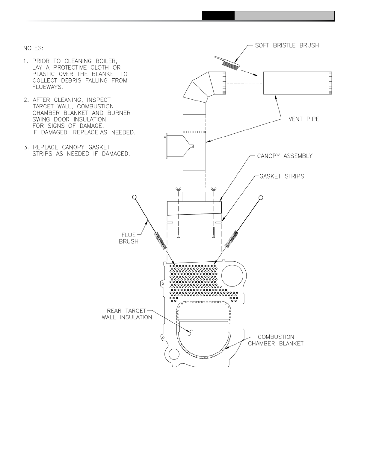
8 Boiler Cleaning (continued)
CL Installation & Service Manual
48
Figure 32: Cleaning of Boiler Flueways
103876-08 - 1/19
Page 49
CL
Installation & Service Manual
8 Boiler Cleaning (continued)
Important Product Safety Information
Refractory Ceramic Fiber Product
WARNING
has been classified as a possible human carcinogen. When exposed to temperatures above 1805F,
such as during direct flame contact, RCF changes into crystalline silica, a known carcinogen. When
disturbed as a result of servicing or repair, these substances become airborne and, if inhaled, may be
hazardous to your health.
Precautionary Measures:
Do not remove or replace RCF parts or attempt any service work involving RCF without wearing the
following protective gear:
1. A National Institute for Occupational Safety and Health (NIOSH) approved respirator
2. Long sleeved, loose fitting clothing
3. Gloves
4. Eye Protection
The Repair Parts list designates parts that contain refractory ceramic fibers (RCF)
AVOID Breathing Fiber Particulates and Dust
• Take steps to assure adequate ventilation.
• Wash all exposed body areas gently with soap and water after contact.
• Wash work clothes separately from other laundry and rinse washing machine after use to avoid
contaminating other clothes.
• Discard used RCF components by sealing in an airtight plastic bag. RCF and crystalline silica
are not classified as hazardous wastes in the United States and Canada.
First Aid Procedures:
• If contact with eyes: Flush with water for at least 15 minutes. Seek immediate medical
attention if irritation persists.
• If contact with skin: Wash affected area gently with soap and water. Seek immediate
medical attention if irritation persists.
• If breathing difficulty develops: Leave the area and move to a location with clean fresh air.
Seek immediate medical attention if breathing difficulties persist.
• Ingestion: Do not induce vomiting. Drink plenty of water. Seek immediate medical
attention.
103876-08 - 1/19
49
Page 50

9 Troubleshooting
CL Installation & Service Manual
A. COMBUSTION
1. Nozzles — Although the nozzle is a relatively
inexpensive device, its function is critical to
the successful operation of the oil burner.
The selection of the nozzle supplied with the
CL boiler is the result of extensive testing
to obtain the best flame shape and efficient
combustion. Other brands of the same spray
angle and spray pattern may be used but may
not perform at the expected level of CO2 and
smoke. Nozzles are delicate and should be
protected from dirt and abuse. Nozzles are
mass-produced and can vary from sample to
sample. For all of those reasons a spare nozzle
is a desirable item for a serviceman to have.
2. Fuel Leaks — Any fuel leak between the pump
and the nozzle will be detrimental to good
combustion results. Look for wet surfaces in
the air tube, under the ignitor, and around the
air inlet. Any such leaks should be repaired as
they may cause erratic burning of the fuel and
in the extreme case may become a fire hazard.
3. Suction Line Leaks — Any such leaks should
be repaired, as they may cause erratic burning
of the fuel and in extreme cases may become
a fire hazard. Whatever it takes, The Oil Must
Be Free of Air. This can be a tough problem,
but it must be resolved. Try bleeding the pump
through a clear tube. There must be no froth
visible. There are various test kits available
to enable you to look at the oil through clear
tubing adapted to the supply line at the pump
fitting. Air eliminators are on the market that
have potential. Also, electronic sight glasses
are being used with good success. At times,
new tubing must be run to the tank or new
fittings put on. Just make sure you get the air
out before you leave.
Any air leaks in the fuel line will cause an
unstable flame and may cause delayed ignition
noises. Use only flare fittings in the fuel lines.
4. Gasket Leaks — If 11.5 to 12.5% CO2 with a #1
smoke cannot be obtained in the breeching,
look for air leaks around the burner mounting
gasket, observation door, and canopy gasket.
Such air leaks will cause a lower CO2 reading
in the breeching. The smaller the firing rate
the greater effect an air leak can have on CO2
readings.
5. Dirt — A fuel filter is a good investment.
Accidental accumulation of dirt in the fuel
system can clog the nozzle or nozzle strainer
and produce a poor spray pattern from the
nozzle. The smaller the firing rate, the smaller
50
the slots become in the nozzle and the more
prone to plugging it becomes with the same
amount of dirt.
6. Water — Water in the fuel in large amounts
will stall the fuel pump. Water in the fuel in
smaller amounts will cause excessive wear on
the pump, but more importantly water doesn’t
burn. It chills the flame and causes smoke and
unburned fuel to pass out of the combustion
chamber and clog the flueways of the boiler.
7. Cold Oil — If the oil temperature approaching
the fuel pump is 40°F or lower, poor
combustion or delayed ignition may result.
Cold oil is harder to atomize at the nozzle.
Thus, the spray droplets get larger and the
flame shape gets longer. An outside fuel
tank that is above grade or has fuel lines in a
shallow bury is a good candidate for cold oil.
The best solution is to locate the tank near the
boiler in the basement utility room or bury the
tank and lines deep enough to keep the oil
above 40°F. Check environmental issues with
local authorities having jurisdiction.
8. Fame Shape — Looking into the combustion
chamber through the observation port, the
flame should appear straight with no sparklers
rolling up toward the crown of the chamber.
If the flame drags to the right or left, sends
sparklers upward or makes wet spots on the
target wall, the nozzle should be replaced. If
the condition persists look for fuel leaks, air
leaks, water or dirt in the fuel as described
above.
9. High Altitude Installations — Air openings
must be increased at higher altitudes. Use
instruments and set for 11.5 to 12.5% CO2.
10. Start-up Noise — Late ignition is the cause
of start-up noises. If it occurs recheck for
electrode settings, flame shape, air or water in
the fuel lines.
11. Shut Down Noise — If the flame runs out of
air before it runs out of fuel, an after burn with
noise may occur. That may be the result of a
faulty cut-off valve in the fuel pump, or it may
be air trapped in the nozzle line. It may take
several firing cycles for that air to be fully
vented through the nozzle. Water in the fuel or
poor flame shape can also cause shut down
noises.
103876-08 - 1/19
Page 51

CL
Installation & Service Manual
9 Troubleshooting (continued)
NOTICE CHECK TEST PROCEDURE. A very
good test for isolating fuel side problems is
to disconnect the fuel system and with a 24"
length of tubing, fire out of an auxiliary five
gallon pail of clean, fresh, warm #2 oil from
another source. If the burner runs successfully
when drawing out of the auxiliary pail then
the problem is isolated to the fuel or fuel lines
being used on the jobsite.
B. OIL PRIMARY CONTROL (Oil Primary)
1. Burner (Oil Primary) will not come on.
a. No power to Oil Primary.
b. Oil Primary is in lockout or restricted mode.
Press reset button for one (1) second to exit
lockout. If control has recycled three times
within the same call for heat, it will enter into
restricted mode. To reset from restricted
mode, refer to Section V, Paragraph I, Step
2 for details.
c. CAD cell seeing light.
d. CAD assembly defective.
e. Control motor relay is stuck closed (see
note below).
2. Burner (control) will light, then shut down after
a short time, then restart after one (1) minute.
a. CAD cell is defective.
b. Air leaking into oil line causing flame out.
c. Defective nozzle causing flame to be
erratic.
d. Excessive airflow or draft causing flame to
leave burner head.
e. Excessive back pressure causing flame to
be erratic.
3. Control locks out after Trial For Ignition (TFI).
a. No oil to burner.
b. Shorted electrodes.
c. Nozzle clogged.
d. Airflow too high.
e. Ignitor module defective.
f. CAD cell defective.
g. Oil valve stuck open or closed.
Note: The Safety Monitoring Circuit (SMC) is
designed to provide lockout in the event
of a stuck or welded motor relay.
Also refer to Model EZ-1/2/3 Oil Burner -
Instruction Manual (Form #MNEZ123) for
additional information.
4. Carlin 70200 Oil Primary Control
a. Burner (control) will not come on.
i. No power to control.
ii. Control is in lockout. Press reset button
for one (1) second.
iii. CAD cell seeing light.
iv. CAD assembly defective.
v. Control motor relay is stuck closed (see
note below).
b. Burner (control) will light, then shut down
after a short time, then restart after one (1)
minute.
i. CAD cell is defective.
ii. Air leaking into oil line causing flame
out.
iii. Defective nozzle causing flame to be
erratic.
iv. Excessive airflow or draft causing flame
to be erratic.
v. Excessive back pressure causing flame
to be erratic.
c. Control locks out after Trial For Ignition (TFI).
i. No oil to burner.
ii. Shorted electrodes.
iii. Nozzle clogged.
iv. Airflow too high.
v. Ignitor module defective.
vi. CAD cell defective.
vii. Oil valve stuck open or closed.
Note: The Safety Monitoring Circuit (SMC)
is designed to provide lockout in the
event of a stuck or welded motor relay.
NOTICE If flame is not established within 15
seconds of oil valve actuation (known as Trial
For Ignition [TFI]) lockout will occur. Lockout
is indicated by a red LED solid-on located on
the oil primary control.
Hard Lockout will occur if the Oil Primary
Control locks-out three (3) times during a call
for heat. This is indicated by red light reset
button solid-on.
C. INTELLIGENT OIL BOILER CONTROL
• Cold Start Boiler Control is used on Boilers
without Tankless Heaters.
• Warm Start Boiler Control is used on Boilers
with Tankless Heaters
1. When a problem occurs with the boiler
operation, the Boiler Control easily provides
specific, valuable information to help resolve
the issue quickly. The display on the Boiler
Control should be the first place to check.
a. If an Error Code "Err" IS NOT displayed on
the Boiler Control: In this circumstance,
Table 12 can be used to determine the
problem and possible causes.
103876-08 - 1/19
51
Page 52
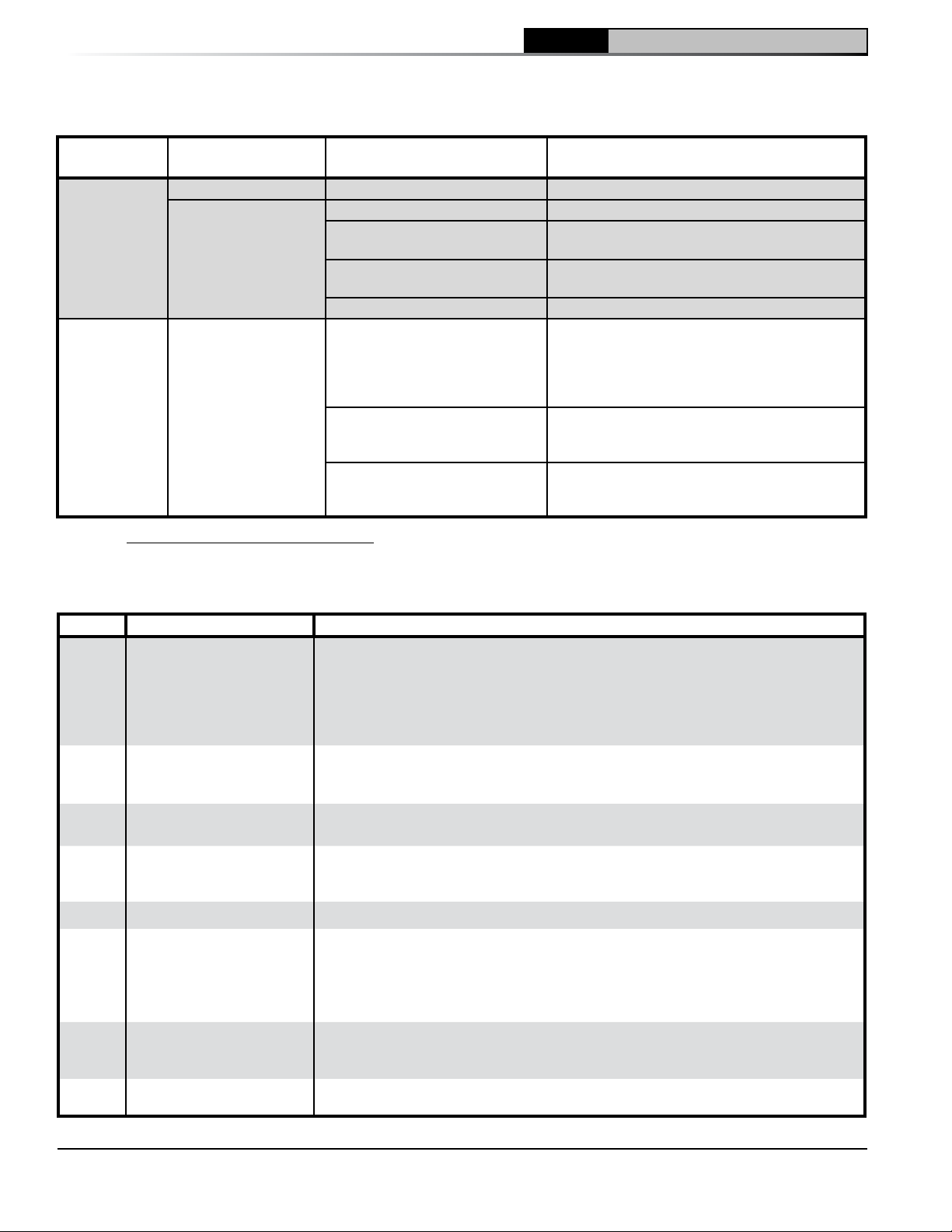
9 Troubleshooting (continued)
Table 12: Troubleshooting Guide
CL Installation & Service Manual
System
Condition
Boiler is cold,
house is cold.
Boiler is hot,
house is cold.
Diagnostic Condition Check Action
Display is OFF. 120 Vac System power. Turn system power on.
24 Vac T-T No 24 V; replace control.
Display is ON.
Display is ON.
24 V present; disconnect
thermostat, short T-T.
120 Vac at B1-B2
Refer to Err on display. -----
120 Vac at C1-C2
Boiler below the Low Limit
temperature, wait for boiler to go
above Low Limit temperature.
Boiler above LL? If yes, check
for 120 Vac between ZC and L2.
Boiler starts, check wiring and thermostat.
• If no, replace control.
• If yes, check burner and wiring.
• 120 Vac at C1-C2, check wiring to pump.
• Wiring OK, is pump running?
• If not, replace the pump.
• If pump is running, check for trapped air
or closed zone valves
• If no 120 Vac , replace control.
• If yes, check zone relays, circulators
and wiring.
b. If the Boiler Control detects an error it will flash "Err" (boiler control error) followed by a number. Use this
text and number to identify the boiler problem and corrective action in Table 13 below.
Table 13: Boiler Control Error Numbers
Display Status Recommended Corrective Actions
Temperature sensor failure, wire harness loose or shorted connection or control
hardware failure:
Err
Err 2
Err 3
Err 4
Err 5
Temperature Sensor Fault
Communication Fault
Internal Hardware Fault
Burner Output (B1) Fault
Line Voltage Fault (< 80 Vac) AC voltage out of specification high or low; check L1, L2, 110 VAC.
- Check sensor is securely attached to boiler control
- Check that sensor wire is not damaged
- If secure and in good condition, replace sensor
- If problem persists, replace control
Enviracom terminal is shorted to ground or line voltage.
- Check wiring to EnviraCOM terminals 1,2 and 3. Wiring to
external EnviraCom device is incorrect.
Error detected with AC power supply frequency or boiler control failure. Cycle power
to the control. Replace control if problem persists.
B1 output sensed powered during safety output relay check sequence or un-powered
during running, or powered in idle in combination with water temperature above 264°F
limit. Cycle power to the control. Replace control if problem persists.
-----
52
Err 6
Err
Err
Fuse missing
User settings lost, (reset to
factory defaults)
Manual Reset Lockout
(resettable)
Internal fuse is blown or missing. The fuse protects the Aquastat from miswiring the L1
and L2 on Oil Primary. When the Oil Primary is correctly wired the fuse is useless and
not detected. If Primary is wired incorrectly the fuse is blown out and Aquastat report
error 6. EnviraCOM message is sent when the wiring is fixed and the error disappears
to indicate the end of the error state. Check wiring and replace fuse.
Warning: Generated if user adjustments are lost and the device uses factory default
values. Error is cleared by entering and exiting the Adjustment mode. Replace control
if problem persists.
Set if Err 4 was invoked four times in a row. Check wiring and clear Lockout by
pressing all three user keys for 30 seconds.
103876-08 - 1/19
Page 53

CL
Installation & Service Manual
10 Repair Parts
All CL™ Series repair parts may be ordered through New Yorker Boiler Company, Inc., or its authorized distributors.
Should you require assistance in locating a New Yorker Distributor in your area, or have questions regarding the
availability of New Yorker products or repair parts, please contact: New Yorker Boiler Company, Inc., P.O. Box 3005,
Lancaster, PA 17604-3005, Attn: Customer Service Department. Visit our website at www.newyorkerboiler.com
103876-08 - 1/19
53
Page 54
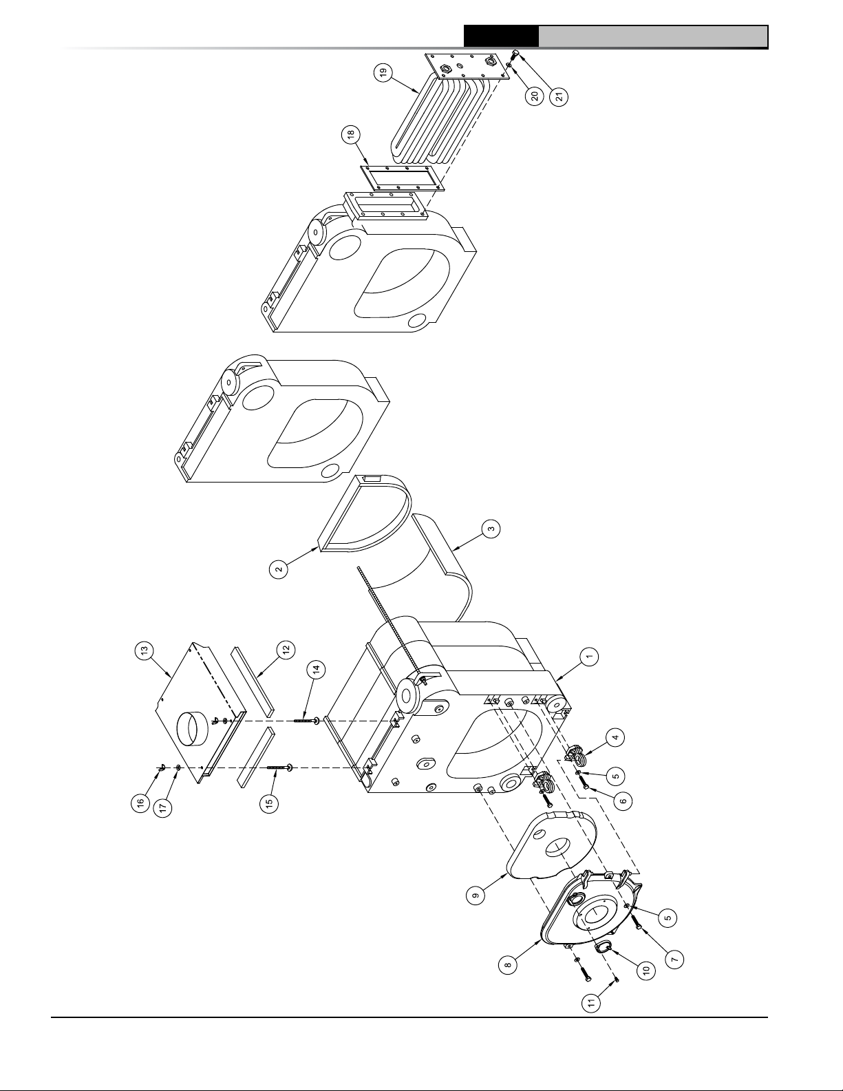
10 Repair Parts (continued)
CL Installation & Service Manual
54
Bare Boiler Assembly (Exploded View)
103876-08 - 1/19
Page 55
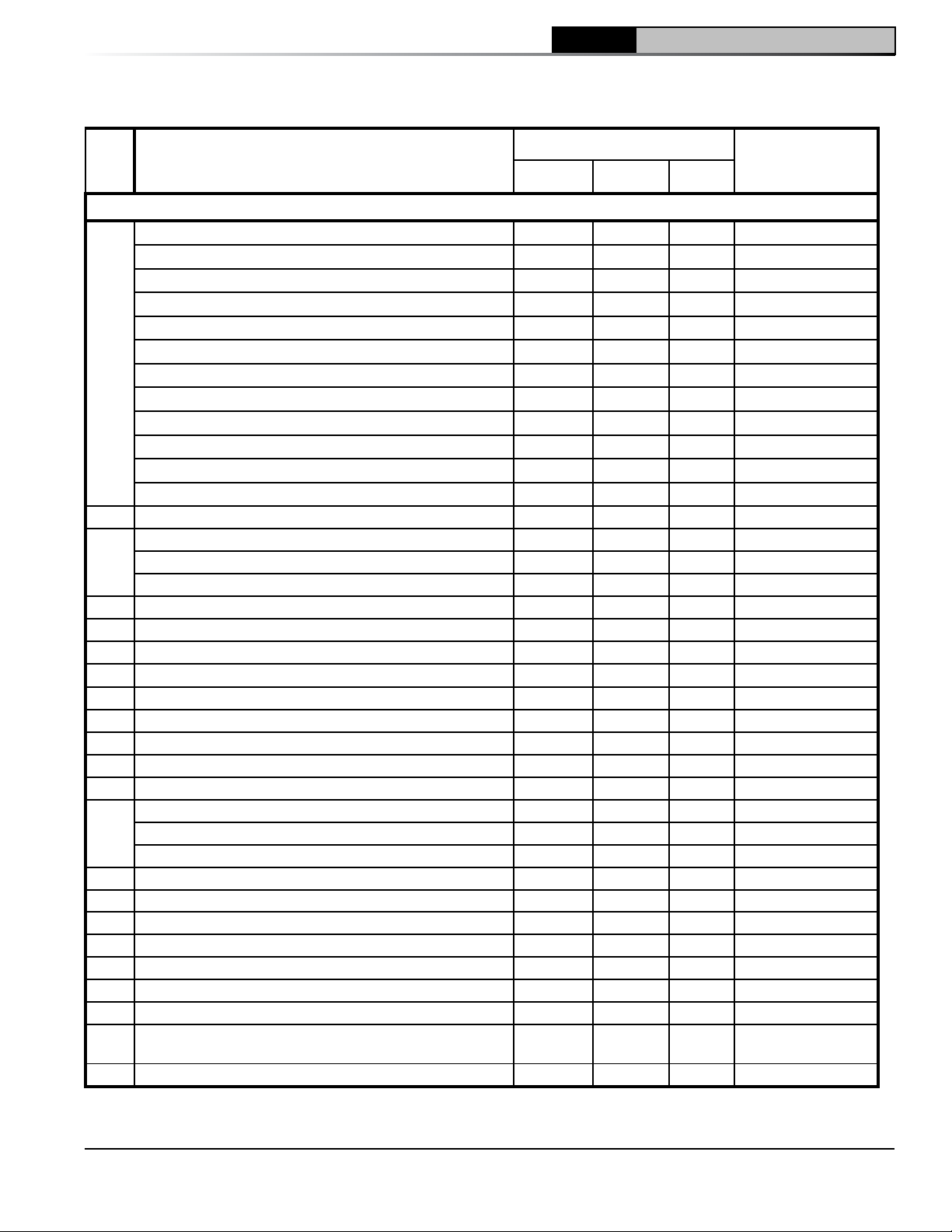
10 Repair Parts (continued)
CL
Installation & Service Manual
Item
No.
Description
Boiler Size / Quantity
Part No.
CL3 CL4 CL5
Bare Boiler Assembly
Water Replacement Block Assembly, less coil
Water Replacement Block Assembly, less coil
Water Replacement Block Assembly, less coil
Water Replacement Block Assembly, with coil
Water Replacement Block Assembly, with coil
Water Replacement Block Assembly, with coil
1
Steam Replacement Block Assembly, less coil
Steam Replacement Block Assembly, less coil
Steam Replacement Block Assembly, less coil
Steam Replacement Block Assembly, with coil
Steam Replacement Block Assembly, with coil
Steam Replacement Block Assembly, with coil
2 Rear Target Wall Insulation 1 1 1 See 108471-01
Combustion Chamber Liner, 1/2" x 19-1/2" x 9-3/4" 1 --- --- See 108471-01
3
Combustion Chamber Liner, 1/2" x 19-1/2" x 14-3/4" --- 1 --- See 108471-01
Combustion Chamber Liner, 1/2" x 19-1/2" x 19-3/4" --- --- 1 See 108471-01
4 BSD Hinge Loop Bracket 2 2 2 100795-02
5 5/16" Flat Washer - Plated 4 4 4 80860611
6 5/16-18 x 1" Lg. Cap Screw, Plated 2 2 2 80861341
7 5/16-18 x 1-1/2" Lg. Cap Screw, Plated 2 2 2 80861349
8 Burner Swing Door (only), Machined / Painted 1 1 1 100793-01
9 Burner Swing Door Insulation 1 1 1 See 108471-01
10 Observation Port Cover, Machined / Painted 1 1 1 71728004
11 5/16-18 x 3/4" Lg. Cap Screw, Plated 1 1 1 80861340
12 Canopy Sealing Strip (1/2" x 1-1/4" x 10') in Poly Bag 1 1 1 6206001
Canopy Assembly - 3 Section, 5-7/8" Dia. Collar 1 --- --- 104585-03
13
Canopy Assembly - 4 Section, 6-7/8" Dia. Collar --- 1 --- 104585-04
Canopy Assembly - 5 Section, 7-7/8" Dia. Collar --- --- 1 104585-05
14 1/4"-20 x 3" Lg. Carriage Bolt, Plated 2 2 2 80860119
15 1/4"-20 x 3-1/2" Lg. Carriage Bolt, Plated 2 2 2 100838-01
16 1/4"-20 Wing Nut - Plated 4 4 4 80860910
17 1/4" Flat Washer - Plated 4 4 4 80860603
18 Heater Cover Plate Gasket - Rear Heater 1 1 1 8036058
19 V1-2 Heater Carton (WT[R] & ST[R]) Rear Heater 1 1 1 6036031
20 5/16" Flat Washer - Plated 8 8 8 80860611
3/8"-16 x 7/8" Lg. Cap Screw, ASME Grade, Marked
21
SA307B
Combustion Chamber Insulation Kit 1 1 1 108471-01
1 --- --- CL3-WN
--- 1 --- CL4-WN
--- --- 1 CL5-WN
1 --- --- CL3-WR
--- 1 --- CL4-WR
--- --- 1 CL5-WR
1 --- --- 61720307
--- 1 --- 61720407
--- --- 1 61720507
1 --- --- 61720306
--- 1 --- 61720406
--- --- 1 61720506
8 8 8 80861337
103876-08 - 1/19
55
Page 56
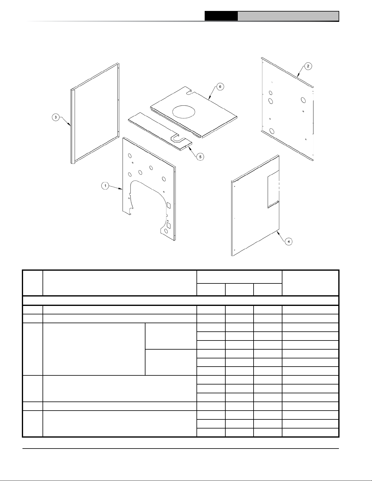
10 Repair Parts (continued)
CL Installation & Service Manual
Jacket Assembly (Exploded View)
Item
No.
Description
Boiler Size / Quantity
Part No.
CL3 CL4 CL5
Jacket Components -- Items 1 thru 6 Include Insulation as Part of Assembly
1 Jacket Front Panel Assembly 1 1 1 100819-01
2 Jacket Rear Panel Assembly 1 1 1 100820-01
2 --- --- 100821-03
Non-Heater Build
3 Jacket Reversible Side Panel Assembly
With Heater Build
Jacket Left Side Heater Panel Assembly
4
(WT[R] & ST[R]) Heater Builds)
5 Jacket Split Front Top Panel Assembly 1 1 1 100823-01
6 Jacket Split Rear Top Panel Assembly
--- 2 --- 100821-04
--- --- 2 100821-05
1 --- --- 100821-03
--- 1 --- 100821-04
--- --- 1 100821-05
1 --- --- 100824-03
--- 1 --- 100824-04
--- --- 1 100824-05
1 --- --- 100822-03
--- 1 --- 100822-04
--- --- 1 100822-05
56
103876-08 - 1/19
Page 57
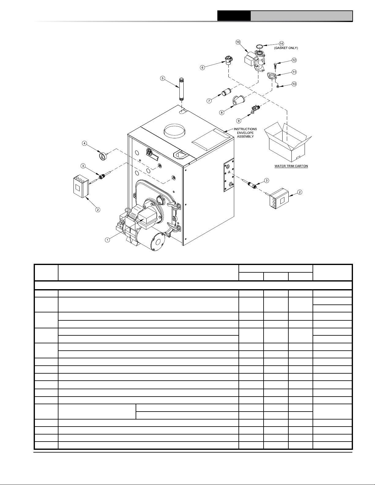
10 Repair Parts (continued)
CL
Installation & Service Manual
CL3 Thru CL5 Water Boilers - Trim and Controls
Item
No.
Description
CL3 Thru CL5 Water Boilers - Trim and Controls
1 Beckett GeniSys 7505B Oil Primary Control 1 1 1 103447-01
Honeywell L7248L1090 Hi Limit, Circ. Relay (WN)
2a
Honeywell L7224C1010 Hi & Lo Limit, Circ. Relay (WT)
Hydrolevel HydroStat 48-3257 Boiler control (WN)
2b
Hydrolevel HydroStat 48-3257TCE Boiler Control (WT)
1/2" NPT x 1-1/2" Immersion Well, Honeywell 123869A (WN)
3a
3/4" NPT x 3" Immersion Well, Honeywell 123871A (WT) 80160452
1/2" NPT x 1" Electro-Well, Hydrolevel 48-221 (WN)
3b
3/4" NPT x 4" Electro-Well, Hydrolevel 48-206 (WT)
4 Temperature / Pressure Gauge, ¼" NPT x 2-1/2" Dia. x 1-1/2" Lg. Shank 1 1 1 100282-01
5 3/4" NPT x 7-1/4" Lg. Nipple, SCH 80, Black 1 1 1 100839-01
6 Relief Valve, 3/4" F x 3/4" F, 30 PSI, #10-408-05 1 1 1 81660319
7 1-1/2" NPT x 5" Lg. Nipple, Black 1 1 1 806600060
8 1-1/2" x 3/4" x 1-1/2" NPT Tee, Black 1 1 1 806601003
9 3/4" NPT Ball Drain Valve, Conbraco #35-302-03 1 1 1 806603061
10 Circulator w/Gaskets
11 Circulator Flange, 1-1/2" NPT 2 2 2 806602014
12 Cap Screw, Hex Head, 7/16" -14 x 1-1/2" Lg. 4 4 4 80861301
13 Hex Nut, 7/16" -14 4 4 4 80860406
14 Taco "00" Series Flange Gasket (Gasket Only) 2 2 2 806602006
Taco 007e 1 1 1 Supplied
Grundfos ALPHA 2 1 1 1
Boiler Size / Quantity
CL3 CL4 CL5
1 1 1
1 1 1
1 1 1
1 1 1
1 1 1
1 1 1
Part No.
103850-01
103854-01
104579-01
106967-01
80160456
104098-01
105310-01
Locally
103876-08 - 1/19
57
Page 58
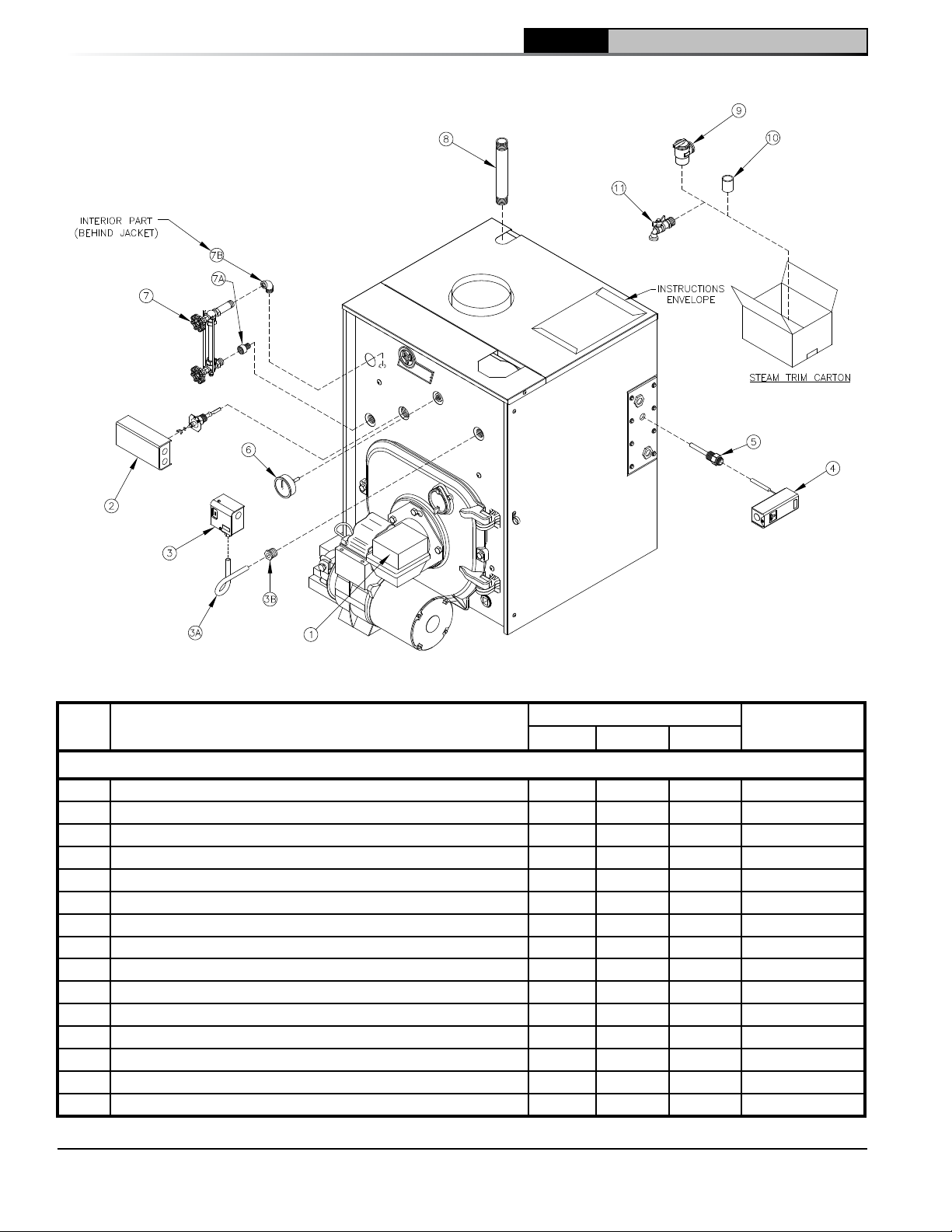
10 Repair Parts (continued)
CL Installation & Service Manual
CL3 Thru CL5 Steam Boilers - Trim and Controls
Item
Description
No.
CL3 Thru CL5 Steam Boilers - Trim and Controls
1 Beckett GeniSys 7505B Oil Primary Control 1 1 1 103447-01
2 McDonnell & Miller PSE801-120 LWCO With Probe 1 1 1 80160723
3 Honeywell PA404A1009 Pressuretrol 1 1 1 80160300
3A 1/4" x 90° Syphon, 1-7/8"" Equal Leg 1 1 1 806603014
3B 1/2" x 1/4" NPT Bushing, Black / Steel 1 1 1 806600524
4 Honeywell L4006A2015 Aquastat 1 1 1 80160400
5 3/4" NPT x 3" Immersion Well, Honeywell #123871A 1 1 1 80160452
6 Steam Gauge, 1/4" NPT x 2-1/2" Dia. x 7/8" Shank 1 1 1 100325-01
7 10¼" Gauge Glass Set, Conbraco #22-171-10 1 1 1 100854-01
7A 1/2" Male x ½" Female NPT Brass Extension Piece 1 1 1 100853-01
7B 1/2" NPT Brass Street Elbow 1 1 1 100852-01
8 3/4" NPT x 7¼" Lg. Nipple, SCH 80, Black 1 1 1 100839-01
9 3/4" NPT, M/F, 15 PSI Safety Valve Conbraco #13-511-B15 1 1 1 81660530
10 3/4" NPT Coupling, Malleable 1 1 1 806602561
11 3/4" NPT Ball Drain Valve, Conbraco #35-302-03 1 1 1 806603061
Boiler Size / Quantity
CL3 CL4 CL5
Part No.
58
103876-08 - 1/19
Page 59
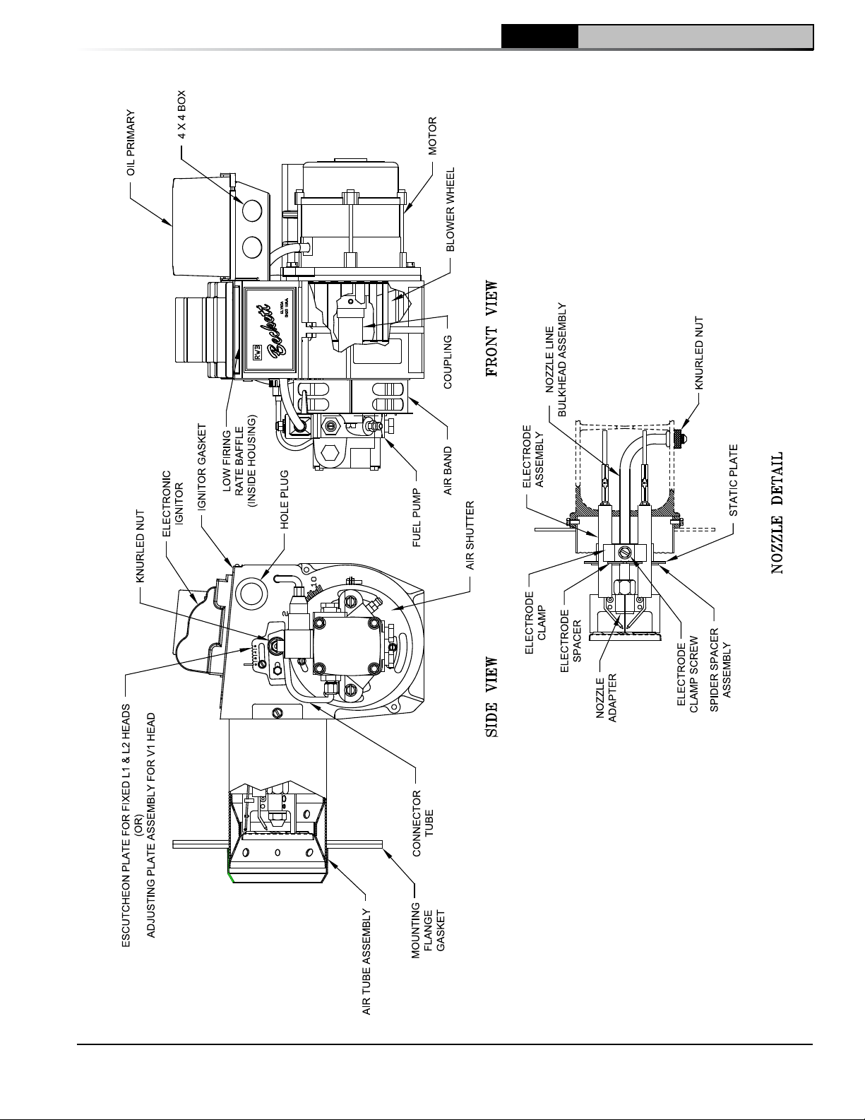
10 Repair Parts (continued)
CL
Installation & Service Manual
Beckett AFG Burner
103876-08 - 1/19
59
Page 60
CL Installation & Service Manual
10 Repair Parts (continued)
BECKETT AFG OIL BURNER PART NOS. FOR CL SERIES BOILERS
NOTE: When ordering parts always give the serial and model numbers shown on the boiler and burner. Also
provide the name of the part(s) and part number as listed below.
Boiler Model CL3-091, 105, 140 CL4-126 CL4-175, 210 CL5-168, 245, 280
Air Tube Combination AFG70MMAQ AFG70MMAQ AFG70MDAQ AFG70MLAQ
Beckett's Spec No. NY2710 NY2711 NY2712 NY2713
Air Band 3492A 3492A 3492A 3492A
Air Band Nut 4150 4150 4150 4150
Air Band Screw 4198 4198 4198 4198
Air Shutter 3709 3709 3709 3709
Air Shutter Screw 4198 4198 4198 4198
Blower Wheel 2999 2999 2999 2999
Coupling 2454 2454 2454 2454
Low Firing Rate Baffle 5880[1] ---- ---- ----
Bulkhead Knurled Locknut 3-666 3-666 3-666 3-666
Connector Tube Assembly 5636 5636 5636 5636
Electrode Clamp 1-49 1-49 1-49 1-49
Electrode Clamp Screw 4219 4219 4219 4219
Electrode Insulator Assembly 5780 5780 5780 5780
Spider Spacer Assembly 5653 5653 5653 5653
Escutcheon Plate 3493 3493 ---- ----
Adjusting Plate Assembly ---- ---- 5941 5941
Head 5912 5912 5913 5913
Head Screws 4221 4221 4221 4221
Flange Gasket 3416 3416 3416 3416
AFG Housing 5874BK 5874BK 5874BK 5874BK
Motor 21805 21805 21805 21805
Nozzle Adapter 2-13 2-13 2-13 2-13
Nozzle Line Electrode Assembly NL70MM NL70MM NL70MD NL70ML
Oil Pump, Clean Cut
(Single Stage)
Oil Pump, Clean Cut
(Two Stage)
Static Plate 3384 3384 3383 Less
Ignitor 51771U 51771U 51771U 51771U
Ignitor Hinge Screw 4217 4217 4217 4217
Ignitor Holding Screw 4292 4292 4292 4292
Ignitor Gasket Kit 51304 51304 51304 51304
Junction Box 5770 5770 5770 5770
Flame Detector 7006 7006 7006 7006
Oil Solenoid Valve Coil 21755 21755 21755 21755
Oil Solenoid Valve Cord 21807 21807 21807 21807
[1] 5880 used on CL3-091 firing rate only
2184404U 2184404U 2184404U 2184404U
21941U 21941U 21941U 21941U
60
103876-08 - 1/19
Page 61
11 Burner Specifications
Table 14A: Beckett Afg Burner Specifications
Beckett AFG
CL
Installation & Service Manual
Boiler Series
1
CL3-091
p CL3-140
CL4-126 0.90 L1 7 0 0.75 x 60B Installed 140
CL4-175 1.25
CL4-210
CL5-168 1.20 V1(0) 8 1 0.90 x 60B (Hago)
CL5-280
1
Beckett low firing rate baffle required on CL3-091 (0.65 GPH) application only; shipped loose with nozzle.
2
Nozzle(s) for alternate boiler series firing rate(s) are shipped loose in bag attached to the burner designated by
corresponding symbol, i.e. (p) = CL3-140.
3
Single stage fuel pump is standard, two stage fuel pump is optional. Burner manufacturer has preset
single stage fuel pump to settings shown in table above.
4
All burners utilize Delavan nozzle unless otherwise specified.
Firing Rate
GPH
0.65
1.00 5 2 0.85 x 60B (Hago) Installed
1.50 10 6 1.25 x 60B (Hago) Installed
2.00 V1(4) 8 4 1.50 x 45B (Hago) Installed
Head
(Setting)
L1
V1(0)
Settings Nozzle
Air
Shutter
8 0 0.55 x 70B
10 0.5 1.00 x 60B (Hago)
Air
Band
GPH x Angle Type
4
2
Shipped
p Loose
p Loose
Loose
Loose
Loose
3
Pump
Pressure
140CL3-105 0.75 10 2 0.65 x 60B (Hago)
140
175CL5-245 1.75 V1(3) 6 6 1.35 x 45B (Hago)
103876-08 - 1/19
61
Page 62
CL Installation & Service Manual
11 Burner Specifications (continued)
RIELLO 40 SERIES OIL BURNER PART NUMBERS FOR CL SERIES BOILERS
Table 14B: Riello Burner Specifications
Boiler
Series
CL3-105 0.75
CL3-140 1.00 2.85 2 0.85 x 60W Loose
CL4-126 0.90 40F5 2.25 0 0.75 x 60B Installed 150
CL4-175 1.25 40F5 4 4 1.00 x 60A Installed 150
CL4-210 1.50 40F5 3 1 1.25 x 60B Installed 150
CL5-168 1.20 40F5 2.9 0 1.00 x 80B Installed 150
CL5-245 1.75
CL5-280
2
Nozzle(s) for alternate boiler series firing rate(s) are shipped loose in bag attached to the
Firing
Rate
GPM
2.00 3.8 2 1.65 x 45B Installed
Burner
Model
40F5
40F10
Settings Nozzle
4
2
Air Gate Turbulator GPH x Angle Type
2.60 0 0.60 x 60A Installed
3 1.5 1.35 x 45B
Shipped
Loose
Pump
Pressure
150
150
burner designated by corresponding symbol, i..e. () = CL5-280.
4
All burners utilize Delavan nozzle unless otherwise specified.
NOTE: When ordering parts always give the serial and model numbers shown on the boiler and burner.
Refer to Models F3 & F5 Installation Manual, Riello 40 Series Residential Oil Burners (C6501010) or Model F10
Installation Manual, Riello 40 Series Residential Oil Burners (2902554) for an exploded view of the burner and a
list of spare parts.
For replacement Riello oil burner parts, contact your wholesaler or the burner manufacturer:
Riello Corporation of America
35 Pond Park Road
Hingham, Massachusetts 02043
Telephone: (781) 749-8292
Toll Free: (outside Massachusetts)
(800) 474-3556
62
Riello Canada Inc.
2165 Meadowpine Blvd.
Mississauga, Ontario L5N 6H6
Telephone: (905) 542-0303
Facsimile: (905) 542-1525
Toll Free: (800) 387-3898
103876-08 - 1/19
Page 63
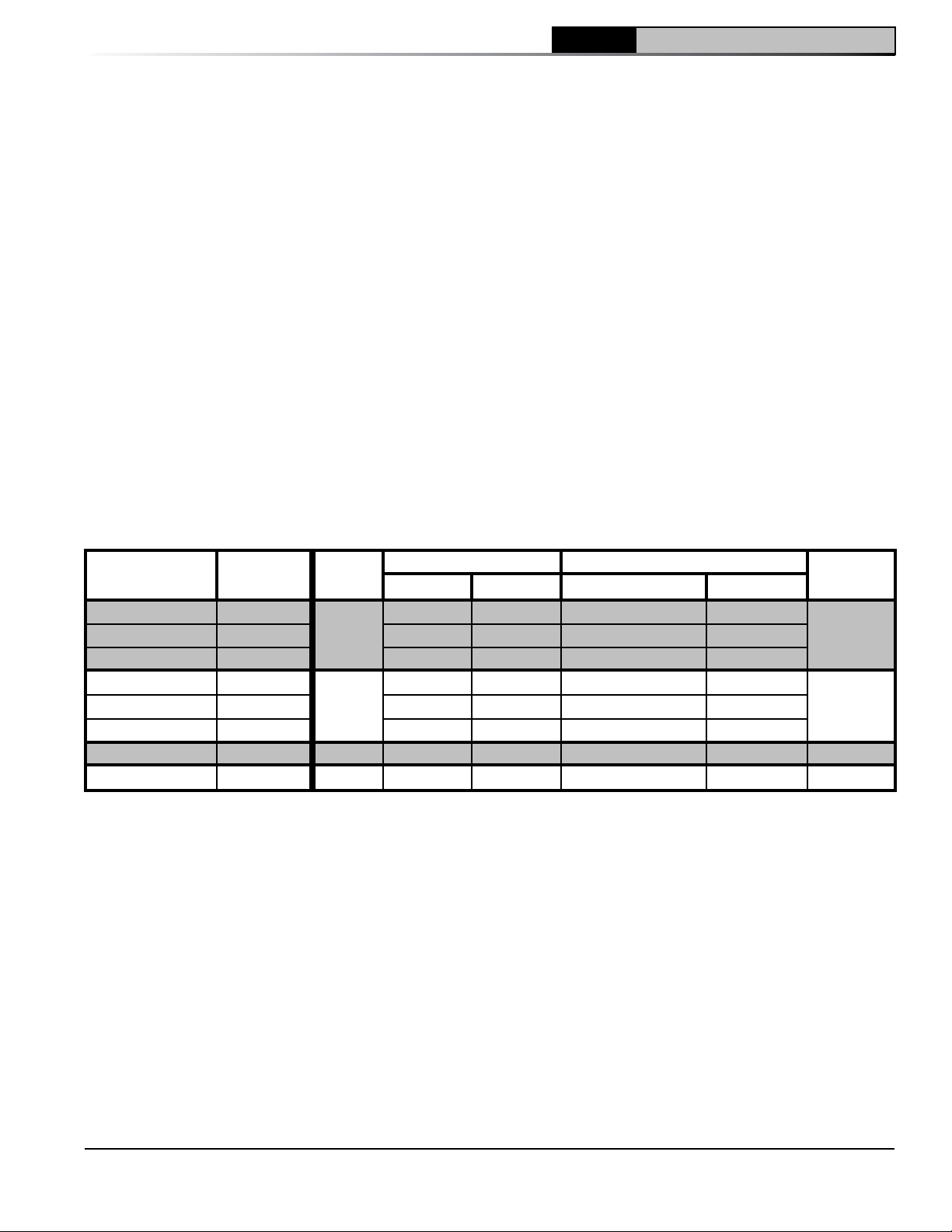
CL
Installation & Service Manual
11 Burner Specifications (continued)
CARLIN OIL BURNER PART NUMBERS FOR CL SERIES BOILERS
NOTE: When ordering parts always give the serial and model numbers shown on the boiler and burner.
Refer to Carlin Model EZ-1/2/3 Oil Burner-Instruction Manual (Form #MNEZ123) for an exploded view of the
burner and a list of spare parts.
For replacement Carlin oil burner parts, contact your wholesaler or the burner manufacturer:
CCT, Carlin Combustion Technology, Inc.
126 Bailey Road
North Haven, CT 06475
Telephone: (203) 680-9401
Table 14C: Carlin EZ-1HP and EZ-2HP Burner Specifications
Boiler
Series
CL3-091 0.65
CL3-105 0.75 0.60/0.65 0.60 0.60 x 60A
p CL3-140
CL4-126 0.90
CL4-175 1.25 0.85/1.00 1.00-1.10 1.00 x 60A
CL4-210
CL5-168 1.20 0.85/1.00 0.90 1.00 x 60B Installed 150
CL5-245 1.75 EZ-2HP 1.50 1.75 1.50 x 60A Installed 150
2
Nozzle(s) and Head Positioning Bar Kit for alternate boiler series firing rate(s) are shipped loose in bag attached to the
burner designated by corresponding symbol, i.e. (
3
Single stage fuel pump is standard, two stage fuel pump is optional. Burner manufacturer has preset single stage fuel
pump to settings shown in table above.
4
All burners utilize Delavan nozzle unless otherwise specified.
Firing Rate
GPH
1.00 0.85/1.00 0.75 0.85 x 60B Installed
1.50 1.10/1.25 1.25-1.35 1.25 x 60B Installed
Burner
Model
EZ-1HP
EZ-1HP
Settings Nozzle
Head Bar Air Band GPH x Angle Type
0.50 0.55 0.55 x 70B
0.75 0.75 0.75 x 60A
4 2
p Loose
p Loose
Loose
Loose
p) = CL3-140.
Shipped
Pressure
3
Pump
150
150
103876-08 - 1/19
63
Page 64
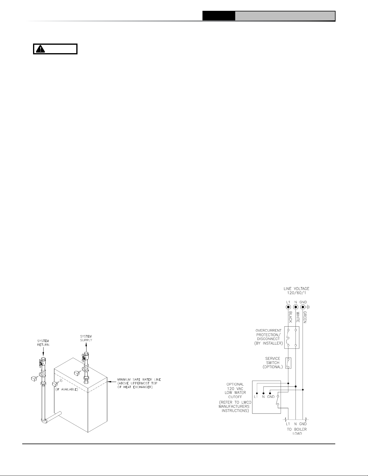
CL Installation & Service Manual
Appendix A Aftermarket Low Water Cut Off (LWCO)
WARNING
(LWCO). Only use connections specifically identified for Low Water Cut Off.
In all cases, follow the Low Water Cut Off (LWCO) manufacturer's instructions.
DO NOT ATTEMPT to cut factory wires to install an aftermarket Low Water Cut Off
When
A low water cutoff is required to protect a hot
water boiler when any connected heat distributor
(radiation) is installed below the top of the hot
water boiler (i.e. baseboard on the same floor
level as the boiler). In addition, some jurisdictions
require the use of a LWCO with a hot water boiler.
Where
The universal location for a LWCO on oil hot water
boilers is above the boiler, in either the supply or
return piping. The minimum safe water level of a
water boiler is at the uppermost top of the boiler;
that is, it must be full of water to operate safely.
It is recommended that the LWCO control
is installed above the boiler to provide the
highest level of protection. However, where
the LWCO control is approved by the LWCO
control manufacturer for installation in a high
boiler tapping of a water boiler, the use of the
listed LWCO control is permitted when it is
installed according to the LWCO manufacturer’s
instructions
What Kind
Typically, in residential applications, a probe type
LWCO is used instead of a float type, due to their
relative costs and the simplicity of piping for a
probe LWCO.
Select the appropriate size tee using the LWCO
manufacturer’s instructions. Often, the branch
connection must have a minimum diameter to
prevent bridging between the probe and the tee.
Also, the run of the tee must have a minimum
diameter to prevent the end of the probe from
touching or being located too close to the inside
wall of the run of the tee.
Ideally, manual shutoff valves should be located
above the LWCO and the boiler to allow for
servicing. This will allow probe removal for
inspection without draining the heating system.
Many probe LWCO manufacturers recommend an
annual inspection of the probe.
How to Wire
LWCO’s are available in either 120 VAC or 24
VAC configurations. The 120 VAC configuration
must be applied to oil boilers by wiring it in the
line voltage service to the boiler (after the service
switch, if so equipped). Refer to Figure A2.
The presence of water in a properly installed
LWCO will cause the normally open contact of the
LWCO to close, thus providing continuity of the
120 VAC service to the boiler.
It is recommended to supply power to the probe
LWCO with the same line voltage servicing the
boiler as shown below.
How to Pipe
A “tee” is commonly used to connect the probe
LWCO in the supply or return piping, as shown
below.
Figure A1: LWCO Location
64
Figure A2: Wiring of Typical LWCO
103876-08 - 1/19
Page 65

CL
Installation & Service Manual
Appendix A Aftermarket Low Water Cut Off (LWCO) (continued)
How to Test
Shut off fuel supply. Close shut-off valves in
system supply and return piping located in near
boiler piping above LWCO as shown in Figure
A1. Open drain valve to lower water level until
water is below the LWCO probe. It may be
necessary to open relief valve seat to allow air
into system for the water to drain, close drain
valve and relief valve once completed. Generate
a boiler demand by turning up thermostat. Boiler
should not attempt to operate. Open fill valve to
increase the water level by filling the system. It
may be necessary to open relief valve to allow air
to escape during filling process. The boiler should
attempt to operate once the water level is above
the LWCO.
103876-08 - 1/19
65
Page 66
CL Installation & Service Manual
66
103876-08 - 1/19
Page 67
CL
Installation & Service Manual
103876-08 - 1/19
67
Page 68

CL Installation & Service Manual
68
103876-08 - 1/19
 Loading...