

Page 1
INSTALLATION, OPERATING
AND
SERVICE INSTRUCTIONS
CG-E™ SERIES
GAS BOILER
9700609
BEFORE INSTALLATION: READ THIS MANUAL
SAVE THESE INSTRUCTIONS
Installing contractor and homeowner should read and be informed as to the proper installation and operation of this boiler.
The manufacturer will not be responsible for improper installation or operation. This manual and all associated instruction
material should be conspicuously posted near the boiler.
For service or repairs to boiler, call your heating contractor. When seeking information on boiler,
provide Boiler Model Number and Serial Number as shown on Rating Label.
Boiler Model Number
CG _ _ E
Heating Contractor Phone Number
Address
Boiler Serial Number Installation Date
106213-01- 11/15
Price - $5.00
Page 2
The City of New York requires a Licensed Master Plumber supervise the installation of this product.
The Massachusetts Board of Plumbers and Gas Fitters has approved the CG-E™ Series Boiler. See the Massachusetts Board of
Plumbers and Gas Fitters website, http://license.reg.state.ma.us/pubLic/pl_products/pb_pre_form.asp for the latest Approval
Code or ask your local Sales Representative.
The Commonwealth of Massachusetts requires this product to be installed by a licensed Plumber or Gas tter.
The following terms are used throughout this manual to bring attention to the presence of hazards of various
risk levels, or to important information concerning product life.
DANGER
Indicates an imminently hazardous situation
which, if not avoided, will result in death, serious
injury or substantial property damage.
WARNING
Indicates a potentially hazardous situation which,
if not avoided, could result in death, serious injury
or substantial property damage.
Table of Contents
CAUTION
Indicates a potentially hazardous situation which,
if not avoided, may result in moderate or minor
injury or property damage.
NOTICE
Indicates special instructions on installation,
operation, or maintenance which are important
but not related to personal injury hazards.
I. Pre-Installation ....................................5
II. Unpack Boiler .....................................5
III. Water Piping and Trim ........................6
IV. Venting .............................................. 10
V. Gas Piping .........................................12
VI. Electrical ............................................13
2
VII. System Start-up and Checkout ..................... 17
VIII. Operation ..........................................20
IX. Service and Maintenance ...................22
X. Troubleshooting ................................24
XI. Repair Parts .......................................29
Warranty .............................Back Cover
Page 3
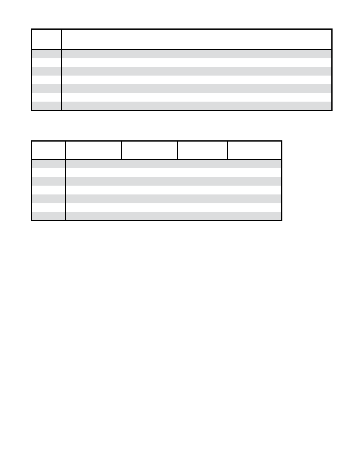
Table 1A: Dimensions and Connections
Boiler
Model
CG30E 32 14 40 1¼ 1¼ 4 ½ ¾ ¾
CG40E 32 16 40 1¼ 1¼ 5 ½ ¾ ¾
CG50E 32 19 40 1¼ 1¼ 6 ½ ¾ ¾
CG60E 32 22 40 1¼ 1¼ 6 ½ ¾ ¾
CG70E 32 25 40 1¼ 1¼ 7 ¾ ¾ ¾
CG80E 32 28 40 1¼ 1¼ 7 ¾ ¾ ¾
CG90E 32 31 40 1¼ 1¼ 8 ¾ ¾ ¾
Depth Width Height
Supply NPT
(inch)
Return NPT
(inch)
Vent
(inch)
Gas NPT
(inch)
Relief Valve
NPT (inch)
Drain
NPT (inch)
Table 1B: Inputs, Weights and Volumes
Boiler
Model
CG30E 70 254 180 2
CG40E 105 304 231 3
CG50E 140 357 284 4
CG60E 175 405 332 5
CG70E 210 462 382 6
CG80E 245 518 438 7
CG90E 280 564 484 8
(1)
Input ratings can be used for elevations up to 2000 ft. Refer to System Start-up and Checkout Sections for elevations 2000 ft.
or higher.
Input (MBH)
(1)
Shipping Weight
(lbs)
Empty Weight
(lbs)
Water Content
(gal)
Electrical Requirements: 120VAC, 60 Hz, 1-ph, Less than 12A
Maximum Allowable Working Pressure - 50 psi. Boiler shipped from factory with a 30 psi relief valve.
3
Page 4
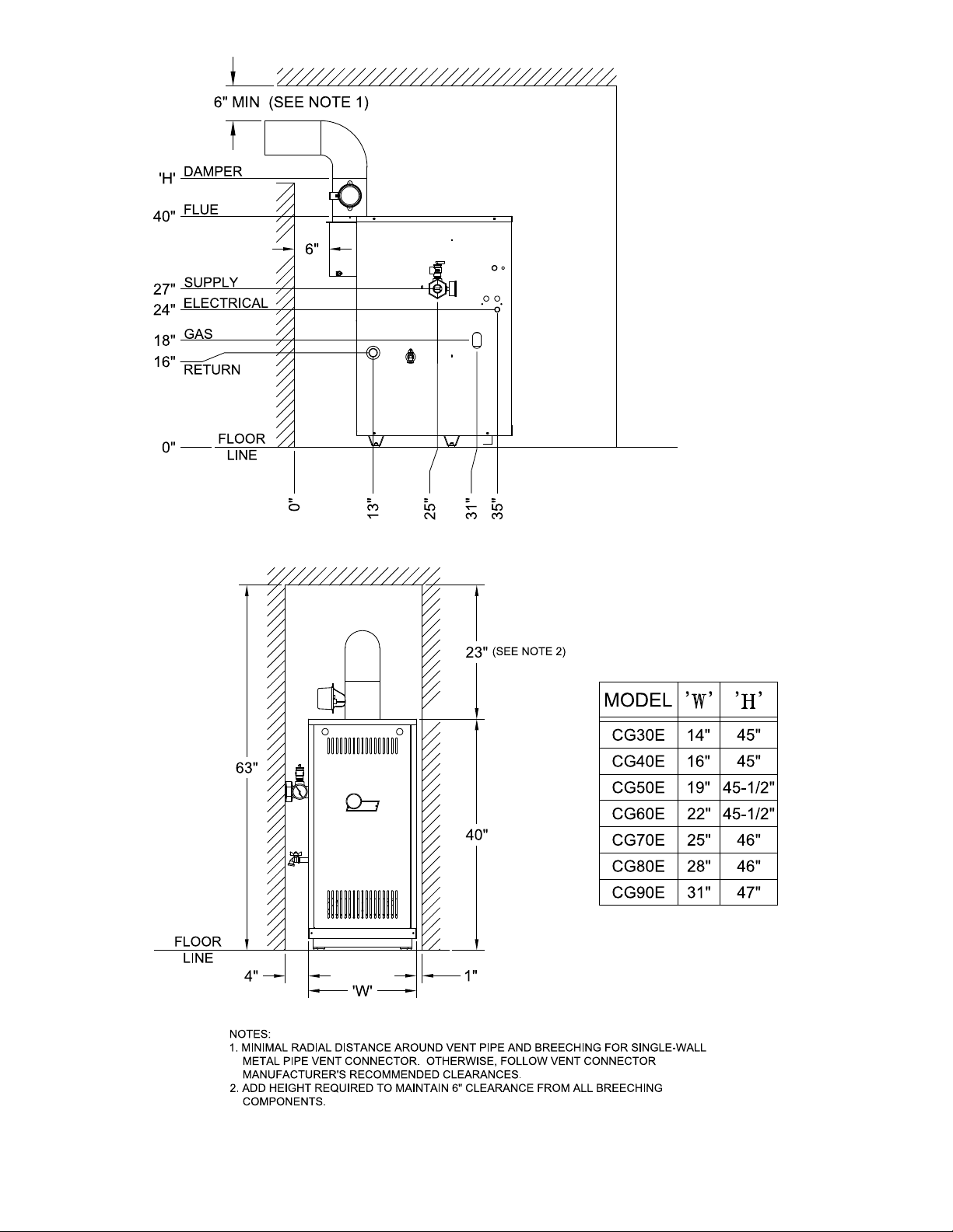
Figure 1: Minimum Clearance to Combustible Materials and Alcove Dimensions
4
Page 5
I. Pre-Installation
WARNING
Carefully read all instructions before installing
boiler. Failure to follow all instructions in proper
order can cause personal injury or death.
A. Inspect shipment carefully for any signs of damage.
All equipment is carefully manufactured, inspected
and packed. Our responsibility ceases upon delivery
of boiler to carrier in good condition. Any claim
for damage or shortage in shipment must be led
immediately against carrier by consignee. No claims
for variances or shortages will be allowed by Boiler
Manufacturer, unless presented within sixty (60) days
after receipt of equipment.
B. Installation must conform to the requirements of the
authority having jurisdiction. In the absence of such
requirements, installation must conform to National
Fuel Gas Code, ANSI Z223.1/NFPA 54.
C. Appliance is design certied for installation on
combustible ooring. The boiler must not be installed
on carpeting.
D. Provide clearance between boiler jacket and
combustible material in accordance with local re
ordinance. Refer to Figure 1 for minimum clearance
from combustible material for alcove installation.
Provide 1/2" clearance from water piping to
combustible materials.
F. Install on level oor. For basement installation provide
concrete base if oor is not level or if water may be
encountered on oor around boiler.
CAUTION
ASSURE THAT THE FRONT AIR DAM is in place
and undamaged. A damaged front air dam will
negatively affect the performance of this boiler,
which can cause serious property damage,
personal injury or death.
G. Protect gas ignition system components from water
(dripping, spraying, rain, etc.) during boiler operation
and service (circulator replacement, condensate trap,
control replacement, etc.).
H. Provide combustion and ventilation air in accordance
with the section "Air for Combustion and Ventilation,"
of the National Fuel Gas Code, ANSI Z223.1/NFPA 54,
or applicable provisions of local building codes.
WARNING
Adequate combustion and ventilation air must be
provided to assure proper combustion.
I. Do not install boiler where gasoline or other
ammable vapors or liquids, or sources of
hydrocarbons (i.e. bleaches, cleaners, chemicals, sprays,
paint removers, fabric softeners, etc.) are used or stored.
E. Provide practical service clearances. A minimum
of 24" from the left side and front jacket panels is
recommended for servicing but may be reduced to
minimums shown in Figure 1.
II. Unpack Boiler
CAUTION
Do not drop boiler. Do not bump boiler jacket
against oor.
A. Move boiler to approximate installed position.
B. Remove all crate fasteners.
C. Lift outside container and remove with all other
inside protective spacers and bracing. Save two of the
wooden slats from the container sleeve for use in Steps
E and F.
D. Remove all boiler hold-down fasteners.
E. Tilt the boiler to one side and slide a wooden slat under
the two raised feet.
F. Tilt the boiler to the other side and slide another
wooden slat under the two raised feet.
G. Slide the boiler forward or backward off the skid using
the two wooden slats as runners.
H. Move boiler to its permanent location.
5
Page 6
III. Water Piping and Trim
WARNING
Failure to properly pipe boiler may result in
improper operation and damage to boiler or
building.
A. Design and install boiler and system piping to
prevent oxygen contamination of boiler water.
Oxygen contamination sources are system leaks
requiring addition of makeup water, ttings, and
oxygen permeable materials in distribution system.
Eliminate oxygen contamination by repairing system
leaks, repairing ttings, and using non-permeable
materials in distribution system.
B. Install circulator with anges, gaskets and bolts
provided.
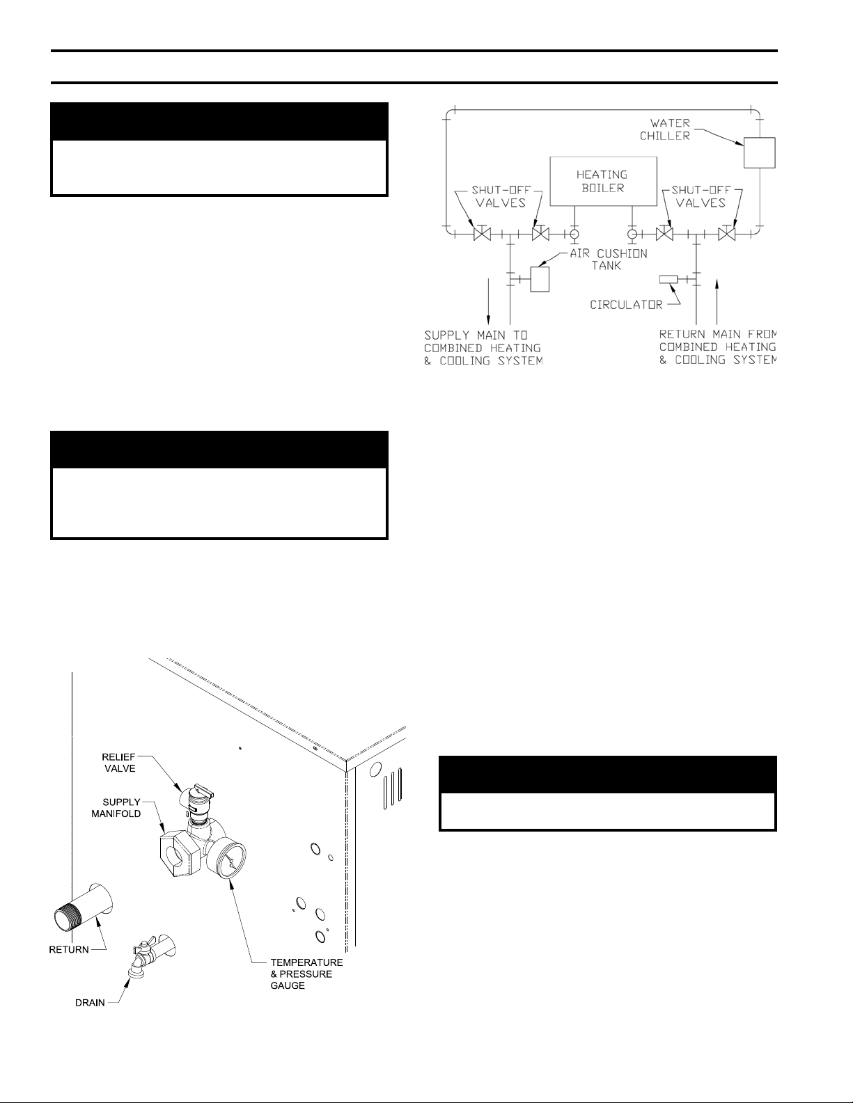
C. Install Safety Relief Valve. See Figure 2. Safety Relief
Valve must be installed with spindle in vertical position.
WARNING
Safety relief valve discharge piping must be piped
near oor to eliminate potential of severe burns.
Do not pipe in any area where freezing could
occur. Do not install any shut-off valves.
D. Connect system supply and return piping to boiler.
Refer to Figures 2, 5 and 6. Also consult Residential
Hydronic Heating Installation and Design I=B=R
Guide. Maintain minimum ½ inch clearance from hot
water piping to combustible materials.
Figure 3: Recommended Piping for Combination
Heating & Cooling (Refrigeration) Systems
E. If boiler is used in connection with refrigeration
systems, boiler must be installed with chilled medium
piped in parallel with the heating boiler using
appropriate valves to prevent chilled medium from
entering boiler. See Figure 3. Also consult Residential
Hydronic Heating Installation and Design I=B=R
Guide.
F. If boiler is connected to heating coils located in
air handling units where they may be exposed to
refrigerated air, boiler piping must be equipped with
ow control valves or other automatic means to prevent
gravity circulation of boiler water during operation of
cooling system.
G. Use a boiler bypass if the boiler is to be operated
in a system which has a large volume or excessive
radiation where low boiler water temperatures may be
encountered (i.e. converted gravity circulation system,
etc.).
CAUTION
Boiler return water cannot be lower than 130°F for
proper function.
Install bypass between boiler supply and return in near
boiler piping as shown in Figures 5 and 6. Bypass
should be same size as the supply and return lines with
valves located in bypass and supply outlet as illustrated
in Figures 5 and 6 in order to regulate water ow to
maintain higher boiler water temperatures.
Set by-pass and boiler supply valves to half throttle
position to start. Operate boiler until system water
temperature reaches normal operating range.
Figure 2: Near Boiler Piping
6
Page 7
Adjust valves to provide 180° to 200°F supply water
temperature. Opening the boiler supply valve will raise
system temperature, while opening by-pass valve will
lower system supply temperature.
H. If it is required to perform a long term pressure
test of the hydronic system, the boiler should rst be
isolated to avoid a pressure loss due to the escape of air
trapped in the boiler.
To perform a long term pressure test including the
boiler, ALL trapped air must rst be removed from the
boiler.
A loss of pressure during such a test, with no visible
water leakage, is an indication that the boiler contained
trapped air.
I. Optional LWCO Installation
WARNING
DO NOT ATTEMPT to cut factory wires to
install an aftermarket Low Water Cut Off
(LWCO). Only use connections specically
identied for Low Water Cut Off.
In all cases, follow the Low Water Cut Off
(LWCO) manufacturer’s instructions.
1. A low water cutoff is required to protect a gas-red
hot water boiler when any connected heat distributor
(radiation) is installed below the top of the hot water
boiler (i.e. baseboard on the same oor level as
the boiler). In addition, some jurisdictions require
the use of a LWCO with a hot water boiler as a
redundant safety control.
It is recommended that the LWCO control is
installed above the boiler to provide the highest
level of protection. However, where the LWCO
control is approved by the LWCO control
manufacturer for installation in a high boiler tapping
of a water boiler, the use of the listed LWCO control
is permitted when it is installed according to the
LWCO manufacturer's instructions.
2. The recommended location for a LWCO on gas
hot water boilers is above the boiler, in the supply
piping. The minimum safe water level of a water
boiler is at the uppermost top of the boiler; that is, it
must be full of water to operate safely.
3. Typically, in residential applications, a probe type
LWCO is used instead of a oat type, due to their
relative costs and the simplicity of piping for a
probe LWCO.
4. Piping and ttings required to install LWCO are
eld supplied.
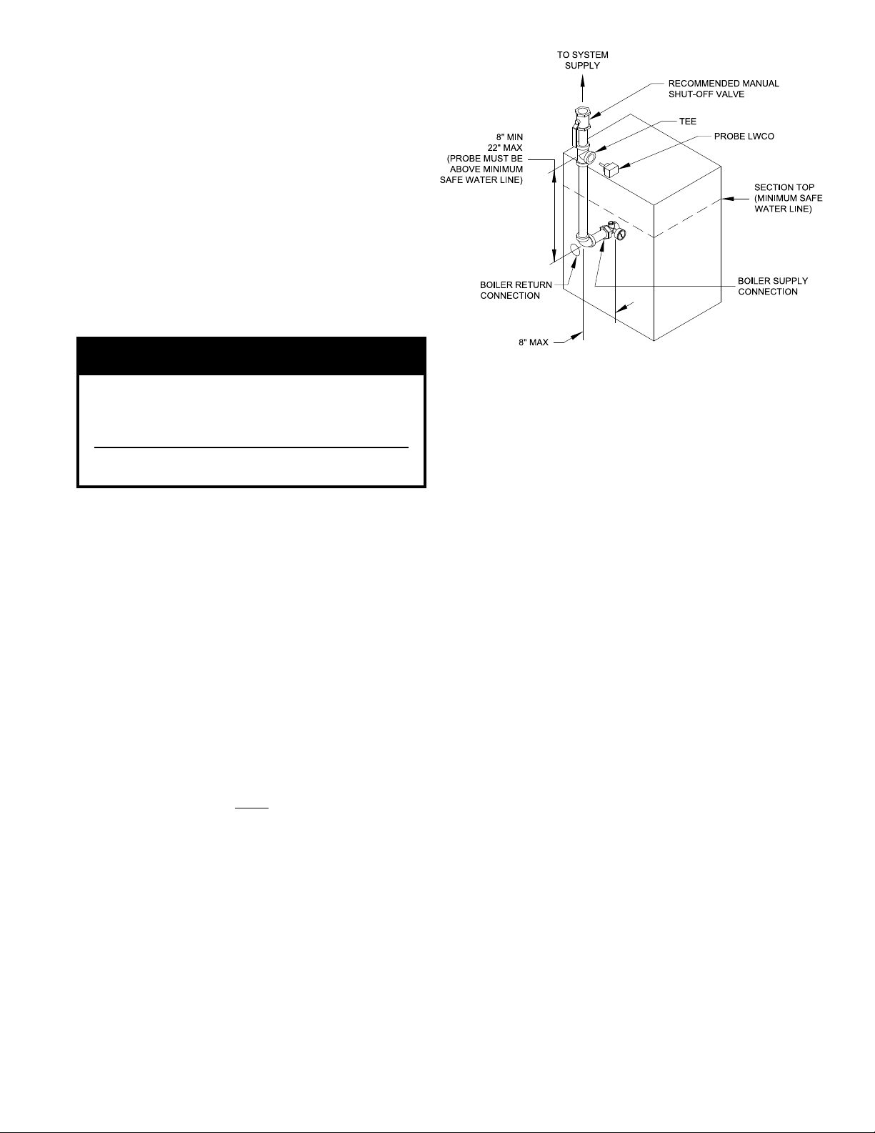
Figure 4: Recommended Probe LWCO Location
5. When constructing a piping tree to install LWCO
select ttings (tees, elbows etc) and nipples to have
the same size (NPT) as boiler supply connection.
At minimum, 1-1/4” tee with ¾” branch outlet is
required to connect the probe LWCO to the supply
piping. See Figure 4. DO NOT REDUCE THE
SIZE OF NEAR BOILER SUPPLY FITTINGS
AND NIPPLES.
6. Installation of manual shutoff valve located above
the LWCO and the boiler is recommended to allow
servicing. Thus LWCO probe can be removed for
inspection without draining the heating system. An
annual inspection of the probe is recommended.
7. The presence of water covering properly installed
LWCO probe will cause the normally open contact
of the LWCO to close, thus providing continuity of
the 24 VAC service to the boiler gas valve. When
water level drops below probe, LWCO contact opens
up breaking 24V supply to gas valve and preventing
the boiler to re.
8. CG-E Series gas hot water boilers have a “plugin” provision in factory wiring that will accept
optional 24VAC probe LWCO harness connector.
The optional LWCO kit (P/N 104083-01) includes
24VAC probe LWCO, Harness and Instructions
addressing piping, wiring and testing after
installation.
7
Page 8
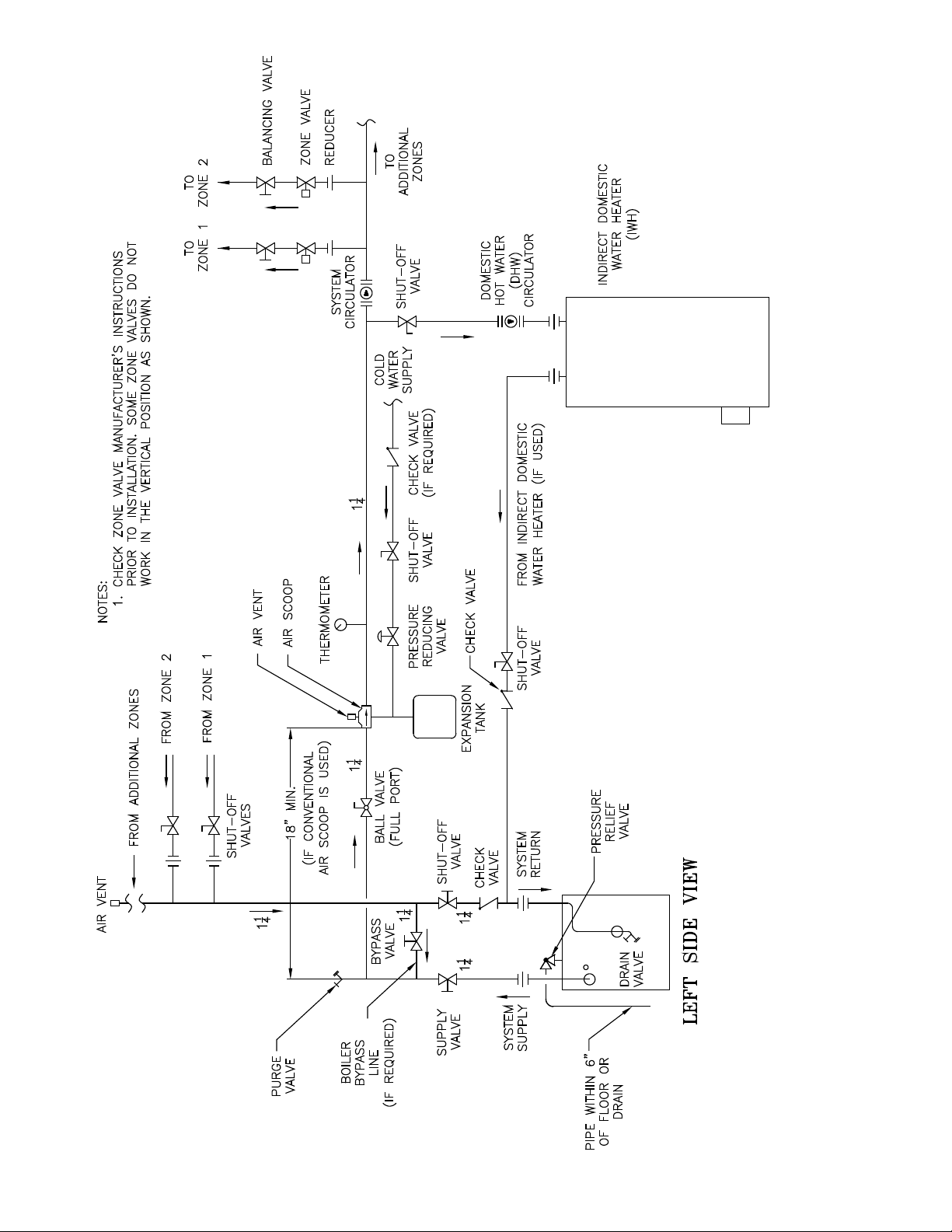
Figure 5: Recommended Water Piping for Zone Valve Zoned Heating Systems
8
Page 9
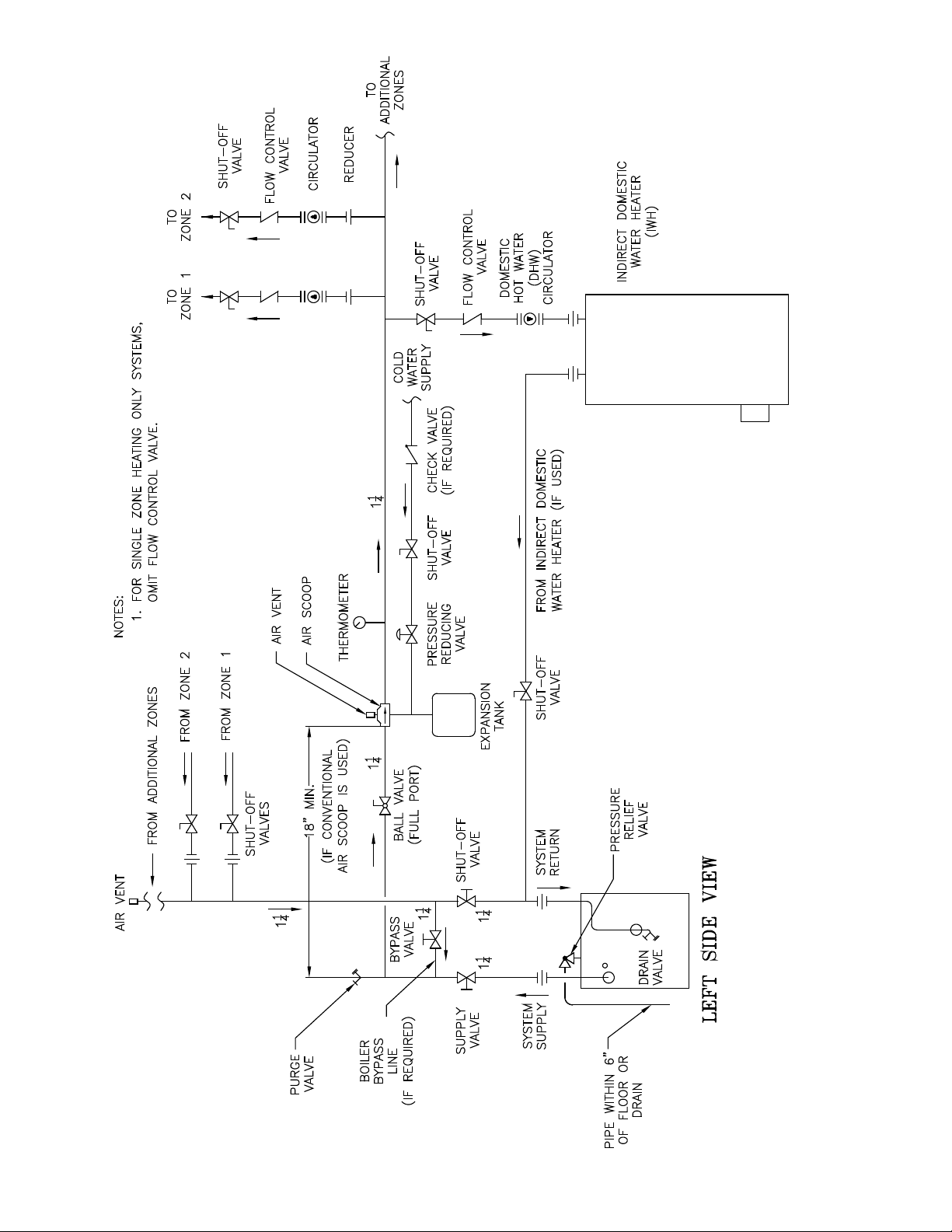
Figure 6: Recommended Water Piping for Circulator Zoned Heating Systems
9
Page 10
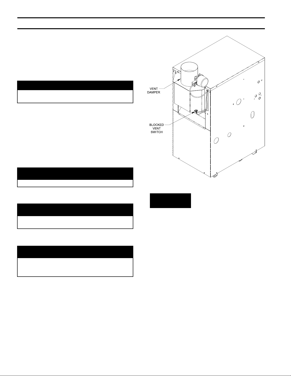
IV. Venting
A. Install Vent Damper
OPEN THE VENT DAMPER CARTON and remove the
Installation Instructions. READ THE INSTALLATION
INSTRUCTIONS THOROUGHLY before proceeding.
The automatic gas control valve supplied on each
CG-E Series boiler provides the redundancy referenced
in the vent damper Installation Instructions.
CAUTION
Do not use one vent damper to control two heating
appliances.
1. The vent damper must be the same size as the outlet
of the Draft Hood supplied with the boiler (see
Table 1A). Unpack the damper carefully - DO NOT
FORCE IT CLOSED! Forcing the damper may
damage the gear train and void the warranty.
2. Mount the vent damper assembly onto the canopy/
diverter. (Refer to Figure 7 and to instructions
packed with the vent damper for specic
instructions). Do not modify either the draft hood or
vent damper.
NOTICE
Provide adequate clearance for servicing.
3. Locate vent damper position indicating means to be
visible following installation.
WARNING
Provide 6" minimum clearance between damper
and combustible construction.
4. Plug the factory harness vent damper connector into
damper motor polarized receptacle.
DANGER
Inspect existing chimney before installing boiler.
Failure to clean or replace perforated pipe or tile
lining will cause severe injury or death.
B. Inspect chimney and remove any obstructions or
restric tions. Clean chimney if previously used for solid
or liquid fuel-burning appliances or replaces.
C. Install vent system in accordance with "Venting of
Equipment" of the National Fuel Gas Code, ANSI
Z223.1/NFPA 54, or applicable provisions of local
building codes. The CG-E Series boiler is a Category I,
draft hood equipped appliance.
Figure 7: Vent Damper Installation
WARNING
D. If an Existing Boiler is Removed:
When an existing boiler is removed from a common
venting system, the common venting system is likely
to be too large for proper venting of the appliances
remaining connected to it.
At the time of removal of an existing boiler, the
following steps shall be followed with each appliance
remaining connected to the common venting system
placed in operation, while the other appliances
remaining connected to the common venting system are
not in operation:
a. Seal any unused openings in the common venting
system.
b. Visually inspect the venting system for proper
size and horizontal pitch and determine there is no
blockage or restriction, leakage, corrosion, and other
deciencies which could cause an unsafe condition.
c. Insofar as is practical, close all building doors and
windows and all doors between the space in which
the appliances remaining connected to the common
venting system are located and other spaces of the
10
Page 11

building. Turn on clothes dryers and any appliance
not connected to the common venting system.
Turn on any exhaust fans, such as range hoods and
bathroom exhausts, so they will operate at maxi mum
speed. Do not operate a summer exhaust fan. Close
replace dampers.
d. Place in operation the appliance being inspected.
Follow the Lighting (or Operating) Instructions.
Adjust thermo stat so appliance will operate
continuously.
e. Test for spillage at the draft hood relief opening after
5 minutes of main burner operation. Use the ame
of a match or candle, or smoke from a cigarette,
cigar or pipe.
f. After it has been determined that each appliance
remain ing connected to the common venting system
properly vents when tested as outlined above, return
doors, win dows, exhaust fans, replace dampers and
any other gas-burning appliance to their previous
condition of use.
g. Any improper operation of the common venting
system should be corrected so the installation
conforms with the National Fuel Gas Code, ANSI
Z223.1/NFPA 54. When resizing any portion of
the common venting system, the common venting
system should be resized to approach the minimum
size as determined using the appropriate tables in
Chapter 13 of the National Fuel Gas Code, ANSI
Z223.1/NFPA 54.
11
Page 12
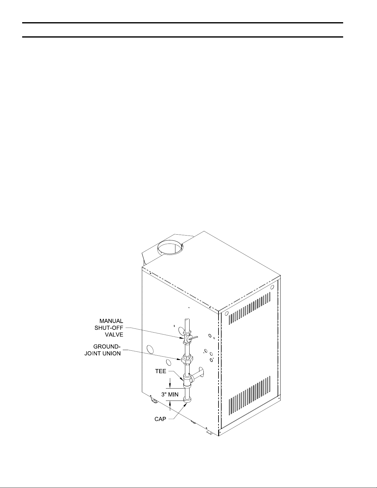
V. Gas Piping
A. Size gas piping. Design system to provide adequate gas
supply to boiler. Consider these factors:
1. Allowable pressure drop from point of delivery to
boiler. Maximum allowable system pressure is ½
psig. Actual point of delivery pressure may be less;
contact gas supplier for additional information.
Minimum gas valve inlet pressure is listed on rating
label.
2. Maximum gas demand. Consider existing and
expected future gas utilization equipment (i.e. water
heater, cooking equipment).
3. See Table 1B for boiler inputs.
B. Connect boiler gas valve to gas supply system.
1. Use methods and materials in accordance with local
plumbing codes and requirements of gas supplier. In
absence of such requirements, follow National Fuel
Gas Code, ANSI Z223.1/NFPA 54.
2. Use thread (joint) compounds (pipe dope) resistant
to action of liqueed petroleum gas.
3. Install sediment trap, ground-joint union and manual
shut-off valve upstream of boiler gas control valve.
See Figure 8.
4. All above ground gas piping upstream from manual
shut-off valve must be electrically continuous and
bonded to a grounding electrode. Do not use gas
piping as grounding electrode. Refer to National
Electrical Code, ANSI/NFPA 70.
C. Pressure test. The boiler and its gas connection must
be leak tested before placing boiler in operation.
1. Protect boiler gas control valve. For all testing over
½ psig, boiler and its individual shutoff valve must
be disconnected from gas supply piping. For testing
at ½ psig or less, isolate boiler from gas supply
piping by closing boiler's individual manual shutoff
valve.
2. Locate leaks using approved combustible gas
detector, soap and water, or similar nonammable
solution. Do not use matches, candles, open ames,
or other ignition source.
12
Figure 8: Pilot and Gas Piping
Page 13

VI. Electrical
A. General. Install wiring and electrically bond boiler to
ground in accordance with requirements of authority
having jurisdiction, or in absence of such requirements,
with the National Electrical Code, ANSI/NFPA 70.
B. Install thermostat. Locate on inside wall
approximately 4 feet above oor. Do not install on
outside wall, near replace, or where inuenced by
drafts or restricted air ow, hot or cold water pipes,
lighting xtures, television, or sunlight. Allow free air
movement by avoiding placement of furniture near
thermostat.
C. Wire boiler. Boiler is rated for 120 VAC, 60 hertz,
less than 12 amperes. A separate electrical circuit
must be run from the main electrical service with an
over-current device/disconnect in the circuit. A service
switch is recommended and may be required by some
local jurisdictions. Connect to black and white wires
and green ground screw. See Figures 9 and 10.
D. For installations using zone valves provide separate
transformer for zone valve wiring. Consult zone valve
manufacturer for assistance. See Figure 11.
CAUTION
This boiler contains controls which may cause
the boiler to shut down and not restart without
service. If damage due to frozen pipes is a
possibility, the heating system should not be
left unattended in cold weather; or appropriate
safeguards and alarms should be installed on the
heating system to prevent damage if the boiler is
inoperative.
13
Page 14
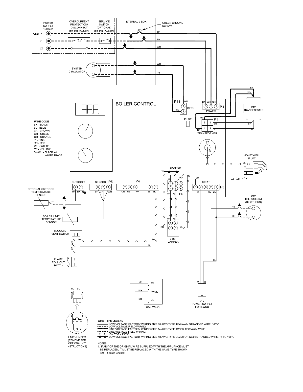
14
Figure 9: Wiring Connection Diagram
Page 15
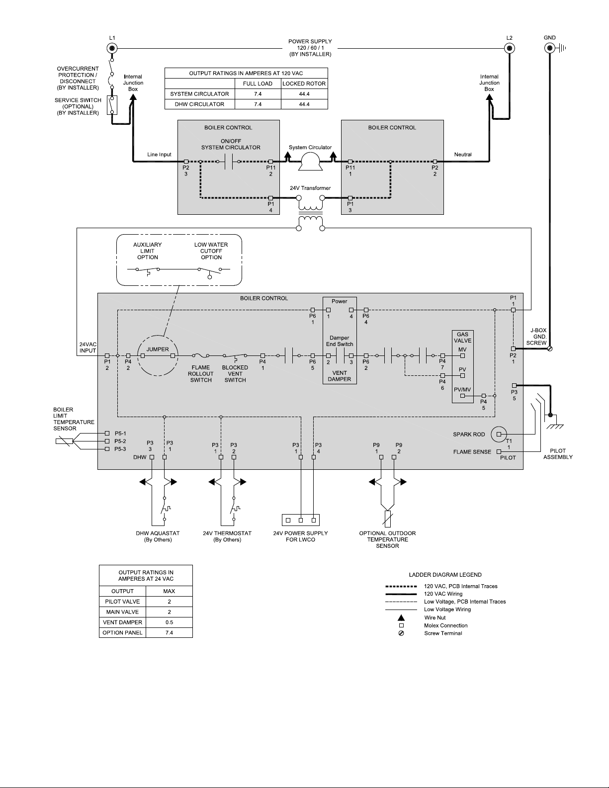
Figure 10: Schematic Ladder Diagram
15
Page 16
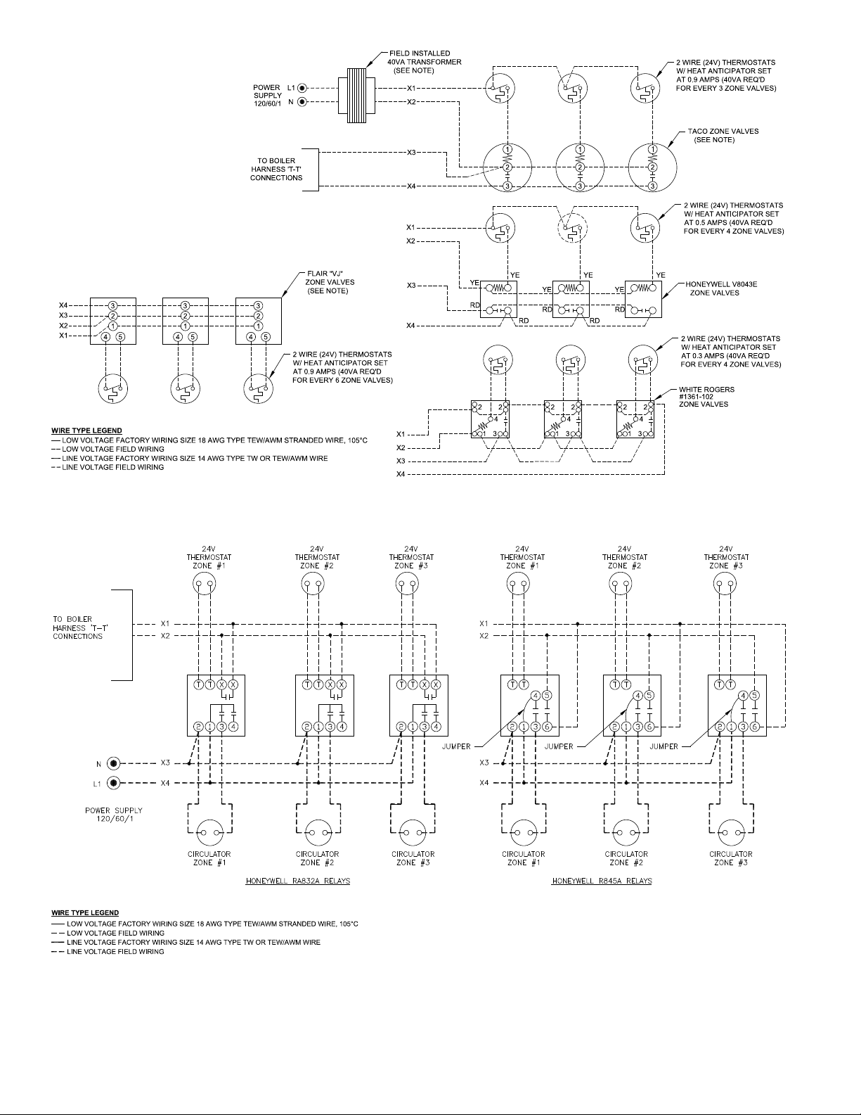
Figure 11: Wiring Schematic, Zone Valves
16
Figure 12: Wiring Schematic, Zone Circulators
Page 17

VII. System Start-up and Checkout
A. Main Burner Check - Check main burners to see
that they were not dislodged during shipment. Rear
of burners should be in the vertical slots in the rear of
burner tray and the front of the burners should be seated
completely on the orices.
B. Initial start -
1. Fill entire heating system with water and vent
air from system. Use the following procedure on a
System equipped with zone valves.
a. Close isolation valve in boiler supply piping.
b. Isolate all circuits by closing zone valves or
balancing valves.
c. Attach a hose to hose bib located just below
isolation valve in boiler supply piping. (Note
- Terminate hose in ve gallon bucket, at a
suitable oor drain, or outdoor area).
d. Starting with one circuit, open zone valve.
e. Open hose bib.
f. Open ll valve (Make-up water line should be
located directly above isolation valve in boiler
supply piping).
g. Allow water to overow from bucket until
discharge from hose is bubble free for 30
seconds.
h. Open zone valve to the second zone to be
purged, then close the rst. Repeat this step until
all zones have been purged, but always have one
zone open. At completion, open all zone valves.
i. Close hose bib, continue lling the system
until the pressure gauge reads 12 psi. Close ll
valve. (Note - If make-up water line is equipped
with pressure reducing valve, system will
automatically ll to 12 psi. Leave globe valve
open).
j. Open isolation valve in boiler supply piping.
k. Remove hose from hose bib.
2. Turn ROOM THERMOSTAT to lowest setting.
3. Be sure that gas to pilot and main burners has been
off for at least ve minutes and vent damper has
been in the open position.
4. Turn "OFF" the electric switch serving boiler.
5. Open valve on main gas line at meter.
6. PURGE AIR FROM GAS PIPING. Adequate
ventilation must be provided and no smoking or
open ame permitted.
7. Turn "ON" electric switch serving boiler.
8. Open Manual Shut-off Valve upstream of
Combination Gas Valve.
Figure 13: Top View of Honeywell Gas Valves
9. Loosen or remove Inlet Pressure Tap Plug in
Combination Gas Valve and when purging is
complete, tighten or replace plug. (See Figure 13).
10. Check pipe and ttings from meter to Combination
Gas Valve using soap solution or other approved
methods.
CAUTION
11. Test gas piping and connections between
Combination Gas Valve and manifold, orices, and
pilot piping for leaks after boiler is operating. Use
soap solution or other approved method.
C. Check Gas Input to Boiler
1. Input Rate and Maximum Inlet Pressure shown on
Rating Label must not be exceeded. Inlet pressure
must not be lower than minimum inlet pressure
shown on Rating Label.
2. Input ratings shown on boiler rating label can be
used for elevations up to 2000 ft. For elevations
2000 ft or higher, reduce input rate 4 percent per
1000 ft above sea level. Do not install at elevations
above 12,000 ft. See Table below.
Boiler
Model
CG30E 70.0 56.0 49.0 42.0
CG40E 105.0 84.0 73.5 63.0
CG50E 140.0 112.0 98.0 84.0
CG60E 175.0 140.0 122.5 105.0
CG70E 210.0 168.0 147.0 126.0
CG80E 245.0 196.0 171.5 147.0
CG90E 280.0 224.0 196.0 168.0
Rating
Label
3. All Rate checks and all adjustments are to be made
while boiler is ring - all other appliances connected
to the same meter as the boiler must be off.
(1525 m)
Input [Mbh]
5000 ft.
7,000 ft.
(2130 m)
10,000 ft.
(3050 m)
17
Page 18
18
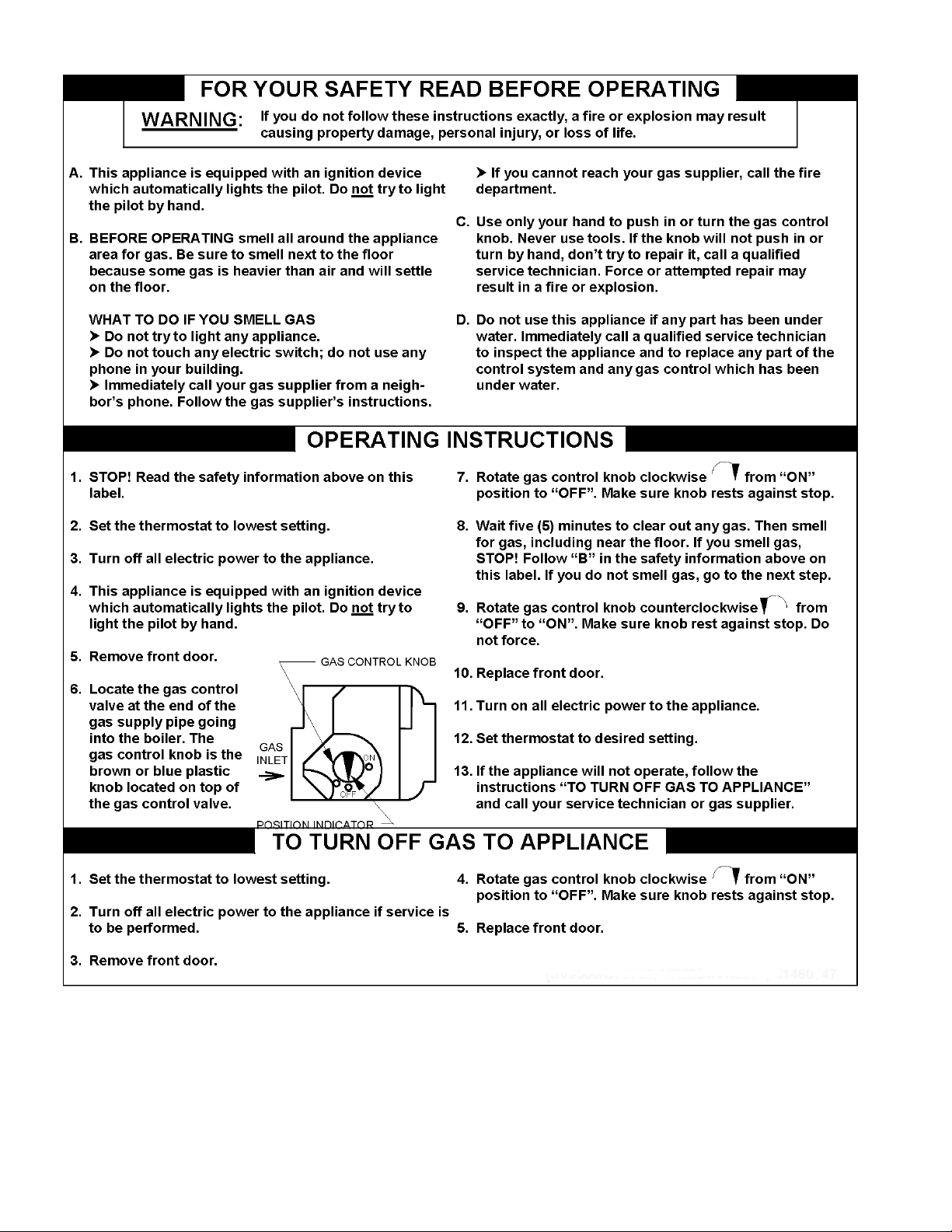
Figure 14: Operating Instructions
Page 19
4. With boiler off, water Manometer or water column
gauge should be connected to a shut-off valve
installed in the 1/8" outlet pressure tap in the gas
valve (see Figure 13). By installing gas valve
upstream of manometer, gas pressure can be
introduced gradually - without shut-off valve; surge
of pressure when boiler is turned on, could blow
liquid out of manometer. Replace plug in gas valve
when rate check is nished.
5. Lp Gas Input:
Adjust Regulator on Gas Valve so that manifold
pressure is 10 inches water column. Turning
Regulator Adjusting Screw Clockwise increases
pressure. Counterclockwise rotation decreases
pressure.
6. Natural Gas Input:
Adjust Regulator on Gas Valve so that manifold
pressure is 3½ inches water column. Turning
Regulator Adjusting Screw Clockwise increases
pressure. Counter-clockwise rotation decreases
pressure.
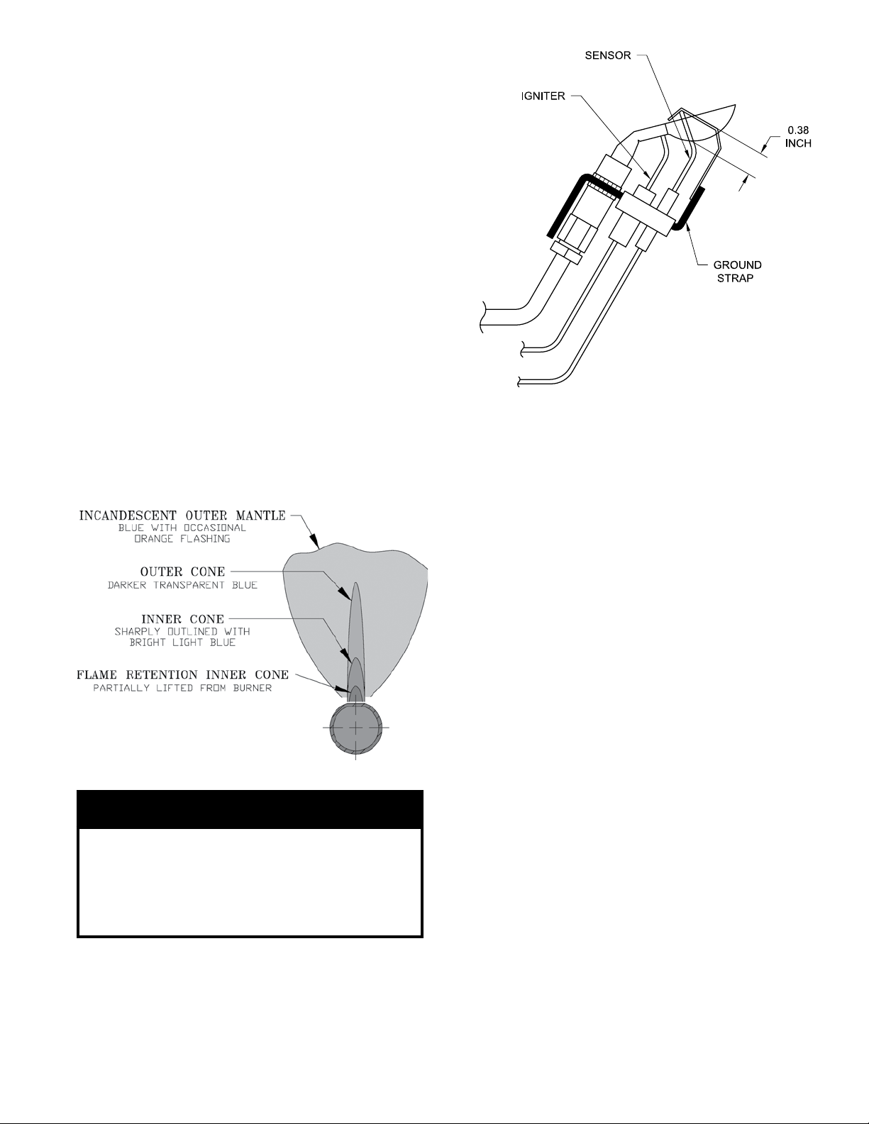
Figure 16: Pilot Burner Flame
D. Check Main Burner Flame. See Figure 15. Flame
should have a clearly dened inner cone with no yellow
tipping. Orange-yellow streaks caused by dust should
not be confused with true yellow tipping.
Figure 15: Main Burner Flame
CAUTION
Avoid operating this boiler in an environment
where saw dust, loose insulation bers, dry wall
dust, etc. are present. If boiler is operated under
these conditions, the burner interior and ports
must be cleaned and inspected daily to insure
proper operation.
E. Check Pilot Burner Flame.
1. See Figure 16. The pilot burner should be lit only
if thermostat is calling for heat. The pilot burner
produces three (3) ames. The center ame should
be steady, medium hard blue enveloping 3/8 to 1/2
inch of sensing probe.
F. Check Ignition System Safety Shut-off Device.
Remove 3-wire plug from gas valve.
If burners do not shut down determine cause of
malfunction. Replace necessary items and check
operation.
G. Check Vent Damper Operation. Vent Damper must
be in open position when main burners are operating.
H. Check High Limit Control.
Jumper Thermostat connections in boiler wiring
harness. Allow burners to operate until shutdown by
limit. REMOVE JUMPER.
I. Check Thermostat Operation. Raise and lower
temperature setting to start and stop boiler operation.
Adjust thermostat to normal setting.
J. Combustion Chamber Burn-off
1. The mineral wool combustion chamber panels
may contain a cornstarch based binder that must be
burned out at installation to prevent odors during
subsequent boiler operation.
2. Ventilate the boiler room, set the high limit to its
maximum setting, set the thermostat to call for heat.
Allow the boiler to re for at least an hour or until
the odor from the cornstarch has dissipated.
3. Return the high limit and thermostat to their desired
settings.
K. Review User's Information Manual and system
operation with owner or operator.
L. Post instructions near boiler for reference by owner
and service personnel.
19
Page 20
VIII. Operation
A. BOILER SEQUENCE OF OPERATION
NORMAL OPERATION
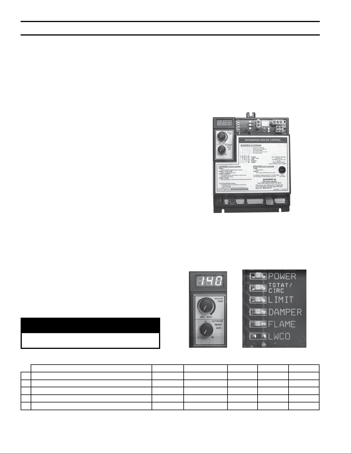
1. The CG-E Series Boilers are equipped with an
Integrated Boiler Control (IBC). This IBC replaces
the traditional separate ignition control, high limit
switch and circulator relay and adds energy saving
thermal purge features. Energy is saved by starting
the circulator and delaying the burner start when
there is residual heat available in the boiler.
2. The boiler’s sequence of operation is shown in
Table 2.
3. When the thermostat calls for central heat (CH) the
IBC starts the system circulator and the thermal
purge begins. If the boiler temperature is less than
140°F, the start sequence continues by energizing
the vent damper. Once the vent damper is fully
open the ignition sequence is started allowing gas
in open position when appliance main burners are
operating.
setpoint is reached the system circulator will
continue to operate and the burners will stop.
When the boiler water temperature drops below the
setpoint less the differential setting the burners will
restart.
circulator are stopped and vent damper is closed.
6. When an indirect water heater aquastat call for
the circulator and, if the boiler temperature is less
than the operating setpoint less differential, the vent
damper is energized without delay. Once the vent
damper is fully open, the ignition sequence is started
high limit will match CH set point if CH set point is
below 200°F.
B. BOILER FAULT
In the event the boiler fails to start, the control provides
status information to help determine the cause of the
problem. Table 3 from Section X: Troubleshooting
the source of the lockout. Refer to the Troubleshooting
Section for more information.
C.
The control is located inside the boiler. (Figure 17).
Figure 17: Integrated Boiler Control
The IBC display, along with two adjustment knobs may
located to the right of the display. When powered the
light up red depending on the state of the control (see
Figure 18).
NOTICE
DHW Thermostat should only be used for systems
with zone valves, see Figure 5.
Table 2: Sequence of Operation Using the Controls LEDs
Status POWER TSTAT/CIRC LIMIT DAMPER FLAME
1 Standby
2 Call for heat - Circulator on
3 Limit circuit closed
4 Vent Damper - Proven open
5 Pilot ame proven
- LED illuminated
- LED off
20
Figure 18: Boiler Display
Page 21
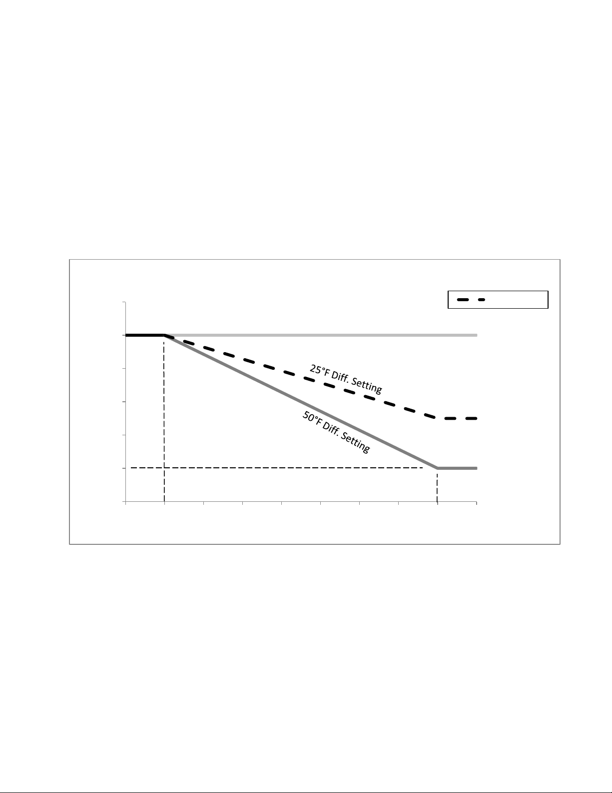
1. High limit setpoint
0°F Diff. Setting
The High Limit Setpoint is user adjustable by
turning the top knob labeled “BOILER TEMP”.
Adjustment range is 140°F to 220°F. During
normal operation the LED display will show boiler
temperature. When a change is made to the setpoint
knob the display will brighten and show the setpoint.
Factory programmed with High Limit Setpoint of
140°F.
Outdoor Reset
2. Outdoor Reset Differential Setpoint (when outdoor
sensor installed)
The Outdoor Reset Differential Setpoint is user
adjustable by turning the bottom knob labeled
“OUTDOOR RESET DIFF”. Adjustment range is
0°F to 50°F. When no outdoor sensor is present, the
IBC uses the user setpoint as the operating setpoint.
When an outdoor temperature sensor is attached,
the IBC adjusts the Conditioned space demand
operating setpoint based on outdoor temperature.
See graph below.
190
180
170
160
150
Boiler Operating Setpoint (°F)
140
130
-10 0 10 20 30 40 50 60 70 80
Outdoor Temperature (°F)
25°F (default)
21
Page 22
IX. Service and Maintenance
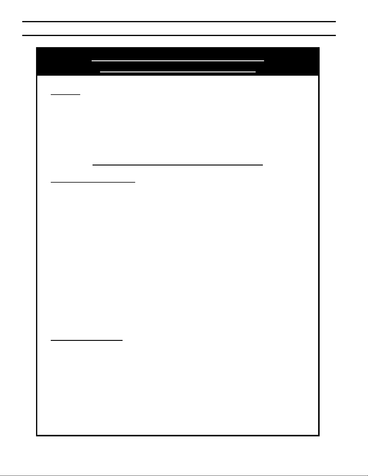
Refractory Ceramic Fiber Product
Important Product Safety Information
Warning:
The Repair Parts list designates parts that contain refractory ceramic fibers
(RCF). RCF has been classified as a possible human carcinogen. When
exposed to temperatures above 1805°F, such as during direct flame contact,
RCF changes into crystalline silica, a known carcinogen. When disturbed as a
result of servicing or repair, these substances become airborne and, if inhaled,
may be hazardous to your health.
AVOID Breathing Fiber Particulates and Dust
Precautionary Measures:
Do not remove or replace RCF parts or attempt any service or repair work
involving RCF without wearing the following protective gear:
1. A National Institute for Occupational Safety and Health (NIOSH)
approved respirator
2. Long sleeved, loose fitting clothing
3. Gloves
4. Eye Protection
• Take steps to assure adequate ventilation.
• Wash all exposed body areas gently with soap and water after contact.
• Wash work clothes separately from other laundry and rinse washing
machine after use to avoid contaminating other clothes.
• Discard used RCF components by sealing in an airtight plastic bag. RCF
and crystalline silica are not classified as hazardous wastes in the United
States and Canada.
First Aid Procedures:
• If contact with eyes: Flush with water for at least 15 minutes. Seek
immediate medical attention if irritation persists.
• If contact with skin: Wash affected area gently with soap and water.
Seek immediate medical attention if irritation persists.
22
• If breathing difficulty develops: Leave the area and move to a location
with clean fresh air. Seek immediate medical attention if breathing
difficulties persist.
• Ingestion: Do not induce vomiting. Drink plenty of water. Seek
immediate medical attention.
Page 23
WARNING
Service on this boiler should be undertaken only by trained and skilled personnel from a qualied
service agency. Inspections should be performed at intervals specied in this manual. Maintain
manual in a legible condition.
Keep boiler area clear and free of combustible materials, gasoline and other ammable vapors and
liquids.
Do not place any obstructions in boiler room that will hinder ow of combustion and ventilation air.
A. General. Inspection and service should be conducted
annually. Turn off electrical power and gas supply
while conducting service or maintenance. Follow
instructions TO TURN OFF GAS TO APPLIANCE.
See Figure 14.
CAUTION
Label all wires prior to disconnection when
servicing controls. Wiring errors can cause
improper and dangerous operation. Verify proper
operation after servicing.
B. Inspect Vent System.
1. Remove obstructions in vent pipe and chimney.
2. Remove soot accumulations with wire brush and
vacuum.
3. Repair or replace deteriorated vent pipe and vent
accessories.
4. Provide proper support. Repair sags, particularly in
horizontal sections.
5. Repair leaking joints.
C. Inspect Boiler Flue Passages for blockage or soot
accumulation.
1. Remove vent pipe, vent damper and blocked vent
switch.
2. Remove sheet metal screws securing Jacket Top
Panel. Remove Top Panel.
3. Remove screws securing Canopy to Section
Assembly. Remove Canopy.
4. Using ashlight, examine all ue passageways.
a. If passageways are free of soot and obstruction,
replace canopy, secure and seal.
b. If passageways need cleaning, remove burners
as described in Paragraph D. Using long handle
wire or bristle ue brush and vacuum, brush
ueways thoroughly from top of boiler.
5. Install new gasket material (See Section XI: Repair
Parts). Install canopy.
6. Install Jacket Top Panel, Blocked Vent Switch, Vent
Damper, and vent pipe.
D. Clean Main Burners and Firebox.
1. To remove burners for cleaning, changing orices,
or repairs:
a. Remove Jacket Front Panel.
b. Disconnect pilot tubing at gas valve.
c. Disconnect 3-wire plug at the gas valve.
d. Remove wires to ame roll-out switch.
e. Remove the burner access panel.
f. Mark the location of the pilot main burner on the
manifold if the marking on manifold is missing
or obliterated.
g. Hold burner at throat. Lift front of burner to
clear orice. Burner which holds pilot can only
be removed by lifting the burner adjacent to its
right rst.
2. Brush top of burners with a soft bristle brush.
Vacuum burners.
3. Check orices. Drilled passageways must be free of
lint or dirt.
4. Vacuum tip of Pilot Burner.
5. Clean rebox by vacuuming. Exercise care not to
damage base insulation.
6. Install burners by reversing procedure used to
remove burners. Make sure burner with pilot
assembly is in same location as original installation.
Check burners to see that they are located properly
in slot at rear of burner tray. Reinstall burner access
panel. Reconnect ame roll-out switch wires, pilot
gas supply, thermocouple lead or pilot lead.
7. Connect pilot gas supply, igniter/sensor wire, and
ground wire at Boiler Control.
8. Install Burner Access Panel. Connect Flame Rollout
Switch wires.
E. Check Operation. Follow steps C through J from
Section VII: System Start-up and Checkout.
F. Lubrication. There are no parts requiring lubrication
by service technician or owner. Circulator bearings are
water lubricated.
23
Page 24
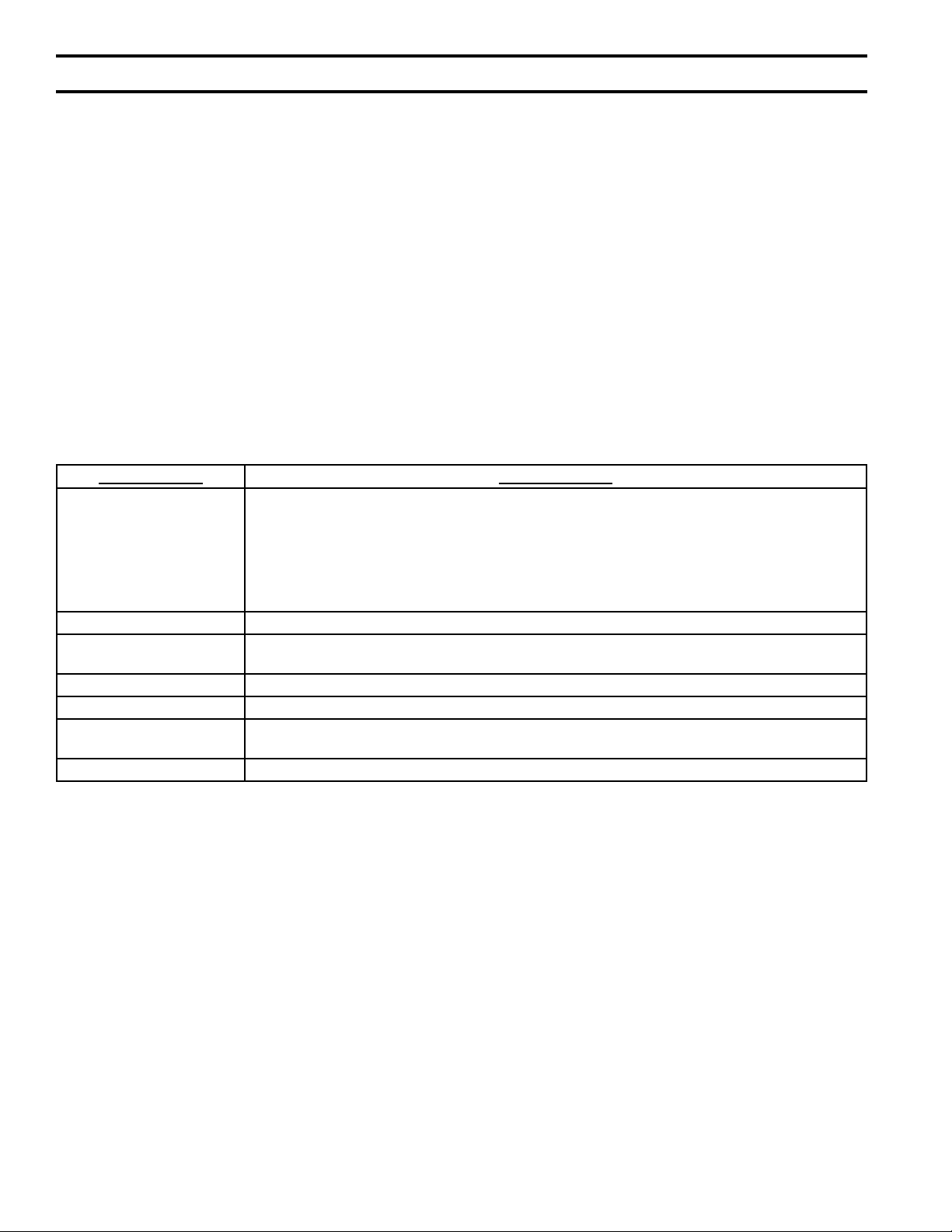
X. Troubleshooting
A. BEFORE TROUBLESHOOTING
The following pages contain troubleshooting tables for
use in diagnosing control problems. When using these
tables the following should be kept in mind:
1. This information is only meant to be used by
a professional heating technician as an aid in
diagnosing boiler problems.
2. In general, these tables assume that there are no
loose or miswired electrical connections. Before
using these tables inspect all electrical connections
on the boiler to make sure that they are tight. Also,
check the wiring on the boiler against the wiring
diagram in Figures 9 and 10. Ensure that incoming
120 Vac power polarity is correct and that the boiler
is properly grounded. Further, ensure that the control
power supply is 24 VAC (minimum 18 VAC to
maximum 30 VAC) and polarity is correct.
4. All controls on the CG-E Series are tested at least
once in the manufacturing process and a defective
control or component is generally the least likely
cause. Before replacing a component, try to rule out
all other possible causes.
5. When checking voltage across wiring harness pins
be careful not to insert the meter probes into the
loose connection when the harness is reconnected.
Table 3: Troubleshooting Using the Control's LED
Flashing LED Fault Condition
POWER
Steady 1 Hz ash
Flash code 2
Flash code 3
Flash code 4
Flash code 5
Flash code 6
POWER + TSTAT/CIRC 48 volts on Thermostat circuit
DAMPER Damper switch opened after it had been proved closed. Continues ashing until demand for heat
POWER + DAMPER Damper switch stuck open or closed (control in damper switch lockout)
LIMIT Fault detected in temperature sensing hardware
FLAME Flame loss, or ame not sensed during trial for ignition. Continues ashing until either ame is
POWER + FLAME Flame sensed without call for heat or out of sequence during ignition trial.
Reverse polarity of 115 VAC supply voltage
Faults internal to microprocessor (RAM, ROM, etc.)
Unused
Unused
Water thermistors disagree
Gas valve outputs in improper state
removed or Damper switch proven closed in ignition sequence.
established or demand for heat is removed.
Lockouts
1. Lockout from internal hardware faults (listed above under POWER) automatically resets after the hardware fault has
not been present for 60 minutes. Lockouts from internal hardware faults may not be manually reset except by removing
power from the control.
2. Lockout from damper switch failing to close within 45 seconds automatically resets after 60 minutes. Lockout may be
manually reset by opening the thermostat for more than 2 but less then 20 seconds.
24
Page 25
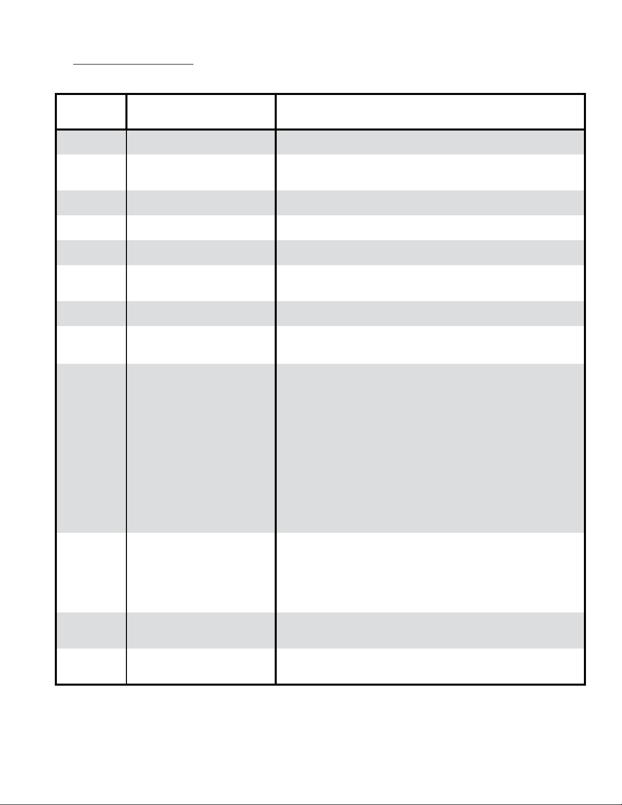
B. S
If the control detects an error,
:
Flashing
LEDs
Blank Boiler or Control is not powered
POWER
Steady 1 Hz
ash
POWER
Flash Code 2
POWER
Flash Code 5
POWER
Flash Code 6
POWER
+
TSTAT/CIRC
DAMPER
POWER
+
DAMPER
POWER
+
DAMPER
LIMIT Temperature Sensor Failure
FLAME
POWER
+
FLAME
Line Voltage Reversed Reverse polarity of 115 VAC supply voltage.
Microprocessor Failure Cycle power to control. Replace control if problem persists.
Water thermistors disagree
Gas Valve Outputs in improper
state
Thermostat Input Higher than
Threshold
Damper Switch opened after
proven closed
Damper Failed to Open
Damper Failed to Close
Flame Current Lower than
Threshold
Flame Sensed Out of Normal
Sequence
Status Recommended Corrective Action
No 120 Vac Power at boiler, check breaker and wiring between breaker
panel and boiler
Conrm sensor is fully in well. If secure and good condition, replace
sensor.
Flame sensed during pre-purge (before gas valve signaled open). Check
the gas valve for proper operation. Replace gas valve if problem persists.
Check thermostat wiring.
LEDs continue ashing until demand for heat is removed or damper switch
proven closed in ignition sequence.
Atmospheric Damper End Switch failed to close (end switch contacts stuck
open). Refer to Troubleshooting Section, C4.
Damper open. Voltage should not be present on P6-5. Control, vent
damper or wire harness is defective. While the POWER + DAMPER LEDs
ash on the control, perform the following tasks:
• Remove the call for heat (adjust thermostat or remove wire from TT
terminals.
• Check for 24Vac between P6-5 and ground.
• If voltage not present, attempt to start boiler again.
• If 24Vac is present, unplug the vent damper harness from control.
• With wire harness unplugged, check for 24Vac between P6-5 (on
Control) and ground.
• If voltage present, replace the control.
• If voltage not present, failed vent damper or wiring harness.
• Check wiring harness for shorts or mis-wiring. Replace if defective.
• If harness not defective, replace vent damper.
Temperature sensor or interface failure (open or short connection,
increased connection resistance, dual sensor mismatch) or control
hardware failure.
- Check sensor is securely attached to control P7 connector.
- Check sensor wire is not damaged.
- If secure and in good condition, replace sensor.
- If problem persists, replace control.
Flame loss, or ame not sensed during trial for ignition. Continues ashing
until either ame is established or demand for heat is removed.
Check pilot assembly. Refer to Troubleshooting Section, C5.
Flame sensed out of normal sequence (before opening gas valve or after
closing gas valve). Check the gas valve for proper operation.
25
Page 26
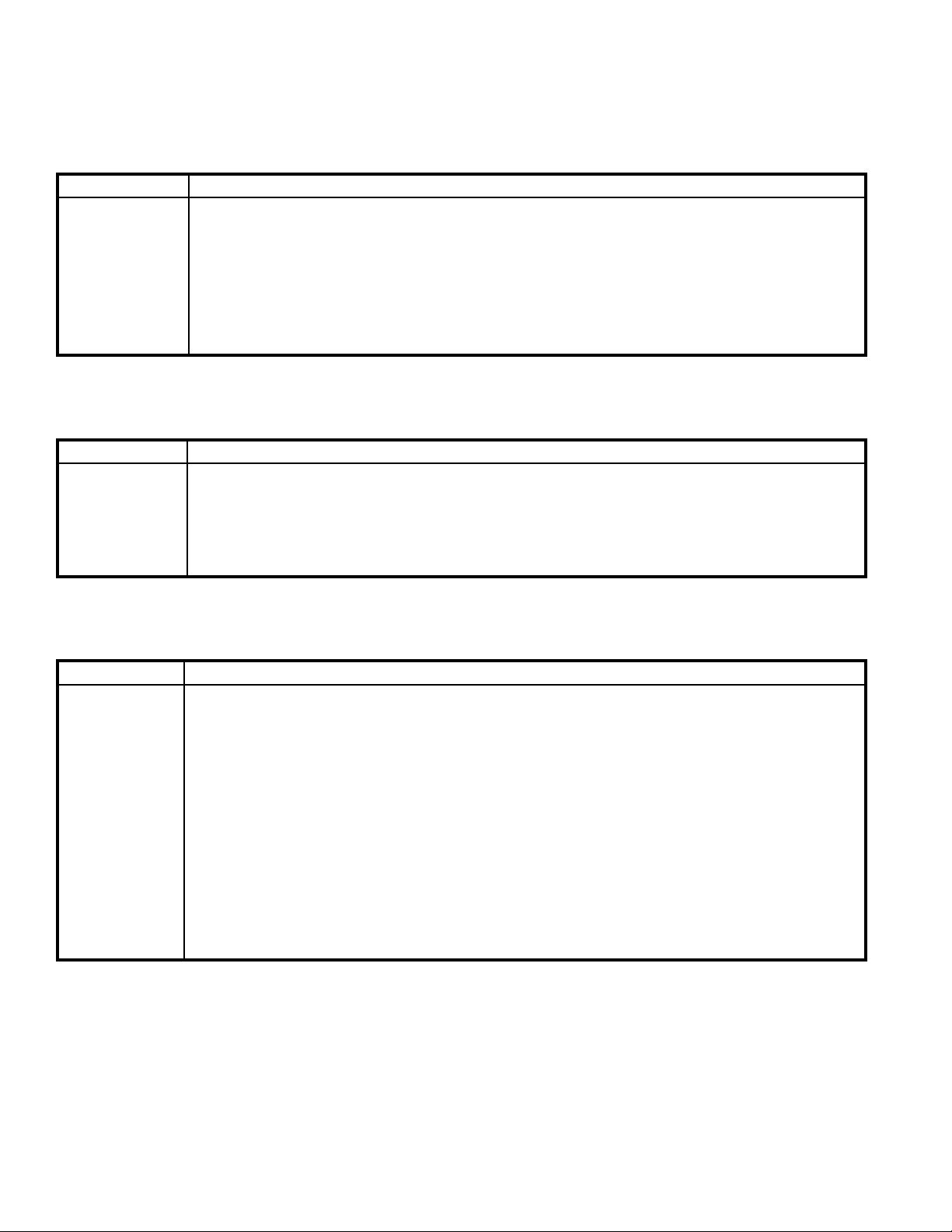
C. USE STATUS LEDS TO GUIDE TROUBLESHOOTING
The control LEDs will light to indicate status. Use these LEDs to identify the boiler problem in the table below:
1. Boiler and Circulator Off
LED / Status Recommended Corrective Action
The boiler has not detected a call for heat
- POWER
Standby
Burner off
Circulator off
Check that the thermostat:
- When a thermostat call for heat is detected control TSTAT/CIRC LED will be lit.
- Make sure thermostat is calling for heat and contacts (including appropriate zone controls) are closed.
Check for loose connection.
Check the DHW demand:
- When a domestic call for heat is detected control TSTAT/CIRC LED will be lit.
- Make sure the DHW aquastat contact is closed. Check for loose connection.
2. Circulator is On, But Boiler is Off
LED / Status Recommended Corrective Action
- POWER
- TSTAT/CIRC
Circulator
Pre-purge
Burner off
Circulator on
The boiler is warm and circulator is providing residual boiler heat to building:
Check boiler temperature
- The boiler will not start until boiler water temperature is 15°F less than the Setpoint
- If boiler water temperature is higher than 140° F, boiler start will be delayed until water temperature
drops below 140°F.
3. Circulator is On But Damper is Not Open
LED / Status Recommended Corrective Action
Waiting for Limit to Open.
- Check Blocked Vent Switch, in the event of a blocked vent or poor draft condition, the blocked vent switch
will open interrupting power to control P4-1. The main burners will be extinguished immediately and the
circulator will remain on until the thermostat is turned off. The source of blockage must be corrected by
trained and skilled personnel from a qualied service agency before resetting switch.
Blocked Vents are caused by a collapsed chimney resulting in full or partial blockage, chimney cross
- POWER
- TSTAT/CIRC
Limit Open
sectional area too small, height insufcient or cold chimney causing sustained poor draft. Always follow
the recommendations in Section I, Figure 1 and Section IV: Venting.
- Check Flame Rollout Switch, in the event of excessive blockage of the boiler section ue passageways
is developed the ame rollout switch will open interrupting power to control P4-1. The main burners will
be extinguished immediately and the circulator will remain on until the thermostat is turned off. If the
ame rollout switch is activated, do not attempt to place the boiler in operation. The source of the
blockage must be corrected and the identical ame rollout switch replaced by trained and skilled
personnel from a qualied service agency.
- Check External Limit.
26
Page 27
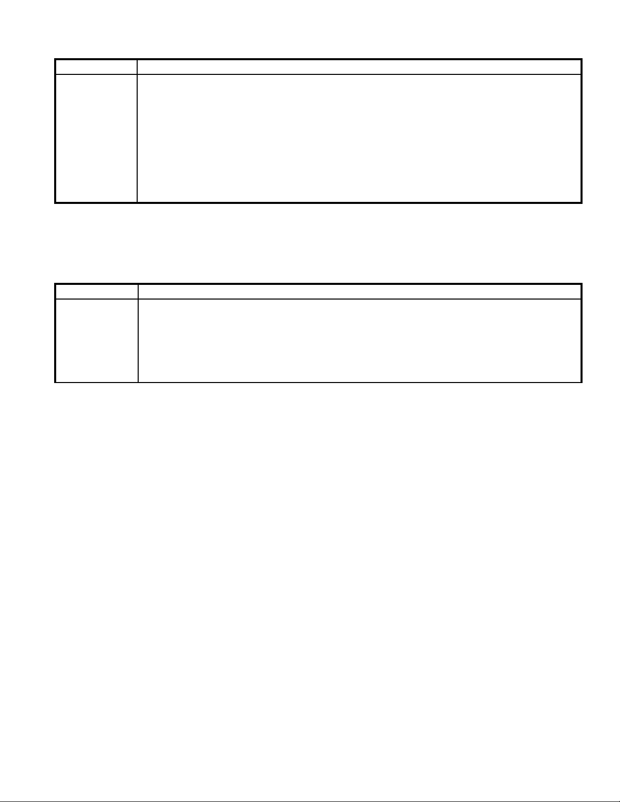
4. Circulator is On But Damper is Not Open
LED / Status Recommended Corrective Action
The control is waiting for the damper to open. Damper end switch has failed to close (end switch contact is
stuck open). Combustion can never take place unless the damper blade is in the fully open position. Check
the following:
- POWER
- TSTAT/CIRC
- LIMIT
Damper Failed
to Open
- Conrm if control terminal “P6 - 5” (yellow wire) is energized.
- Check for loose connection between control and vent damper, check damper harness.
- Check for obstruction in path of damper
- When damper is open (end switch closed) control terminal “P6 – 2” should receive power from the vent
damper.
- Place jumper between control terminal P6-5 and P6-2. If DAMPER LED does not light, replace control.
- Defective harness or vent damper.
5. Circulator is On, Damper is Open But Boiler Fails to Start
LED / Status Description
- POWER
- TSTAT/CIRC
- LIMIT
- DAMPER
Retry / Recycle
Delay
The Boiler is in “Retry Delay”:
- The burner failed to light (no ame signal). After a 5 minute delay, Control will attempt to light the burner
again. There is no limit to the number of retries.
Recycle Delay
- The burner loses ame during running mode. Immediately, Control will attempt to light the burner again.
If ame is lost 5 times within the same call for heat, the control locks out for one hour before retrying
ignition.
27
Page 28

5. Circulator is On, Damper is Open But Boiler Fails to Start (continued)
LED / Status Recommended Corrective Action
1. No Spark
a. Can you hear sparking?
- If there is no spark noise replace the control.
b. If you can hear spark noise check the following:
- Loose connection in ignition cable or ground wire
- Continuity of ignition cable
- Break in ignition cable insulation
- Loose ground connection
- Break in pilot ceramic insulator
- Incorrect pilot spark gap
2. No Pilot Flame
a. If pilot does not light check the following:
- All manual gas valves are open
- Supply tubing is not plugged, kinked or leaking
- Gas line pressures are good
- POWER
- TSTAT/CIRC
- LIMIT
- DAMPER
Retry / Recycle
Delay
- Gas line is purged of air
- Pilot orice is not plugged (pilot gas is owing)
- Condensate quenching pilot
Note: It may be necessary to recycle the “call for heat” more than once to clear the pilot supply tubes
of air.
b. If no gas ow check the following:
- 24 volts across PV and MV/PV at gas valve, if voltage ok replace defective gas valve
- Check for break in wiring harness to gas valve
- 24 volts across control connector P4-6 and P4-7, if no voltage at control replace defective control
3. Spark does Not Stop When Pilot Lights
If the spark does not stop when the pilot lights check the following:
- Loose connection in ignition cable or ground wire
- Continuity of ignition cable
- Clean ame rod
- Pilot electrode porcelain cracked
- Pilot ame covers ame rod and is steady and blue, if not adjust pilot ame
- Low gas pressure at gas valve inlet
- Defective control
4. Main Flame Does Not Light
If the main burners do not light check the following:
- Check orice size and/or blockage
- 24 volts across control terminals P4-5 and P4-7? If no voltage while in defective control.
- 24 volts across MV and MV/PV at gas valve? Check for break in wiring harness to gas valve
- Defective gas valve
28
Page 29

XI. Repair Parts
All CG-E™ Series repair parts may be ordered through New Yorker Boiler Company, Inc. or its authorized
distributors.
Should you require assistance in locating a New Yorker Distributor in your area, or have questions regarding the
availability of New Yorker products or repair parts, please contact:
New Yorker Boiler Company, Inc.
P.O. Box 10
Hateld, Pennsylvania 19440-0010
Attn: Customer Service Department
www.newyorkerboiler.com
Section Assembly and Canopy Assembly ............................................... 30
Base Assembly ....................................................................................... 32
Burners, Manifold and Gas Valve (Natural and LP Gas) ........................ 34
Controls................................................................. ............................... 35
Jacket Assembly, Complete .................................................................... 36
Trim and Vent Damper ......................................................................... 37
29
Page 30
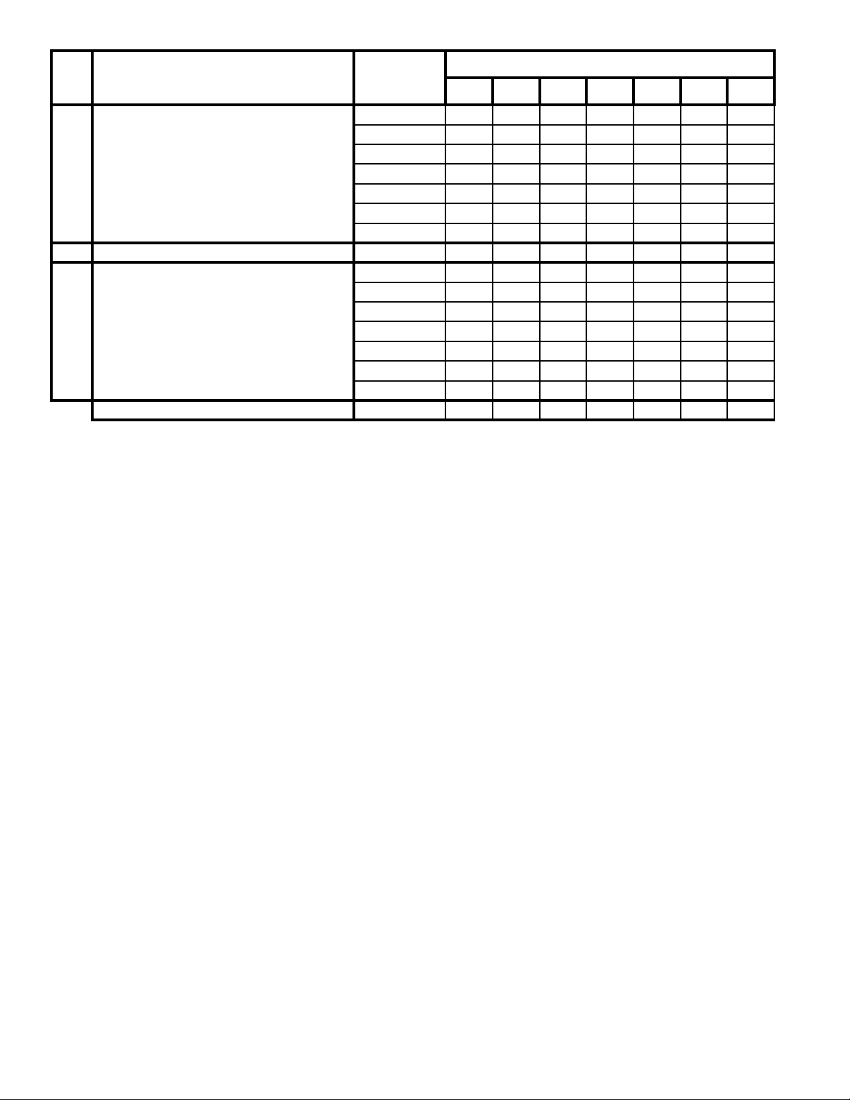
Key
No.
1A Cast Iron Section Assembly (Complete)
1B Canopy Gasket Kit 6201001 1 1 1 1 1 1 1
1C Canopy Assembly
Blocked Vent Switch (not shown) 80160157 1 1 1 1 1 1 1
Description Part Number
30 40 50 60 70 80 90
102287-03 1 --- --- --- --- --- ---
102287-04 --- 1 --- --- --- --- ---
102287-05 --- --- 1 --- --- --- ---
102287-06 --- --- --- 1 --- --- ---
102287-07 --- --- --- --- 1 --- ---
102287-08 --- --- --- --- --- 1 ---
102287-09 --- --- --- --- --- --- 1
102254-03 1 --- --- --- --- --- ---
102254-04 --- 1 --- --- --- --- ---
102254-05 --- --- 1 --- --- --- ---
102254-06 --- --- --- 1 --- --- ---
102254-07 --- --- --- --- 1 --- ---
102254-08 --- --- --- --- --- 1 ---
102254-09 --- --- --- --- --- --- 1
CG-E MODEL
30
Page 31
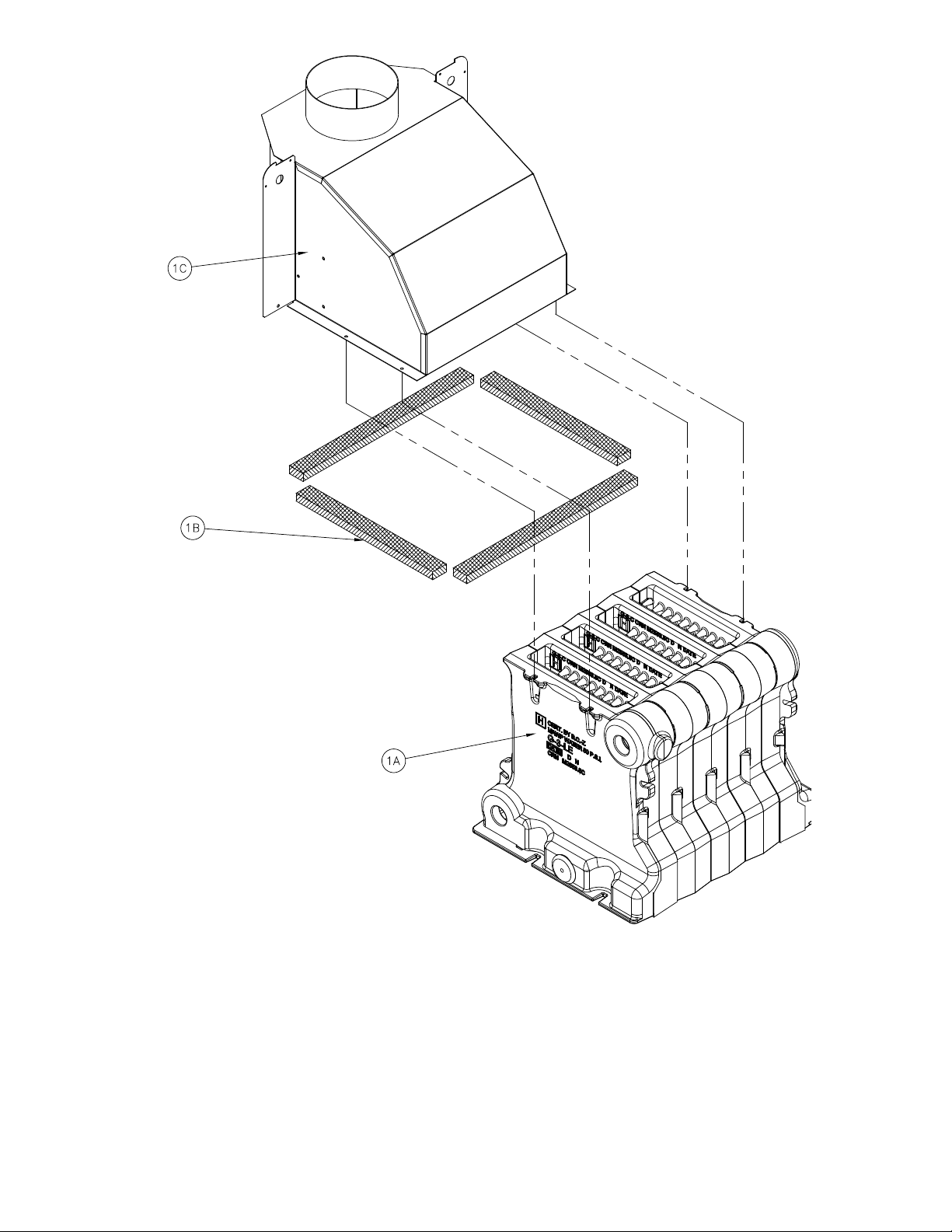
Section Assembly and Canopy Group
31
Page 32
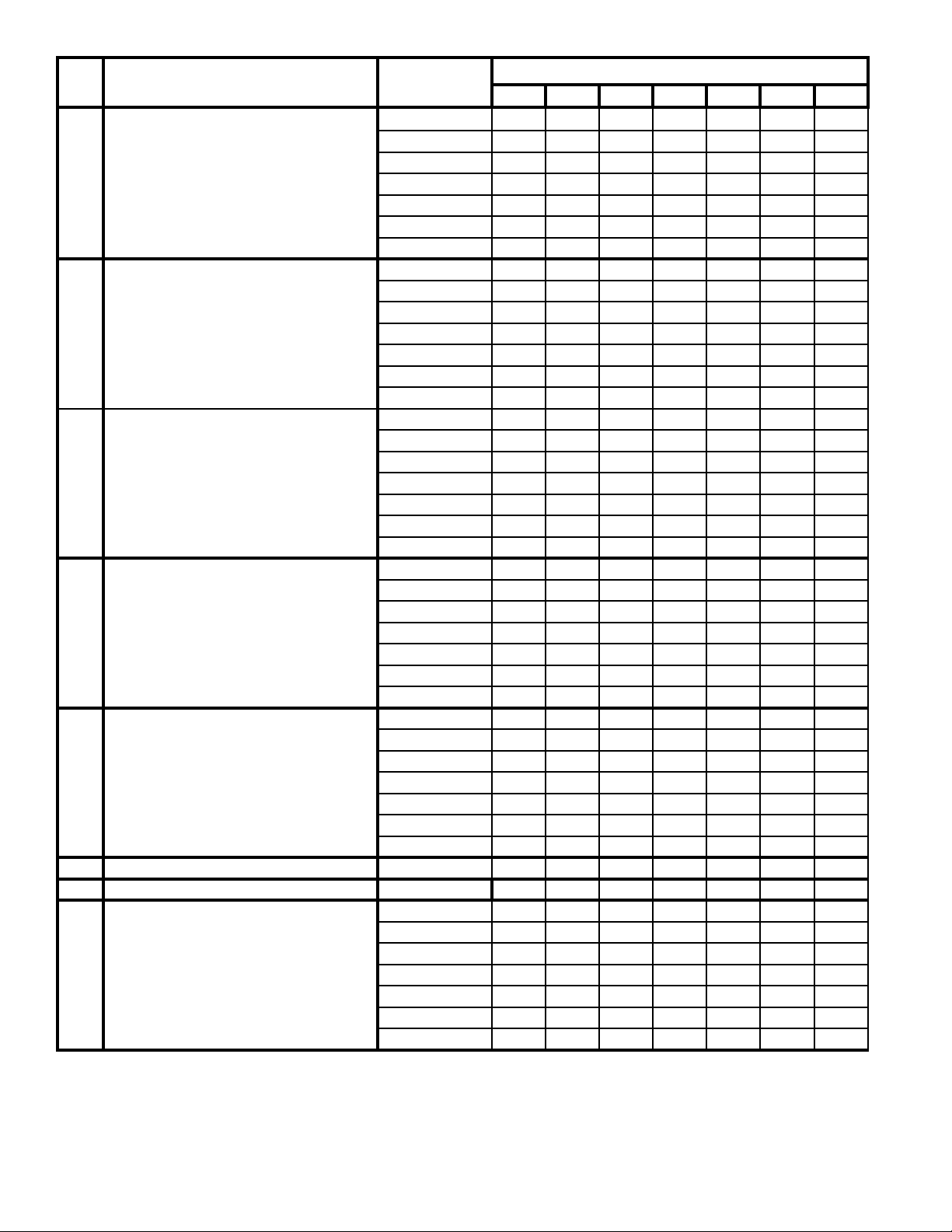
Key
No.
2A Base Wrapper
2B Base Tray
2C Burner Tray/Burner Tray Assembly
2D Base Front Panel
2E Burner Access Panel
2F Base Gasket Kit 6206002 1 1 1 1 1 1 1
2G Base Side Insulation 72007001 2 2 2 2 2 2 2
2H Base Rear Insulation
Description Part Number
30 40 50 60 70 80 90
71807031 1 --- --- --- --- --- ---
71807041 --- 1 --- --- --- --- ---
71807051 --- --- 1 --- --- --- ---
71807061 --- --- --- 1 --- --- ---
71807071 --- --- --- --- 1 --- ---
71807081 --- --- --- --- --- 1 ---
71807091 --- --- --- --- --- --- 1
102543-03 1 --- --- --- --- --- ---
102543-04 --- 1 --- --- --- --- ---
102543-05 --- --- 1 --- --- --- ---
102543-06 --- --- --- 1 --- --- ---
102543-07 --- --- --- --- 1 --- ---
102543-08 --- --- --- --- --- 1 ---
102543-09 --- --- --- --- --- --- 1
61807031 1 --- --- --- --- --- ---
61807041 --- 1 --- --- --- --- ---
61807051 --- --- 1 --- --- --- ---
61807061 --- --- --- 1 --- --- ---
61807071 --- --- --- --- 1 --- ---
61807081 --- --- --- --- --- 1 ---
61807091 --- --- --- --- --- --- 1
102705-03 1 --- --- --- --- --- ---
102705-04 --- 1 --- --- --- --- ---
102705-05 --- --- 1 --- --- --- ---
102705-06 --- --- --- 1 --- --- ---
102705-07 --- --- --- --- 1 --- ---
102705-08 --- --- --- --- --- 1 ---
102705-09 --- --- --- --- --- --- 1
102707-03 1 --- --- --- --- --- ---
102707-04 --- 1 --- --- --- --- ---
102707-05 --- --- 1 --- --- --- ---
102707-06 --- --- --- 1 --- --- ---
102707-07 --- --- --- --- 1 --- ---
102707-08 --- --- --- --- --- 1 ---
102707-09 --- --- --- --- --- --- 1
72007031 1 --- --- --- --- --- ---
72007041 --- 1 --- --- --- --- ---
72007051 --- --- 1 --- --- --- ---
72007061 --- --- --- 1 --- --- ---
72007071 --- --- --- --- 1 --- ---
72007081 --- --- --- --- --- 1 ---
72007091 --- --- --- --- --- --- 1
CG-E MODEL
32
Page 33
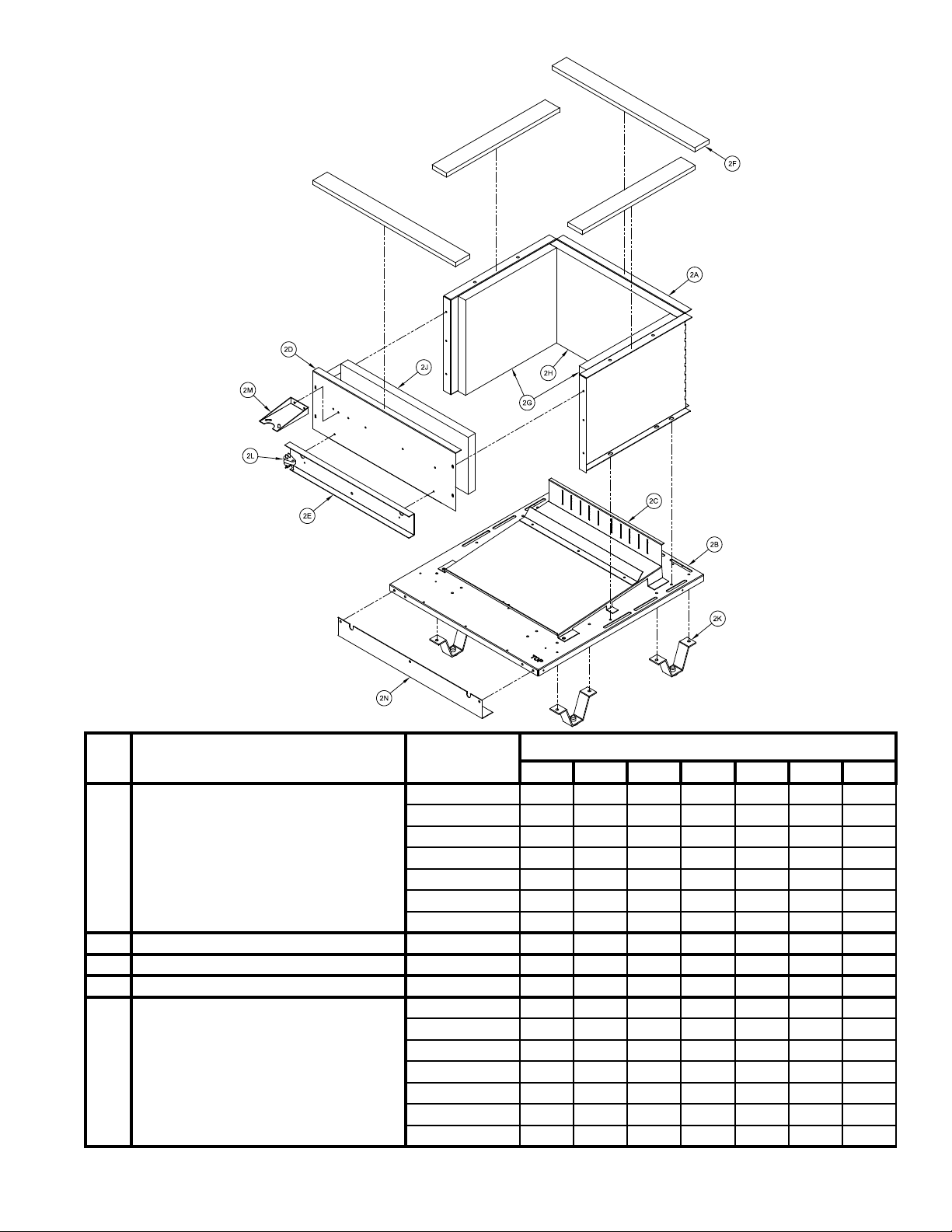
Key
No.
2J Base Front Insulation
2K Base Leg Assembly 6186001 4 4 4 4 4 4 4
2L Flame Roll-out Switch 80160044 1 1 1 1 1 1 1
2M Manifold Support Bracket 718070001 1 1 1 1 1 1 1
2N Front Air Dam
Description Part Number
30 40 50 60 70 80 90
72007032 1 --- --- --- --- --- ---
72007042 --- 1 --- --- --- --- ---
72007052 --- --- 1 --- --- --- ---
72007062 --- --- --- 1 --- --- ---
72007072 --- --- --- --- 1 --- ---
72007082 --- --- --- --- --- 1 ---
72007092 --- --- --- --- --- --- 1
103718-03 1 --- --- --- --- --- ---
103718-04 --- 1 --- --- --- --- ---
103718-05 --- --- 1 --- --- --- ---
103718-06 --- --- --- 1 --- --- ---
103718-07 --- --- --- --- 1 --- ---
103718-08 --- --- --- --- --- 1 ---
103718-09 --- --- --- --- --- --- 1
CG-E MODEL
33
Page 34
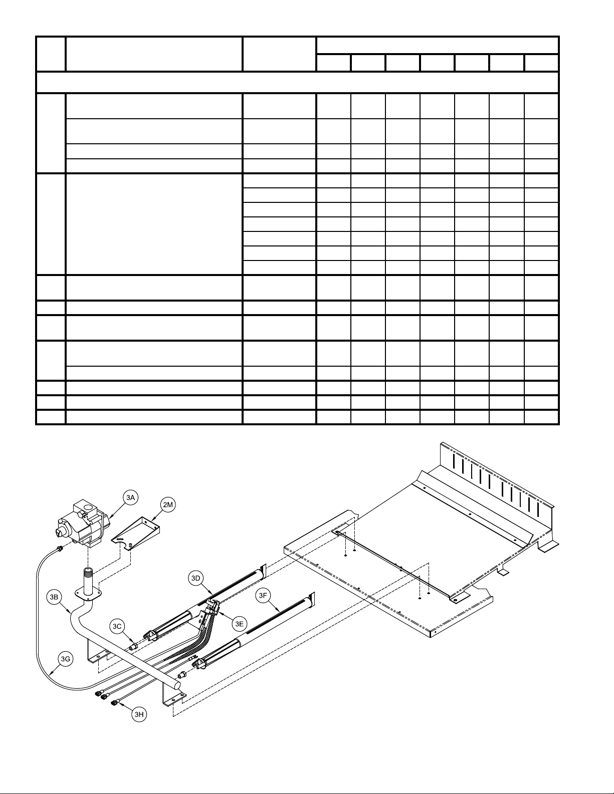
Key
No.
Description Part Number
Burners, Manifold and Gas Valve (Natural & LP Gas)
CG-E MODEL
30 40 50 60 70 80 90
Gas Valve, Honeywell VR8204P1171
(Nat. Gas)
Gas Valve, Honeywell VR8304P4496
3A
(Nat. Gas)
Gas Valve, Honeywell VR8204C3015 (LP) 81660146 1 1 1 1 --- --- ---
Gas Valve, Honeywell VR8304P4314 (LP) 81660160 --- --- --- --- 1 1 1
3B Manifold
Main Burner Orice #47 (White)
3C
(Nat. Gas)
3C Main Burner Orice 1.20 mm (LP) 822792 4 6 8 10 12 14 16
Main Burner w/60° Pilot Bracket -
3D
EI, Natural & LP Gas
Pilot Assy, Honeywell Q3452B2100
(Nat. Gas)
2E
Pilot Assy, Honeywell Q3452B2118 (LP) 102593-01 1 1 1 1 1 1 1
3F Main Burner w/Slotted Orice Bracket 100146-01 3 5 7 9 11 13 15
3G Pilot Tubing 1/4" OD x 30" Lg. Aluminum 8236122 1 1 1 1 1 1 1
3H Ground Wire Assembly 103776-01 1 1 1 1 1 1 1
81660282 1 1 1 1 --- --- ---
81660283 --- --- --- --- 1 1 1
82207031 1 --- --- --- --- --- ---
82207041 --- 1 --- --- --- --- ---
82207051 --- --- 1 --- --- --- ---
82207061 --- --- --- 1 --- --- ---
82207071 --- --- --- --- 1 --- ---
82207081 --- --- --- --- --- 1 ---
82207091 --- --- --- --- --- --- 1
822710 4 6 8 10 12 14 16
100147-01 1 1 1 1 1 1 1
102592-01 1 1 1 1 1 1 1
34
Page 35
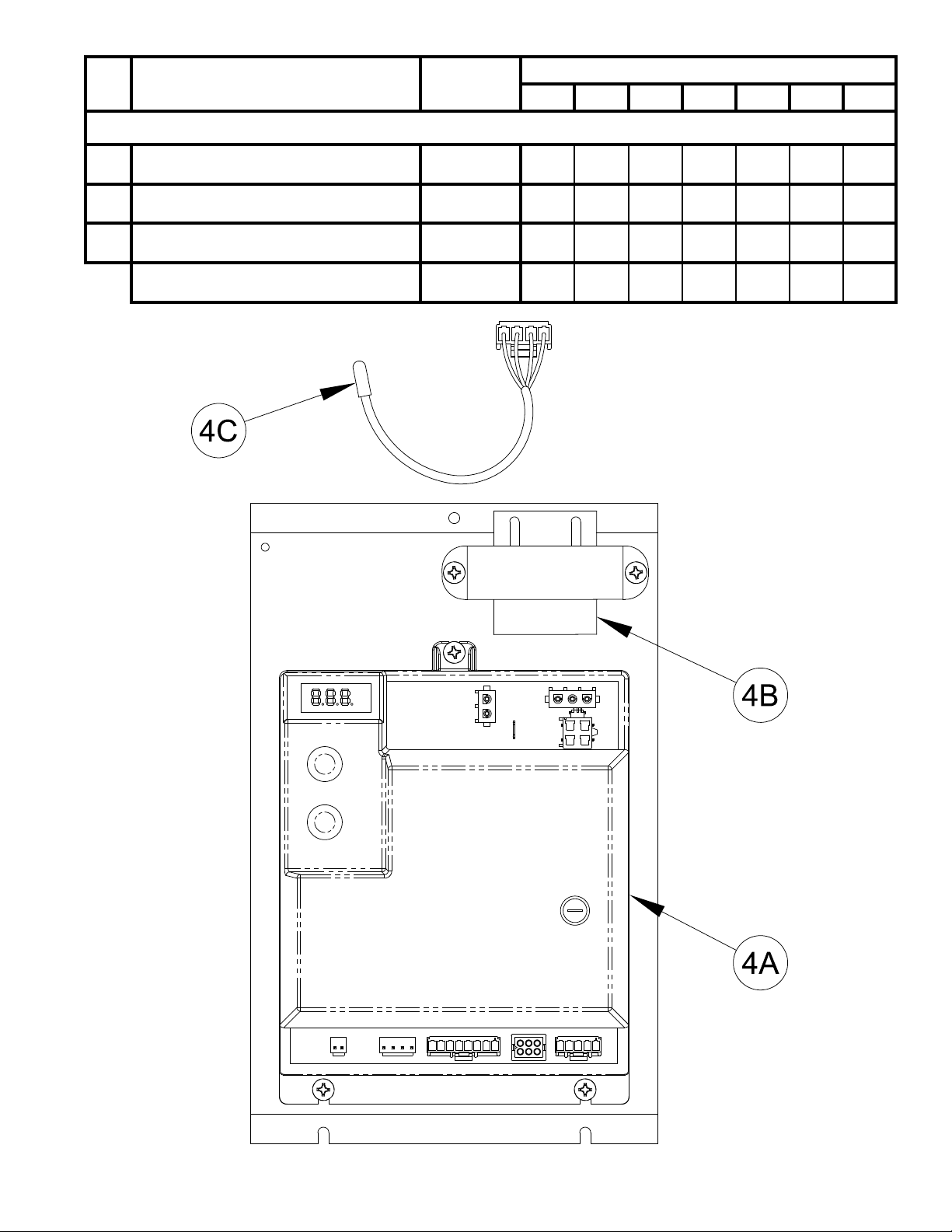
Key
No.
Description Part Number
Controls
Boiler Control, Atmospheric Draft,
4A
UTEC 1135-630
Transformer, 40 VA, modied Honeywell
4B
AT140B1297
Limit Rated Temperature Sensor, 12" Lg.,
4C
Tasseron
Temperature Sensor Clip, Honeywell
32002656-001 (not shown)
CG-E MODEL
30 40 50 60 70 80 90
106541-01 1 1 1 1 1 1 1
106529-01 1 1 1 1 1 1 1
106643-01 1 1 1 1 1 1 1
102422-01 1 1 1 1 1 1 1
35
Page 36
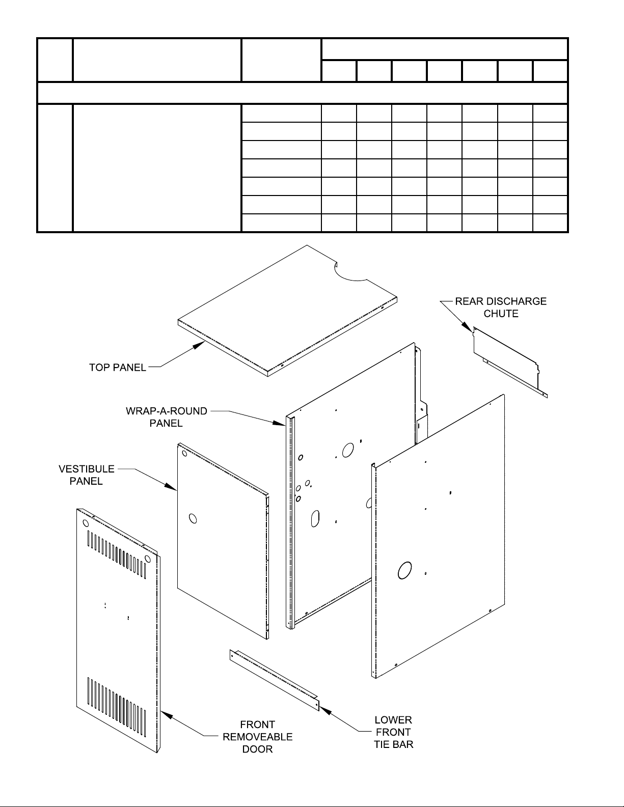
Key
No.
Description Part Number
Jacket Assembly, Complete
CG-E MODEL
30 40 50 60 70 80 90
106707-03 1 --- --- --- --- --- ---
106707-04 --- 1 --- --- --- --- ---
106707-05 --- --- 1 --- --- --- ---
5 Jacket Assembly, Complete
106707-06 --- --- --- 1 --- --- ---
106707-07 --- --- --- --- 1 --- ---
106707-08 --- --- --- --- --- 1 ---
106707-09 --- --- --- --- --- --- 1
36
Page 37
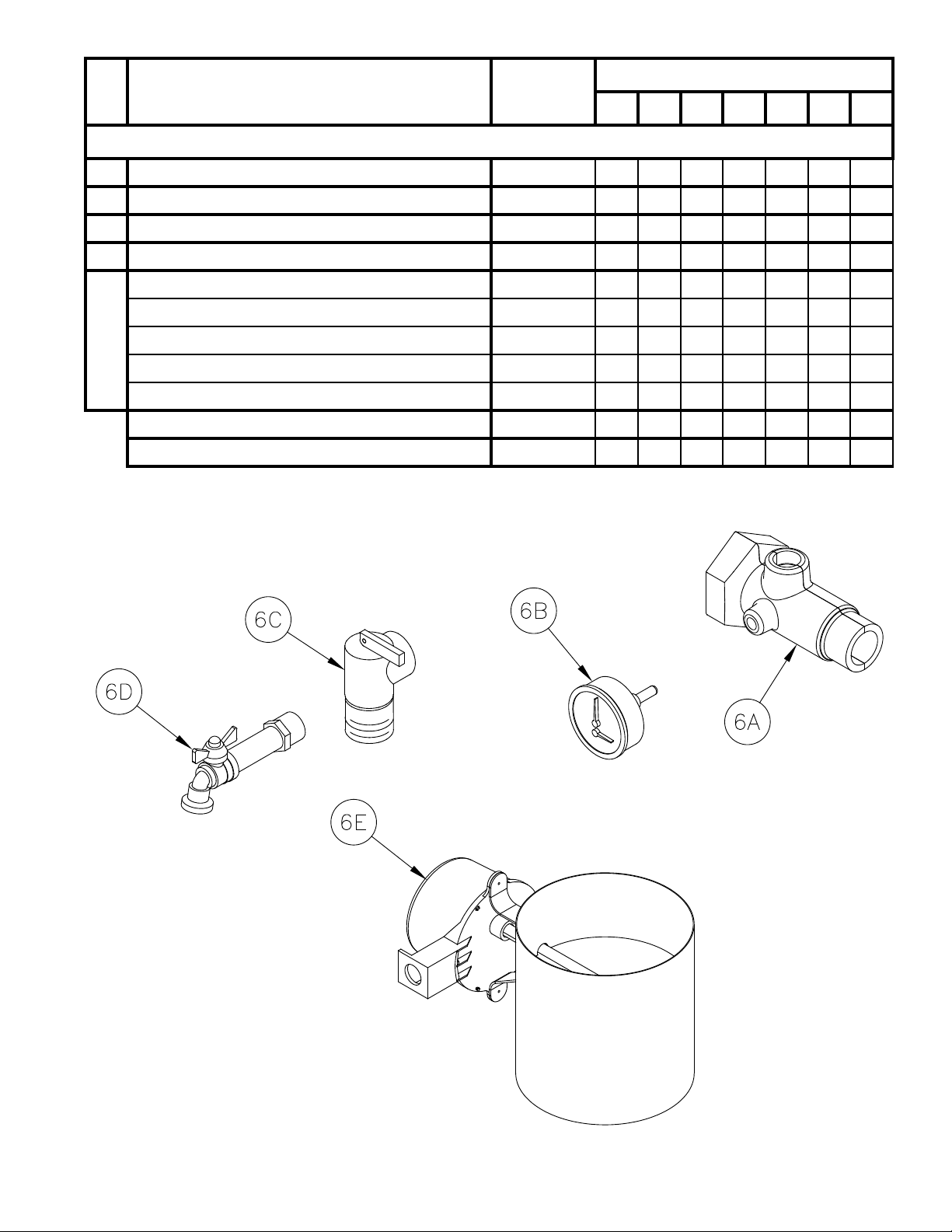
Key
No.
Description Part Number
30 40 50 60 70 80 90
CG-E MODEL
Trim and Vent Damper
6A Supply Water Manifold 8060700 1 1 1 1 1 1 1
6B Temperature / Pressure Gauge 100282-01 1 1 1 1 1 1 1
6C Safety Relief Valve, 30 psi 81660363 1 1 1 1 1 1 1
6D Drain Valve 102802-01 1 1 1 1 1 1 1
Vent Damper - 4" Dia. 102284-01 1 --- --- --- --- --- ---
Vent Damper - 5" Dia. 102284-02 --- 1 --- --- --- --- ---
6E
Vent Damper - 6" Dia. 102284-03 --- --- 1 1 --- --- ---
Vent Damper - 7" Dia. 102284-04 --- --- --- --- 1 1 ---
Vent Damper - 8" Dia. 102284-05 --- --- --- --- --- --- 1
Circulator, Taco 007 (not shown) 8056170 1 1 1 1 1 1 1
Circulator, Grundfos UP-15 (not shown) 105654-01 1 1 1 1 1 1 1
37
Page 38
383940
Page 39
Page 40
 Loading...