

Page 1
CENTRIFUGAL FANS
AcF/PLR, AF, BC, BC Pressure Blowers, EcF Plenum, RTS, HPBC
WORD ABOUT SAFETY
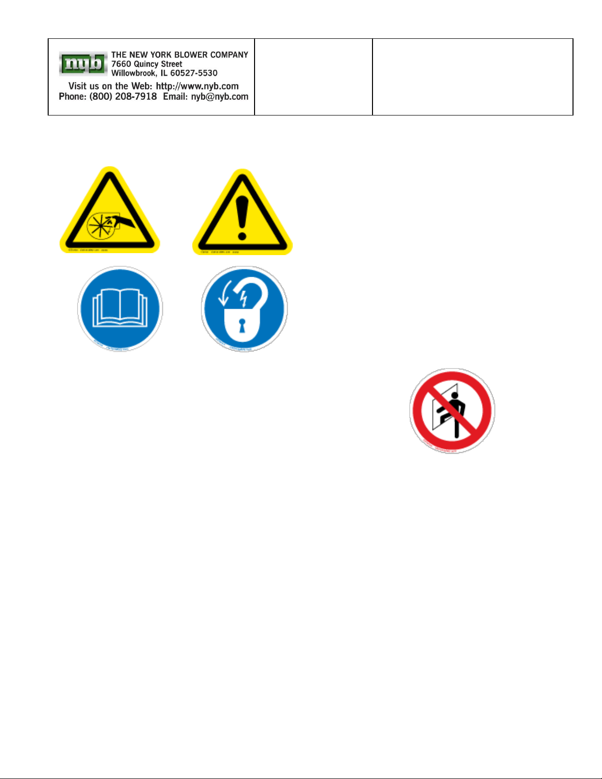
Beginning in June 2012, the above WARNING signage has been
placed on all nyb fans, as specified by ISO and recommended by
the European Union. Air moving equipment involves electrical
wiring, moving parts, sound, and air velocity or pressure which
can create safety hazards if the equipment is not properly
installed, operated and maintained. To minimize this danger,
follow these instructions as well as the additional instructions and
warnings on the equipment itself.
All installers, operators and maintenance personnel should study
AMCA Publication 410, "Recommended Safety Practices for Air
Moving Devices", which is included as part of every shipment.
Additional copies can be obtained by writing to New York Blower
Company, 7660 Quincy St., Willowbrook, IL 60527.
ELECTRICAL DISCONNECTS
Every motor driven fan should have an independent disconnect
switch to isolate the unit from the electrical supply. It should be
near the fan and must be capable of being locked by maintenance personnel while servicing the unit, in accordance with
OSHA procedures.
MOVING PARTS
All moving parts must have guards to protect personnel. Safety
requirements vary, so the number and type of guards needed to
meet company, local and OSHA standards must be determined
and specified by the user. Never start a fan without having all
safety guards installed. Check regularly for damaged or missing
guards and do not operate any fan with guards removed. Fans
can also become dangerous because of potential “windmilling”,
even though all electrical power is disconnected. Always block
the rotating assembly before working on any moving parts.
SOUND
Some fans can generate sound that could be hazardous to
exposed personnel. It is the responsibility of the system
designer and user to determine sound levels of the system,
the degree of personnel exposure, and to comply with
applicable safety requirements to protect personnel from
excessive noise. Consult nyb for fan sound power level
ratings.
AIR PRESSURE AND SUCTION
In addition to the normal dangers of rotating machinery, fans
present another hazard from the suction created at the fan
inlet. This suction can draw materials into the fan where they
become high velocity projectiles at the outlet. It can also be
extremely dangerous to persons in close proximity to the
inlet, as the forces involved can overcome the strength of
most individuals. Inlets and outlets that are not ducted should
be screened to prevent entry and discharge of solid objects.
Danger: Do Not Enter/Confined Space
ACCESS DOORS
The above DANGER decal is placed on all nyb cleanout
doors. These doors, as well as access doors to the duct
system, should never be opened while the fan is in operation.
Serious injury could result from the effects of air pressure or
suction.
Quick-opening doors must have the door handle bolts
securely tightened to prevent accidental or unauthorized
opening. Bolted doors must be tightened for the same reason.
RECEIVING AND INSPECTION
The fan and accessories should be inspected on receipt for
any shipping damage. Turn the wheel by hand to see that it
rotates freely and does not bind. If dampers or shutters are
provided, check these accessories for free operation of all
moving parts.
F.O.B. factory shipping terms require that the receiver be
responsible for inspecting the equipment upon arrival. Note
damage or shortages on the Bill of Lading and file any claims
for damage or loss in transit. nyb will assist the customer as
much as possible; however, claims must be originated at the
point of delivery.
INSTALLATION
MAINTENANCE,
OPERATING
INSTRUCTIONS
IM-100
Page 2
Page 2
HANDLING
Fans should be lifted by the base, mounting supports, or
lifting eyes/lugs only. Never lift a fan by the wheel, shaft,
motor, motor bracket, housing inlet, outlet, or any fan part
not designed for lifting. A spreader should be used to avoid
damage.
On direct drive Arrangement 7 or 8 fans, lifting holes are provided in the motor base to assist in handling the fan
assembly. These lifting holes should be used in conjunction
with the lifting eyes/lugs when lifting and positioning the fan
onto its foundation. A heavy round steel bar or appropriate
fixture can be passed through the lifting holes to simplify
attachment of the lifting device. Be sure to follow all local
safety codes when moving heavy equipment.
STORAGE
Whenever possible, fans and accessories should be stored in
a clean, dry location to prevent rust and corrosion of steel
components. If outdoor storage is necessary, protection
should be provided. Cover the inlet and outlet to prevent the
accumulation of dirt and moisture in the housing. Cover
motors with water-proof material. Remove any fan and
motor drain plugs to minimize moisture buildup. Refer to
motor manufacturer’s IM manual for further motor storage
instructions.
Any stored bearing can be damaged by condensation
caused by temperature variations. Therefore, nyb fan
bearings are filled with grease at the factory to exclude
air and moisture. Such protection is adequate for
shipment and subsequent immediate installation and
operation.
For long term or outdoor storage, mounted bearings
should be immediately regreased and wrapped with
plastic for protection. Split housed bearings may require
additional grease to completely fill the bearing housing
cavity. Rotate the fan wheel and motor shaft by hand
at least every two weeks to redistribute grease on
internal bearing parts. Each month the fan and motor
bearings should be purged with new grease to remove
condensation, since even a filled bearing can accumulate
moisture. Use caution when purging, as excessive
pressure can damage the seals. Rotate the shaft while
slowly adding grease.
For Belt-Driven units, belts should be slackened to
prevent damage to shaft, belts, and bearings.
Check shutters for free operation and lubricate moving parts
prior to storage. Inspect the stored unit periodically to ensure
the above precautionary storage measures are still in tact.
Prior to start-up, split housed bearings should have excess
grease removed such that the grease level is level with the
bottom of the shaft.
FAN INSTALLATION
nyb wheels are dynamically balanced when fabricated. Fully
assembled fans are test run at operating speeds to check
the entire assembly for conformance to nyb vibration limits.
Nevertheless, all units must be adequately supported for
smooth operation. Ductwork or stacks should be indepen-
dently supported as excess weight may distort the fan
housing and cause contact between moving parts. nyb
recommends using flexible connections at the inlet and
outlet to prevent vibration transmission from the fan to
the system and vice versa. Flexible connectors also
eliminate loading issues stemming from thermal expansion in
systems with high temperature air streams. Where vibration
isolators are used, consult the nyb certified drawing for
proper location and adjustment.
Slab-Mounted Units
A correctly designed and level concrete foundation provides
the best means of installing floor-mounted fans. The mass of
the base must maintain the fan/driver alignment, absorb
normal vibration, and resist lateral loads. The overall
dimensions of the concrete base should extend at least six
inches beyond the base of the fan. The weight of the slab
should be approximately three times the weight of the total
fan assembly weight, including the motor. The foundation
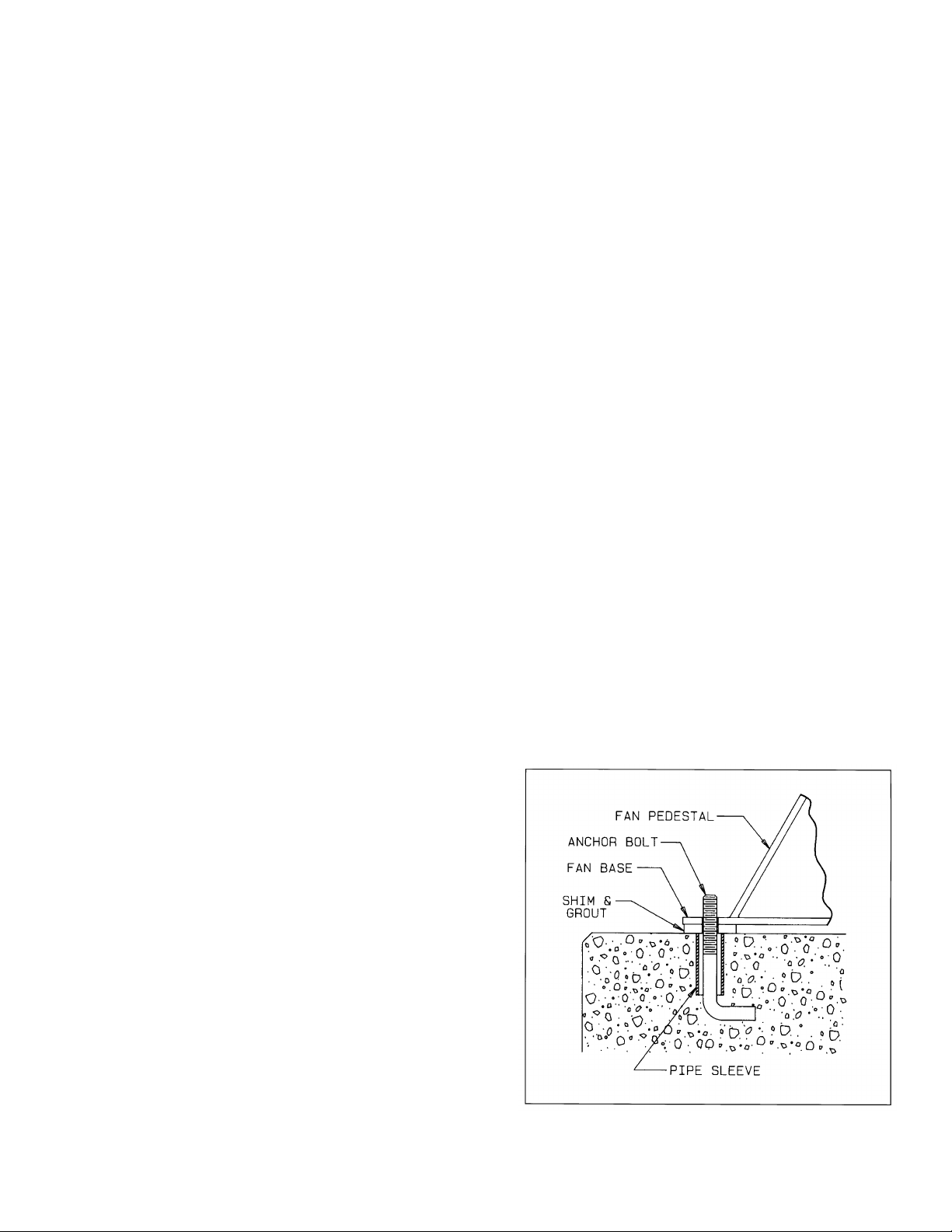
requires firmly anchored fasteners such as the anchor bolts
shown in Figure 1. Hammer-drilled expansion fasteners can
be used in less demanding applications.
Move the fan to the mounting location and lower it over the
anchor bolts, leveling and supporting the fan base with shims
at each bolt hole location. Fasten the fan securely, ensuring
that the fan base is not put into a bind when tightening
anchor bolts. This may cause distortion that can be
transferred to the bearing housings, causing excessive
vibration and premature bearing failure. You should consider
grouting in fans sized 40 and larger. When grout is used,
shim the fan at least 3/4-inch from the concrete base. Do not
rely on grout to support the fan structure. (See Figure 1.)
When isolation is used, check the nyb certified drawing for
installation instructions.
Elevated Units
When an elevated or suspended structural steel platform is
used, it must have sufficient bracing to support the unit load
and prevent side sway. A poorly designed support structure
can experience resonance triggered by the fan operating
speed. The platform should be of welded construction to
maintain permanent alignment of all members.
Figure 1
Page 3
Page 3
V-BELT DRIVE
Installation
1. Remove all foreign material from the fan and motor shafts.
Coat shafts with machine oil for easier mounting. Mount
the belt guard backplate at this time if partial installation is
required prior to sheave mounting.
2. Mount sheaves on shafts after checking sheave bores and
bushings for nicks or burrs. Avoid using force. If resistance
is encountered, lightly polish the shaft with emery cloth
until the sheave slides on freely. Tighten tapered bushing
bolts sequentially so that equal torque is applied to each.
3. Adjust the motor on its base to a position closest to the fan
shaft. Install belts by working each one over the sheave
grooves until all are in position. Never pry the belts into
place. On nyb packaged fans, sufficient motor adjustment is
provided for easy installation of the proper size belts.
Warning: Do not rotate sheaves by grabbing belts by
hand.
4. Adjust sheaves and the motor shaft angle so that the
sheave faces are in the same plane. Check this by placing a
straightedge across the faces of the sheaves. Any gap
between the edge and sheave faces indicates misalignment. Important: This method is only valid when the width of
the surface between the belt edge and the sheave face is
the same for both sheaves. When they are not equal, or
when using adjustable-pitch sheaves, adjust so that all
belts have approximately equal tension. Both shafts should
be at right angles to the center belt.
Belt Tensioning
1. Check belt tension with a tensioning gage and adjust using
the motor slide base. Excess tension shortens bearing life
while insufficient tension shortens belt life, this can reduce
fan performance and may cause vibration. The lowest
allowable tension is that which prevents slippage under full
load. Belts may slip during start-up, but slipping should
stop as soon as the fan reaches full speed. For more
precise tensioning methods, consult the drive
manufacturer’s literature.
2. Recheck setscrews, rotate the drive by hand and check for
rubbing, then complete the installation of the belt guard
3. Belts tend to stretch somewhat after installation. Recheck
tension after several days of operation. Check sheave
alignment as well as setscrew and/or bushing bolt tightness.
COUPLING
Coupling alignment should be checked after permanent
installation and prior to start up. Alignment is set at the factory,
but shipping, handling, and installation can cause
misalignment. Also check for proper coupling lubrication. For
details on lubrication and for alignment tolerances on the
particular coupling supplied, see the manufacturer's installation
and maintenance supplement in the shipping envelope
Installation
Most nyb fans are shipped with the coupling installed. In cases
where the drive is assembled after shipping, install the coupling
as follows:
1. It is recommended to wait until the fan is permanently
installed before beginning the coupling alignment process
in order to prevent possible misalignment during fan
installation.
2. Remove all foreign material from fan and motor shafts and
coat with machine oil for easy mounting of coupling halves.
3. Mount the coupling halves on each shaft, setting the gap
between the faces specified by the manufacturer. Avoid
using force. If mounting difficulty is encountered, lightly
polish the shaft with emery cloth until the halves slide on
freely.
Alignment
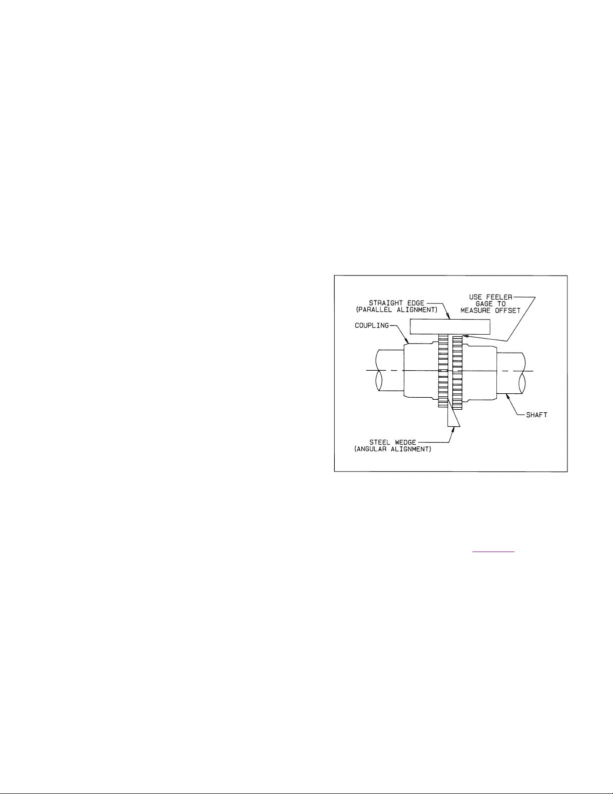
1. Align the coupling to within the manufacturer's limits for
parallel and angular misalignment (see Figure 2). A dial
indicator or laser can also be used for alignment where
greater precision is desired. Adjustments should be made
by moving the motor to change shaft angle, and by the use
of foot shims to change motor shaft height. Do not move
the fan shaft or bearing.
2. When correctly aligned, install the flexible element and
tighten all fasteners in the coupling and motor base.
Lubricate the coupling if necessary.
3. Recheck alignment and gap after a short period of operation, and recheck the tightness of all fasteners in the coupling assembly.
4. .
START-UP
A start-up checklist is available on nyb’s Maintenance manuals
page under the support tools menu, Click Here. Safe operation
and maintenance includes the selection and use of appropriate
safety accessories for the specific installation. This is the
responsibility of the system designer and requires consideration
of equipment location and accessibility as well as adjacent
components. All safety accessories must be installed properly
prior to start-up.
Safe operating speed is a function of system temperature and
wheel design. Do not under any circumstances exceed the
maximum safe fan speed published in your nyb certified
drawing package, which is available from your nyb field sales
representative.
Procedure
1. If the drive components are not supplied by nyb, verify with
the manufacturer that the starting torque is adequate for
the speed and inertia of the fan.
Figure 2
Page 4
Page 4
2. Inspect the installation prior to starting the fan. Check for
any loose items or debris that could be drawn into the fan
or dislodged by the fan discharge. Check the interior of the
fan as well. Turn the wheel by hand to check for binding.
3. Check drive installation and belt tension.
4. Check the tightness of all setscrews, nuts and bolts.
Ensure that anchor bolts are also properly torqued. When
furnished, tighten hub setscrews with the wheel oriented
so that the setscrew is positioned underneath the shaft.
5. Install all remaining safety devices and guards. Verify that
the supply voltage is correct and wire the motor. “Bump”
the starter to check for proper wheel rotation.
6. Check to ensure that neither the fan nor motor shaft are
rotating.
7. “Bump” the starter to check for proper wheel rotation.
8. Use extreme caution when testing the fan with ducting disconnected. Apply power and check for unusual sounds or
excessive vibration. If either exists, see the section on
Common Fan Problems. To avoid motor overload, do not
run the fan for more than a few seconds if ductwork is not
fully installed. Without the ductwork attached, normal operating speed may not be obtained without motor overload.
Once ductwork is attached, check for correct fan speed
and complete installation. Ductwork and guards must be
fully installed for safety.
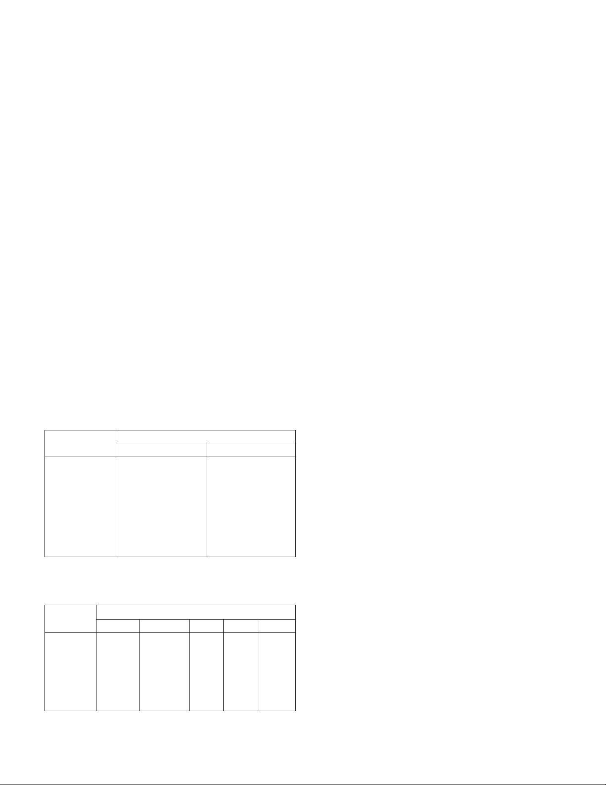
9. All wheel, sheave, and coupling setscrews should be
rechecked after a few minutes, eight hours and two weeks
of operation (see Tables 1 & 2 for correct tightening
torques).
NOTE: Shut the fan down immediately if there is any
sudden increase in fan vibration.
Fan Shutoff for Fans with Elevated Airstream
Temperatures (Greater than 200 °F)
High temperature, rotating equipment such as fans must be
protected from “heat soaking”. Fan wheels must be rotating
whenever the airstream temperature is above 200°F. to
prevent the shaft from “sagging” causing a permanent bend in
the shaft. After the airstream temperature has fallen below
200°F, the fan can be shutdown. Start-up and shut down
procedures are required to prevent this. If a power failure
occurs, rotate the shaft manually if necessary.
If a shaft is bent due to heat soaking or binding a sudden
increase in fan vibration will occur. The shaft will need to be
removed, checked for straightness and straightened or
replaced.
FAN MAINTENANCE
nyb fans are manufactured to high standards with quality mate-
rials and components. Proper maintenance will ensure a long
and trouble-free service life. Do not attempt any maintenance
on a fan unless the electrical supply has been completely
disconnected and locked out. In many cases, a fan can
windmill despite removal of all electrical power. The rotating
assembly should be blocked securely before attempting
maintenance of any kind.
The key to good fan maintenance is regular and systematic
inspection of all fan parts. Inspection frequency is determined by
the severity of the application and local conditions. Strict
adherence to an inspection schedule is essential.
Regular fan maintenance should include the following:
1. Check the fan wheel for any wear or corrosion, as either
can cause catastrophic failures. Check also for the build-up
of material, which can cause unbalance resulting in
vibration, bearing wear and serious safety hazards. Clean
or replace the wheel as required.
2. Check the V-belt drive for proper alignment and tension
(see section on V-belt drives). If belts are worn, replace
them as a set, matched to within manufacturer’s tolerances.
Lubricate the coupling of direct-drive units and check for
alignment (see section on couplings).
3. Lubricate the bearings, but do not over lubricate (see the
bearing section for detailed specifications).
4. Ceramic-felt shaft seals require no maintenance, although
worn seals should be replaced. When lip-type shaft seals
are provided, lubricate them with "NEVER-SEEZ" or other
anti-seize compound. Schedule in accordance with the
bearing lubrication table on page 5.
WARNING: Do not remove or loosen the fan hub from the
fan wheel. Removing or loosening the fan hub from the fan
wheel will cause imbalance and void the warranty.
5. During any routine maintenance, all setscrews and bolts
should be checked for tightness. See the corresponding
table for correct torques.
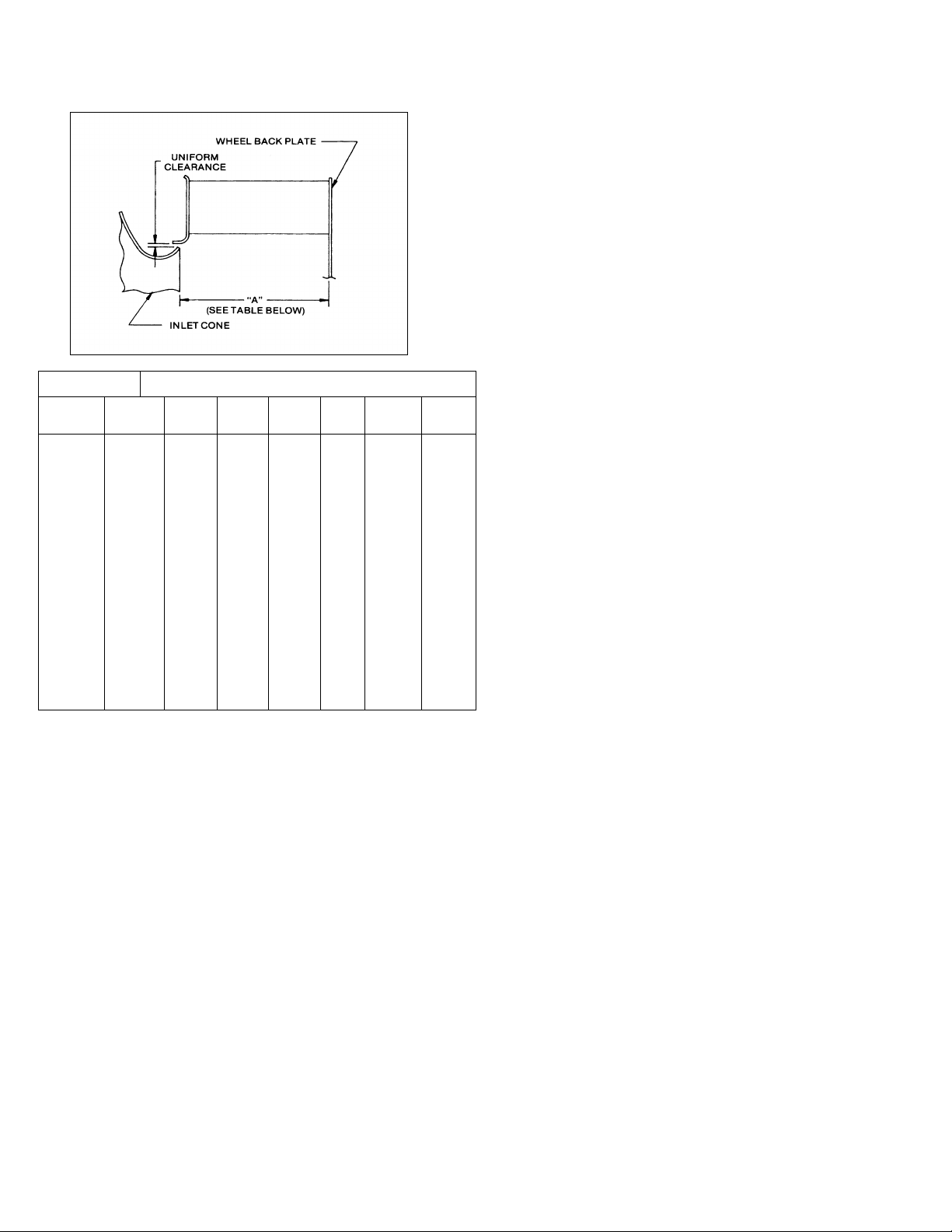
6. When installing a new wheel or cone, the proper wheel-toinlet cone clearance must be maintained (see Figure 3 for
correct full-width wheel dimensions) (Dims. for narrow
width wheels will vary)
Setscrew
Manufacturer
Diameter
Link-Belt
Sealmaster
SKF
McGill
Dodge
#10
40
--
35
35
--
1/4
90
65
50
85
--
5/16
185
125
165
165
160
3/8
325
230
290
290
275
7/16
460
350
350
--
--
1/2
680
500
620
--
600
5/8
1350
1100
1325
--
1200
3/4
2350
--
--
--
2000
Table 1 - WHEEL SETSCREW TORQUES
Setscrew Size
Carbon Steel Setscrew Torque*
Diameter (in.)
lb.-in.
lb.-ft.
1/4
75
6.2
5/16
144
12
3/8
252
21
7/16
396
33
1/2
600
50
5/8
1164
97
3/4
2016
168
7/8
3204
267
1
4800
400
Table 2 – BEARING SETSCREW TORQUE, lb.-in.
Note: Split pillow block bearing are fixed to the shaft
with tapered sleeves and generally do not have
setscrews.
* Stainless Steel setscrews are not hardened and should
not be tightened to more than 1/2 the values shown.
Page 5
Page 5
Figure 3
WHEEL BALANCE
Airstreams containing particulate or chemicals can cause abrasion or corrosion of the fan parts. This wear is often uneven and
can lead to significant wheel imbalance over time. When such
wear is discovered, a decision must be made as to whether to
rebalance or replace the wheel.
The soundness of all parts should be determined if the original
thickness of components is reduced. Be sure there is no hidden
structural damage. The airstream components should also be
cleaned to remove any build-up of foreign material. Specialized
equipment can be used to rebalance a cleaned wheel that is
considered structurally sound.
Balance weights should be rigidly attached at a point that will not
interfere with the housing nor disrupt airflow. Remember that
centrifugal forces can be extremely high at the outer radius of a
fan wheel. Welding is the preferred method of balance weight
attachment. Be sure to ground the welder directly to the fan
wheel. Otherwise, the welding current could pass through the
fan bearings and damage them.
BEARINGS
Storage
Any stored bearing can be damaged by condensation
caused by temperature variations. Therefore, nyb fan
bearings are filled with grease at the factory to exclude
air and moisture. Such protection is adequate for
shipment and subsequent immediate installation and
operation.
For long term or outdoor storage, mounted bearings
should be immediately regreased and wrapped with
plastic for protection. Split housed bearings may require
additional grease to completely fill the bearing housing
cavity. Rotate the fan wheel and motor shaft by hand
at least every two weeks to redistribute grease on
internal bearing parts. Each month the fan and motor
bearings should be purged with new grease to remove
condensation, since even a filled bearing can accumulate
moisture. Use caution when purging, as excessive
pressure can damage the seals. Rotate the shaft while
slowly adding grease.
Operation
Check the setscrew torque before start-up (see
corresponding table for correct values). Since bearings are
completely filled with grease at the factory, they may run at
an elevated temperature during initial operation. Surface
temperatures may reach 180°F. and grease may bleed
from the bearing seals. This is normal and no attempt
should be made to replace lost grease. Bearing surface
temperatures will decrease when the internal grease
quantity reaches a normal operating level. Relubrication
should follow the recommended schedule.
Lubrication
Use the table for relubrication scheduling according to
operating speed and shaft diameter. Fan bearings should
be lubricated with a premium quality lithium-based grease
conforming to NLGI Grade 2. Examples are:
Mobil - Mobilgrease XHP 222 Exxon - Ronex MP
Mobil - Unirex N2 Shell - Gadus S2 V220
Mobil - SHC100
These greases are for fan bearing surface temperatures of
40°F. to 180°F. For surface temperatures of 181°F. to
230°F. use Mobilith SHC220. Do not use “high
temperature” greases, as many are not formulated to be
compatible with fan bearings.
Add grease to the fan bearings while running the fan or
rotating the shaft by hand. Be sure all guards are in place
if lubrication is performed while the fan is operating. Add
just enough grease to cause a slight purging at the seals
except on split pillowblocks. Completely filled fan bearings
will run hotter until a sufficient amount of grease is purged
out of the seals.
Split pillowblock bearings (Link-Belt P-LB6800 & PLB6900, SKF SAF 22500, Dodge SAF-XT) should be
cleaned and repacked at approximately every eighth
lubrication interval. This requires removal of the bearing
cap. Clean out old grease and repack the bearing with
fresh grease. Pack the bearing fully and fill the housing
reservoir to the bottom of the shaft on both sides of the
bearing. Replace the bearing cap, being careful not to mix
caps, as they are not interchangeable from one bearing to
another. Do not over lubricate split pillowblock
bearings.
Refer to your motor manufacturer’s installation and
maintenance manual for motor bearing lubrication
information.
Fan Size
“A” Dimension [inches]
AcF/PLR,
BC, EcF
Plenum
AF, HPBC,
RTS
AcF/PLR
AF
BC
RTS
HPBC
EcF
Plenum
10
--
3 1/2
--
--
--
--
--
12
--
4 1/2
--
--
--
--
4 5/8
15
--
5 1/2
--
--
--
--
5 7/8
18
24 7 7 1/4
--
--
4 7/8
7 1/2
22
27
8 1/4 8 --
6 7/8
5 3/8
8 7/8
24
30
9 1/4
9
9 3/16
7 5/8 6 10 1/8
27
33
10 1/8
9 3/4
10 1/8
8 3/8
6 9/16
10 7/8
30
36
11 1/4
10 7/8
11 3/16
9 3/8
7 1/4
12
33
40
12 1/4
12
12 5/16
10 1/2
8
13 1/8
36
44
13 3/8
13 1/4
13 5/8
11 5/8
8 7/8
14 1/2
40
49
14 3/4
14 5/8
15 1/16
12 7/8
9 3/4
15 7/8
44
54
16 1/4
16 1/8
16 5/8
14 1/4
10 13/16
17 3/8
49
60
17 7/8
17 3/4
18 5/16
15 3/4
11 15/16
19 1/4
54
66
19 3/4
19 5/8
20 1/4
17 3/8
13 1/8
21 1/8
60
73
21 3/4
21 3/4
22 3/8
19 1/4
14 9/16
23 1/4
66
80
24
24
24 5/8
20 7/8
16 1/16
25 5/8
73
--
26 1/2
27 1/4
27 1/4
23 1/4
17 3/4
27 5/8
80
--
28 3/4
30 1/8
30 1/8
--
--
--
89
--
31 5/8
33 1/4
33 1/4
--
--
--
FULL WIDTH WHEEL CONE CLEARANCES
(contact nyb for partial width dimensions)
Page 6
Page 5
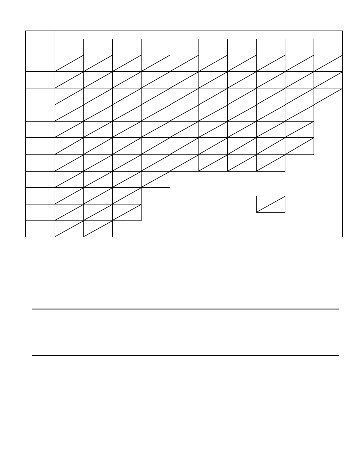
BEARING LUBRICATION INTERVAL (months)
Shaft
RPM
1-500
501-1000
1001-1500
1501-2000
2001-2500
2501-3000
3001-3500
3501-4000
4001-4500
4501-5000
5/8
Thru
1
6 6 6 5
2 6 2 6 2 4 1 4 1 4 1 2 1
13/16
thru
1 7/16
6 6 6
2.5 6 1.75 4 1.25 4 1 4 1/2 2 1/2 2 1/2 2 1/2 1 1/2
1 11/16
thru
1 15/16
6 6 6
2.5
4-6
1.5 4 1.14 4 3/4 2 1/2 2 1/2 2 1/2 1 1/2 1
2 3/16
6 6 6
2.25
4-6
1.25 4 3/4 2 1/2 2 1/2 1 1/2 1 1/2
1
2 7/16
6 4 4-6 2 4-6 1 4
3/4 2 1/2 2 1/2 1 1/2
1
1
2 11/16
&
2 15/16
5 4 4 2 2-4 1 2
3/4 2 1/2 1 1/2
1
1
1
3 7/16
thru
4 3/16
4 4 4 2 2-4 1 1
1/2
2 1
1
1
4 7/16
4 4 4 1 2
1/2
1
Ball Bearings & Split Pillowblock
Spherical Roller Bearings
4 15/16
4 2 4 1 2
1/2
5 7/16
6 4 2
Non-Split Pillowblock Spherical
Roller Bearings
6
6 4
Note:
1. These are general recommendations only; specific
manufacturer’s recommendations may vary slightly.
2. Assumes clean environment, -20°F. to 120°F.
a. Consult The New York Blower Company for operation
below -20°F. ambient.
b. Ambient temperature greater than 120°F. will shorten
bearing life.
c. Under extremely dirty conditions, lubricate more
frequently.
3. Assumes horizontal mounting configuration. For vertically
mounted applications, lubricate twice as frequently.
Government Warnings
Disposal of material should be made in accordance to local government regulations.
California Prop 65 – WARNING: This product contains a chemical known to the state of California to cause cancer and/or
birth defects or other reproductive harm.
Page 7

The New York Blower Company – 7660 Quincy Street – Willowbrook, Illinois 60527-5530
Page 6
COMMON FAN PROBLEMS
Excessive Vibration
A common complaint regarding industrial fans is “excessive
vibration”. nyb is careful to ensure that each unit is precisely
balanced prior to shipment; however, there are many other
causes of vibration including:
1. Loose mounting bolts, setscrews, bearings or couplings.
2. Misalignment or excessive wear of couplings or
bearings.
3. Misaligned or unbalanced motor.
4. Bent shaft due to mishandling or material impact.
5. Accumulation of foreign material on the wheel.
6. Excessive wear or erosion of the wheel.
7. Excessive system pressure or restriction of airflow due
to closed dampers.
8. Inadequate structural support, mounting procedures or
materials.
9. Externally transmitted vibration.
Inadequate Performance
1. Incorrect testing procedures or calculations.
2. Fan running too slowly.
3. Fan wheel rotating in wrong direction or installed
backwards on shaft.
4. Wheel not properly centered relative to inlet cone.
5. Damaged or incorrectly installed cut off sheet or
diverter.
6. Poor system design, closed dampers, air leaks, clogged
filters, or coils.
7. Obstructions or sharp elbows near inlets.
8. Sharp deflection of airstream at fan outlet.
Excessive Noise
1. Fan operating near “stall” due to incorrect system
design or installation.
2. Vibration originating elsewhere in the system.
3. System resonance or pulsation.
4. Improper location or orientation of fan intake and
discharge.
5. Inadequate or faulty design of supporting structures.
6. Nearby sound reflecting surfaces.
7. Loose accessories or components.
8. Loose drive belts.
9. Worn bearings.
Premature Component Failure
1. Prolonged or major vibration.
2. Inadequate or improper maintenance.
3. Abrasive or corrosive elements in the airstream or surrounding environment.
4. Misalignment or physical damage to rotating components
or bearings.
5. Bearing failure from incorrect or contaminated lubricant or
grounding through the bearings while arc welding.
6. Excessive fan speed.
7. Extreme ambient or airstream temperatures.
8. Improper belt tension.
9. Improper tightening of wheel setscrews.
REPLACEMENT PARTS
It is recommended that only factory-supplied replacement parts
be used. nyb fan parts are built to be fully compatible with the
original fan, using specific alloys and tolerances. These parts
carry a standard nyb warranty.
When ordering replacement parts, specify the part name, nyb
shop and sequence number, fan size, type, rotation (viewed
from drive end), arrangement and bearing size or bore. Most of
this information is on the metal nameplate attached to the fan
base.
For assistance in selecting replacement parts, contact your local
nyb representative or visit: zhttp://www.nyb.com/replacementparts-form/
Example 1 (Prior to 2013):
Part required: Wheel
Shop/control number: B-10106-100
Fan description: 33" PLR
Clockwise rotation
Arrangement: 1
Bearing: Link-Belt P335, 2-3/16 Bore
Example 2 (After to 2013):
Part required: Wheel
Shop number: 2013-XXXXX Wheel
Size & Type: 36 ACF
Year of Manufacture: 2013
Fan Description: ACF SW Fan Class 3 Arr-9
Suggested replacement parts include:
Wheel Component parts: Damper
Shaft Motor
Bearings Coupling
Shaft Seal Sheaves
Inlet Cone V-Belts
LIMITED PRODUCT WARRANTY
All products are warranted by nyb to be free from defects in materials
and workmanship for a period of one (1) year after shipment from its
plant, provided buyer demonstrates to satisfaction of nyb that the
product was properly installed and maintained in accordance with nyb's
instructions and recommendations and that it was used under normal
operating conditions.
This warranty is limited to the replacing and/or repairing by nyb of any
part or parts which have been returned to nyb with nyb's written
authorization and which in nyb's opinion are defective. Parts not
manufactured by nyb but installed by nyb in equipment sold to the
buyer shall carry the original manufacturer’s warranty only. All
transportation charges and any and all sales and use taxes, duties,
imports or excises for such part or parts shall be paid for by the buyer.
nyb shall have the sole right to determine whether defective parts shall
be repaired or replaced.
This warranty does not cover any customer labor charges for
replacement of parts, adjustments or repairs, or any other work unless
such charges shall be assumed or authorized in advance, in writing, by
nyb.
This warranty does not cover any product which, in the judgement of
nyb, has been subject to misuse or neglect, or which has been
repaired or altered outside nyb's plant in any way which may have
impaired its safety, operation or efficiency, or any product which has
been subject to accident.
This warranty shall be null and void if any part not manufactured or
supplied by nyb for use in any of its products shall have been
substituted and used in place of a part manufactured or supplied by
nyb for such use.
There are no warranties, other than those appearing on the
acknowledgement form INCLUDING NO WARRANTY OF
MERCHANTABILITY OR FITNESS FOR A PARTICULAR
PURPOSE, given in connection with the sale of the goods sold
hereunder. The buyer agrees that his sole and exclusive remedy, and
the limit of nyb's liability for loss from any cause whatsoever, shall be
the purchase price of the goods sold hereunder for which a claim is
made.
Page 8
2
3
4
5
7
9
6
8
NON-ROTATABLE
CENTRIFUGAL FANS
ROTATABLE
CENTRIFUGAL FANS
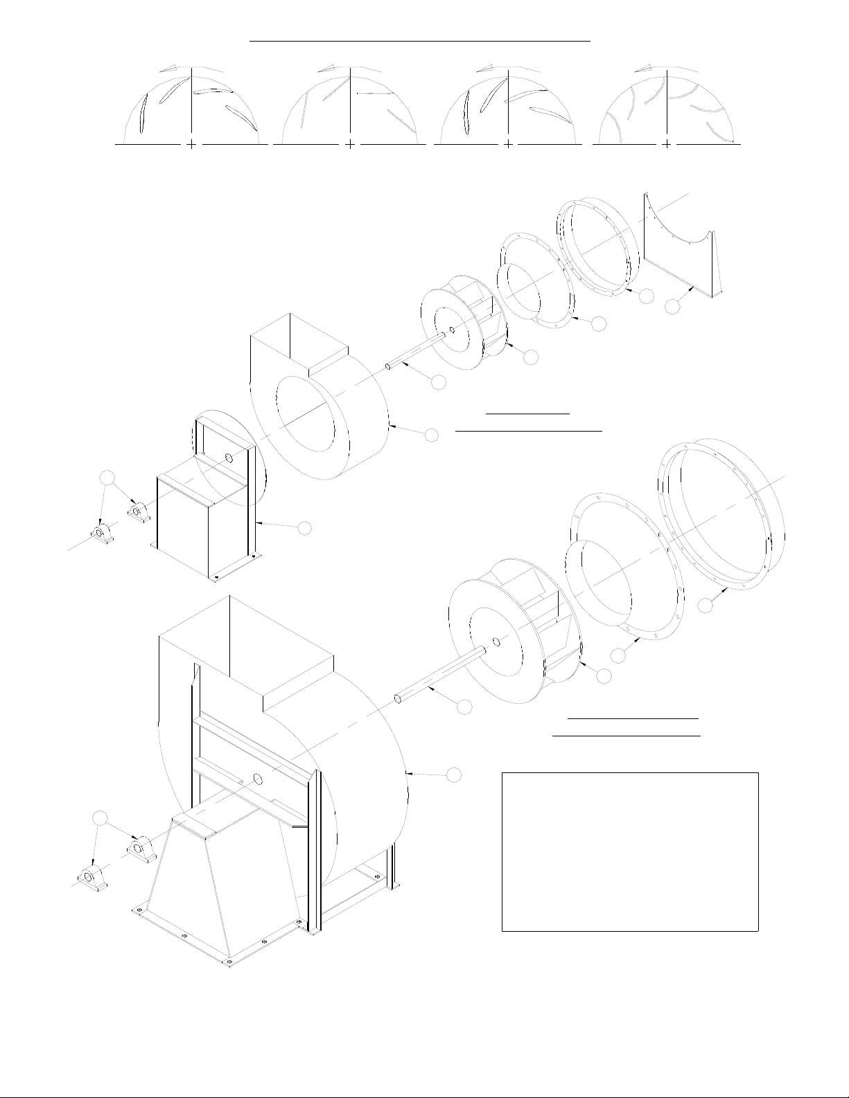
1.INLET HANGER BRACKET
2.INLET COLLAR ASSEMBLY
3.INLET CONE WITH DIVERTER #
4.WHEEL *#
5.SHAFT *
6.HOUSING #
7.HOUSING/BEARING
PEDESTAL ASSEMBLY
8.DRIVE SIDE HANGER ASSEMBLY
9.BEARINGS *
PARTS LIST
When ordering replacement parts
supply nyb shop number from
nameplate and complete description
of parts required.
*Suggested Repair Parts
#Order for parts must
specify rotation.
WHEEL ROTATION AS VIEWED FROM DRIVE SIDE
(COUNTERCLOCKWISE)
ACF PLR AF-FORTY RTS
ARROW INDICATES CORRECT ROTATION
9
4
5
3
2
1
For assistance in selecting replacement parts, contact your local
nyb representative or visit: http://www.nyb.com.
Form 218 JLK
 Loading...