

Page 1
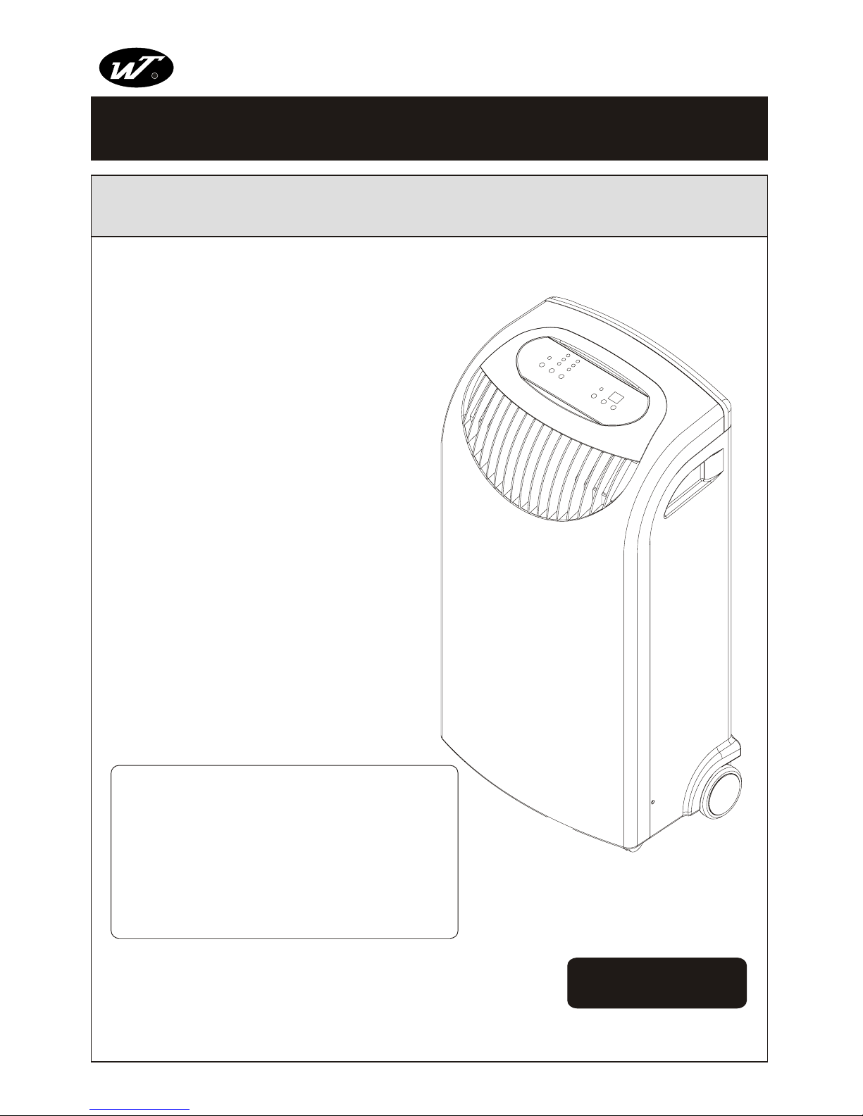
SERVICE MANUAL
220-240V 50Hz
PORTABLE AIR CONDITIONER
NEW WIDETECH
R
WIDETECH
WIDETECH
This manual is for the use of technical personnel entrusted
with maintenance.
Widetech reserves the right to change this dehumidifier's
casing, circuit and parts without notice.
PAC-10000DB
Important points on service, and flow chart for
inspecting and repairing the unit......................... 1
Appearance(out ward)........................................ 2
Troubleshooting.................................................. 3
Functions and control panel................................. 4
Technical specifications................................. 5 - 6
Refrigerator system diagram and schematic wiring
diagram.............................................................. 7
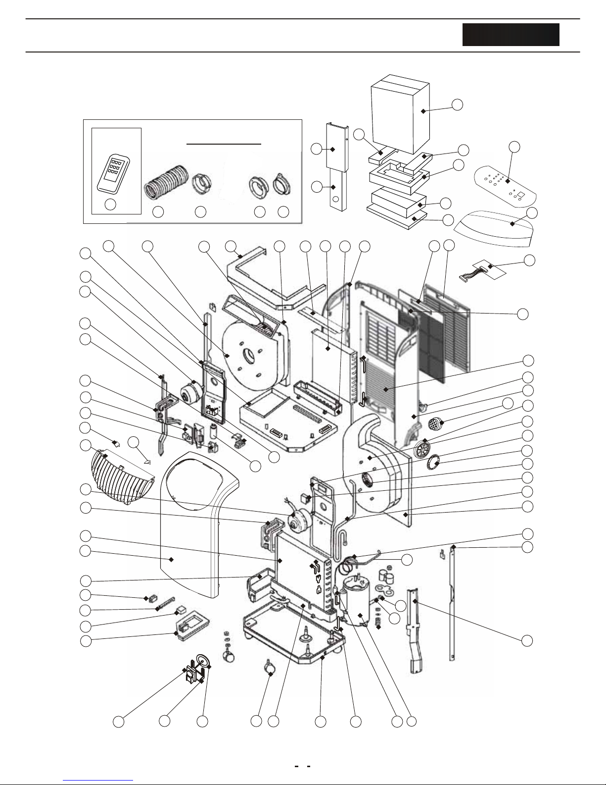
Exploded view.................................................... 8
Parts list....................................................... 9 -11
Page 2
1
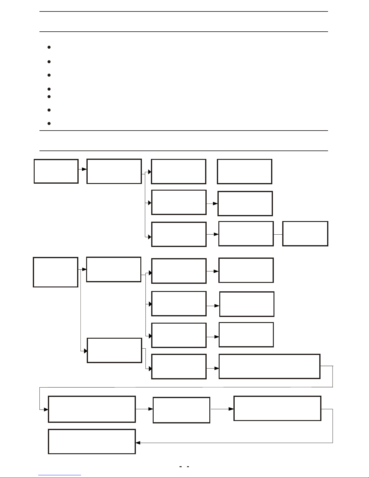
PLUG AND SOCKET
ARE LOOSE
RE-PLUGING THE
POWER SUPPLY CORD
AIR CONDITIONER
WON'T COOL
PROPERLY
AIR CONDITIONER
WON'T START
COMPRESSOR WON'T
START
TIMER FAILURE
CHANGE THE
PROTECTOR
RUNNING TEST
RE-CONNECTING
NO POWER
PROTECTOR FAILURE
USE OXYACETYLENE AND PLUS 5%
SILVER SOLDER TO WELD THE
CRACKED POINTS
WIRING IS LOOSE
CAPACITOR FAILURE
CHANGE THE SWITCH
CHANGE THE
CAPACITOR
TESTING BY
ELECTROSCOPE
POWER TRIPPED
CHECK THE POWER
SWITCH
REFRIGERANT
LEAKAGE
TROUBLE SHOOTING
THE SYSTEM
RUNNING THE VACUUM
EVACUATION FOR MORE
THAN 15 MINUTES
CHANGE COOLANT AND
PROCEED RUNNING TEST
CHANGE THE AIR CONDITIONER WITH 15KG/CM
2
NITROGEN GAS FROM LOW-PRESSURE SIDE AND
DETECT THE LEAKING POINT BY SOAP
Please follow these instructions carefully:
Unplug the unit to avoid any danger from electric shock before disassembling the unit for
repair.
If there is any sound of the refrigerant circulating when in operation, avoid touching the
cooling coils.
If you need to perform any welding or soldering, be sure you are in a well ventilated area.
Only a qualified professional should perform any welding on the unit.
When repairing the unit, the specifications listed in this manual must be strictly adhered
to when replacing any components.
When replacing any electrical components they should be factory approved units.
Be sure that any electrical components are properly wired and in place.
FLOW CHART FOR INSPECTING AND REPAIRING THE UNIT
IMPORTANT POINTS ON SERVICE OPERATING SAFETY
Page 3
APPEARANCE(OUT WARD)
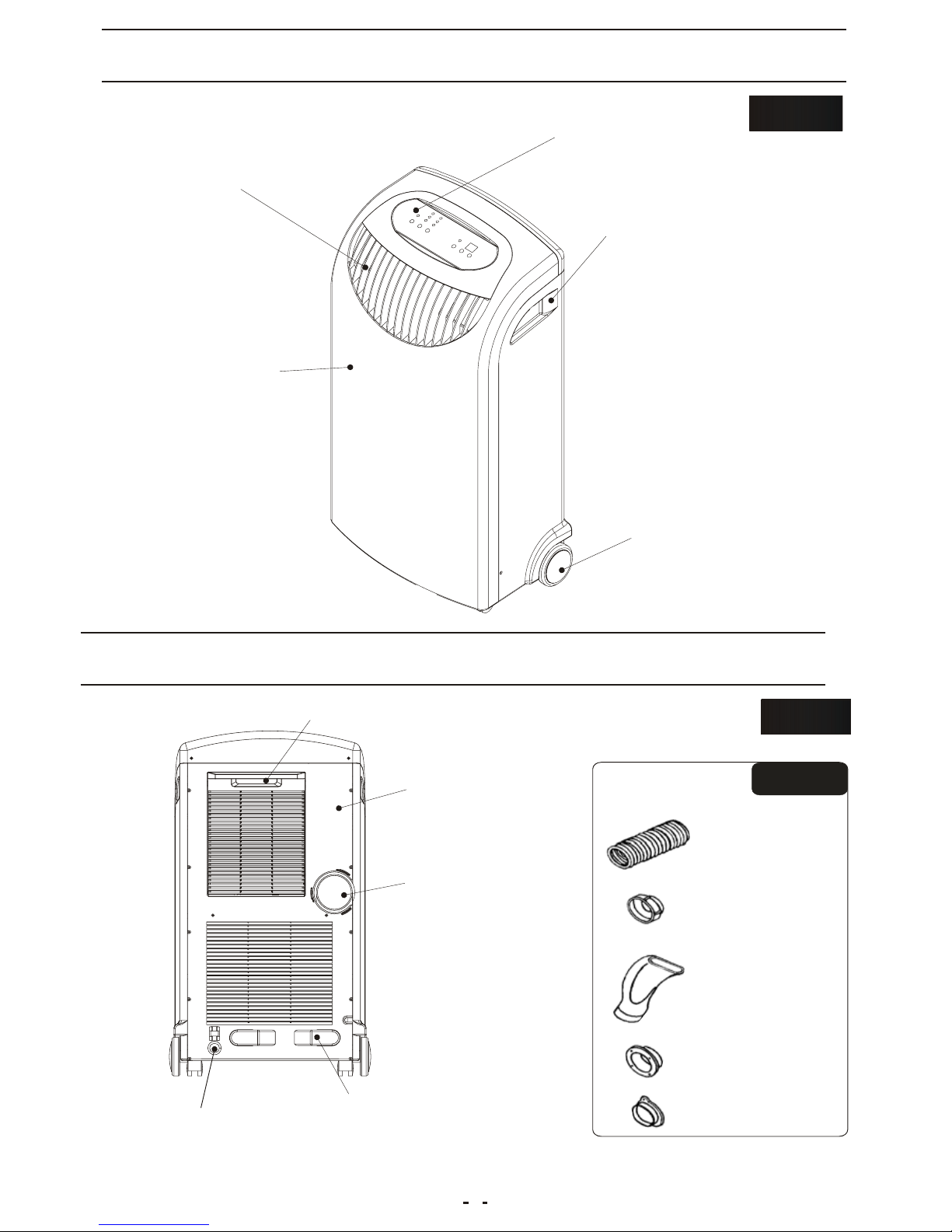
ACCESSORIES
ACCESSORIES
AIR FILTER
FIX TURE
APPEARANCE(OUT WARD)
FRONT SIDE
FRONT SIDE
DISCHARGE GRILLE
(COMPLETE)
POWER SUPPLY CORD
DRAINAGE PIPE
BACK SIDE
BACK SIDE
REAR COVER
HEAT EXHAUST
HOSE CONNECTOR
FIX TURE
CAP
FIX TURE
control panel
Handle hole
Front panel
Caster
Air outlet
2
Page 4
TROUBLESHOOTING
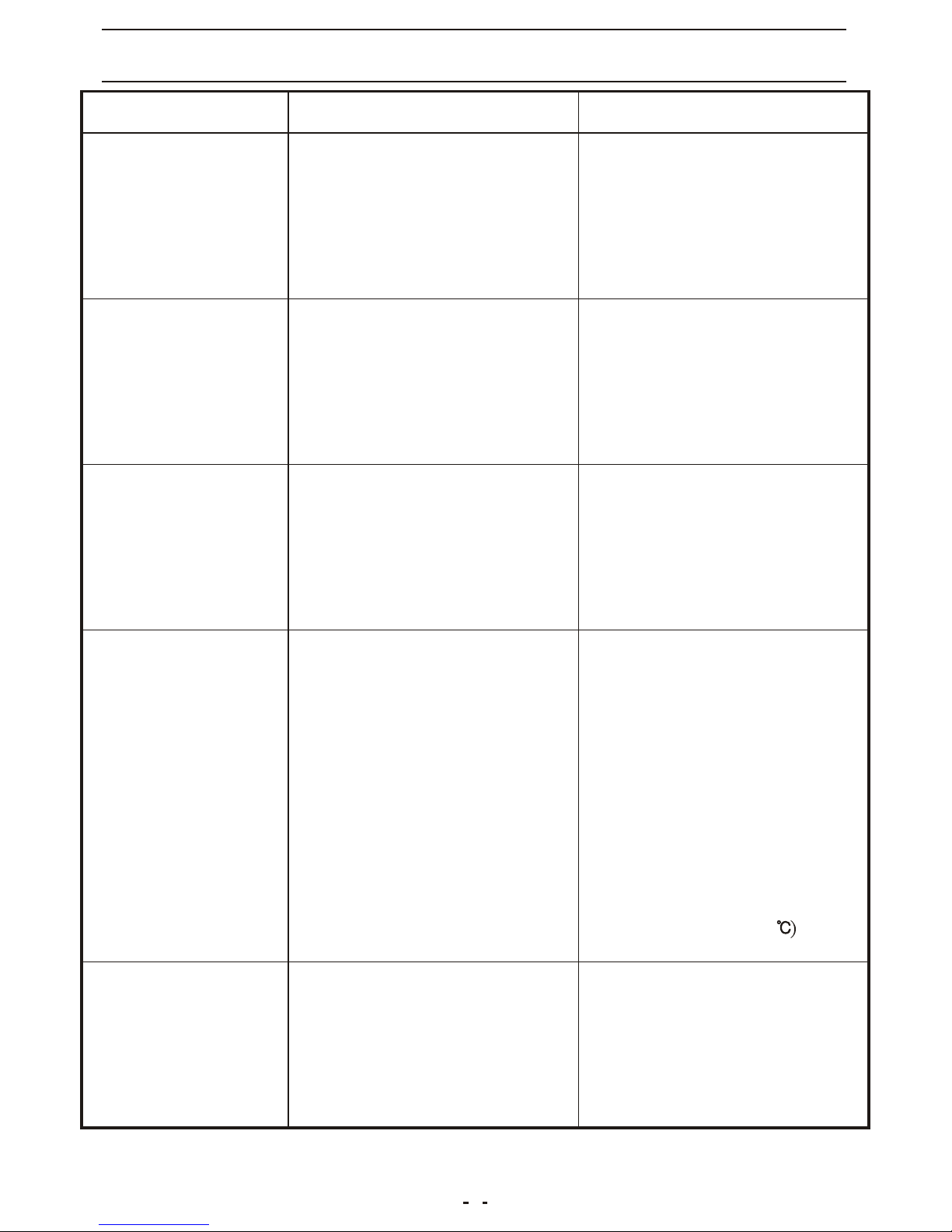
PROBLEM
POSSIBLE CAUSE
REMEDIES
The air conditioner
doesn't work
The air conditioner
works but it does
not cool the room
The appliance is
very noisy and
vibrates violently
The air conditioner
works for short
period only
The air conditioner
switches are off
constantly
-Malfunction
-Decrease the setting
temperature
-Remove any obstacles
-Provide repairment
-There is a window opened
-There is a source of heat
operating in the room
(burner, lamp, etc.), or the
room is crowded
-The air filter is clogged
-The capacity of the air
conditioner is not suitable
for the conditions or size
of the room
-The evaporator is frozen
-The compressor blocking
device has been loosen or
the copper pipe is getting
in touch with the body of
the set
-The set temperature is too
close to the room's
temperature
-There is something blocking
the suction vent on the
back of condenser
-The fan on the condenser is
blocked
-There is a power failure
-The plug is not connected
-The timer is unable to work
-The main switch has not
been pressed
-Close the window
-Remove/switch off the
source of heat
-Decrease the set
temperature
-Clean the filter
-Clean the air filter
-Change the purifier filter,
if necessary
-Do not make the appliance
operating at too low
temperature(below22
-Provide repairment
-Wait for the power return
-Connect the plug
-Provide repairment
-Press the main switch
-Turn off the appliance
remove the plug and
contact the service center
3
Page 5
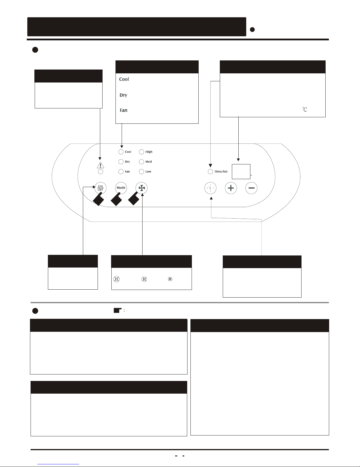
C
Fan Speed Key
: lamp is on when in
cooling mode
Set-up of Function key
Temperature & Timer set-up key
Temperature & Timer set-up key
. Time on or Time off mode:
Timer setting.(1-12 Hours)
. Cooling or Dehumidification mode:
Temperature setting.(16~32 )
Power Key
On / Off
On / Off Timer Key
On / Off Timer Key
In running mode :
Auto switch off
In standby mode:
Auto switch on
Full-Tank Indicator
See the troubleshooting
when the lamp is on.
Operation of PAC-10000DB(10000 B.T.U.)
Operation
Operation
1. Make sure power cord is properly connected.
(Standby)
2. Press " On / Off " key.
3. Setup function key to " Fan "
4. Select proper fan speed by actual situation.
A. Auto switch off
1) To be operated in cooling or fan mode.
2) Press " Auto on / off " key for machine's
stopping operation after 1,2,3,......,12 hours .
B. Auto switch on
1) Be sure that machine is in standby mode.
( power cord is securely plugged )
2) Press " Auto on / off " key for machine's
starting operation after 1,2,3,.....,12 hours.
Air conditioning
NAME OF THE PARTS
NAME OF THE PARTS
Symbols Operation procedure
Easy operation
1. Make sure power cord is properly connected.
(Standby)
2. Press " On / Off " key .
3. Setup function key to " air conditioning " if necessary.
4. Select proper fan speed by actual situation if necessary.
Fan mode
Operation procedure for auto switch on/off
:HIGH :MED :LOW
: lamp is on when in
fan mode
: lamp is on when in
dehumidification mode
3
4
2
4
Page 6
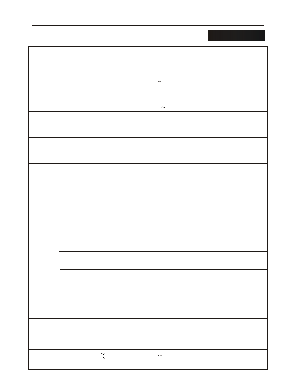
TECHNICAL SPECIFICATIONS
AIR CONDITIONER
ITEM UNIT
OUTER DIMENSION
RATED VOLTAGE
RUNNING VOLTAGE
COOLING CAPACITY
DEHUMIDIFYING
CAPACITY
RUNNING CURRENT
POWER
CONSUMPTION
INDOOR AIR VOLUME
COMPRESSOR
MODEL
OUTPUT
POWER
OPERATING
CYCLE
PROTECTOR
MODEL
INPUT
POWER
TURBINE
FAN MOTOR
CAPILLARY
CONDENSER
REFRIGERANT
WEIGHT
REFERENTIAL USING
AREA
2
mm
m
V/Hz
V
B.T.U.
L/H
A
W
m/hr
W
uF/V
A
mm
uF/V
R22/g
3
APPLICABLE AMBIENT
TEMPERATURE
524W*897H*347D
220~240/50
198 264
1035
420
18 35
KETC154ELBABA
950~975
25/450
16.5
WA90S2
12
1.5/450
2.6(O.D.)*1.4(I.D.)*950(L)
2R13S16FPI
PAC-10000DB
10000
Kg
13 19
1.8
440
MRA90255-9079
32
OPERATING
CYCLE
MODEL
OUTPUT
POWER
INDOOR
MOTOR
W
uF/V
WTC-13G
30
1/400
OPERATING
CYCLE
MODEL
OUTPUT
POWER
OUTDOOR
MOTOR
W
WTC-43G
43
EVAPORATOR
2R11S17FPI
W
LOCKED
ROTOR AMPS
4.71
5
Page 7
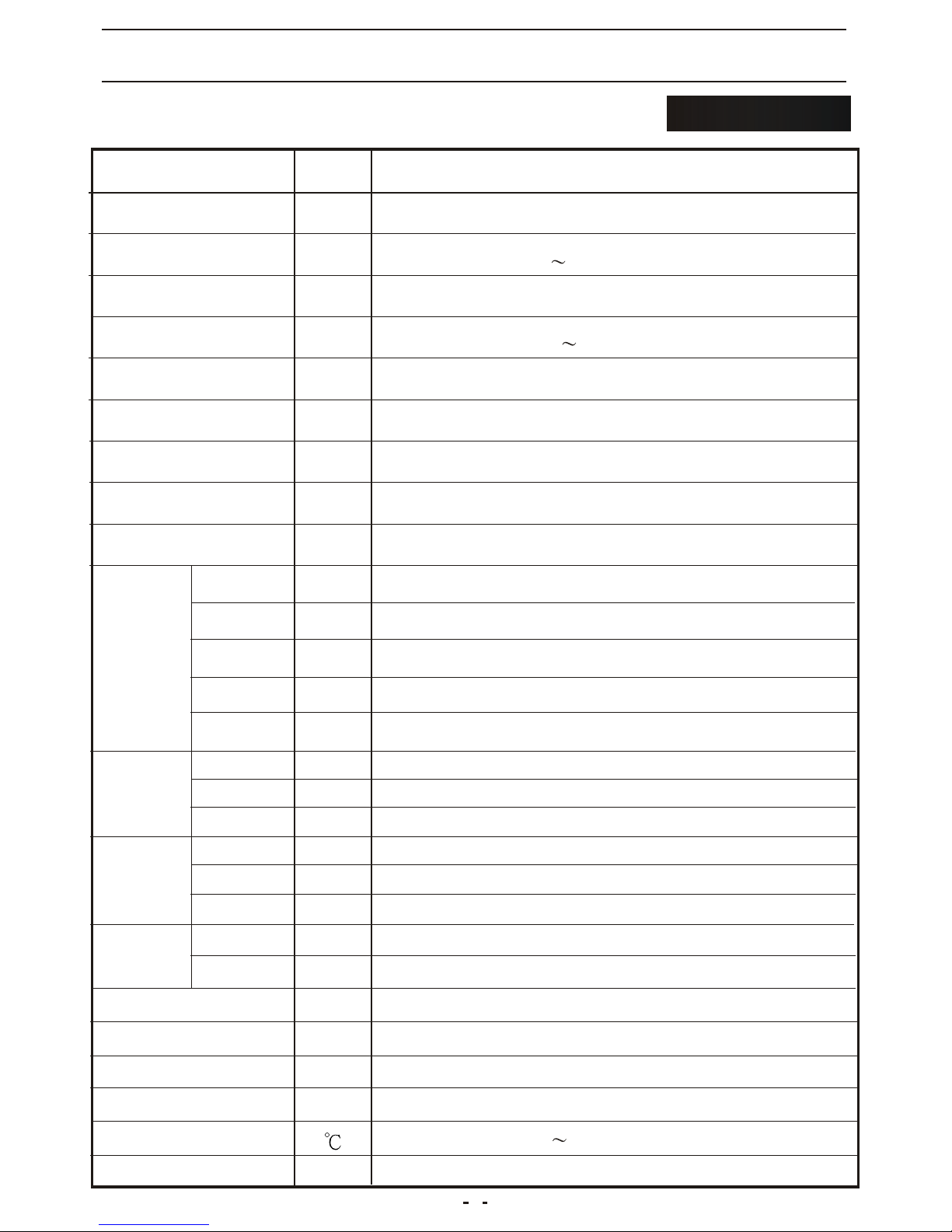
TECHNICAL SPECIFICATIONS
AIR CONDITIONER
ITEM UNIT
OUTER DIMENSION
RATED VOLTAGE
RUNNING VOLTAGE
COOLING CAPACITY
DEHUMIDIFYING
CAPACITY
RUNNING CURRENT
POWER
CONSUMPTION
INDOOR AIR VOLUME
COMPRESSOR
MODEL
OUTPUT
POWER
OPERATING
CYCLE
PROTECTOR
MODEL
INPUT
POWER
TURBINE
FAN MOTOR
CAPILLARY
CONDENSER
REFRIGERANT
WEIGHT
REFERENTIAL USING
AREA
2
mm
m
V/Hz
V
B.T.U.
L/H
A
W
m/hr
W
uF/V
A
mm
uF/V
3
APPLICABLE AMBIENT
TEMPERATURE
460W*780H*320D
220~240/50
207 253
900
320
18 35
WA90S2
12
1.5/450
2R13S16FPI
PAC-10000DB
9000
Kg
13 19
1.6
440
AIR CONDITIONER
32
OPERATING
CYCLE
MODEL
OUTPUT
POWER
INDOOR
MOTOR
W
uF/V
WTC-13G
30
1/400
OPERATING
CYCLE
MODEL
OUTPUT
POWER
OUTDOOR
MOTOR
W
WTC-43G
43
EVAPORATOR
2R11S17FPI
W
NK134PL12C
738/762
25/370
19
2.6(O.D.)*1.4(I.D.)*600(L)
MRA12012-12026
R407c/g
LOCKED
ROTOR AMPS
5.0
6
Page 8
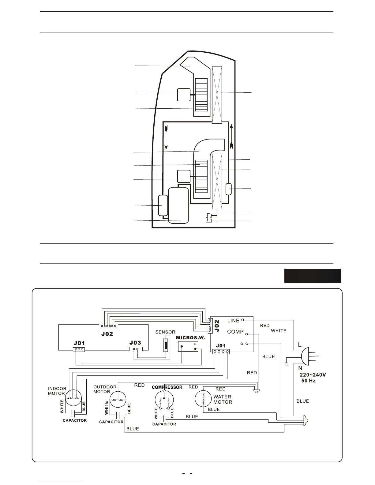
EVAPORATOR
INDOOR
RADIATOR DRUM
INDOOR MOTOR
INDOOR
RADIATOR FAN
OUTDOOR
RADIATOR DRUM
OUTDOOR
MOTOR
OUTDOOR
RADIATOR FAN
STRIKE WATER MOTOR
WATER PADDIE
AIR FILTER
CONDENSOR
CAPILLARY
LIQUID
ACCUMULATOR
COMPRESSOR
SCHEMATIC WIRING DIAGRAM
REFRIGERATOR SYSTEM DIAGRAM
PAC-10000DB
7
T01(NATURE)
Page 9
63
49
42
37
36
35
30
59
28
27
32
34
41
46
38
29
23
20
26
22
21
19
25
24
15
17
31
14
1
12
13
11
4
6
5
7
3
53
52
55
33
56
61
60
47
42
16
ACCESSOR
10
40
51
41
69
EXPLODED VIEW
PAC-10000DB
62
57
58
64
68
67
44
45
65
66
43
2
70
72
74
71
75
73
39
48
54
18
9
8
50
OPTION
8
Page 10
PARTS LIST
MATERIAL CODE
PARTS NAME
QUANTITY
NO
1
2
3
4
5
6
7
8
9
10
11
12
13
14
15
16
17
18
19
20
21
22
23
24
25
26
27
28
29
30
31
32
33
34
35
BASE PAN ASS'Y
TURING WHEEL
DRAIN BUCKET
DRAIN BUCKET COVER
RENK
FLOAT
MICRO SWITCH
DRAINAGE PIPE
SOFT CAP
DRAINAGE PAN
FAN MOTOR
BLADE
STRIKE
COMPRESSOR ASS'Y
CONDENSER
STRAINER COMPLETE
SERVICE TUBE
DISCHARGE PIPE
SUCTION PIPE
STRIKE
STRIKE
FAN MOTOR
FAN CASING
FAN CASING
BLOWER WHEEL
CAPACITOR
PLATE
DRAINAGE PAN
TERMINAL BLOCK
EVAPORATOR
CAPILLARY TUBE
STRIKE
STRIKE
FAN MOTOR
FAN CASING
A4802-010
A7402-010
A5401-010-A-11
A5408-010-H-11
A5410-010-A-11
A5404-010
A2506-020
V02P11-100
A7307-010
A5001-070-A-11
A3000-430
A5311-030-A-22
A5802-410
A3202-080
A3404-140
A3408-010
A6202-010
A6208-390
A6227-510
A5802-070
A5802-080
A3000-360
A5301-070-A-22
A5301-090-A-22
A5304-050-A-22
A2509-320
A5700-010
A5001-110-P-22
A2525-010
A3400-130
A6204-220
A5802-030
A5802-040
A3000-330
A5301-110-A-22
1
2
1
1
1
1
1
1
1
1
1
1
1
1
1
1
1
1
1
1
1
1
1
1
1
1
1
1
1
1
1
1
1
1
1
PRICE
9
Page 11
NO
36
37
38
39
40
41
42
43
44
45
46
47
48
49
50
51
52
53
54
55
56
57
58
59
60
61
62
63
64
65
66
67
68
69
70
PARTS LIST
1
1
1
1
1
2
2
1
1
1
1
1
1
1
1
1
1
1
1
1
1
1
1
1
1
2
2
1
1
1
1
1
1
1
1
A5301-130-A-22
A5304-070-A-22
A2509-060
A2525-020
A5900-010
A5802-020
A5802-010
A4254-150-A-BS
A6931-190-Z
A2520-120
A2516-160
A3700-200
A6102-050-A-BS
A2509-080
A5700-020
A4211-130-A-BS
A4211-150-A-BS
A4238-090-A-BS
A4201-130-A-BS
A6102-070-A-BS
A5805-030-A-BS
A4219-130-A-BS
A7301-070-A-BS
A7315-010-A-BS
A6101-090-A-BS
A7402-030
A4206-110-A-BS
A6200-010
A5812-010-H-BS
A5700-100
A5700-110
A5815-050-A-BS
A6101-010-H-BS
A2529-080
A7010-090
FAN CASING
BLOWER WHEEL
CAPACITOR
TERMINAL BLOCK
TOP BOARD
STRIKE
STRIKE
CONTROL PLATE
PC BOARD
CONTROL BOARD
POWER SUPPLY CORD COMPLETE
SCREW TOP COVER
CONTROL PANEL
CAPACITOR
PLATE
SIDE PLATE
SIDE PLATE
DISCHARGE GRILLE
FRONT PANEL
SCREW TOP COVER
FIX TURE
REAR COVER
AIR FILTER
FILTER FRAME
CAP
TURING WHEEL
TOP COVER PLATE
HEAT EXHAUST HOSE CONNECTOR
FIX TURE
PLATE
PLATE
FIX TURE
CAP
REMOTE CONTROL
CARTON
MATERIAL CODE
PARTS NAME
QUANTITY
PRICE
10
Page 12
PARTS LIST
1
1
1
1
1
A7012-580
A7107-250
A7107-260
A7107-270
A7105-120
CARTON
SHOCK ABSORBER
SHOCK ABSORBER
SCREW TOP COVER
CARTON BASE
NO
71
72
73
74
75
MATERIAL CODE
PARTS NAME
QUANTITY
PRICE
11
 Loading...