

Page 1
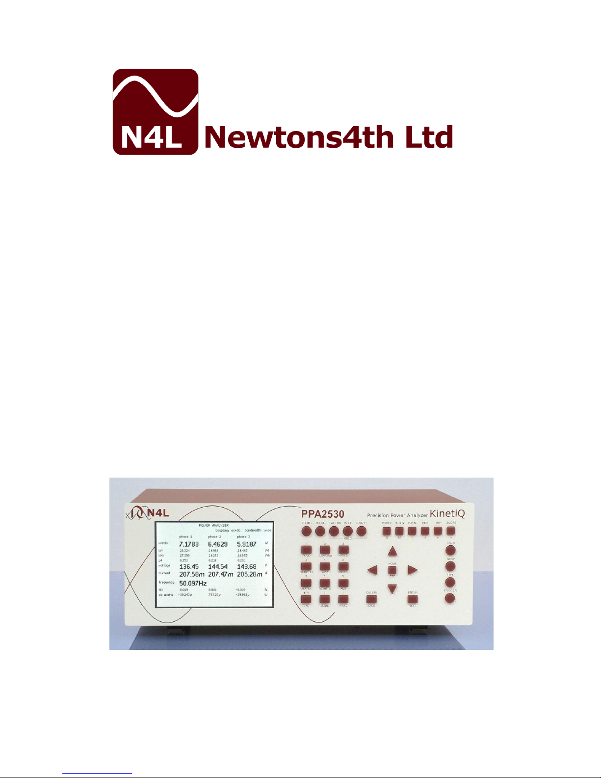
PPA2500
PPA2600
KinetiQ
Communications
manual
Firmware v1.100
10th April 2017
Page 2

PPA25/26xx communications manual
i
IMPORTANT SAFETY INSTRUCTIONS
This equipment is designed to comply with BSEN 61010-1
(2001) (Safety requirements for electrical equipment for
measurement, control, and laboratory use) – observe the
following precautions:
Ensure that the supply voltage agrees with the rating of
the instrument printed on the back panel before
connecting the mains cord to the supply.
This appliance must be earthed. Ensure that the
instrument is powered from a properly grounded supply.
The inputs are rated at 1kV rms or dc cat II; 600V rms
or dc cat III. Do not exceed the rated input.
Keep the ventilation holes on the underneath and rear
free from obstruction.
Do not operate or store under conditions where
condensation may occur or where conducting debris
may enter the case.
There are no user serviceable parts inside the
instrument – do not attempt to open the instrument,
refer service to the manufacturer or his appointed
agent.
Note: Newtons4th Ltd. shall not be liable for any
consequential damages, losses, costs or expenses
arising from the use or misuse of this product
however caused.
Page 3

PPA25/26xx communications manual
ii
ABOUT THIS MANUAL
This manual gives details of the communication commands
recognized by the PSM25/26xx series of instruments over
RS232, USB, LAN or GPIB. For more general operating
instructions for the instrument refer to the specific user
manual.
Each command is listed alphabetically with details of any
arguments and reply. A one line summary of each
command is given in the appendix. Although most of the
commands apply to all instruments in the range there are
some commands that are specific to one instrument or
another.
The information in this manual is believed to be accurate
and complete but Newtons4th Ltd cannot accept any
liability whatsoever for any consequential damage or
losses arising from any errors, inaccuracies, or omissions.
Revision 1.100
This manual is copyright © 2006-2017 Newtons4th Ltd.
and all rights are reserved. No part may be copied or
reproduced in any form without prior written consent.
10th April 2017
Page 4

PPA25/26xx communications manual
iii
CONTENTS
1 Using remote control .......................................... 1-1
1.1 Standard event status register .................................. 1-3
1.2 Serial Poll status byte .............................................. 1-4
1.3 RS232 connections .................................................. 1-5
1.4 Data format............................................................ 1-6
2 Communication commands .................................. 2-1
*CLS ................................................................................ 2-1
*ESE ................................................................................ 2-2
*ESR? ............................................................................... 2-3
*IDN? ............................................................................... 2-4
*OPC? .............................................................................. 2-5
*RST ................................................................................ 2-6
*SRE ................................................................................ 2-7
*SRE? ............................................................................... 2-8
*STB? ............................................................................... 2-9
*TRG .............................................................................. 2-10
*TST? ............................................................................. 2-11
*WAI .............................................................................. 2-12
ABORT ............................................................................ 2-13
ALARM ............................................................................ 2-14
ALARM? .......................................................................... 2-15
ALARM1 .......................................................................... 2-16
ALARM2 .......................................................................... 2-17
ALARME .......................................................................... 2-18
ALARME? ......................................................................... 2-19
APPLIC ............................................................................ 2-20
BANDWI.......................................................................... 2-21
BANDWI? ........................................................................ 2-22
BEEP .............................................................................. 2-23
BLANKI ........................................................................... 2-24
CALVER........................................................................... 2-25
CALVER? ......................................................................... 2-26
CONFIG .......................................................................... 2-27
CONFIG? ......................................................................... 2-28
COUPLI ........................................................................... 2-29
COUPLI? ......................................................................... 2-30
DATALO .......................................................................... 2-31
DATALO? ......................................................................... 2-32
DAV? .............................................................................. 2-33
Page 5

PPA25/26xx communications manual
iv
DAVER ............................................................................ 2-34
DAVER? .......................................................................... 2-35
DISPLAY ......................................................................... 2-36
DISPLAY? ........................................................................ 2-37
EFFICI ............................................................................ 2-38
EFFICI? ........................................................................... 2-39
FAST .............................................................................. 2-40
FQLOCK .......................................................................... 2-41
FQREF ............................................................................ 2-42
FREQUE .......................................................................... 2-43
HARMON ......................................................................... 2-44
HARMON? ....................................................................... 2-45
HOLD.............................................................................. 2-46
INPUT ............................................................................. 2-47
INTEGR ........................................................................... 2-48
INTEGR? ......................................................................... 2-49
KEYBOA .......................................................................... 2-50
LCR ................................................................................ 2-51
LCR?............................................................................... 2-52
LOWFRE .......................................................................... 2-53
MODE ............................................................................. 2-54
MSLAVE .......................................................................... 2-55
MULTIL ........................................................................... 2-56
MULTIL? .......................................................................... 2-57
NOOVER ......................................................................... 2-58
PFCONV .......................................................................... 2-59
PHASEM .......................................................................... 2-60
PHASEM? ........................................................................ 2-61
PHCONV .......................................................................... 2-62
POWER ........................................................................... 2-63
POWER? .......................................................................... 2-64
PROGRA .......................................................................... 2-66
PROGRA? ........................................................................ 2-67
RANGE ............................................................................ 2-68
RESOLU .......................................................................... 2-69
RESULT ........................................................................... 2-70
RESULT? ......................................................................... 2-71
REZERO .......................................................................... 2-72
SCALE ............................................................................ 2-73
SCOPE?........................................................................... 2-74
SCREEN? ......................................................................... 2-75
SETUP ............................................................................ 2-76
SETUP? ........................................................................... 2-77
SHUNT ............................................................................ 2-78
Page 6

PPA25/26xx communications manual
v
SMOOTH ......................................................................... 2-79
SPEED ............................................................................ 2-80
START ............................................................................ 2-81
STATUS? ......................................................................... 2-82
STOP .............................................................................. 2-83
SUSPEN .......................................................................... 2-84
TEMPER .......................................................................... 2-85
TEMPER? ......................................................................... 2-86
TORQSP .......................................................................... 2-87
TORQSP? ........................................................................ 2-88
USER? ............................................................................ 2-89
VARCON.......................................................................... 2-90
VERSIO? ......................................................................... 2-91
VRMS ............................................................................. 2-92
VRMS? ............................................................................ 2-93
WIRING .......................................................................... 2-94
ZERO .............................................................................. 2-95
ZOOM ............................................................................. 2-96
ZOOM? ........................................................................... 2-97
Appendix A – command summary
Appendix B – configurable parameters
Appendix C – MULTILOG parameters
Page 7

PPA25/26xx communications manual
1-1
1 Using remote control
The instrument is fitted with an RS232 serial
communications port and USB interface as standard, and
may have an IEEE488 (GPIB) interface or LAN interface
fitted as an option. All the interfaces use the same ASCII
protocol with the exception of the end of line terminators:
Rx expects
Tx sends
RS232
USB, LAN
carriage return
(line feed ignored)
carriage return
and line feed
IEEE488
carriage return or
line feed or EOI
carriage return
with EOI
All the functions of the instrument can be programmed via
any interface, and results read back. When the IEEE488
interface is set to ‘remote’ the other ports are ignored.
The commands are not case sensitive and white space
characters are ignored (e.g. tabs and spaces). Replies
from the instrument are always upper case, delimited by
commas, without spaces.
Only the first six characters of any command are important
– any further characters will be ignored. For example, the
command to set the generator frequency is FREQUE but
the full word FREQUENCY may be sent as the redundant
NCY at the end will be ignored.
Fields within a command are delimited by comma, multiple
commands can be sent on one line delimited with a semicolon. Eg.
FQREF,CURRENT;POWER?
Mandatory commands specified in the IEEE488.2 protocol
have been implemented, (e.g. *IDN?, *RST) and all
commands that expect a reply are terminated with a
question mark (query).
Page 8

PPA25/26xx communications manual
1-2
The instrument maintains an error status byte consistent
with the requirements of the IEEE488.2 protocol (called
the standard event status register) that can be read by the
mandatory command *ESR? (see section 5.1).
The instrument also maintains a status byte consistent
with the requirements of the IEEE488.2 protocol, that can
be read either with the IEEE488 serial poll function or by
the mandatory command *STB? over RS232 or IEEE or
LAN (see section 5.2).
The IEEE address defaults to 23 and can be changed via
the COMMS menu.
The keyboard is disabled when the instrument is set to
“remote” using the IEEE. Press HOME to return to “local”
operation.
RS232 data format is: start bit, 8 data bits (no parity), 1
stop bit. Flow control is RTS/CTS (see section 5.2), baud
rate is selectable via the MONITOR menu.
A summary of the available commands is given in the
Appendix. Details of each command are given in the
communication command section of the manual.
Commands are executed in sequence except for two
special characters that are immediately obeyed:
Control T (20) – reset interface (device clear)
Control U (21) – warm restart
Page 9

PPA25/26xx communications manual
1-3
1.1 Standard event status register
PON
CME
EXE
DDE
QYE
OPC
bit 0 OPC (operation complete)
cleared by most commands
set when data available or sweep complete
bit 2 QYE (unterminated query error)
set if no message ready when data read
bit 3 DDE (device dependent error)
set when the instrument has an error
bit 4 EXE (execution error)
set when the command cannot be executed
bit 5 CME (command interpretation error)
set when a command has not been recognised
bit 7 PON (power on event)
set when power first applied or unit has reset
The bits in the standard event status register except for
OPC are set by the relevant event and cleared by specific
command (*ESR?, *CLS, *RST). OPC is also cleared by
most commands that change any part of the configuration
of the instrument (such as MODE or START).
Page 10

PPA25/26xx communications manual
1-4
1.2 Serial Poll status byte
ESB
MAV
ALA
RDV
bit 0 RDV (result data available)
set when results are available to be read as
enabled by DAVER
bit 3 ALA (alarm active)
set when an alarm is active and enabled by
ALARMER
bit 4 MAV (message available)
set when a message reply is waiting to be read
bit 5 ESB (standard event summary bit)
set if any bit in the standard event status
register is set as well as the corresponding bit
in the standard event status enable register
(set by *ESE).
Page 11

PPA25/26xx communications manual
1-5
1.3 RS232 connections
The RS232 port on the instrument uses the same pinout as
a standard 9 pin serial port on a PC or laptop (9-pin male
‘D’ type).
Pin
Function
Direction
1
DCD
in (+ weak pull up)
2
RX data
in 3 TX data
out
4
DTR
out
5
GND
6 DSR
not used
7
RTS
out
8
CTS
in 9 RI
not used
The instrument will only transmit when CTS (pin 8) is
asserted, and can only receive if DCD (pin 1) is asserted.
The instrument constantly asserts (+12V) DTR (pin 4) so
this pin can be connected to any unwanted modem control
inputs to force operation without handshaking. The
instrument has a weak pull up on pin 1 as many null
modem cables leave it open circuit. In electrically noisy
environments, this pin should be driven or connected to
pin 4.
To connect the instrument to a PC, use a 9 pin female to 9
pin female null modem cable:
1 & 6
-
4 2 -
3
3
-
2
4
-
1 & 6
5
-
5 7 -
8
8 - 7
Page 12

PPA25/26xx communications manual
1-6
1.4 Data format
Non integer results are sent as ASCII characters in a
scientific format consisting of 5 or 6 digit mantissa plus
exponent:
+1.2345+E00
+1.23456+E00
For higher speed transfer a proprietary binary format can
be selected which compresses the data into 4 bytes, each
of which is sent with the msb set to distinguish them from
ASCII control characters. The data is sent as a 7 bit signed
exponent, a mantissa sign, and a 20 bit mantissa:
byte
data
1
7 bit signed exponent +63 to -64
2
bit 6 = mantissa sign
bit 5:0 = mantissa bit 19:14
3
mantissa bit 13:7
4
mantissa bit 6:0
The value is coded as a binary fraction between 0.5 and
0.9999…, a multiplier of 2^n and a sign ie:
Value = (mantissa / 2^20) x 2^exponent x -1^sign
value
equivalent
hex data transmitted
3.0
0.75 x 2^2
0x82,0xB0,0x80,0x80
0.1
0.8 x 2^-3
0xFD,0xB3,0x99,0xCD
-320
-0.625 x 2^9
0x89,0xE8,0x80,0x80
Any valid number would have the msb of the mantissa set;
any number without the msb of the mantissa set is zero.
Page 13

PPA25/26xx communications manual
2-1
2 Communication commands
*CLS
*CLS
Function:
Clear status
Description:
Clears the standard event status register.
Format:
*CLS
Arguments:
none
Reply:
none
Example:
*CLS
*ESR?
0
Notes:
Page 14

PPA25/26xx communications manual
2-2
*ESE
*ESE
Function:
Set standard event status enable register.
Description:
Enable which bits of the standard event
status register set the ESB bit in the serial
poll status byte..
Format:
*ESE, value
Arguments:
decimal equivalent of bits in standard
event status enable register
Reply:
can be read by *ESE?
Example:
*ESE, 60
Notes:
The following bits in the standard event
status enable register have been
implemented:
bit 0 OPC (operation complete)
bit 2 QYE (unterminated query error)
bit 3 DDE (device dependent error)
bit 4 EXE (execution error)
bit 5 CME (command interpretation error)
bit 7 PON (power on event)
For example, *ESE, 60 enables all the
error bits so that the ESB bit in the serial
poll status byte is set in the event of any
error.
Page 15

PPA25/26xx communications manual
2-3
*ESR?
*ESR?
Function:
Standard event status register query
Description:
Returns the contents of the standard
event status register and clears it.
Format:
*ESR?
Arguments:
none
Reply:
decimal equivalent of bits in standard
event status register
Example:
*ESR?
33
Notes:
The following bits in the standard event
status register have been implemented:
bit 0 OPC (operation complete)
bit 2 QYE (unterminated query error)
bit 3 DDE (device dependent error)
bit 4 EXE (execution error)
bit 5 CME (command interpretation error)
bit 7 PON (power on event)
For example, if a command is sent
incorrectly and is not recognised, the CME
bit will be set and the value of 33 will be
returned.
Page 16

PPA25/26xx communications manual
2-4
*IDN?
*IDN?
Function:
Identify query
Description:
Returns a standard format identification
string.
Format:
*IDN?
Arguments:
none
Reply:
An ASCII string in the IEEE488.2 format:
manufacturer,model,serial no,version
Example:
*IDN?
NEWTONS4TH,PPA2530 KinetiQ,
01234,1.00
Notes:
Page 17

PPA25/26xx communications manual
2-5
*OPC?
*OPC?
Function:
Test for operation complete
Description:
Returns 1 if previous operation is
completed, 0 if not.
Format:
*OPC?
Arguments:
none
Reply:
0 or 1
Example:
START
*OPC?
0
*OPC?
0
*OPC?
1
Notes:
*OPC? can be used to indicate when data
is available or when a frequency sweep
has completed.
Page 18

PPA25/26xx communications manual
2-6
*RST
*RST
Function:
Reset
Description:
Resets the instrument to the default state
and clears the standard event status
register.
Format:
*RST
Arguments:
none
Reply:
none
Example:
*RST
Notes:
The *RST command loads the default
configuration. This is the same as loading
the default configuration via the
PROGRAM menu.
Any preceding setup commands will be
overwritten.
Page 19

PPA25/26xx communications manual
2-7
*SRE
*SRE
Function:
Set service request enable register.
Description:
Enable which bits of the status byte
register initiate a service request.
Format:
*SRE, value
Arguments:
decimal equivalent of bits in status byte
register
Reply:
can be read by *SRE?
Example:
*SRE, 1
generate a service request when data
available.
Notes:
Page 20

PPA25/26xx communications manual
2-8
*SRE?
*SRE?
Function:
Read service request enable register.
Description:
Read back the present setting of the
service request enable register.
Format:
*SRE?
Arguments:
Reply:
decimal equivalent of bits in status byte
register that would generate a service
request.
Example:
*SRE?
1
Notes:
Page 21

PPA25/26xx communications manual
2-9
*STB?
*STB?
Function:
Read serial poll status byte
Description:
Returns the decimal value of the serial
poll status byte.
Format:
*STB?
Arguments:
none
Reply:
decimal value of the serial poll status byte
Example:
*STB?
1
Notes:
The following bits in the serial poll status
register have been implemented:
bit 0 RDV (results data available)
bit 3 ALA (alarm active)
bit 4 MAV (message available)
bit 5 ESB (standard event summary bit)
Page 22

PPA25/26xx communications manual
2-10
*TRG
*TRG
Function:
Trigger
Description:
Initiates a new measurement, resets the
range and smoothing.
Format:
*TRG
Arguments:
none
Reply:
none
Example:
MODE,VRMS
*TRG
VRMS,SURG?
Notes:
Page 23

PPA25/26xx communications manual
2-11
*TST?
*TST?
Function:
Self test query
Description:
Returns the results of self test
Format:
*TST?
Arguments:
none
Reply:
single integer
bit 0 – set if uncalibrated
bit 1 – set if error with analogue zero
> 15 – major system error
Example:
*TST?
0
Notes:
Page 24

PPA25/26xx communications manual
2-12
*WAI
*WAI
Function:
Wait for operation complete
Description:
Suspends communication until the
previous operation has completed
Format:
*WAI
Arguments:
none
Reply:
none
Example:
*TRG
*WAI
POWER,PHASE1?
Notes:
Page 25

PPA25/26xx communications manual
2-13
ABORT
ABORT
Function:
Abort datalog
Description:
Abort datalog data acquisition.
Format:
ABORT
Arguments:
none
Reply:
none
Example:
DATALOG,RAM,0.02
START
wait for data values
ABORT
Notes:
Page 26

PPA25/26xx communications manual
2-14
ALARM
ALARM
Function:
Set common controls for alarm1 and
alarm2.
Description:
Set the alarm latch and sounder control.
Format:
ALARM,latch,sounder
Arguments:
latch:
ON
OFF
sounder:
ENABLED
DISABLED
Reply:
none
Example:
ALARM,ON,DISABLED
Notes:
Page 27

PPA25/26xx communications manual
2-15
ALARM?
ALARM?
Function:
Read alarm status.
Description:
Reads the status of the measurements
and 2 alarms.
Format:
ALARM?
Arguments:
none
Reply:
single integer
bit 0 data available
bit 1 data error
bit 2 alarm 1
bit 3 alarm 2
Example:
ALARM?
1
Notes:
An alarm is present if bit 0 is high (data is
available) and either alarm 1 or alarm 2
bits are high.
Page 28

PPA25/26xx communications manual
2-16
ALARM1
ALARM1
Function:
Set parameters for alarm1.
Description:
Set alarm1 type and thresholds.
Format:
ALARM1,type,data,high,low
Arguments:
type:
DISABLED
HIGH
LOW
INSIDE
OUTSIDE
LINEAR
data
1-4
high:
high threshold
low:
low threshold
Reply:
none
Example:
ALARM1,HIGH,1,2,0
Notes:
Both thresholds must be sent even if only
one is used.
Page 29

PPA25/26xx communications manual
2-17
ALARM2
ALARM2
Function:
Set parameters for alarm2.
Description:
Set alarm2 type and thresholds.
Format:
ALARM2,type,data,high,low
Arguments:
type:
DISABLED
HIGH
LOW
INSIDE
OUTSIDE
data
1-4 for zoom data
high:
high threshold
low:
low threshold
Reply:
None
Example:
ALARM2,LOW,3,0,0.5
Notes:
Both thresholds must be sent even if only
one is used.
There is no LINEAR option for alarm 2.
Page 30

PPA25/26xx communications manual
2-18
ALARME
ALARME
Function:
Set alarm status enable register
Description:
Sets bits in the alarm status enable
register to control which alarm bit if any
set the alarm active bits in the status
byte.
Format:
ALARME,value
Arguments:
decimal equivalent of alarm bits
bit2 set bit 3 of status byte when
alarm 1 is active
bit3 set bit 3 of status byte when
alarm 2 is active
Reply:
none
Example:
ALARME, 12
*SRE,8
set bit 3 in status byte when either alarm
1 or alarm 2 is active and generate a
service request
Notes:
default value is 0
Page 31

PPA25/26xx communications manual
2-19
ALARME?
ALARME?
Function:
Read alarm status enable register
Description:
Read back present bits in the alarm status
enable register which controls the alarm
active bit in the status byte.
Format:
ALARME?
Arguments:
none
Reply:
decimal equivalent of alarm bits
Example:
ALARME?
12
Notes:
Page 32

PPA25/26xx communications manual
2-20
APPLIC
APPLIC
Function:
Select application mode.
Description:
Some applications require special settings
within the instrument for optimum
measurement
Format:
APPLIC,type,setting
Arguments:
type:
NORMAL
PWM (PWM Motor Drive)
BALLAST (Lighting ballast)
INRUSH (Inrush Current)
POWERT (Transformer mode)
STANDB (Standby power)
CALIBR (Calibration)
setting:
filter 0-2 (PWM only)
0: 4kHz
1: 1kHz
2: 250Hz
speed 0-3 (ballast only)
0: fixed time
1: fast
2: medium
3: slow
Reply:
none
Example:
APPLIC,POWERT
APPLIC,PWM,1
Notes:
Page 33

PPA25/26xx communications manual
2-21
BANDWI
BANDWI
Function:
Select bandwidth.
Description:
The analogue bandwidth of the instrument
can be selected as “wide” (to 3MHz). For
low noise measurements at low frequency
the bandwidth can be restricted to “low”
(to 40kHz). For measurements of dc in
the presence of large ac signal, the
bandwidth can be further restricted to “dc
only” (to 10Hz).
Format:
BANDWI,phase,type
Arguments:
phase:
PHASE1
PHASE2
PHASE3
type:
WIDE
LOW
DCONLY
Reply:
none
Example:
BANDWI,WIDE
Notes:
Only use DCONLY to improve accuracy of
measurement of small dc in the presence
of a large ac signal. For normal dc
measurements use bandwidth = LOW.
Page 34

PPA25/26xx communications manual
2-22
BANDWI?
BANDWI?
Function:
Read bandwidth setting.
Description:
Returns a numerical value for the
bandwidth setting.
Format:
BANDWI,phase?
Arguments:
phase:
PHASE1
PHASE2
PHASE3
Reply:
0 = WIDE
1 = LOW
2 = DCONLY
Example:
BANDWI,PHASE3,LOW
BANDWI,PHASE3?
1
Notes:
If independent input control has not been
enabled then the setting for phase 1 is
used for all phases.
Page 35

PPA25/26xx communications manual
2-23
BEEP
BEEP
Function:
Sound the buzzer
Description:
Makes a “beep” from the instrument.
Format:
BEEP
Arguments:
none
Reply:
none
Example:
BEEP
Notes:
Page 36

PPA25/26xx communications manual
2-24
BLANKI
BLANKI
Function:
Select blanking
Description:
Enable or disable low value blanking.
Format:
BLANKI,value
Arguments:
value:
ON
OFF
Reply:
none
Example:
BLANKI,OFF
Notes:
Page 37

PPA25/26xx communications manual
2-25
CALVER
CALVER
Function:
Load a calibration verification string.
Description:
When calibrated, the instrument stores a
text string which can be read on the front
panel (press SYS and LEFT). This shows
the date of calibration. Users who
subsequently verify the accuracy in their
own calibration facilities can enter an
alternative string with the new date. The
original string is not overwritten but the
alternative string is displayed instead.
Format:
CALVER,string
Arguments:
string is any sequence of printable alpha
numeric characters. Use the underscore
character to add a space between words.
CALVER without a string argument clears
the previously stored string.
Reply:
none
Example:
CALVER,12_DEC_2008_AMW
Notes:
As all white space is stripped from any
communications string, the underscore
character (ASCII 95 or 0x5F) must be
used to space out the words. Underscore
is shown as a space on the screen.
Page 38

PPA25/26xx communications manual
2-26
CALVER?
CALVER?
Function:
Read back the calibration verification
string.
Description:
When calibrated, the instrument stores a
text string which can be read on the front
panel (press SYS and LEFT). This shows
the date of calibration. Users who
subsequently verify the accuracy in their
own calibration facilities can enter an
alternative string with the new date. The
original string is not overwritten but the
alternative string is displayed instead.
Format:
CALVER?
Arguments:
none.
Reply:
alphanumeric string
Example:
CALVER?
12_DEC_2008_AMW
Notes:
Page 39

PPA25/26xx communications manual
2-27
CONFIG
CONFIG
Function:
Direct access of configuration parameters
Description:
Sets configuration parameter for which
there may not be a direct command.
Format:
CONFIG,index,data
Arguments:
index is the number of the parameter
data is the data for that parameter
Reply:
none
Example:
CONFIG,6,1 (set phase convention)
Notes:
The list of configurable parameters is
given in the appendix.
CONFIG goes through the same limit
checking as when entering data from the
menus.
Page 40

PPA25/26xx communications manual
2-28
CONFIG?
CONFIG?
Function:
Configurable parameter query
Description:
Reads the present value of a single
parameter.
Format:
or:
CONFIG,index?
CONFIG?index
Arguments:
index is the parameter number
Reply:
Value of parameter, real or integer as
appropriate.
Example:
CONFIG,6? (read phase convention)
0
CONFIG,6,1 (set phase convention)
CONFIG,6?
1
Notes:
The list of configurable parameters is
given in the appendix.
Page 41

PPA25/26xx communications manual
2-29
COUPLI
COUPLI
Function:
Set ac or ac+dc coupling.
Description:
Selects the input coupling for a given
input channel.
Format:
COUPLI,phase,coupling
Arguments:
phase:
PHASE1
PHASE2
PHASE3
coupling:
AC+DC
ACONLY
DCONLY
Reply:
none
Example:
COUPLI,PHASE2,AC+DC
Notes:
In multi phase applications, the coupling
on phase 1 is applied to other phases
unless “independent input control” is
enabled.
Page 42

PPA25/26xx communications manual
2-30
COUPLI?
COUPLI?
Function:
Read ac/dc coupling setting.
Description:
Returns a numerical value for the coupling
setting.
Format:
COUPLI,phase,coupling
Arguments:
phase:
PHASE1
PHASE2
PHASE3
Reply:
0 = AC+DC
1 = ACONLY
2 = DCONLY
Example:
COUPLI,PHASE2,AC+DC
COUPLI,PHASE2?
0
Notes:
In multi phase applications, the coupling
on phase 1 is applied to other phases
unless “independent input control” is
enabled.
Page 43

PPA25/26xx communications manual
2-31
DATALO
DATALO
Function:
Set up datalog
Description:
Sets datalog parameters or accesses
datalog non-volatile store.
Format:
DATALO,function,interval,speed
Arguments:
function:
DISABLE
RAM
NONVOL
RECALL
DELETE
interval:
datalog interval in seconds
speed:
HIGH
Reply:
none
Example:
DATALOG,NONVOL,10
DATALOG,RAM,0,HIGH
Notes:
set interval to 0 to record every
measurement as fast as possible.
Set HIGH to select high speed mode for
any combination of W, VA, VAr, pf, Vrms,
Arms, and frequency. If HIGH is not sent
then high speed mode is reset.
Page 44

PPA25/26xx communications manual
2-32
DATALO?
DATALO?
Function:
Read back datalog results
Description:
Return datalog values, one record per
line, or the number of lines available
Format:
DATALO,start,records?
DATALO,0?
DATALO,LINES?
Arguments:
start:
first record to return
records:
number of records to return
0:
return all new records since last read
Reply:
3 to 6 data values depending on settings:
index 1-n
elapsed time in hours
data1
data2 (if stored)
data3 (if stored)
data4 (if stored)
one record per line
Example:
DATALOG,NONVOL,10
START
wait for datalog
STOP
DATALOG,LINES?
30
DATALOG,21,3?
21,2.0000E-1,1.2345E0
22,2.1000E-1,5.6789E3
23,2.2000E-1,1.2345E0
Notes:
if no arguments are sent then DATALOG?
returns all the available lines of data
Page 45

PPA25/26xx communications manual
2-33
DAV?
DAV?
Function:
Data available query
Description:
Returns data availability status.
Format:
DAV?
Arguments:
none
Reply:
Decimal equivalent of data available bits:
bit0 new data available
bit1 data available
bit2 harmonic series data available
bit3 efficiency data available
bit6 integration data available
bit7 datalog data available
Example:
SPEED,SLOW
*TRG
DAV?
0
DAV?
0
DAV?
0
DAV?
3 (data available)
Notes:
DAV? does not modify the status bits.
Page 46

PPA25/26xx communications manual
2-34
DAVER
DAVER
Function:
Set data available enable register
Description:
Sets bits in the data available enable
register to control which status bits set
the data available bits in the status byte.
Format:
DAVER,value
Arguments:
decimal equivalent of data available bits
bit0 set bit 0 of status byte when
new data available
bit1 set bit 0 of status byte when
data available
Reply:
none
Example:
DAVER, 1
set bit 0 in status byte when new data is
available
Notes:
default value is 2:
bit 0 of status byte is set whenever data
is available.
Page 47

PPA25/26xx communications manual
2-35
DAVER?
DAVER?
Function:
Read data available enable register
Description:
Read back present setting of the data
available enable register, which controls
the status bits that set the data available
bits in the status byte.
Format:
DAVER?
Arguments:
none
Reply:
decimal equivalent of bits
Example:
DAVER?
4
Notes:
Page 48

PPA25/26xx communications manual
2-36
DISPLAY
DISPLAY
Function:
Set the display page
Description:
Selects the page on the display so that
the zoom data can be used for alarms.
Format:
DISPLAY,page
Arguments:
page:
PHASE1
PHASE2
PHASE3
SUM
NEUTRAL
TOTAL
FUNDAMENTAL
VOLTAGE
CURRENT
Reply:
None
Example:
DISPLAY,FUNDAMENTAL
Notes:
VOLTAGE is the same as TOTAL;
CURRENT is the same as FUNDAMENTAL.
They refer to the multiphase display
modes.
Page 49

PPA25/26xx communications manual
2-37
DISPLAY?
DISPLAY?
Function:
Read the displayed data
Description:
Returns all the values presently on the
screen.
Format:
DISPLAY?
Arguments:
none
Reply:
Multiple floating point values separated by
commas
Example:
DISPLAY?
Notes:
Page 50

PPA25/26xx communications manual
2-38
EFFICI
EFFICI
Function:
Set efficiency calculation
Description:
Selects the data to be used for the
efficiency calculation.
Format:
EFFICI,formula
Arguments:
formula:
0 – disabled
1 – phase 1 / phase 2
2 – phase 2 / phase 1
3 – slave / master
4 – master /slave
5 – mechanical sum
6 – sum / mechanical
7 – phase 3 / sum
8 – sum /phase
Reply:
none
Example:
EFFICIENCY,2
Notes:
Page 51

PPA25/26xx communications manual
2-39
EFFICI?
EFFICI?
Function:
Read efficiency result
Description:
Reads back the total and fundamental
efficiency results.
Format:
EFFICI?
Arguments:
none
Reply:
2 data values separated by commas:
total, fundamental
Example:
EFFICI?
data returned
Notes:
Page 52

PPA25/26xx communications manual
2-40
FAST
FAST
Function:
Set fast communications mode.
Description:
Disables the screen drawing for high
speed operation.
Format:
FAST,value
Arguments:
value:
ON
OFF
Reply:
none
Example:
FAST,ON
Notes:
FAST mode does not suppress the data
acquisition which continues in the
background. See SUSPEND to disable all
non-communication functions.
Page 53

PPA25/26xx communications manual
2-41
FQLOCK
FQLOCK
Function:
Lock frequency.
Description:
Fix the frequency for analysis to the
present value.
Format:
FQLOCK,value
Arguments:
value:
ON
OFF
Normal
Constant
Dynamic
Reply:
none
Example:
FQLOCK,ON
FQLOCK,Dynamic
FQLOCK,Normal
Notes:
To fix the analysis to a specified
frequency, first lock the frequency with
FQLOCK,constant then send the desired
frequency with the FREQUE command.
ON is the same as CONSTANT
OFF is the same as NORMAL
Page 54

PPA25/26xx communications manual
2-42
FQREF
FQREF
Function:
Set frequency reference.
Description:
Select the channel to be used for
measuring the frequency.
Format:
FQREF,phase
FQREF,channel
FQREF,phase,channel
Arguments:
channel:
voltage
current
speed
phase:
PHASE1
PHASE2
PHASE3
Reply:
none
Example:
FQREF,CURRENT
Notes:
Measured phase is always referred to
phase 1 voltage no matter what channel
is selected to measure the frequency,
unless phase 1 is not active (eg phase 2
only mode).
Page 55

PPA25/26xx communications manual
2-43
FREQUE
FREQUE
Function:
Set the analysis frequency
Description:
Sets the analysis frequency in Hz for
frequency lock mode.
Format:
FREQUE,frequency
Arguments:
frequency in Hz
Reply:
none
Example:
FQLOCK,ON
FREQUE,5e4 (set frequency to 50kHz)
Notes:
Lock the frequency with FQLOCK,ON
before sending the desired frequency with
the FREQUE command.
Page 56

PPA25/26xx communications manual
2-44
HARMON
HARMON
Function:
Set harmonic analyser mode.
Description:
Set harmonic analyser mode and
parameters.
Format:
HARMON,para,harmonic,max
Arguments:
para:
THDD difference formula THD
THDS harmonic series THD
TIF Telephone Influence Factor
THF Telephone Harmonic Factor
TDD Total Demand Distortion
TRD Total Rated Distortion
HPHASE Series harmonic phase
harmonic:
individual harmonic for display
max:
length of harmonic series (to 100)
Reply:
none
Example:
HARMON,THDS,3,50
Notes:
It is not necessary to send any
arguments, but if any are sent they must
be in the specified order.
Page 57

PPA25/26xx communications manual
2-45
HARMON?
HARMON?
Function:
Harmonic analyser query
Description:
Read harmonic results.
Sets harmonic analyser mode if not
already set.
Waits for next unread data if necessary.
Clears new data available bit read by
DAV?
Format:
or:
or:
or:
HARMON?
HARMON,phase?
HARMON,SERIES?
HARMON,phase,SERIES?
Arguments:
phase:
PHASE1
PHASE2
PHASE3
NEUTRAL
PHASES
Reply:
or:
or:
11 data values separated by commas:
freq,mag1,mag2,hmag1,hmag2,h%1,
h%2,thd%1,thd%2,hphase1,hphase2
magnitude and percentage for each
harmonic, one channel per line
magnitude and phase for each harmonic,
one channel per line
Example:
HARMON,PHASE2?
data returned
Notes:
HARMON? waits for next unread data.
Page 58

PPA25/26xx communications manual
2-46
HOLD
HOLD
Function:
Set data hold
Description:
Turns data hold on or off. Useful for
reading data from different phases
without it being changed between reads.
Format:
HOLD,state
Arguments:
state:
ON
OFF
Reply:
none
Example:
HOLD,ON
POWER,PHASE1,WATTS?
POWER,PHASE2,WATTS?
POWER,PHASE3,WATTS?
HOLD,OFF
Notes:
Page 59

PPA25/26xx communications manual
2-47
INPUT
INPUT
Function:
Set input mode
Description:
Selects the input type of the instrument
Format:
INPUT,channel,type
Arguments:
channel:
CH1
CH2
type:
INTERN
EXTATT
EXTSHU
Reply:
none
Example:
INPUT,CH1,EXTSHU
Notes:
CH1 applies to all voltage channels
CH2 applies to all current channels
Page 60

PPA25/26xx communications manual
2-48
INTEGR
INTEGR
Function:
Set integrated power mode.
Description:
Set integrated power mode, whether the
integration for Watts and current use
signed or unsigned values, and whether
accumulated or averaged values are
computed.
Also sets up run time for integration over
a specific interval.
Format:
INTEGR,type,display
INTEGR,RUNTIM,hours,minutes
Arguments:
type:
SIGNED
MAGNITUDE
display:
TOTAL
AVERAGE
hours:
integer
minutes:
integer
Reply:
none
Example:
INTEGR,MAGNITUDE,TOTAL
Notes:
Page 61

PPA25/26xx communications manual
2-49
INTEGR?
INTEGR?
Function:
Read integrated power mode.
Description:
Read integrated power mode for the
selected phase.
Format:
INTEGR,phase?
Arguments:
phase:
PHASE1
PHASE2
PHASE3
PHASES
SUM
Reply:
13 values separated by commas
time,Wh,WH.f,VAh,VAh.f,VArh,Varh.f
pf,pf.f,V,V.f,Ah,Ah.f
Example:
START
wait for integration time
INTEGR,PHASE1?
data returned
Notes:
INTEGR? without specifying the phase
returns the appropriate single phase data.
Page 62

PPA25/26xx communications manual
2-50
KEYBOA
KEYBOA
Function:
Disable front panel keyboard.
Description:
The front panel keyboard can be disabled
to prevent accidental operation.
Format:
KEYBOARD,value
Arguments:
value:
ENABLE
DISABLE
Reply:
none
Example:
KEYBOARD,DISABLE
Notes:
The keyboard can be re-enabled from the
front panel only by pressing the HOME
key.
Page 63

PPA25/26xx communications manual
2-51
LCR
LCR
Function:
Set LCR meter mode.
Description:
Set LCR mode and conditions.
Format:
LCR,parameter
Arguments:
parameter:
AUTO
CAPACITANCE
INDUCTANCE
IMPEDANCE
Reply:
none
Example:
LCR,IMPEDA
Notes:
Page 64

PPA25/26xx communications manual
2-52
LCR?
LCR?
Function:
LCR meter query
Description:
Read LCR meter results.
Sets LCR meter mode if not already set.
Waits for next unread data if necessary.
Clears new data available bit read by
DAV?
Format:
LCR,phase?
Arguments:
phase:
PHASE1
PHASE2
PHASE3
PHASES
Reply:
11 data values separated by commas:
freq, Vmag, Amag, impedance,
phase, R, C, L, tan, Qf, reactance
Example:
LCR,IMPEDA
LCR,PHASES?
data returned
Notes:
LCR? waits for next unread data.
LCR? without specifying the phase returns
the appropriate single phase data.
Page 65

PPA25/26xx communications manual
2-53
LOWFRE
LOWFRE
Function:
Set low frequency mode
Description:
Sets the low frequency option for
extending the measurement window.
Format:
LOWFRE,value
Arguments:
value:
ON
OFF
Reply:
none
Example:
LOWFRE,ON
Notes:
LOWFRE is mainly used for measuring low
frequencies (<5 Hz). However, as it
applies digital filtering, it may also be
useful when analysing any signals below a
few hundred Hertz.
Page 66

PPA25/26xx communications manual
2-54
MODE
MODE
Function:
Set mode
Description:
Sets the basic operating mode of the
instrument.
Format:
MODE,type
Arguments:
type:
POWER (power meter)
INTEGR (integrator)
HARMON (harmonic analyser)
RMS (rms voltmeter)
LCR (LCR meter)
SCOPE (oscilloscope)
PHASEM (phase meter)
Reply:
none
Example:
MODE,LCR
Notes:
Page 67

PPA25/26xx communications manual
2-55
MSLAVE
MSLAVE
Function:
Set master/slave mode
Description:
Enables the instrument to synchronise
with a second instrument to
simultaneously measure up to 6 phases.
Format:
MSLAVE,type
Arguments:
type:
DISABLE
MASTER
SLAVE
SSLAVE
Reply:
none
Example:
MSLAVE,MASTER
Notes:
Page 68

PPA25/26xx communications manual
2-56
MULTIL
MULTIL
Function:
Selects data for multi string reply
Description:
Selects data values across phases and
functions that can be read in a single
string.
Format:
MULTILOG,index,phase,function
Arguments:
index:
0 clear all
1-64 select data 1-64
phase:
1-3 phase 1-3
4 sum
5 neutral
function:
1-99 see appendix C
Reply:
none
Example:
MULTIL,0
MULTIL,1,1,2 (phase 1 Watts)
MULTIL,2,2,2 (phase 2 watts)
MULTIL,3,4,3 (sum VA)
MULTIL?
3 data values returned
Notes:
For further information and assistance with the Multilog
application please go to page 2-98 where you will find an
application guide to assist with this function.
Page 69

PPA25/26xx communications manual
2-57
MULTIL?
MULTIL?
Function:
Reads multi string reply
Description:
Waits for data to be available (if required)
then returns selected results.
Either a single string or multiple string
replies can be selected.
Format:
MULTIL?
MULTIL,number?
Arguments:
number: The required number of data
string replies
Reply:
A single reply string containing up to 64
data values as selected by the MULTIL
command.
Multiple reply strings each containing the
same number of data values (maximum
of 64) as selected by the MULTIL
command.
Example:
MULTIL,0
MULTIL,1,1,2 (phase 1 Watts)
MULTIL,2,2,2 (phase 2 Watts)
MULTIL,3,4,3 (sum VA)
MULTIL?
In the above example a single string reply
containing 3 data values is returned.
MULTIL,10?
In the above example 10 data strings are
returned, each string containing 3 data
values.
Notes:
For further information and assistance with the Multilog
application please go to page 2-98 where you will find an
application guide to assist with this function.
Page 70

PPA25/26xx communications manual
2-58
NOOVER
NOOVER
Function:
Disable overranging
Description:
Prevents an overrange error from
blanking out results in manual ranging.
Format:
NOOVER,value
Arguments:
value:
ON
OFF
Reply:
none
Example:
NOOVER,ON
Notes:
This can be useful when testing devices in
a noisy environment. The range can be
set to the correct range for the signal to
be measured even if sporadic noise spikes
would push it up on to the next range.
Page 71

PPA25/26xx communications manual
2-59
PFCONV
PFCONV
Function:
Set power factor sign convention.
Description:
Fundamental power factor is given a sign
depending convention either:
negative if lagging current
negative if leading current
Format:
PFCONV,type
Arguments:
type:
NEGLAG
NEGLEA
Reply:
none
Example:
PFCONV,NEGLAG
Notes:
An inductive load would have a lagging
current, a capacitive load would have a
leading current.
The sign given to VAr can be
independently set: see VARCON
Page 72

PPA25/26xx communications manual
2-60
PHASEM
PHASEM
Function:
Set phase meter mode.
Description:
Select phase meter mode and reference.
Format:
PHASE,reference
Arguments:
reference:
CH1 ratio = ch2/ch1
CH2 ratio = ch1/ch2
Reply:
none
Example:
PHASEM,CH2
Notes:
Page 73

PPA25/26xx communications manual
2-61
PHASEM?
PHASEM?
Function:
Phase meter query
Description:
Reads phase meter results.
Sets phase meter mode if not already set.
Waits for next unread data if available.
Clears new data available bit read by
DAV?
Format:
PHASEM?
PHASEM,phase?
Arguments:
phase:
PHASE1
PHASE2
PHASE3
PHASES?
Reply:
5 data values separated by commas
freq,mag1,mag2,dB,phase
Example:
PHASEM,CH1
PHASEM,PHASE1?
data returned
Notes:
The phase convention can be set to 0 to
-360, 0 to +360, or +180 to -180 in
the SYSTEM menu or using PHCONV
command.
PHASEM? without specifying the phase
returns the appropriate single phase data.
Page 74

PPA25/26xx communications manual
2-62
PHCONV
PHCONV
Function:
Set phase convention
Description:
Set phase convention
Format:
PHCONV,convention
Arguments:
convention:
180: -180 to +180
-360: 0 to -360
+360: 0 to +360
Reply:
none
Example:
PHCONV, -360
Notes:
0 to -360 degrees is usually used for
power analysis applications
Page 75

PPA25/26xx communications manual
2-63
POWER
POWER
Function:
Set up power analyser mode.
Description:
Configure power analyser with sum
current display type
Format:
POWER,sum type
Arguments:
sum type:
TOTAL
AVERAGE
Reply:
none
Examples:
POWER,TOTAL
Notes:
Page 76

PPA25/26xx communications manual
2-64
POWER?
POWER?
Function:
Read power analyser results
Description:
Reads back latest power analyser results.
Sets power analyser mode.
Waits for next unread data if necessary.
Clears new data available status bit.
Format:
POWER,phase,results?
Arguments:
phase:
PHASE1
PHASE2
PHASE3
PHASES
SUM
NEUTRAL (current only)
results:
WATTS
VOLTAGE
CURRENT
VECTORS
RMS
WVA
PH-PH
Reply:
WATTS:
freq,W,W.f,VA,VA.f,VAr,VAr.f,pf,pf.f,
Wdc,W.h
VOLTAGE or CURRENT:
freq,rms,mag,dc,phase,pk,cf,mean,
form factor,harm
VECTORS:
freq,vmag1,vlag1,amag1,alag1…..
RMS:
freq,vrms1,vdc1,arms1,adc1…..
WVA:
freq,w1,vrms1,arms1,w2…..
Page 77

PPA25/26xx communications manual
2-65
PH-PH:
freq,rms1,mag1,lag1,rms2...
Example:
POWER,VECTORS?
data returned
Notes:
POWER? without specifying the phase
returns the appropriate single phase data.
PHASES returns the data for all valid
phases 1-3.
Page 78

PPA25/26xx communications manual
2-66
PROGRA
PROGRA
Function:
Access non volatile program stores.
Description:
Recall, store or delete non-volatile
program store.
Format:
PROGRA,function,number
Arguments:
function:
RECALL
STORE
DELETE
number
0-100
Reply:
none
Example:
PROGRA,RECALL,13
Notes:
Number 0 represents factory default,
which can only be recalled.
Page 79

PPA25/26xx communications manual
2-67
PROGRA?
PROGRA?
Function:
Identify current program.
Description:
Reads the name of the last program to be
loaded or recalled.
Format:
PROGRA?
Arguments:
none
Reply:
text string
Example:
PROGRA?
factory default
Notes:
Page 80

PPA25/26xx communications manual
2-68
RANGE
RANGE
Function:
Set channel ranging.
Description:
Select minimum range and range control
for a given input channel.
Format:
RANGE,channel,ranging,range
Arguments:
channel:
CH1
CH2
ranging:
AUTO
UPAUTO
MANUAL
range:
range number 1-8
Reply:
none
Example:
RANGE,CH2,MANUAL,4
Notes:
CH1 sets the voltage range
CH2 sets the current range
Refer to the user manual for the range
corresponding to each range number
Page 81

PPA25/26xx communications manual
2-69
RESOLU
RESOLU
Function:
Set the data resolution
Description:
Data is returned in scientific format with
exponent and mantissa. The resolution of
the mantissa may be selected to be 5
digit (NORMAL) or 6 digit (HIGH) or 20 bit
(BINARY).
Format:
RESOLU,format
Arguments:
format:
NORMAL (5 digit mantissa)
HIGH (6 digit mantissa)
BINARY (compressed format)
Reply:
none
Example:
RESOLU,HIGH
Notes:
Data format for NORMAL is:
[-]1.2345E[-]00
Data format for HIGH is:
[-]1.23456E[-]00
The sign of the mantissa and exponent
are only sent if negative shown as [-] in
the above examples
BINARY format encodes each non-integer
value in a proprietary 4 byte format for
higher speed data transfer.
[Further notes on data format are
included in section 1.4]
Page 82

PPA25/26xx communications manual
2-70
RESULT
RESULT
Function:
Access non volatile results stores.
Description:
Recall, store or delete non-volatile results.
Format:
RESULT,function,number
Arguments:
function:
RECALL
STORE
DELETE
number
1-20
Reply:
none
Example:
RESULT,RECALL,13
Notes:
There are 3 types of result: normal,
harmonic and scope. Harmonic and scope
results occupy 3 locations each.
Page 83

PPA25/26xx communications manual
2-71
RESULT?
RESULT?
Function:
Identify used result stores.
Description:
Reads a directory of the 20 non-volatile
result locations.
Format:
RESULT?
Arguments:
none
Reply:
20 integers separated by commas
Example:
RESULT?
0,0,1,3,-1,-1,0,2,-1,-1,0,0,0,0,0,0,0,0,0,0
Notes:
0 = empty
1 = normal result
2 = harmonic result
3 = scope result
-1 = continuation of previous
Page 84

PPA25/26xx communications manual
2-72
REZERO
REZERO
Function:
Rezero front end
Description:
Request the DSP to re-compensate for dc
offset and compute a new autozero
Format:
REZERO
Arguments:
none
Reply:
none
Example:
REZERO
Notes:
Page 85

PPA25/26xx communications manual
2-73
SCALE
SCALE
Function:
Set channel scale factor.
Description:
Set a multiplying scale factor for a given
input channel.
Format:
SCALE,channel,factor
Arguments:
channel:
CH1
CH2
factor:
multiplying scale factor
Reply:
none
Example:
SCALE,CH2,10
Notes:
CH1 sets the scale for all voltage channels
CH2 sets the scale for all current channels
Page 86

PPA25/26xx communications manual
2-74
SCOPE?
SCOPE?
Function:
Fetch raw scope data.
Description:
Read back raw oscilloscope data.
Format:
SCOPE,channel?
SCOPE,phase,channel?
Arguments:
phase:
PHASE1
PHASE2
PHASE3
NEUTRA
channel:
VOLTAGE
CURRENT
Reply:
252 signed integers:
range
trigger
250 x data
Example:
HOLD,ON
SCOPE,PHASE1,VOLTAGE?
read data
SCOPE,PHASE2,VOLTAGE?
read data
SCOPE,PHASE3,VOLTAGE?
read data
HOLD,OFF
Notes:
Page 87

PPA25/26xx communications manual
2-75
SCREEN?
SCREEN?
Function:
Read the screen data
Description:
Returns a bit map of screen pixel display
in ascii and hex format
Format:
SCREEN?
Arguments:
none
Reply:
Multiple data bit values
Example:
SCREEN?
data returned
Notes:
SCREEN? response:
ASCII coded Hex
(2 characters for each byte)
240 lines of 40 bytes (each line
represents one line of the display)
preceded by #H
Each byte represents 8 dots where the lsb
is the leftmost dot of the display
The bit is set for on and cleared for off
Page 88

PPA25/26xx communications manual
2-76
SETUP
SETUP
Function:
Upload instrument set up
Description:
All the settings within the instrument may
be read by SETUP? The same settings
may then be stored by ending the same
data back to the instrument. As it sends
all settings in a compressed format it is
quicker than setting individual
parameters.
Format:
SETUP,index,data
Arguments:
index:
0-15
data:
ASCII hex as returned by SETUP?
Reply:
none
Example:
SETUP?
Read 16 lines of data
SETUP,00,data00
SETUP,01,data01
.
.
SETUP,15,data15
Notes:
The settings are only updated when the
16th line has been received and the
checksum has been verified.
Page 89

PPA25/26xx communications manual
2-77
SETUP?
SETUP?
Function:
Read instrument set up
Description:
All the settings within the instrument may
be read by SETUP? The same settings
may then be stored by ending the same
data back to the instrument. As it sends
all settings in a compressed format it is
quicker than setting individual
parameters.
Format:
SETUP?
Arguments:
none
Reply:
16 lines of ASCII data
Example:
SETUP?
Read 16 lines of data
Notes:
Page 90

PPA25/26xx communications manual
2-78
SHUNT
SHUNT
Function:
Set channel shunt value
Description:
Set the resistance factor of an external
current shunt to be divided into the
measured voltage for a given input
channel.
Format:
SHUNT,channel,resistance
Arguments:
channel:
CH1
CH2
resistance:
shunt resistance in Ohms
Reply:
none
Example:
SHUNT,CH1,10
Notes:
The shunt value is set for all current
channels
Page 91

PPA25/26xx communications manual
2-79
SMOOTH
SMOOTH
Function:
Select the smoothing
Description:
Sets the filter time constant and dynamic
response.
Format:
SMOOTH,type,dynamics
Arguments:
type:
NONE
NORMAL
SLOW
dynamics:
AUTO
FIXED
Reply:
none
Example:
SMOOTH,NORMAL,FIXED
SMOOTH,NONE
Notes:
It is not necessary to send both
parameters if it is only required to set the
type. Both arguments must be sent to set
the dynamics.
FILTER is an alias for SMOOTH
Page 92

PPA25/26xx communications manual
2-80
SPEED
SPEED
Function:
Sets the measurement speed
Description:
Sets the minimum window size for the
measurement.
Format:
SPEED,value,window
Arguments:
value:
FAST
MEDIUM
SLOW
VSLOW
WINDOW
Reply:
none
Example:
SPEED,SLOW
SPEED,WINDOW,0.1
Notes:
The window size argument is only needed
for the SINDOW option
Page 93

PPA25/26xx communications manual
2-81
START
START
Function:
Start datalog
Description:
Initiate datalog data acquisition.
Format:
START
Arguments:
none
Reply:
none
Example:
DATALOG,RAM,0.02
START
Notes:
Page 94

PPA25/26xx communications manual
2-82
STATUS?
STATUS?
Function:
Read back channel ranging status.
Description:
Read back condition of selected channel:
range number (1-16)
range text
overflow/underflow status
Format:
or:
STATUS?
STATUS,channel?
STATUS?channel
Arguments:
channel:
CH1
.
.
CH6
Reply:
range number,range text,over/under/ok
1-16
range as per RANGE command
OVER if overflow
LOW if underflow
OK if in range
Example:
STATUS,CH1?
6,300V,OK
STATUS?
OK
Notes:
Page 95

PPA25/26xx communications manual
2-83
STOP
STOP
Function:
Stop datalog
Description:
Stop datalog data acquisition.
Format:
STOP
Arguments:
none
Reply:
none
Example:
DATALOG,RAM,0.02
START
wait for data values
STOP
read data values
Notes:
Page 96

PPA25/26xx communications manual
2-84
SUSPEN
SUSPEN
Function:
Suspend data acquisition.
Description:
Disable the data acquisition to maximise
the communication speed.
Format:
SUSPEN,value
Arguments:
value:
ON
OFF
Reply:
none
Example:
FAST,ON
SUSPEN,ON
MULTILOG?
SUSPEN,OFF
FAST,OFF
Notes:
Page 97

PPA25/26xx communications manual
2-85
TEMPER
TEMPER
Function:
Set up temperature measurement
Description:
Set scaling and offset for a temperature
sensor connected to the torque input
(power transformer application mode)
Format:
TEMPER,type,scalefactor,offset
Arguments:
type:
DISABLED
CENTIG
FARHEN
scale:
multiplying factor in degrees/Volt
offset:
additive zero in Volts
Reply:
none
Example:
TEMPER,CENTIG,5,-2
sensor scaling = 5°C/V
0V = 10°C
Notes:
Page 98

PPA25/26xx communications manual
2-86
TEMPER?
TEMPER?
Function:
Read the temperature
Description:
Returns the measured temperature from
a sensor connected to the torque input
Format:
TEMPER?
Arguments:
none
Reply:
single data value
Example:
TEMPER?
data returned
Notes:
Page 99

PPA25/26xx communications manual
2-87
TORQSP
TORQSP
Function:
Set up torque and speed measurement
Description:
Set scaling for torque and speed
measurements
Format:
TORQSP,type,torquescaling,speedscaling
TORQSP,OFFSET,torqueoffset,speedoffset
Arguments:
type:
DISABLED
ANALOG
PULSED
OFFSET
Reply:
none
Example:
TORQSP,PULSED,10,50
speed measured by pulse
torque scaling = 10Nm/V
50 pulses/revolution
Notes:
If type = ANALOG then speed scaling is in
rpm/V, if type = PULSED then speed
scaling is pulses/rev
Torque scaling is always Nm/V
Page 100

PPA25/26xx communications manual
2-88
TORQSP?
TORQSP?
Function:
Read the mechanical power
Description:
Returns measured mechanical data values
Format:
TORQSP?
Arguments:
none
Reply:
3 data values separated by commas:
power, torque, speed
Example:
TORQSP?
data returned
Notes:
 Loading...