

Page 1
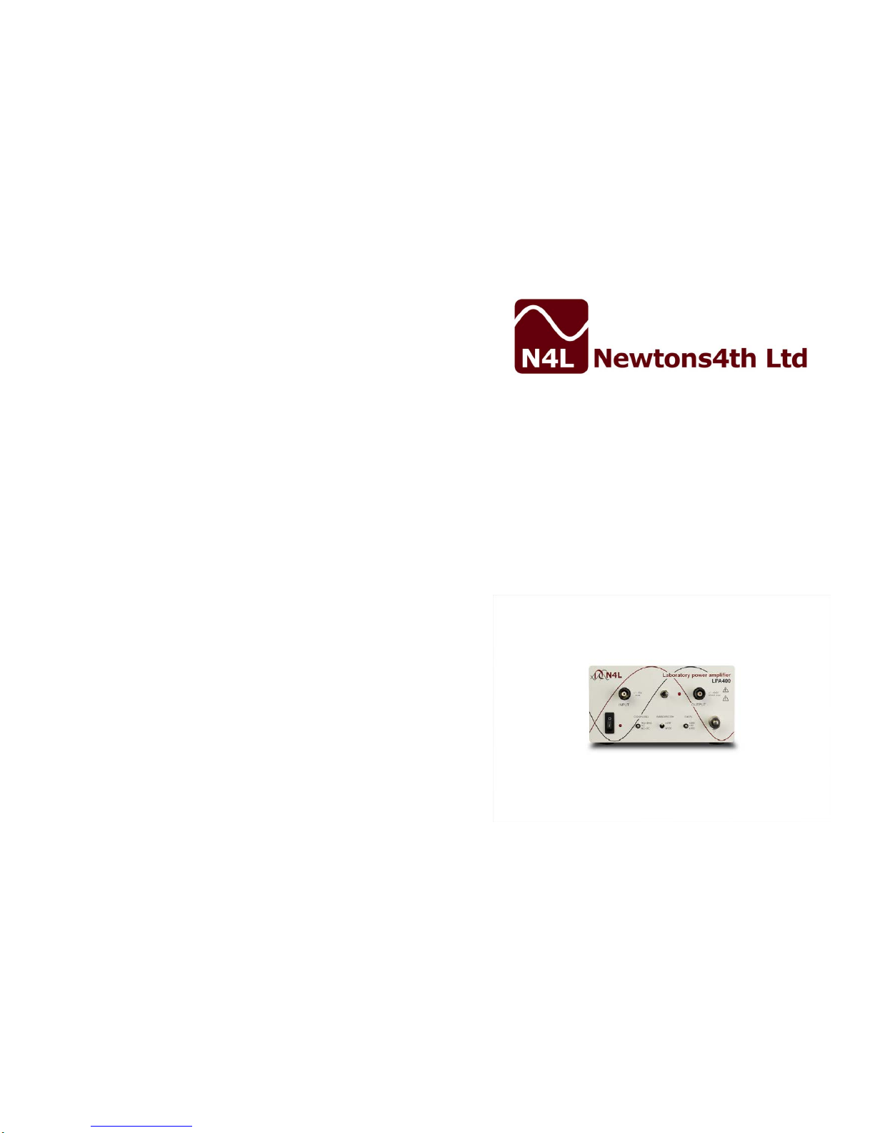
LPA400
Series.
Laboratory
Power amplifiers
USER GUIDE
Page 2

LPA400 User Guide
LPA400 series
High frequency, high voltage, dc accurate, power
amplifier for laboratory and industrial applications.
Description
LPA400 is a high frequency amplifier with up to ±400V peak voltage
output capability from dc to greater than 100 kHz. At lower output levels,
the gain extends beyond 1MHz. It uses an integrated po wer driver with
regulated high voltage supplies to give dc accuracy and excellent high
frequency performance, with high reliability.
The gain is switch selectable as x50, x200, or x500 and uses 0.1% low
temperature coefficient resistors for accuracy and thermal stability.
LPA400 is unconditionally sta ble driving resistive, capacitive (See note)
or inductive loads and can deliver up to 100mA rms continuously into any
load. An indicator on the front panel indicates that the output is on and
there is a switch to reset the protection circuitry in the event that it has
been triggered by excessive output current.
As well as ac and ac+dc coupling there is a special coupling mode, ac+
(dc), where the dc component is not eliminated entirely but is reduced by
a factor of about 10. This is particularly useful for testing wound
components with a controlled dc bias current where the dc resistance of
the component is considerably lower than the ac resistance. The high
frequency bandwidth can also be reduced with a low pass filter.
The LPA400 is housed in a robust steel cabinet and includes a current
overload reset switch.
LPA400 User Guide
Warranty
This product is guaranteed to be free from defects in materials and
workmanship for a period of 36 months from the date of purchase.
In the unlikely event of any problem within this guarantee period, first
contact Newtons4th Ltd. or your local repr esentative, to give a descrip tion of
the problem. If the problem cannot be resolved directly then you will be
given an RMA nu mber and as ked to return the unit. The unit will be r epaired
or replaced at the sole discretion of Newtons4th Ltd.
This guarantee is limited to the cost of the LPA400 itself and does not extend
to any consequential damage or losses whatsoever including, but not limited
to, any loss of earnings arising from a failure of the product.
In the event of any problem with the equipment outside of the guarantee
period, Newtons4th Ltd. offers a full repair service – contact your local
representative.
The LPA400 does not require any calibration.
Declaration of Conformity
We, Newtons4th Ltd, declare that the product LPA400, conforms to the
requirements of Council Directives:
89/336/EEC relating to electromagnetic compatibility:
EN 55022 Class A
73/23/EEC relating to safety of laborator y equipment:
EN 61010-1
January 2001
Eur Ing Allan Winsor BSc CEng MIEE
(Director of Newtons4th Ltd)
Newtons4th Ltd
1 Bede Island Road
Leicester
LE2 7EA, UK
Tel +44 116 2301066
Fax +44 116 2301061
e-mail [email protected]
Website www.newtons4th.com
Page 3

LPA400 User Guide
IMPORTANT SAFETY INSTRUCTIONS
This product can generate lethal voltages. Observe
all safety instr uctions.
This equipment is designed to comply with BSEN 61010-1 (Safety
requirements for electrical equipment for measurement, control, and laboratory
use) – observe the following precautio ns:
• Ensure that the supply voltage agrees wit h the rating of the instrument
printed on the back panel before connecting the mains cord to the supply.
• This appliance must be earthed. Ensure that the instrument is powered
from a properly grounded supply outlet.
• Use only safety connection leads approved to BSEN 61010-1.
• The input and output connectors, and the internal circuitry are isolated
from earth - do not exceed ±40V peak common mode.
• Keep all the ventilation holes on the underneath, rear, top, and sides free
from obstruction.
• Do not operate or store under conditions where condensation may occur or
where conducting debris may enter the case.
• There are no user serviceable parts inside the amplifier – do not attempt to
open the case, refer service to the manufacturer or his appointed agent.
Potentially lethal voltages are present insid e t he instru ment e ven when no input
signal is present.
• In the event of a failure of the mains fuse, disconnect the mains cord and
replace the fuse with the same type and rating, as shown on the rear of the
amplifier.
• Switch off the amplifier and ensure that the output curre nt has fallen to
zero before disconnecting an inductive load from the output.
Note: Newtons4th Ltd. shall not be liable for any consequential da mages,
losses, costs or expen ses arising from the use or misuse of this product
however caused.
LPA400 User Guide
Specification
Parameter
LPA 400A
LPA 400B
Units
Input connector
isolated BNC
Input impedance
10k
Ω
Peak operational input
voltage
±8 ±3.6
V
Maximum safe input voltage
±15
V
Input common mode range
±40
V
Input offset voltage
1.5
mV (typ) 5
mV(max)
Input coupling (switch)
ac, ac+dc, ac+(dc)
AC coupling filter –3dB
16
Hz
(DC) gain factor
0.1
Full power bandwidth
100K@800Vpk-
pk
1M@80Vpk-pk
200K@360Vpk
-pk
1M@80Vpk-pk
Hz (min)
Low bandwidth –3dB
(switch)
80k Hz
Low bandwidth filter
attenuation
40
dB/
decade
Low bandwidth filter type
linear phase
Gain options (switch)
x50, x200, x500
Low frequency gain accuracy
0.1
%
Output connector
isolated BNC
Peak output voltage
±400
±180
V
Peak output current
75
150
mApk
Continuous output current
50
100
mA rms
Maximum dc output current
70 @ >250Vdc
25 @ 0V
mA dc
Slew rate (Typical)
350
V/us
Output impedance
50
Ω
Temperature range
0 - 40
°
C
Size
8.5 x 15 x 25
cm
Weight
2.5
kg
Power source (UK)
(USA)
230V ±10%, 50Hz
115V ±10%, 60Hz
Power consumption
45
VA (max)
Notes:
All specifications at 230V, 50Hz, 23°C unless otherwis e stated.
All specifications are typica l v alues unless otherwise stated.
Derate output current linearly for output voltages between those s tated.
Page 4
LPA400 User Guide
Note: The amplifier contains an output r ms current protection circuit, and
when driving some capacitive loads this circuit may be activated. Due to
capacitor construction, at high cur rent the amount of e nergy transfer distorts
the current waveform resulting in ex cessive peak current (F ig 1 below), whilst
the rms value remains within specification. To ensure correct f unctionality and
prevent false triggering of the protection cir cuit, ideally the current w aveform
should be a sinewave as pictured in (Fig.2 below).
Fig 1 (Distorted current waveform)
Fig 2 (Correct current waveform)
LPA400 User Guide
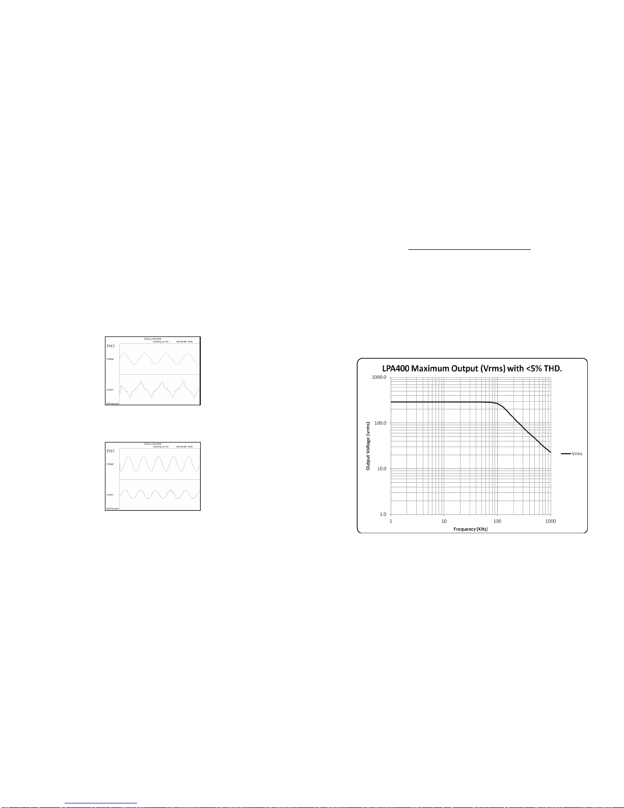
Total Harmonic Distortion:
For frequencies up to 50KHz, Total Harmonic Distortion is typically less
than 0.5%. Between 50KHz and 1MHz THD is typically less than 5%.
This graph demonstrates the effect of Total Harmonic Distortion on the
Maximum Output Voltage of the LPA400 amplifier at higher frequency
levels up to 1MHz.
 Loading...