

Page 1

OPERATOR’S MANUAL
VENTILATOR
6300A
NewTech Medical Limited
8400 Normandale Lake Boulevard, Suite 920,
Bloomington 55437, Minnesota, U.S.A
Tel: 1-952-837-2688 Fax: 1-952-400-8947
http://www.newtech-medical.com
E-mail: [email protected]
Page 2

CONTENTS
1 GENERAL ..........................................................................................................................................1
1.1 Main Technical Specification.......................................................................................................1
1.2 Operational environment requirements.......................................................................................2
1.3 Volume and weight......................................................................................................................2
1.4 Storage........................................................................................................................................2
1.5 Symbols.......................................................................................................................................2
2 SYSTEM OPERATION PRINCIPLE...................................................................................................3
2.1 System-Block-diagram................................................................................................................3
2.2 Basic Operation Principle............................................................................................................4
2.3 The rear panel.............................................................................................................................7
3 INSTALLATION AND CHECK............................................................................................................8
3.1 Ventilator Component..................................................................................................................8
3.2 Ventilator Installation...................................................................................................................9
3.3 Check ..........................................................................................................................................9
4 OPERATION.....................................................................................................................................11
4.1 Parameters’ setting....................................................................................................................11
4.2 Operation...................................................................................................................................12
5 OPERATION METHODS OF VARIOUS VENTILATION MODES ...................................................13
5.1 C: also called control respiration...............................................................................................13
5.2 A: Namely assist respiration......................................................................................................13
5.3 SIMV: Synchronization Intermission Mandatory Ventilation......................................................14
5.4 A/C+SIGH..................................................................................................................................14
5.5 SPONT......................................................................................................................................15
6 CLEANING AND MAINTENANCE...................................................................................................16
6.1 General principle.......................................................................................................................16
6.2 Maintenance..............................................................................................................................17
7 TROUBLESHOOTING .....................................................................................................................19
WARRANTY
Page 3

WARNINGS
The following warnings must be read and understood before performing any of the procedures
described in this section
z Under no circumstances should this medical device be operated in the presence of flammable
anesthetics or other volatile materials due to a possible explosion hazard.
z Lipid spilled or dripped into the unit may cause damage to the unit or result in an electrical
shock hazard.
z Oxygen vigorously accelerates combustion. Do not use any gauges, valves or other
equipment that have been exposed to oil or grease contamination to avoid violent ignition.
z When verifying the operation of this medical device, do not breathe directly from the machine.
Always use a fresh bacterial filter and test circuit. A hazard to the health of the service person
may result.
z Hazardous voltages exist within this medical device. Always observes appropriate safety
precaution when working on the unit while the machine is connected to an electrical power
source to prevent possible accidental injurious electrical shock.
z This medical device should never be serviced or the covers removed when connected to a
patient. Intern maintenance may affect the operation of the unit, jeopardizing patient care.
z Disconnect all electrical power, air and oxygen sources before attempting any disassembly.
Failure to do so could result in injury to the service technician and /or damage to the
equipment
z Removed and/or replaced. Failure to do so could result in malfunction of this medical device
and/or injury to the patient.
Page 4

IMPORTANCE
You are welcome to purchase and utilize our equipment.
The careful and comprehensive service to you is our commitment.
Please read thoroughly and carefully the Operation Manual before putting the machine into
operation and strictly follow all the procedures of operation.
Our company guarantees the quality of the product. Any time and in any case when you need our
help we are always ready to serve you.
One who is not authorized by our company shall not be allowed to open and dismantle the
machine.
Please directly contact Service Department in case of your need.
Page 5

6300A Operator’s Manual
- 1 - NewTech Medical Limited
1 GENERAL
6300A microprocessor ventilator is pneumatic driven, electronic-controlled, pressure-limit and timecycled multifunctional ventilator also with perfect multi-ventilating mode and monitoring system. Its
panel configuration refers to the figure.
1.1 Main Technical Specification
1.1.1 The performance of Airway System
a) Safety pressure of the airway system: no more than 6kPa;
b) Inspiration Fi - oxygen: no more than 45%
1.1.2 Ventilation mode
a) A/C
b) A/C+ SIGH
c) SIMV (f / 2, f / 4)
d) SPONT
1.1.3 Ventilation Performance
a) Respiration frequency f 6~60 times/min
b) I: E Ratio: 1:4, 1:3, 1:2, 1:1.5, 1:1,2:1, ±15%
c) Tidal volume 0, 80~1200mL, ±15%
d) Ventilating volume: >18L/min
1.1.4 Monitor Performance
a) Tidal volume digital display with error of ±20%
b) Ventilation frequency digital display
c) Airway pressure analogue display
1.1.5 Alarm Performance
a) Airway pressure high limit alarm 2~ 6kPa ±15%
b) Airway pressure low limit alarm 0~0.5kPa ±100Pa; 0.5 ~ 2kPa ±15%
c) Power-off alarm >120s
d) Silence <120s
1.1.6 Performance of the whole set
a) Power <50W
b) Noise of whole set <65dB(A)
c) Electrical safety Meet requirements for I type B mode equipment specified in IEC60601-1
<<Medical Electrical equipment: Part one: General requirement for safety>>
Page 6
6300A Operator’s Manual
NewTech Medical Limited - 2 -
1.2 Operational environment requirements
a) Ambient temperature +5 °C ~ +40°C
b) Relative humidity not more than 80%
c) Atmospheric pressure 86kPa ~104kPa
d) Requirements for Gas Source 0.3MPa ~0.5MPa, Oxygen
e) Power supply ~220V, 50Hz
f) Warming up no less than 5min
1.3 Volume and weight
a) Volume 376mm×246mm×196mm (L×W×H)
b) Weight 9kg
1.4 Storage
The product should be stored in the room with temperature of 0 ~ 40°C, relative humidity of no
more than 80%, good ventilation and without corrosion gas.
Note: When the storage conditions are beyond the requirements of operational environment, and
the storage state is transferred into operation state, the product only can be used after being stored
in environment for over 8 hours.
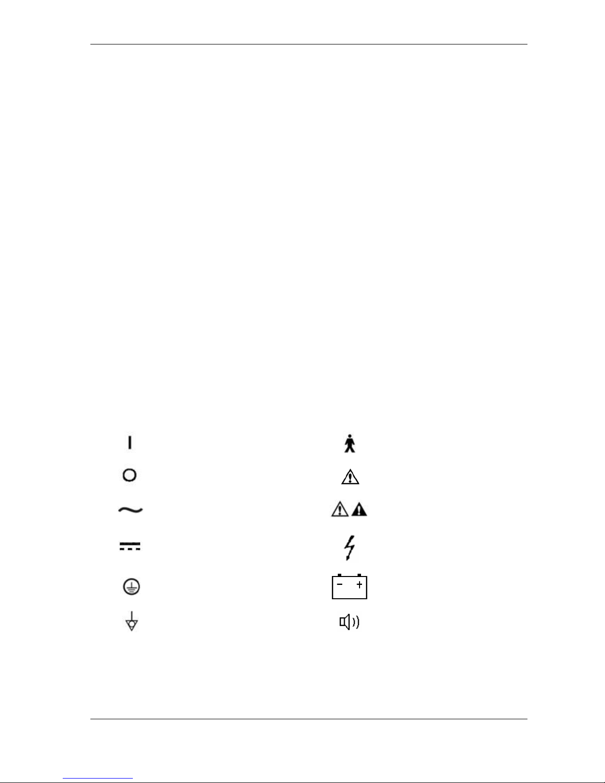
1.5 Symbols
ON (Power)
Type B equipment
OFF (Power)
Warning or Caution, ISO
7000-0434
Alternating Current
NOTE: refer to the manual,
IEC601-1
Direct Current
Dangerous Voltage
Protectively earth
Battery
Equipotential
Buzzer
Page 7
6300A Operator’s Manual
- 3 - NewTech Medical Limited
2 SYSTEM OPERATION PRINCIPLE
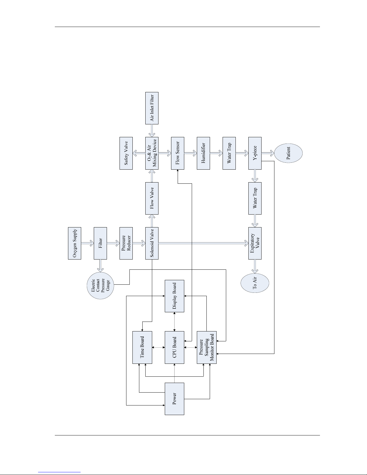
2.1 System-Block-diagram
Figure 2-1 6300A Diagram
Page 8

6300A Operator’s Manual
NewTech Medical Limited - 4 -
2.2 Basic Operation Principle
The high-pressure oxygen enters the pressure reduction valve I, and the output pressure from the
pressure reduction valve I is stabilized at 0.25MPa (already adjusted before ex-factory). The output
gas from the pressure reduction valve I enters the electromagnetic valve. In inspiring, the
electromagnetic valve is open; the two-way outputs enter the flow valve and the pressure reduction
valve II respectively. The one entering the pressure reduction valve II presses on the diaphragm in
the expiration valve by means of the gas pressure to control the opening and closing of the
expiration valve, and the output pressure is stabilized at 0.05MPa (already adjusted before exfactory). The other one enters the flow valve. The tidal volume value could be changed through
adjusting the flow valve. The pure oxygen entering the gas line is mixed in accordance with a
certain proportion in the gas room. The air enters from the venturi-type valve, and a unidirectional
valve is installed in the venturi-type valve to prevent the gas overflowing. The sponge gas entrance
is adopted for the unidirectional valve to reduce noise and filtrate the gas to be breathed in. A
safety valve is installed on the side face of the gas room to prevent that the air pressure is too high
and will make hurt to a patient. When the air pressure exceeds the set value of the safety valve
(5.1kPa~6kPa), the safety valve can open automatically and the gas will be discharged from the
safety valve. The electromagnetic valve will be closed in expiration, the pressure exerted on the
diaphragm of the expiration valve will disappear, and the diaphragm will loose. Thus the gas room
connects with the atmosphere directly. The gas compressed in the bellows by the ventilator will
discharge to the atmosphere through the expiration valve. The process above will be repeated
along with the breath rhythm.
During the above procedures, it is the electromagnetic valve that controls the gas flowing direction,
and is controlled by the mainframe board. In inspiration the electromagnetic valve will be opened
while in expiration it will be closed. In the Fig. 2, the display plate is used for the digital display for
the respiration rate, breath frequency, the tidal volume and the oxygen concentration, the display of
the corresponding display lamps and the display of the luminous line of the pressure. The
mainframe board is the central processing unit of the ventilator circuit part. It not only controls the
opening and closing of the electromagnetic valve, but also receives and processes the pressure
signal, the flow signal. It receives the inputs from the panel and sends the signal that will be
outputted to display to the display plate. The voltage stabilizing power supply provides the circuit
needed voltages (+5V, +12V, −12V). The functions of the subsystems above are set and adjusted
by the keys on the panel.
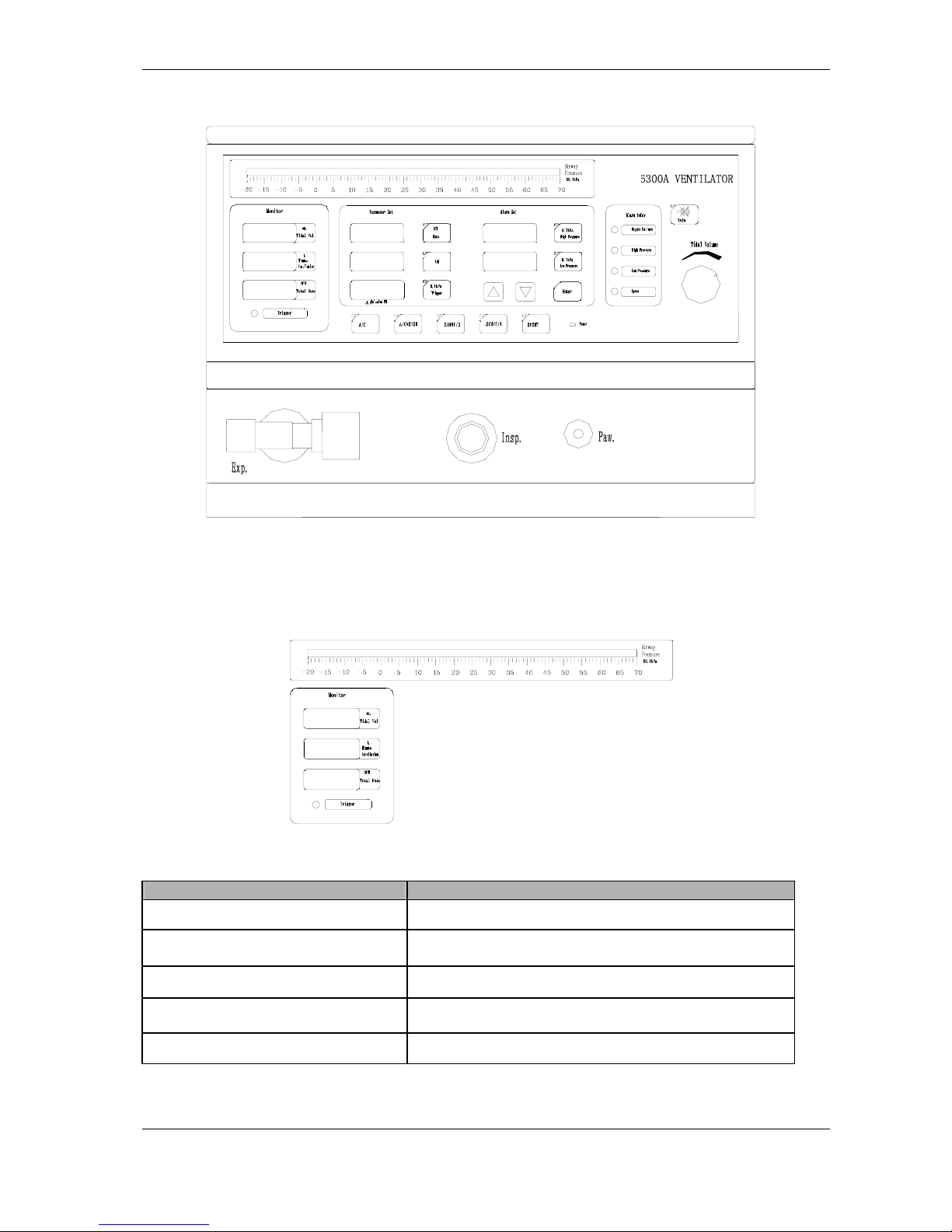
The front and back panels drawings of the ventilator are shown in Figure 2-2, Figure 2-3.
Page 9
6300A Operator’s Manual
- 5 - NewTech Medical Limited
The front panel
Figure 2-2
2.2.1 Display screen
See Fig. 4. Table1
Figure 2-3
Table 2-1
Display symbol’s implication Function
TIDAL VOL Display the tidal volume value.
AIRWAY PRESSURE
Airway pressure display: Reflect the airway pressure
change when patients respiration.
MV Display minute ventilation
TOTAL Total frequency display.
TRIG PRESS Trigger display.
Page 10
6300A Operator’s Manual
NewTech Medical Limited - 6 -
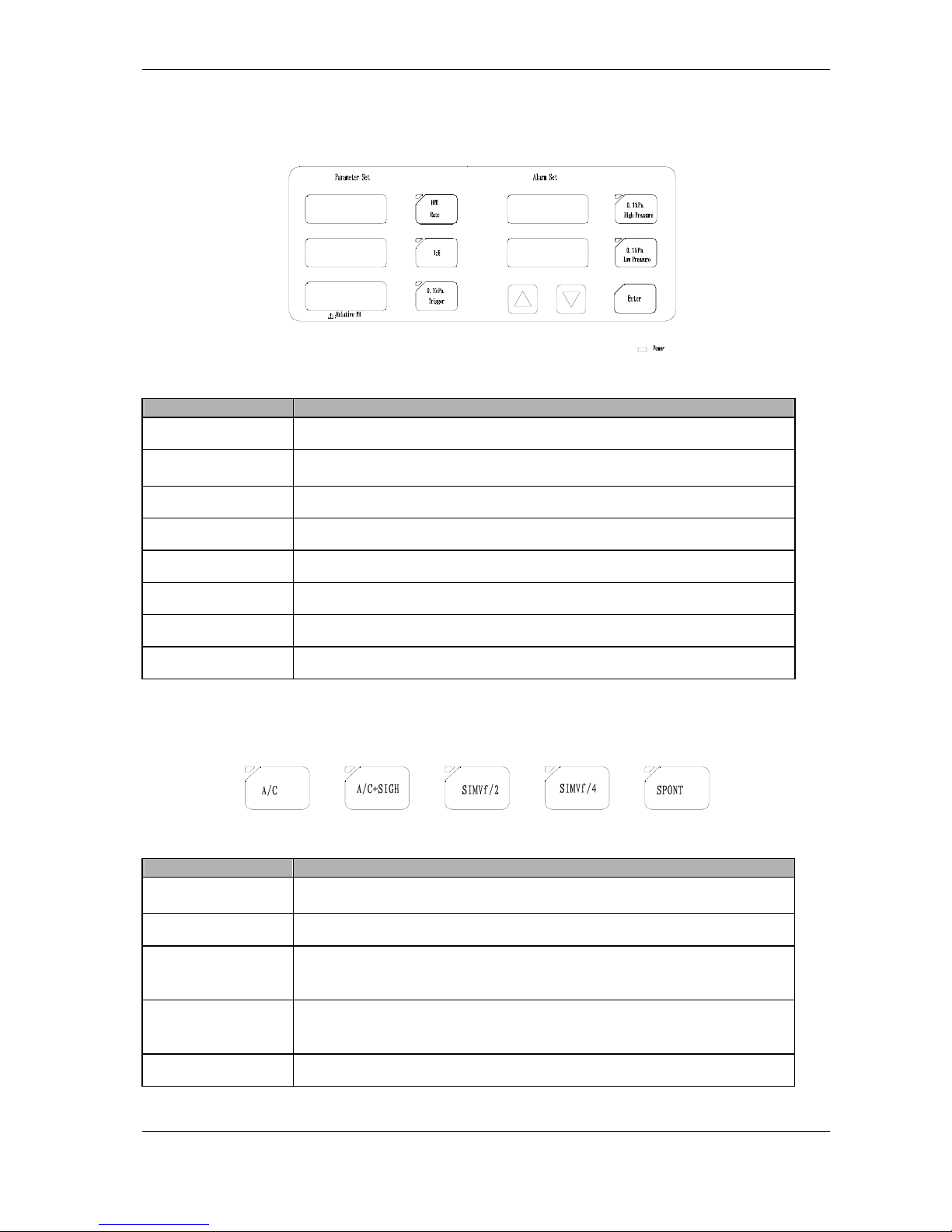
2.2.2 Parameter setting key
Figure 2-4
Table 2-2
Parameter Function
RATE Respiratory frequency setting key ranging from six to sixty bpm.
I: E
Inspiration and respiratory ratio setting key, totally six positions:
1:4, 1:3, 1:2, 1:1.5, 1:1, 2:1.
TRIG PRESS Trigger pressure setting key.
Δ
Increase each parameter’s value on screen. (Increasing key)
∇
Decrease each parameter’s value on screen. (Decreasing key)
HI PRESS High airway pressure limit setting key.
LO PRESS Low airway pressure limit setting key.
POWER
Power Indicator.
2.2.3 Function key
Figure 2-5
Table 2-3
Symbol Function
A/C
Intermittent positive pressure ventilating key. Synchronous intermittent
positive pressure ventilating key.
A/C+ SIGH Sigh key.
SIMV f/2
Synchronous intermittent positive pressure mandatory ventilating key, at
this moment, the respiratory frequency is one-second of the A/C
ventilating frequency.
SIMV f/4
Synchronous intermittent positive pressure mandatory ventilating key, at
this moment, the respiratory frequency is one-fourth of the A/C ventilating
frequency.
SPONT Spontaneous ventilation key.
Page 11
6300A Operator’s Manual
- 7 - NewTech Medical Limited
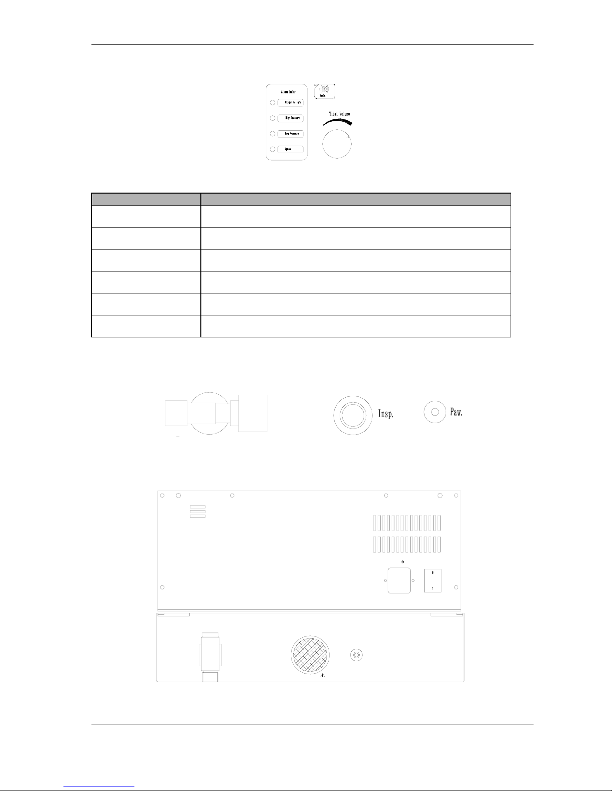
2.2.4 Alarm Information Display
Figure 2-6
Table 2-4
Symbol Function
Oxygen Failure
Supply Oxygen Failure Alarm Display.
HI PRESS
Airway High Pressure Alarm Display.
LO PRESS Airway Low Pressure Alarm Display.
Apnea Apnea Alarm
Tidal Volume Tidal volume regulating knob. Regulate ranging :0, 80ml~1200ml
2min Eliminate alarm. When alarming, press the key to eliminate alarm.
2.2.5 Others
Figure 2-7
2.3 The rear panel
Oxygen
Do Not Block
Air Inlet
Pressure Relief Valve
Power Switch250V0.5A 5X20(T)
Beep
名称:呼吸机
出厂日期:
地址:北京市石景山区八大处高科技园区双园路9号
北京谊安世纪医疗器械有限公司
出厂编号:
型号:
产品注册号:
功率:
频率:
电压:
Figure 2-8
Page 12
6300A Operator’s Manual
NewTech Medical Limited - 8 -
3 INSTALLATION AND CHECK
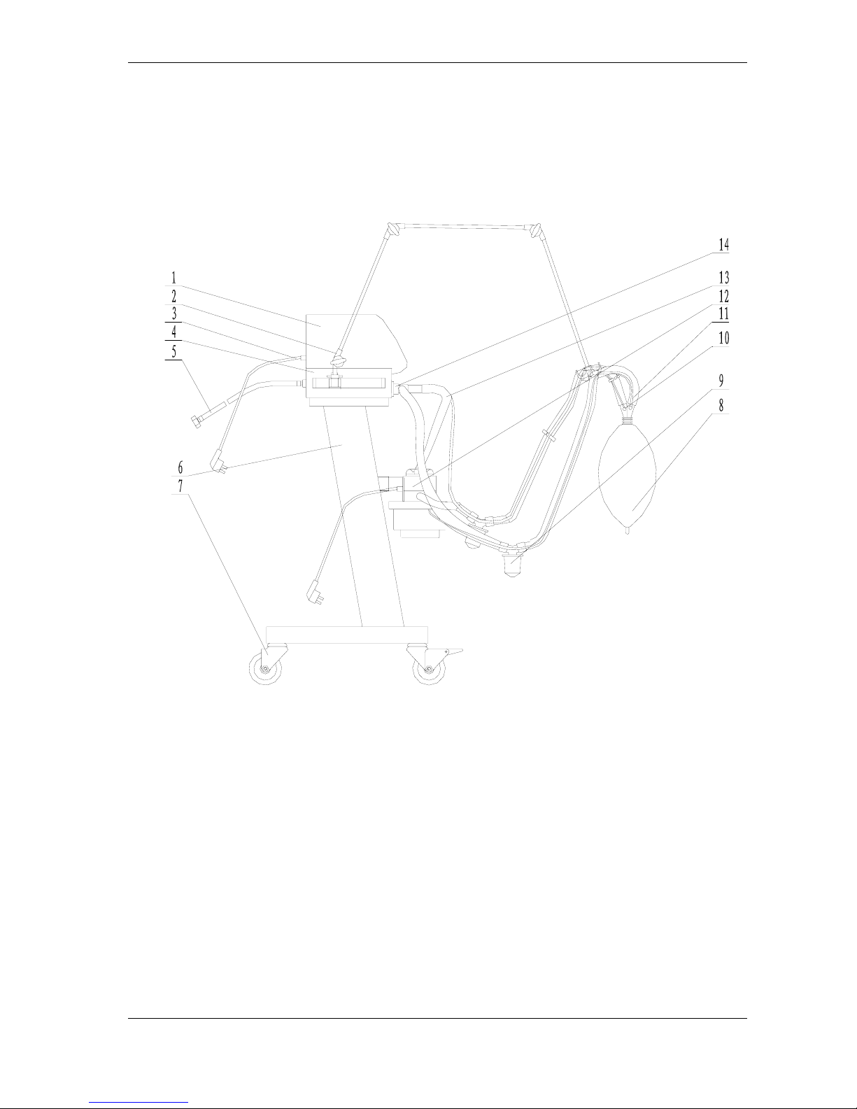
3.1 Ventilator Component
Figure 3-1
1 Ventilator
2 Machine Arm
3 Power Cable For Ventilator
4 Check Valve
5 Oxygen Pipeline
6 Cart
7 Wheels
8 Bag
9 Water Trap
10 Lines For Measure Temperature
11 Pressure Sampling Tube And Joint Of Y Pipe
12 Humidifier
13 Threading Pipe
14 Respiratory Valve
Page 13

6300A Operator’s Manual
- 9 - NewTech Medical Limited
3.2 Ventilator Installation
3.2.1 Take out all parts of ventilator from the box
3.2.2 Main-machine connection
See Figure 3-1
3.2.3 Power supply connection
There is a power socket box behind the cart of the ventilator, whose input cable plug of 3m long
can be connected to the power (~220V, 50Hz) socket of the ward, while the ventilator power plug,
humidifier plug, monitor (optional) power plug is plugged in the power socket. After it is turned on,
the indicating lamp will light up, the voltmeter will indicate the voltage value. The 6300A ventilator is
used under the ~220V ±10% power supply. If the power supply voltage in the ward varies greatly,
a voltage-stabilizing power supply should be used.
The fuse of the 6300A ventilator is at the power socket position of the rear panel. The fuse, with the
value of 2A, can be replaced after the power cable is unplugged and the fuse box rear cover is
opened with a small dash-line screwdriver.
3.2.4 Gas source connection
The 6300A ventilator need compressed oxygen for operation. For the hospital with centralized
oxygen supply, the pipe can be connected to the air and oxygen socket on the wall directly. For the
hospital without centralized oxygen supply, generally the compressed oxygen is obtained from the
oxygen bottle, with a pressure reducer connected to the output of the oxygen bottle.
3.3 Check
3.3.1 Ventilator and relevant parts’ check
Operators should check the machine before operating the ventilator to ensure the perfect.
3.3.2 Power-off alarming check
Switching on the ventilator’s power, then off, should cause sound alarm.
Page 14

6300A Operator’s Manual
NewTech Medical Limited - 10 -
3.3.3 Switch on the ventilator’s power
Set the ventilator standard state
Upper pressure limit at 6kPa
Lower pressure limit at 0.5kPa
The respiratory frequency at 20bpm
The ventilation mode as A/C
I: E as 1:2
The tidal volume 700ml
3.3.4 Airway upper pressure limit alarming function check
Adjust the upper pressure setting key, the display value is a little lower than the airway pressure
peak value, set out the sound-light alarm, then the machine turns into respiration immediately with
decrease of the airway pressure.
3.3.5 Airway lower pressure limit alarming function check
Take off the inspiration channel hose. After ten to fifteen seconds sound-light alarm occurs.
3.3.6 Trigger pressure check
Set the trigger pressure at 0.1cm H2O. Pinch the simulated lung with both hands. When the airway
pressure is a little lower than the preset value, trigger inspiration and the indicating light to flash.
3.3.7 SIMV (f/2, f/4) function check
Set the respiratory frequency at twenty times/min. and the ventilating mode as A/C. Choose the
respiratory function to be SIMV f/2 or SIMV f/4. After one minute, observe TOTAL reading ten
times/min. or five times/min.
3.3.8 Spontaneous function check
Set the function at Spontaneous and the trigger voltage at -3cmH2O. Pinch the simulated lung with
hand to form negative pressure; at this time the ventilator should deliver gas. When airway
pressure reaches 3cmH
2
O, start ventilation.
3.3.9 A/C+SIGH function check
First set the ventilating mode as A/C, turn the flow regulating knob to the minimum, then change
the ventilating mode to SIGH, following that is one sigh with 1.5 times of the tidal volume.
Page 15

6300A Operator’s Manual
- 11 - NewTech Medical Limited
4 OPERATION
This chapter will mainly introduce the detailed operating method of 6300A ventilator.
4.1 Parameters’ setting
Table 4-1
Parameter key Operating method
Tidal Volume
Turn the knob to change the tidal volume value. Increase by clockwise
and decrease by counter-clockwise.
I: E
Inspiration and respiratory ratio setting:
When pressing I: E key, the light at the left upper corner of the key flashes
and the revised part flashes. At this moment press Δ or ∇ key, and set the
I: E mode.
RATE
Respiratory frequency setting:
When pressing RATE key, the light at the left upper corner of the key
flashes and the revised part flashes. At this moment press Δ or ∇ key, and
set the respiratory frequency.
HI PRESS
Airway upper pressure limit setting:
When pressing HI PRESS key, the light at the left upper corner of the key
flashes and the revised part flashes. At this moment press Δ or ∇ key, and
set the airway upper pressure limit.
LO PRESS
Airway lower pressure limit setting:
When pressing LO PRESS key, the light at the left upper corner of the
key flashes and the revised part flashes. At this moment press Δ or ∇
key, and set the airway lower pressure limit.
TRIG
Trigger pressure setting:
When pressing TRIG key, the light at the left upper corner of the key
flashes and the revised part flashes. At this moment press Δ or ∇ key, and
change the trigger pressure value.
2min
Eliminate alarm
When alarming, press the key to eliminate alarm.
Page 16

6300A Operator’s Manual
NewTech Medical Limited - 12 -
4.2 Operation
Table 4-2
Parameter key Operating method
A/C
Control ventilation:
When pressing the key, the light at the left upper corner of the key
flashes. At this mode, in case of the patients’ respiratory condition,
ventilate for the patients according to the pre-adjusted ventilating
parameters.
Assist ventilation:
When pressing the key, the light at the left upper corner of the key
flashes. At this mode, inspiration depends on patients. Other parameters
ventilate for the patients according to the pre-adjusted ventilating
parameters.
A/C+ SIGH
Sigh:
When pressing the key, the light at the left upper corner of the key
flashes. During A/C, every certain time provide double tidal volume
once.
SIMV f/2
Synchronous intermittent mandatory ventilation:
When pressing the key, the light at the left upper corner of the key
flashes. Patient controls the spontaneous respiration frequency, but the
value is one-second of the preset A/C frequency.
SIMVf/4
Synchronous intermittent mandatory ventilation:
When pressing the key, the light at the left upper corner of the key
flashes. Patient controls the spontaneous respiration frequency, but the
value is one-fourth of the preset A/C frequency.
SPONT
When pressing the key, the light at the left upper corner of the key
flashes. The patient spontaneous respiration via continuous positive
pressure gas flow system.
Page 17
6300A Operator’s Manual
- 13 - NewTech Medical Limited
5 Operation Methods of Various Ventilation
Modes
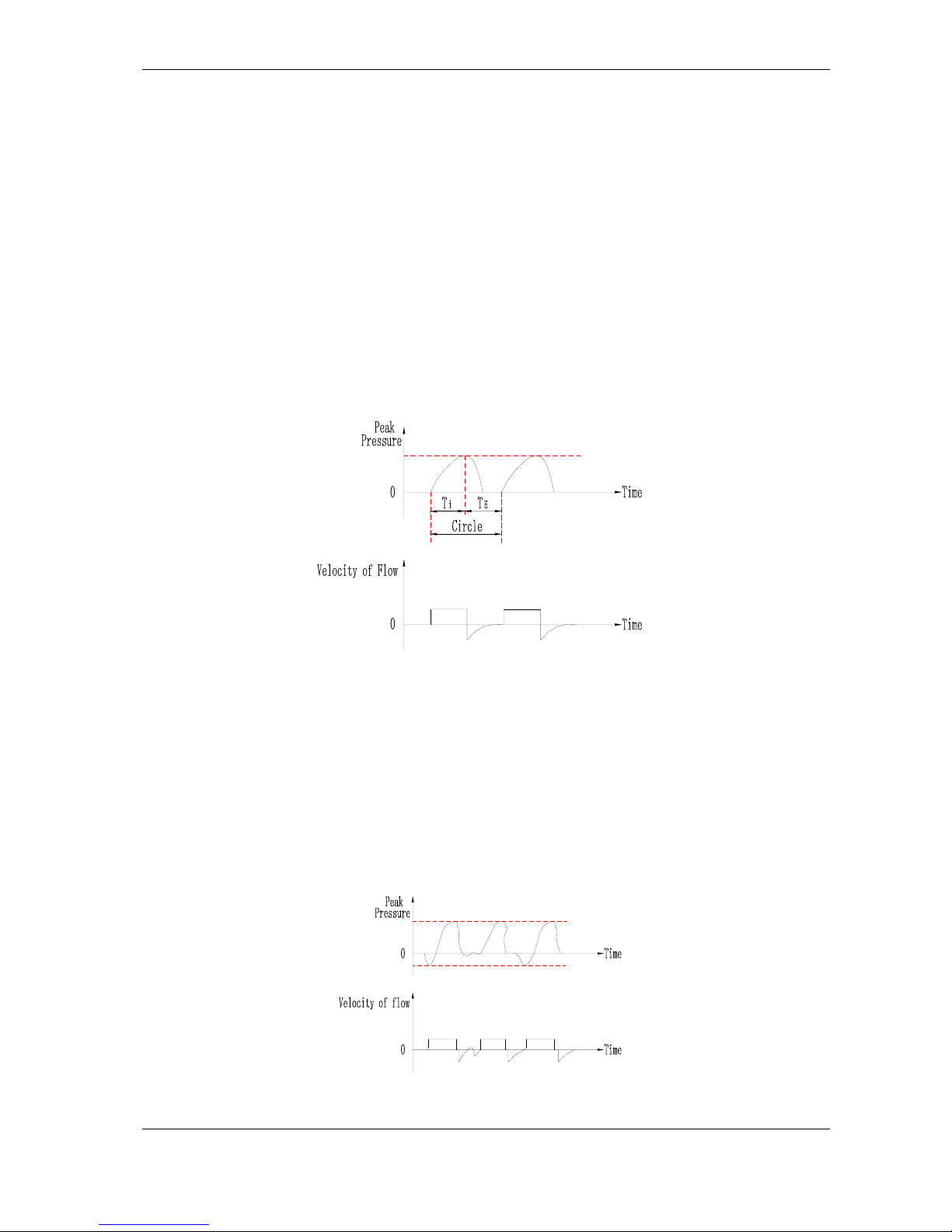
5.1 C: also called control respiration
The characteristic is that patient cannot control releasing airflow, and all respiratory movement all
must be carried out according to the conditions set by ventilator.
Operation methods is as following:
a) Set the breath frequency f.
b) Set the ventilation volume
c) Upper limit setting for airway pressure: it can be set higher when turn on the ventilator, read the
airway pressure peak value from the airway manometer after ventilator runs normally in A/C mode,
then set the upper pressure limit 1kPa higher than the airway pressure peak value.
Figure 5-1 Control Ventilation Waveform
5.2 A: Namely assist respiration
It is featured by that the patient can control the respiration frequency, while the tidal volume of the
respiration, the time of the inspiration and expiration are still controlled by ventilator. To the patients
who remain fully conscious and have spontaneous respiration ability, but can’t conduct enough
breath function, the assist respiration of the ventilator is needed.
a) Control the ventilation frequency f, the set value should be lower several times every minute
than f
total,
b) Set the burst electrical level: adjust around –0.3kPa.
To A, several above-mentioned parameters must be adjusted properly and must assist with vigor
analysis. Other parameters adjustments are all same to C.
Figure 5-2 Assist Respiration Waveform
Page 18
6300A Operator’s Manual
NewTech Medical Limited - 14 -
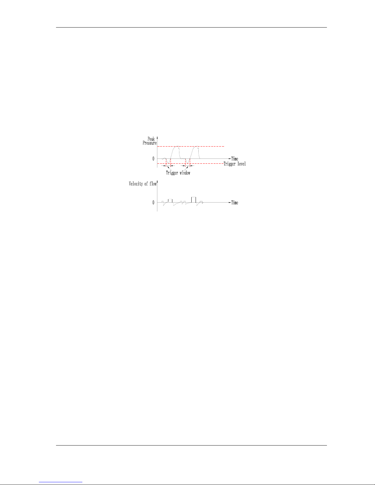
5.3 SIMV: Synchronization Intermission Mandatory Ventilation
This is a kind of method combined by patient independence breath and machine mandatory
ventilation. The mandatory ventilation is touching off synchronous. It is used in the procedure from
mandatory ventilation to independence breath before carrying down machine.
a) SIMV f/2: mandatory ventilation frequency is one half of A/C ventilation frequency. The
mandatory ventilation of SIMV and independence breath is both touch off synchronous with patient,
so the touch off electrical level should be set. Normal it is adjusted around –0.3kPa. The
independence breathe when
Other parameter settings are same as that of A/C.
b) SIMV f/4: The command ventilation frequency is one fourth of A/C ventilation frequency. Others
are same as that of f/2.
Figure 5-3 SIMV Waveform
5.4 A/C+SIGH
SIGH is that on the basis of A/C make a deep inspiration of double tidal volume every 100 times,
which is adapted to the long term mechanically ventilation patient and can be used in “expanding
lung” of thorax operation. When expanding lung, because requires continuous several sighs it is
needed to convert ventilation method conversion switch several times between A/C and SIGH.
When signing because tidal volume is doubled and the peak value of airway press increases, the
upper limit set value of airway press will increase. That is the peak value is higher 1kPa than the
value of sighing, the set of other parameters are same to A/C.
Page 19
6300A Operator’s Manual
- 15 - NewTech Medical Limited
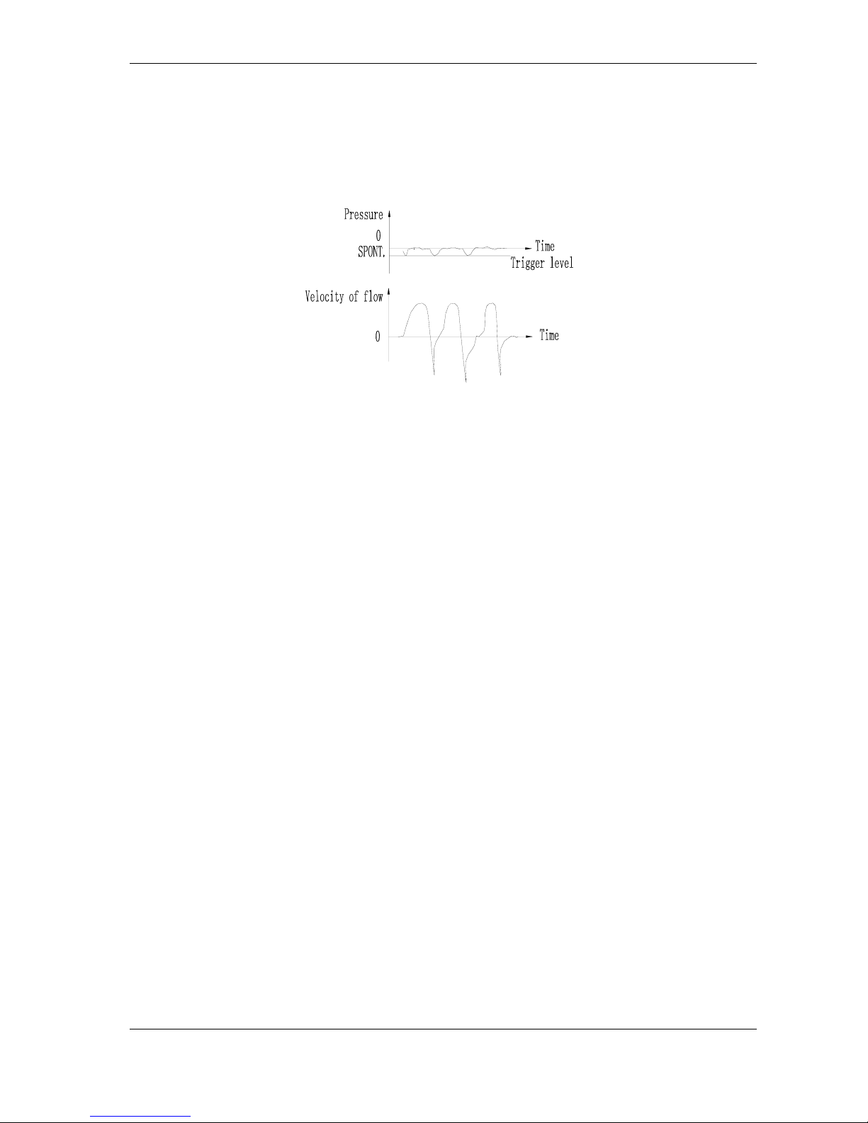
5.5 SPONT
In some hospitals, after patient have spontaneous respiration, select SPONT should be provided
for the patient through facemask before offline so as to train the spontaneous respiration ability of
the patient. As a routine, the methods for realizing persistent gas flow are as follows:
Figure 5-4 Spontaneous Waveform
Page 20

6300A Operator’s Manual
- 16 - NewTech Medical Limited
6 CLEANING AND MAINTENANCE
6.1 General principle
Generally, the gas in the inspiration circuit (the part before the humidifier) is dry and clean, and
flows to the patient with a certain velocity, so it is unsuitable for the bacteria to grow. While the gas
in the expiration circuit is from patient, it is humid, and some patients have infectious disease,
which is easy for the bacteria to increase, so the cleaning and disinfectant operations are specified
in principle as follows.
6.1.1 Non-infective patient
Just conduct disinfectant for the connectors such as patient circuit (silicon rubber threaded pipe),
water trap and Y joint out of the airway for each patient. The disinfectant method can be fumigating,
infection liquid soaking or high-temperature sterilization, decided in accordance with the hospital's
conditions.
6.1.2 Infective patient
Besides conducting disinfectant for the patient circuit, the gas delivery element (in the airway tank)
of the expiration circuit should also be disinfected so as to avoid cross infestation between patients
and prevent the ward from being polluted so that the health of staffs is affected. Refer to the above
for the disinfectant method. But the flow sensor should be paid special attention, as it is precision
and damageable part. For disinfectant, it is better to soak it in alcohol for an hour, and then dry it.
While soaking, the plug part of the sensor should be upward and exposed in the air, it will be OK if
the alcohol height can drown the ventilation hole. When positioning the disinfected sensor, pay
attention to positioning the side marked with arrowhead upward (the arrow head means the flow
direction).
6.1.3 Surface cleaning and sterilization
Clean the machine's panel and all surfaces with soft cloth soaked with the soluble sterilizing agent.
The formation and preparation of the agent must be done in accordance with the direction given by
the manufacturer. One must prevent the sterilizing agent drops from entering the anesthetic
machine and the misusage of organic agent for cleaning the machine.
6.1.4 Expiratory valves cleaning
Dismount the cover of the expiratory valves by rotating it counter clockwise, then clean all parts of
them with the gauze socked with water soluble sterilizing agent, after all parts cleaned and dried
recover it in original integration. Then one must check the leakage and the movement of the
expiratory valves in accordance with the required regulation and checking procedure. Please
handle all parts with care preventing any damage.
Page 21

6300A Operator’s Manual
- 17 - NewTech Medical Limited
6.2 Maintenance
6.2.1 Maintainability
The 6300A ventilator is designed to place reliability at the principal position, and it is required that
the mean time of break free (MTBF) of the whole machine be greater than 2000 hours. But human
operates the machine; the operating life of the machine in a great extent is dependent on the
human factors. Correct operation and careful maintenance will greatly prolong the life of the
machine, and reduce the appearance of faults. The repairing operation is divided into maintenance
and repair. By maintenance it is meant the fault location and removing after fault appears. The
repair is under the charge of the repairing personnel from the factory or specified maintenance
point; the user should not carry out repairing by him. For the doctor or nurse who operates the
ventilator, stress should be laid on the regular maintenance of the machine.
6.2.2 Disinfect, cleaning, drying and correctly install of the easy
damageable part.
The pipeline for connecting the machine and patient is easy to be polluted, so disinfectant is
needed, and the method is shown in the operation manual. The airway channel、connector and
sensor, etc. After disinfectant should be correctly installed in position without gas leakage. After
installation, trial running should be conducted, and the machine can be connected to patient and
used only after it is operated normally. It should be specially specified that the arrowed head on the
flow sensor means the flow direction, and it should not be installed in reverse. Also the sensor of
the inspiration circuit and that of the expiration circuit can’t be mistaken. Generally, the expiration
channel is easy to be polluted, thus just disinfecting the expiratory flow sensor is OK. After
disinfectant and cleaning, it must be dried, otherwise, if there is water on the wire mesh, the
resistance will increase, the expiration flow will become inaccurate, thus the reading on the expired
minute volume meter will be affected.
Those parts that directly touch the patient's body are easily polluted, the sterilization must be done
after every use as explained before. It must be here emphasized is that: One must do strictly the
correct installation after every cleaning and sterilization. The recovered machine must be tested
and ensured in good condition before putting in reuse for patients.
6.2.3 Maintaining good contact for connectors
The connector comprises airway connector and circuit connector. For all the joints, rubber
connectors and delivering pipes of the airway, good contact should be ensured so as to guarantee
the gas circulating without gas leakage. For all the connectors in the circuit, check should be
conducted before operation, especially connectors of inspiration valve and expiration valve, as they
have no locking device, main check should be carried out to prevent them from loosening.
6.2.4 Correctly operation of panel knob
The panel knob should be operated carefully with slight motion. In special, the potentiometer knobs
should not be screwed with force when the terminal position is attained as this may lead to
dislocation. After dislocation, the set value is not accurate, which even may cause abnormal
operation of the machine.
Page 22

6300A Operator’s Manual
- 18 - NewTech Medical Limited
6.2.5 Maintenance during operation and transportation
The location of the machine at the operation place (such as operating room, ward, monitor room)
should be appropriate, so that the doctor or nurse may not touch the machine during operation,
therapy or nursing of the patient. Special the airway pipeline and power supply cable on the ground
should not affect walking of person so as to avoid them being contacted and causing gas and
electricity failure. The knob on the panel should not be misplaced due to involuntary contact to
make the set value abnormal. In transporting the machine, especially going up and down the stairs,
it should be protected to avoid the cart from dumping and damaging the valuable machine.
Page 23

6300A Operator’s Manual
- 19 - NewTech Medical Limited
7 TROUBLESHOOTING
Table 7
Troubles Causes Methods
Corrugated hose damaged o
r
connector loose
Replace or reinstall properly
Sensor connector loose Reinstall
Patients’ respiratory loop leaks Check as the above method
Patients breathing system
leaks
Flow regulating switch closes Turn on the flow regulating
switch
Pressure is too high in
pneumatic system under
“ Manual breathe”
Semi-tight valve regulated
improperly
Regulate again properly
Ventilator doesn't work
normally
Source pressure is too low Regulate source pressure
Power off Switch on the power source
Digital number tube
doesn’t flash,
Ventilator doesn’t work
Fuse melts Replace
During operation,
ventilator stops suddenly,
indicating light goes out
with sound-alarm
Power off
Shift to be artificial ventilating
mod
Airway upper pressure limi
t
setting too low
Reset
Upper airway pressure
limit alarms
Airway block Remove
Airway lower pressure limi
t
setting too high
Reset
Airway leaks or hoses and
channels loose
Check or reconnect
Lower airway pressure
limit alarms
Patients’ compatibility changes
Pressure sensor connecting
hose loose
Reconnect
Pressure displays zero or
no readings
Pressure sampling hole blocks Remove
Flow sensor damaged Contact our company
Tidal volume displays
lower or doesn’t display
Ventilator in trouble Contact our company
Page 24
6300A Operator’s Manual
NewTech Medical Limited - 20 -
VENTILATOR
WARRANTY
NewTech Medical Limited (NewTech) guarantees to the customers
that NewTech VENTILATOR machines to be free from defects for a
period of eighteen (18) months and accessories for a period of three
(3) months. The warranty period starts at the date of purchase.
The warranty is void if the ventilator machines have not been used
in accordance with the operation manual or improperly
disassembled by anyone other than NewTech.
Vinson Lau-President
NEWTECH MEDICAL LIMITED
Http://www.newtech-medical.com
 Loading...