


SHAPING THE FUTURE OF SATELLITE COMMUNICATIONS
User Manual
for
AZ710 Up Converter
version 1.2

User Manual for AZ710 Up Converter
version 1.2
i
SHAPING THE FUTURE OF SATELLITE COMMUNICATIONS
© 2008 Newtec cy.
The material contained in this document is confidential and intended for use only
by parties authorised by Newtec.
All Rights Reserved. No part of this document may be photocopied, reproduced,
stored in a retrieval system, or transmitted, in any form or by any means whether,
electronic, mechanical, or otherwise without the prior written permission of Newtec
cy.
Newtec cy
Laarstraat 5
9100 Sint-Niklaas, Belgium
General: +32 (0)3 780 65 00
www.newtec.eu
Fax +32 (0)3 780 65 49
General:
general@newtec.eu

Compliancy Statements
User Manual for AZ710 Up Converter
version 1.2
ii
SHAPING THE FUTURE OF SATELLITE COMMUNICATIONS
COMPLIANCY STATEMENTS
TO WHOM IT MAY CONCERN
EC DECLARATION OF CONFORMITY
We,
NEWTEC CY nv.
Declare that the following product:
Product number: AZ710
with type identifier: ntc2142
to which this declaration relates is in conformity with the essential requirements of
European Union Directive 1999/5/EC Radio and Telecommunication Terminal
Equipment Directive Essential Requirement 3.1(a), 3.1 (b), 3.2.
Done at St-Niklaas, on 26 November 2008
Serge Van Herck,
CEO
NEWTEC CY nv. Laarstraat 5 B-9100 Sint-Niklaas Belgium.
Tel:0032.(0)3.7806500 Fax:0032.(0)3.7806549

Compliancy Statements
User Manual for AZ710 Up Converter
version 1.2
iii
SHAPING THE FUTURE OF SATELLITE COMMUNICATIONS
TO WHOM IT MAY CONCERN
Restriction of Hazardous Substances Directive (RoHS)
(Directive 2002/95/EC)
The undersigned hereby confirms the following statement:
We hereby declare that all Newtec equipment, delivered after July 1, 2006 and
used in network infrastructure equipment for switching, signalling or transmission
will be compliant to the RoHS Directive 2002/95/EC. We hereby take into account
the exemption for the use of lead in solders as specified in the annex of the
Directive. This exemption is further clarified in a study ordered by the European
Commission “Technical adaptation under Directive 2002/95/EC (RoHS) –
Investigation of exemptions (ERA Report 2004-0603, ERA Project 043121279)”
Newtec is making serious efforts to completely ban lead in solders throughout its
entire product range and in the shortest possible timeframe. If you have
applications where you intend to use Newtec equipment in an infrastructure other
than network infrastructure for switching, signalling or transmission, please do not
hesitate to contact us. As in time more and more Newtec equipment will be totally
leadless, we will inform you on the status of the equipment you intend to use at that
time.
Done at St-Niklaas, on 26 November, 2008
Serge Van Herck,
CEO
Safety Regulations
User Manual for AZ710 Up Converter
version 1.2
iv
SHAPING THE FUTURE OF SATELLITE COMMUNICATIONS
SAFETY REGULATIONS
Please read this chapter before you install and use this equipment.
To ensure your safety, the equipment has been designed to comply with the
following safety standard:
IEC 60950 Safety of Information Technology Equipment
Before you start to install and operate the device, please make sure you observe
the following:
The equipment described in this manual is designed to be used by properly trained
personnel only. Only qualified personnel who are aware of hazards involved may
adjust, maintain and repair the exposed equipment.
No operator serviceable parts inside. Refer servicing to qualified
personnel. To prevent electrical shock, do not remove covers.
To use the equipment correctly and safely, it is essential that both operating and
servicing personnel follow generally accepted safety procedures in addition to the
safety precautions specified in this manual. Warning and caution statements and/or
symbols are marked on the equipment when necessary. Whenever it is likely that
safety protection is impaired, immediately switch off the equipment and secure it
against unintended operation. Inform the appropriate servicing authority about the
problem. For example, safety is likely to be impaired if the equipment fails to
perform the intended measurements or shows visible damage.
Caution1:
FOR CONTINUED PROTECTION AGAINST FIRE, REPLACE
LINE FUSES ONLY WITH SAME TYPE AND RATING (5 X 20mm
T3.15 A/250v TYPE T or slow-blow).
Caution 2:
THERE IS RISK OF EXPLOSION IF THE BATTERY IS
REPLACED WITH AN INCORRECT TYPE. DISPOSE OF USED
BATTERIES ACCORDING TO THE INSTRUCTIONS.

Safety Regulations
User Manual for AZ710 Up Converter
version 1.2
v
SHAPING THE FUTURE OF SATELLITE COMMUNICATIONS
Additional safety requirements for Finland, Norway and
Sweden
Telecommunication connections and cable distribution system.
Special conditions apply to the use of this equipment in Finland,
Sweden and Norway due to different earthing arrangements in
these countries. Therefore it is essential that the installation is
done by authorized personnel and according to the national
requirements only.
This equipment is specified for use in a restricted access location
only, where equipotential bonding has been applied and which
has provision for a permanently connected protective earthing
conductor.
A protective earthing conductor must be installed by a Service
Person.
EMC Information
Relevant EMC information (to FCC rules)
This equipment has been tested and was found to comply with the limits for a class
A digital device, pursuant to part 15 of the FCC Rules. These limits are designed to
provide reasonable protection against harmful interference when the equipment is
operated in a commercial environment. This equipment generates, uses and
radiates radio frequency energy. If not installed and used in accordance with the
instruction manual, it may cause harmful interference to radio communications.
Do not operate this equipment in a residential area, as it is likely to cause harmful
interference. When this is the case, you will be required to correct the interference
at your own expense.

Safety Regulations
User Manual for AZ710 Up Converter
version 1.2
vi
SHAPING THE FUTURE OF SATELLITE COMMUNICATIONS
Environmental
Operating the equipment in an environment other than that stated in the
specifications also invalidates the safety compliance.
Do not use the equipment in an environment in which the unit is exposed to:
• Unpressurised altitudes higher than 2000 metres
• Extreme temperatures outside the stated operating range
• Operating temperature range 0 to + 40 °C (*)
• Excessive dust
• Moist or humid atmosphere above 95% RH
• Excessive vibration
• Flammable gases
• Corrosive or explosive atmospheres
• Direct sunlight
(*): DC power supply - Operating temperature range 0 to + 30 °C.
Use a slightly damp cloth to clean the casing of the equipment. Do not use any
cleaning liquids containing alcohol, methylated spirit or ammonia etc.
Warranty
Newtec guarantees the durability and satisfactory electrical and mechanical
performance of the equipment to a maximum period of one (1) year from the date
of delivery, unless otherwise agreed to, in writing. The warranty applies only to
manufacturing defects and provided that handling, installation, maintenance and
adjustment of the equipment are carried out in line with the instructions provided by
Newtec and in line with good practice. The warranty does not apply to items,
normally consumed in operation, or which have a normal lifetime inherently shorter
than the warranty stated above, such as, without limitation, fuses or lamps. Any
defect due to normal wear and tear, or caused by transportation or Force Majeure
events, or attributable to the Customer’s improper use, neglect, storage, operation
handling or maintenance of the goods or any part thereof, are excluded from the
warranty. During the warranty period, Newtec shall, at its sole discretion, replace or
repair the defective subparts or units at the source factory. All transportation costs
shall be borne and prepaid by the Customer.
About this Manual
User Manual forAZ710 Up Converter
version 1.2
vii
SHAPING THE FUTURE OF SATELLITE COMMUNICATIONS
ABOUT THIS MANUAL
This document provides a quick overview on how to easily set up the AZ710 for the
most common use cases.
This document is intended to help you:
• Find your way around the GUI
• Understand the different possibilities of the AZ710
Cautions and Symbols
The following symbols appear in this manual:
A caution message indicates a hazardous situation that, if not
avoided, may result in minor or moderate injury. It may also refer
to a procedure or practice that, if not correctly followed, could
result in equipment damage or destruction.
A hint message indicates information for the proper operation of
your equipment, including helpful hints, shortcuts or important
reminders.
A reference message is used to direct to an internal reference
within the document, a related document or a web-link.
Version History and Applicability
Document version Date Subject Author Comment
Version 1.0 August
13
th
2008
AZ710 NWH Initial Release
Version 1.2 November
4
th
2008
AZ710 GWI ROHS
Related Documentation
• The AZ710 Reference Manual describes all the parameters available in the
AZ710 Up Converter device.
• The RMCP (Remote Monitoring and Control Protocol) manual explains how you

About this Manual
User Manual forAZ710 Up Converter
version 1.2
viii
SHAPING THE FUTURE OF SATELLITE COMMUNICATIONS
can control and monitor Newtec devices remotely through the serial port or
through Ethernet.
You can obtain a separate RMCP manual from
TechSupport@newtec.eu.
Applicability
Product Range
Azimuth
Software ID
M&C ntc6223
Software Versions
V 1.16
About this Manual
User Manual forAZ710 Up Converter
version 1.2
ix
SHAPING THE FUTURE OF SATELLITE COMMUNICATIONS
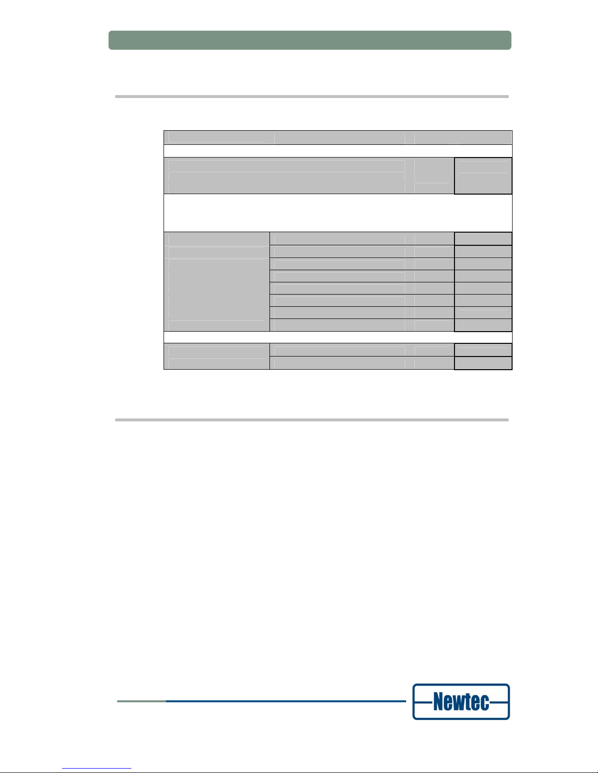
Options
AZ710 Upconverter
Default Configuration
Ordering n°
IF 70MHz or 140MHz to L-band Upconverter, SNMP
AZ710
Upconverter output: L-band (950 - 1750MHz)
10MHz reference In/Out 1ppm
Configuration Options
Category
Max. 1
option per
category
Output interface
L-band (950 - 1750 MHz)
Default
L-band + 10MHz for BUC
FA-02
L-band + 10MHz + 24Vdc for BUC
FA-03
L+C-band (5,85 - 6,65 GHz)
FA-04
L+Ku-band ( 12,75 - 13,25 GHz )
FA-05
L+Ku-band ( 13,75 - 14,50 GHz )
FA-06
L+DBS-band (17,30-18,10 GHz)
FA-07
L+DBS-band (17,60-18,40 GHz)
FA-08
10MHz reference In/Out Internal reference : 1ppm
Default
Internal reference : 0,01 ppm
GR-02
Feedback
Newtec encourages your comments concerning this document. We are committed
to providing documentation that meets your needs.
Please send any comments by contacting us at
documentation@newtec.eu.
Please include document and any comment, error found or suggestion for
improvement you have regarding this document.

Table of Contents
User Manual forAZ710 Up Converter
version 1.2
x
SHAPING THE FUTURE OF SATELLITE COMMUNICATIONS
TABLE OF CONTENTS
Compliancy Statements..........................................................................................ii
Safety Regulations .................................................................................................iv
About this Manual..................................................................................................vii
Table of Contents ....................................................................................................x
1 Introduction ....................................................................................................1
1.1 Short Description .............................................................................................1
1.2 Chapter Overview ............................................................................................1
2 Installation ......................................................................................................2
2.1 Rack Mounting .................................................................................................2
2.2 AC Power Supply .............................................................................................2
3 Physical Description .....................................................................................3
3.1 Front Panel Description ...................................................................................3
3.1.1 Display.........................................................................................................3
3.1.2 Keypad ........................................................................................................3
3.1.3 LEDs............................................................................................................4
3.2 Back Panel Description....................................................................................4
3.2.1 Power supply unit, Monitor &Control and external 10.0 MHz input.............5
3.2.2 C-band.........................................................................................................7
3.2.3 Ku-band Up converter .................................................................................8
4 How to manage ..............................................................................................9
4.1 Graphical User Interface (GUI) ........................................................................9
4.1.1 How to Connect ...........................................................................................9
4.1.2 GUI Description ...........................................................................................9
4.2 Front Panel ....................................................................................................11
4.3 RMCP ............................................................................................................11
4.3.1 Remote Monitor and Control .....................................................................11
4.3.2 Connecting the Converter .........................................................................12
4.3.3 Serial Interface and Line Settings .............................................................12
4.3.4 RMCP over Ethernet .................................................................................13
4.3.5 Protocol .....................................................................................................13
4.3.6 Message format.........................................................................................14

Table of Contents
User Manual forAZ710 Up Converter
version 1.2
xi
SHAPING THE FUTURE OF SATELLITE COMMUNICATIONS
4.4 SNMP.............................................................................................................14
5 Block Diagram..............................................................................................15
Appendix A: Technical Specifications ................................................................16
Appendix B: Abbreviations...................................................................................17

Introduction
User Manual forAZ710 Up Converter
version 1.2
1
SHAPING THE FUTURE OF SATELLITE COMMUNICATIONS
1 INTRODUCTION
1.1 Short Description
The AZ710 is a high performance frequency up converter designed for a wide
range of broadcast, telco and IP satellite applications. The AZ710 offers advanced
and unique features such as a calibrated high linearity over the entire bandwidth
combined with a very high frequency stability. These features make the AZ710 the
perfect solution for a wide range of transmissions ranging from very small carriers
to full transponder applications.
In its default configuration, the AZ710 converts IF to L-band signals. The IF input
frequency, is switchable between 70MHz and 140MHz. The L-band output
frequency ranges from 950MHz up to 1750MHz in steps of 48Hz. Optionally, the
AZ710 can be delivered with a C, Ku or DBS band with an L-band monitoring
output.
The high output frequency stability is provided by an internal 10 MHz reference
clock. For applications requiring very high frequency stability such as very low data
rate carriers, an optional reference clock of 0,01ppm can be ordered separately.
A DC power supply and a reference frequency on the L-band output are also
available as options, providing a compact and cost effective solution when the
AZ710 is used in combination with an outdoor RF up converter and/or amplifier.
The AZ710 is easy to operate and monitor. All control and monitoring parameters
are available locally on the front panel and remotely through a web interface. It is
also possible to control or monitor the AZ710 via RMCP or SNMP.
1.2 Chapter Overview
• Chapter 2 describes the physical installation parameters.
• Chapter 3 describes the physical interfaces and the front and back panel
connections of the device.
• Chapter 4 describes how to manage the AZ710 Up Converter.
• Chapter 5 gives a block diagram of the AZ710 Up Converter.
• Appendix A gives an overview of the technical specifications.
• Appendix B gives an explanation of the used abbreviations.

Installation
User Manual forAZ710 Up Converter
version 1.2
2
SHAPING THE FUTURE OF SATELLITE COMMUNICATIONS
2 INSTALLATION
2.1 Rack Mounting
The equipment is designed to operate in a 19-inch rack system conforming to IEC
60297.
When you mount the AZ710 Up Converter in a standard 19-inch equipment rack,
make sure to sustain it with L-profiles. If you mount the device with four front panel
screws only, you will damage the device and risk injuring yourself.
Operating the equipment in transportable installations is only permitted for
vehicles, ships or aircraft with the means for environmental conditioning. Operating
the equipment in transportable installations without these means may invalidate the
safety compliance.
When you mount the equipment in the rack, make sure that you do not
compromise the air flow that is needed to safely operate the equipment.
2.2 AC Power Supply
When switching the transmission equipment on, be careful not to
disturb the network.
This equipment is provided with a protective earthing incorporated in the power
cord. Only insert the mains plug in a socket outlet provided with a protective earth
contact (TN type power supply). Any interruption of the protective conductor, inside
or outside the equipment, is likely to make the equipment dangerous. Intentional
interruption is prohibited.
Install the equipment and connect it to the mains power supply system in
compliance with local or national wiring installation standards. Install the AZ710 Up
Converter so that its mains supply socket outlet is easily accessible or that there is
another suitable means to disconnect from the mains supply.
The power supply is set to operate from 100 to 240Vac to 47-63Hz.
Physical Description
User Manual forAZ710 Up Converter
version 1.2
3
SHAPING THE FUTURE OF SATELLITE COMMUNICATIONS
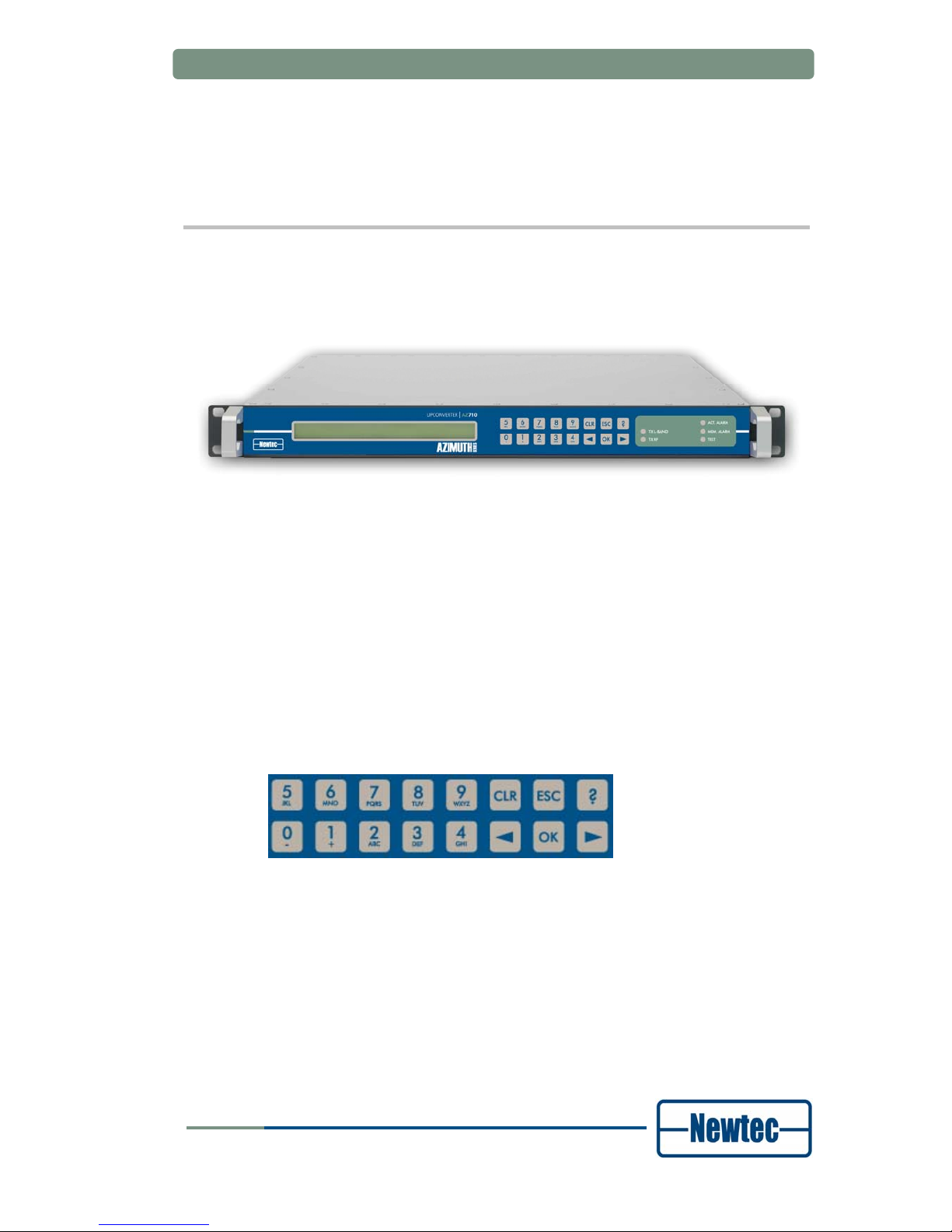
3 PHYSICAL DESCRIPTION
3.1 Front Panel Description
Figure 1 – AZ710 Up Converter front panel
3.1.1 Display
The display consists of a 2 x 40 characters LCD screen. The top row indicates the
path in the menu structure while the bottom row displays the selected item. If the
value is not indicated, press OK to open the sub menu.
3.1.2 Keypad
Figure 2 - SDH Keypad panel
With the 16 front panel keys you can navigate through the menus and change
parameters.
Press “?” to open a pop-up help screen with more information on the selected item.
To exit this screen, press ESC.
Use the “←” and “→” keys to highlight a menu item. Press OK (enter) to go one
level deeper in the menu tree. Once arrived at the desired level, press OK again to
select the desired item. Press ESC to move back up in the menu tree.
Press CLR (clear) to empty the numerical input fields (backspace).

Physical Description
User Manual forAZ710 Up Converter
version 1.2
4
SHAPING THE FUTURE OF SATELLITE COMMUNICATIONS
Press the digit keys 0 up to 9 to enter numerical values. When there is a need for
hexadecimal characters, press 0 – 9 to represent values zero to nine and A
through F to represent values ten to fifteen. To enter characters, press 0 – 9
multiple times until the desired character appears. Characters will appear first,
numbers last.
3.1.3 LEDs
There are six LEDs on the front panel.
Figure 3 -SDH Converter LEDs
Data In: green At least 1 data input is active and valid
Data Process: green The data are processed prior to transmission
Tx on: green The transmit is on
Act. Alm: red The actual alarm(s) is/are present
Mem. Alm: red The memorised alarm(s) is/are present
Test: orange On when the device is in test mode
3.2 Back Panel Description
The figure below shows the possible connections on the Up Converter. Keep in
mind that the back panel connections available on your device depend on your
specific hardware configuration. Therefore, they may differ from the ones shown in
the figure below. The back panel consists of several hardware modules. In the
following paragraphs these modules are described in more detail.
Figure 4 – Back Panel of the AZ710

Physical Description
User Manual forAZ710 Up Converter
version 1.2
5
SHAPING THE FUTURE OF SATELLITE COMMUNICATIONS
3.2.1 Power supply unit, Monitor &Control and external 10.0 MHz input
ALARM
10/100Base- T
Ref. In
M& C RS232/485
100-26 0 VAC LIN E
Figure 5 - PSU, Monitor and Control and external 10 MHz reference
3.2.1.1 Power socket
This equipment has a protective earthing ground incorporated in the power cord.
Do not insert the mains plug in a socket outlet without a protective
earth contact. Any interruption of the protective conductor, inside
or outside the instrument, is likely to make the instrument
dangerous.
3.2.1.2 Serial Monitoring and Control via RS485/RS232
The AZ710 Up Converter contains the hardware for the RS485 and RS232
interface. Use the front panel or Ethernet to select the serial interface type. You
cannot do this through the serial port itself.
Figure 6 - Serial Monitoring and Control connector
RS485 serial interface:
Pin Name Function
1 GND Shield ground
2 Not connected
3 Tx-A Send Data A (input)
4 Rx-A Receive Data A (output)
5 GND Signal ground
MON & CTRL
5
9
1
6

Physical Description
User Manual forAZ710 Up Converter
version 1.2
6
SHAPING THE FUTURE OF SATELLITE COMMUNICATIONS
Pin Name Function
6 Rx-B Receive Data B (output)
7 Not connected
8 Not connected
9 Tx-B Send Data B (input)
Table 1 - RS485 pin configuration
RS232 serial interface:
Pin Name Function
1 GND Shield ground
2 Rx-D Receive Data (input)
3 Tx-D Transmit Data (output)
4 DTR Data Terminal Ready (output)
5 GND Signal ground
6 Not connected
7 RTS Request to send (output)
8 CTS Clear to send (input)
9 Not connected
Table 2 - RS232 pin configuration
3.2.1.3 Contact closure alarm outputs
You can use the contact closure alarm contacts to drive external alarm indicators
(sirens, flashlights, etc.) or to connect to a redundancy switching system.
Figure 7 - Contact closure alarm outputs
1 ok
3 alarm
2 Common
general alarm
1 ok
3 alarm
2 Common
general alarm
Figure 8 - Contact closure alarm connections
Pin 2 and 4 are either floating or tied to chassis earthing.
Physical Description
User Manual forAZ710 Up Converter
version 1.2
7
SHAPING THE FUTURE OF SATELLITE COMMUNICATIONS
3.2.1.4 10.0 MHz Reference Input
This input is used when you need a reference with enhanced stability or when you
need several Converters to be synchronised to the same clock source. The level
should be 0 dBm nominally. This input is only valid if the device is equipped with an
NTC/3462 10 MHz reference frequency module.
3.2.1.5 Ethernet Connection
A standard RJ-45 connector provides connection to an Ethernet hub in a LAN
(10/100BaseT). You can use the front panel to set the IP address and to mask
while in normal mode.
You can use the Ethernet interface to send RMCP commands to the AZ710 Up
Converter. Send the commands as data in a TCP/IP stream. Use socket number
5933. Make sure the RMCP protocol is exactly the same as for the serial interface,
with one small exception: the RMCP address of the device (that is present in an
RMCP command) is ignored by the receiving device.
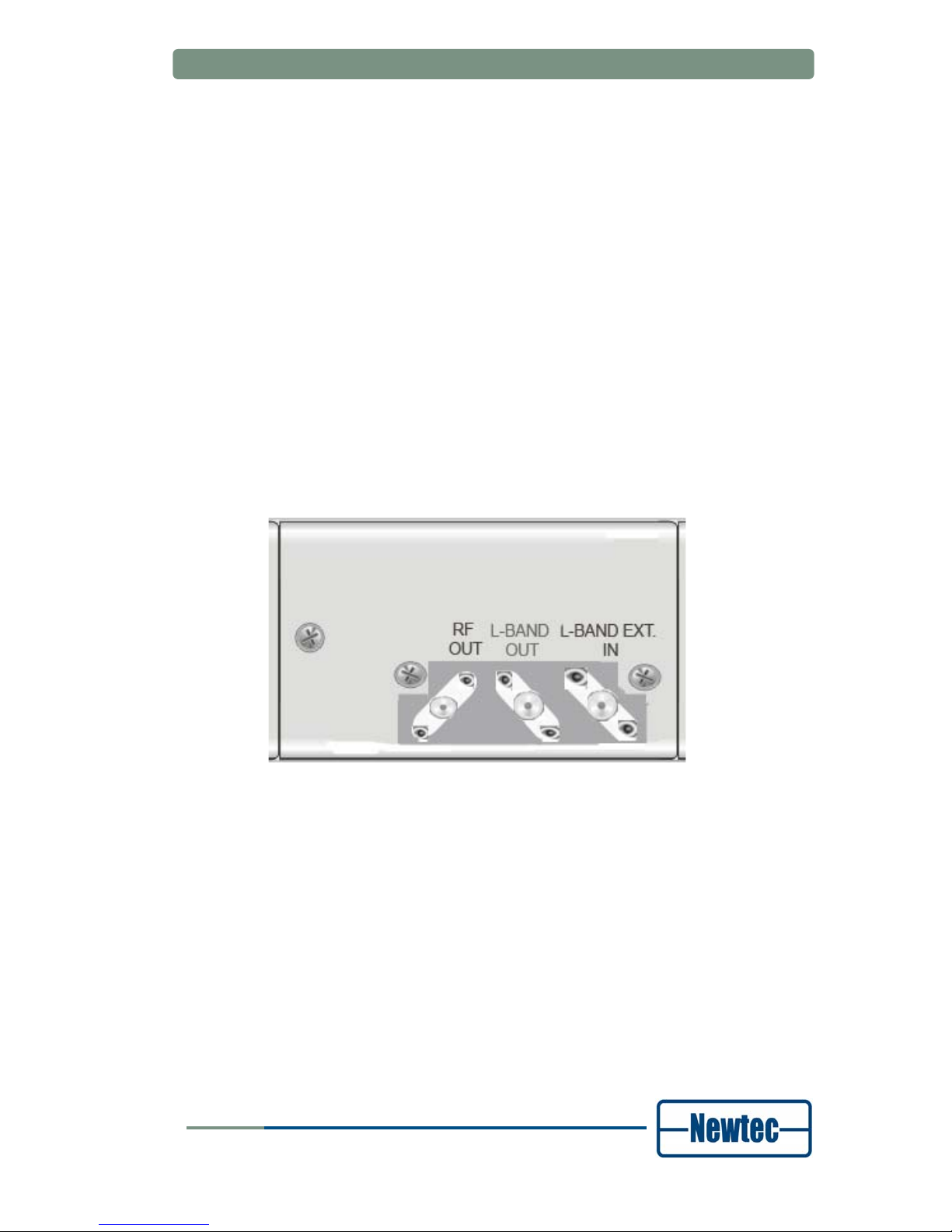
3.2.2 C-band
1. Up converted signal C-band
2. L-band signal ouput
3. External L-band signal (optional)
1
2
3

Physical Description
User Manual forAZ710 Up Converter
version 1.2
8
SHAPING THE FUTURE OF SATELLITE COMMUNICATIONS
3.2.3 Ku-band Up converter
1. Ku output (RF output) : 13750 - 14500 MHz
2. External L-band signal (optional)
3. L-band signal output
1
2
3

How to manage
User Manual forAZ710 Up Converter
version 1.2
9
SHAPING THE FUTURE OF SATELLITE COMMUNICATIONS
4 HOW TO MANAGE
4.1 Graphical User Interface (GUI)
4.1.1 How to Connect
4.1.1.1 Cabling
Use a crossed network cable to connect the Ethernet port of the AZ710 Up
Converter to the Ethernet port of a computer.
4.1.1.2 Software
The platform is equipped with a powerful and easy-to-use graphical user interface
(GUI) that allows you to remotely monitor and control your equipment through a
web browser.
To use the web interface, adapt the TCP/IP properties of the computer so you can
manually set an IP address that is within the range of the device IP address. For
example: take IP address 10.0.0.2 on the computer and 10.0.0.1 on the device.
Make sure that no pop-up blockers or firewall are active.
To adapt the TCP/IP properties on a typical Windows computer:
¾ Choose Start > Connect To > Show all connections.
¾ Right-click Local Area Connection.
¾ Click Properties.
¾ Scroll down and click Internet Protocol (TCP/IP).
¾ Click Properties.
¾ Choose Use the following IP address.
¾ Enter the following data:
- IP address, for example: 10.0.0.2.
- Subnet mask, for example: 255.255.255.0
4.1.2 GUI Description
Use a web browser (Internet explorer 5.5 or later, Mozilla, etc.) to open the web
interface of the AZ710 Up Converter. Type the following address in the address
bar:
http://ip_address_device. You can find the IP address device in the following
menu on the front panel of the device: AZ710/Unit/Setup/Ethernet settings.

How to manage
User Manual forAZ710 Up Converter
version 1.2
10
SHAPING THE FUTURE OF SATELLITE COMMUNICATIONS
By default, the IP address of all Newtec devices is 10.0.0.1.
AZ710/Unit/Setup/Ethernet
Device IP address: 10.0.0.1
In this mode, click AZ710 on the left side of the screen to get an overview of all the
parameters in the device.
To change the parameters of the device, click Log In to log into the device.
Log in with the user name and password that is defined in the web interface menu:
AZ710 >> Unit >> Setup >> Web interface menu
By default the login credentials <root> respectively.
Once logged in, there are three levels:
• Read-only: in this mode you can only see (read) the
parameters corresponding to the operator mode. You cannot
change them.
• Operator: this mode corresponds with the device Normal
mode. It enables the default set of parameters that are most
frequently used.
• Administrator: this mode corresponds with the device Expert
mode and gives you access to an additional set of more
advanced parameters.
You can now remotely view and change all the parameters of the device through
the GUI.

How to manage
User Manual forAZ710 Up Converter
version 1.2
11
SHAPING THE FUTURE OF SATELLITE COMMUNICATIONS
The GUI displays seven main menus:
• Home: this menu allows you to remotely monitor and control all
the parameters of the device through the web-interface. You
can also change all the parameters that can be changed
through the keypad here.
• Logging: this menu gives an overview of the most recent
events.
• Alarmlog: in this menu you can view the most recent alarms.
• Diagnostics report: this menu generates a diagnostics report
with an overview of the status of the different parameters of the
device. This is very useful to have near you when you contact
support for technical questions.
• Manual: the complete manual with RMCP commands of the
corresponding device is stored here in HTML format.
• Log In resp Log out: this menu is used to log in to or out of
the device.
• About: this menu shows the version number of the GUI you
are using.
In the yellow bar on the screen you can see where the parameters are located in
the parameter tree of the device.
Go to the following menu to find the parameters Serial baudrate and Device
RMCP address:
AZ710 >> Unit >> Setup >> Serial port settings
This is the same tree you have to follow in the directory tree when using the front
panel to change these settings.
4.2 Front Panel
The first line of the display contains your current location in the menu tree of the
device. The second line contains the parameter name and its value.
AZ710/Unit/Control
Device sleep mode: operational
4.3 RMCP
4.3.1 Remote Monitor and Control
Remote monitor and control (RMCP) is possible via the serial interface
(RS232/485) or through RMCP over Ethernet. The commands are described in the
device Reference Manual.

How to manage
User Manual forAZ710 Up Converter
version 1.2
12
SHAPING THE FUTURE OF SATELLITE COMMUNICATIONS
Go to www.newtec.eu and choose Support > Download Area >
RMCP Loader to download and install the RMCP Loader for free.
Detailed RMCP information is available in the RMCP reference
manual. Please contact our Technical Support at
support@newtec.eu for the relevant documentation and guidance.
4.3.2 Connecting the Converter
The device is set to RS485 by factory default. When you prefer RS232, choose:
AZ710 >> Unit >> Setup >> Serial port settings
Default serial port settings:
AZ710/Unit/Setup/Serial port settings:
• Serial interface type RS485
• Device RMCP address 100
• Serial baud rate 115200
Alternatively, use an RS232 to RS485 converter to connect the Monitor and
Control port to a serial communication port of a PC. Pin out on the converter can
differ depending on the brand and type of the converter.
When using RS232, use a null-modem cable with the following layout:
PC Device Signal
9 Pin D-types 9 Pin D-types
2 3 TxD
3 2 RxD
5 5 GND
Table 3 - RS232 cable pin layout
4.3.3 Serial Interface and Line Settings
The main line settings for this serial interface are:
• Asynchronous data transfer
• 1 start bit (logic "0")
• 7 data bits (LSB first on line)
• Even parity
• 1 stop bit (logic "1")
• 4800, 9600, 19200, 38400, 57600 or 115200 baud
To set the serial baudrate, choose:

How to manage
User Manual forAZ710 Up Converter
version 1.2
13
SHAPING THE FUTURE OF SATELLITE COMMUNICATIONS
AZ710 > Unit > Setup > Serial port settings.
There is no flow control on the serial interface. Apart from correctly formatted
messages, the only significant character here is the SYNC-character (value 16
hex). The AZ710 Up Converter sends this character to indicate that it is busy
executing the command and preparing the response. This prevents other devices
from taking control of the bus if the response cannot be given immediately.
4.3.4 RMCP over Ethernet
You can send RMCP commands to the AZ710 Up Converter using the Ethernet
interface. The commands are sent as data in a TCP/IP stream. The used socket
number is 5933.The RMCP protocol is exactly the same as for the serial interface,
with one small exception: the receiving device ignores the RMCP address of the
device that is present in an RMCP command.
To enable the device to communicate over Ethernet, you need to configure the
Ethernet interface. See:
AZ710 >> Unit >> Setup >> Ethernet settings
4.3.5 Protocol
The control unit sends a “request” message to a device identified by its unique
address. The addressed device interprets the message, performs the requested
action and sends a “response” message back.
The receiving device rejects all messages with transmission errors without any
further action. Transmission errors are:
• No stop bit
• Parity error
• LRC-error
• Message receive buffer overflow
The addressed device responds to all correct formatted messages – except for
some special system messages – with an acknowledge message. Only in a few
restricted cases does the device not respond to a request from the control unit.
This is, for example, the case when a general device reset is requested.
Correctly received messages which the device cannot handle are refused via a noacknowledge “error” message. This message contains the reason why the
message is rejected.
A device never sends messages on its own initiative. It only responds to a request
from the control unit. The total transmit time of a complete message may not
exceed 250 ms. If the message is not completed within this time, it is discarded.

How to manage
User Manual forAZ710 Up Converter
version 1.2
14
SHAPING THE FUTURE OF SATELLITE COMMUNICATIONS
4.3.6 Message format
The general syntax for all messages is:
• Start byte
• Address byte
• Message header
• Message data
• End of text byte
• Checksum byte
4.4 SNMP
The Newtec MIB allows full monitor and control over the complete device using any
SNMP browser (HP-OpenView, NetworkView). Newtec supports the basic standard
MIB (monitor and control of IP interface, versions of the software …) and above
that we have a full proprietary MIB, which contains all the OIDs needed to control
the device.
We support traps. These form a mechanism to trigger the NMS when a change in
the device has occurred. After receiving the trap the NMS still has to poll the device
to find out the details of the change.
The SNMP details can be found in the AZ710 Reference Manual.
Block Diagram
User Manual forAZ710 Up Converter
version 1.2
15
SHAPING THE FUTURE OF SATELLITE COMMUNICATIONS
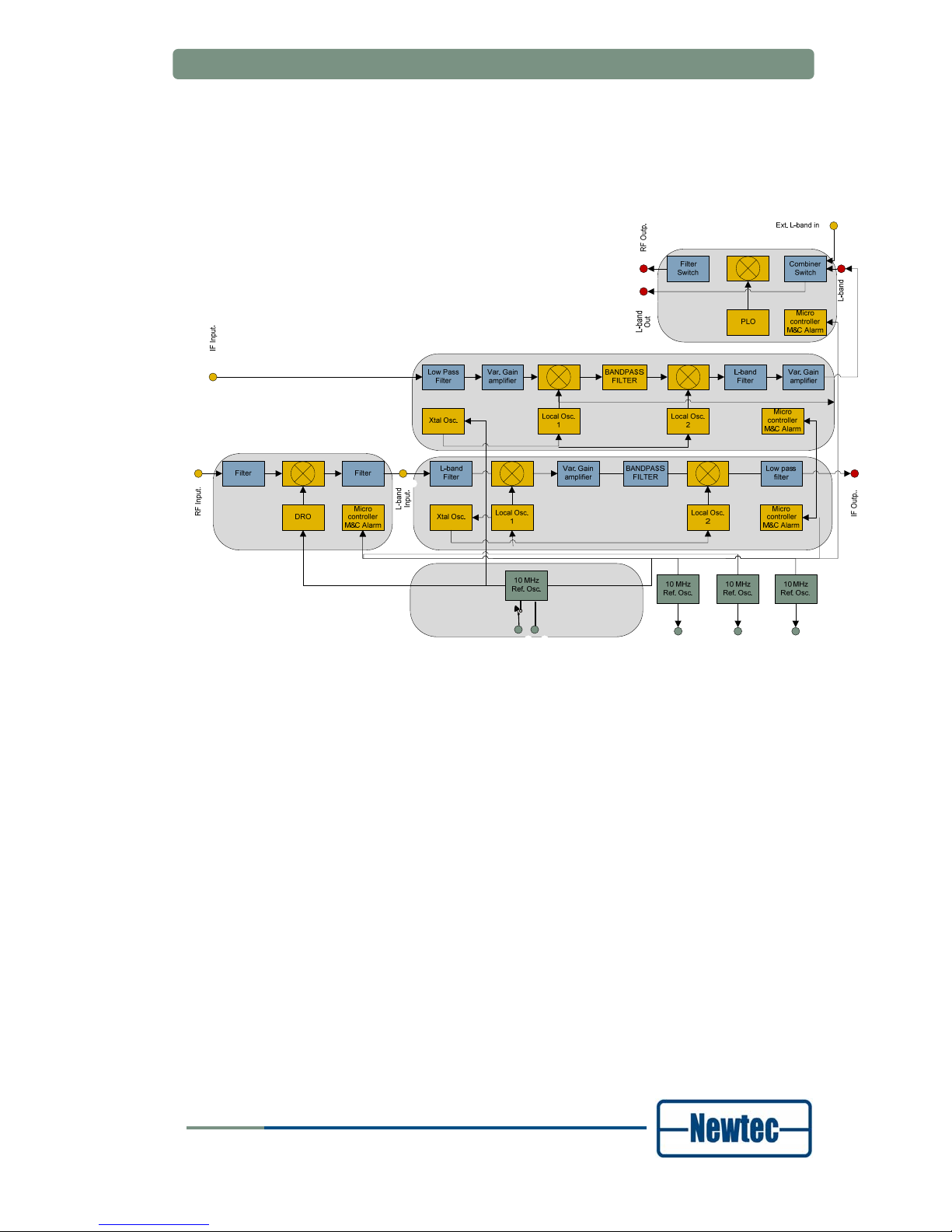
5 BLOCK DIAGRAM
Figure 9 – AZ710 Up Converter Block Diagram

Appendix A: Technical Specifications
User Manual for AZ710 Up Converter
version 1.2
16
SHAPING THE FUTURE OF SATELLITE COMMUNICATIONS
APPENDIX A: TECHNICAL SPECIFICATIONS

Appendix B: Abbreviations
User Manual for AZ710 Up Converter
version 1.2
17
SHAPING THE FUTURE OF SATELLITE COMMUNICATIONS
APPENDIX B: ABBREVIATIONS
Abbreviation Description
BUC Block Up Converter
CAT Conditional Access Table
C/N Carrier to Noise
CCM Constant Coding and Modulation
CW Control Word
DC Direct Current
DES Data Encryption Standard
DSM&CC Digital Storage Media Command and Control
DVB-S Digital Video Broadcasting - Satellite transmission standard
DVB-S2 Digital Video Broadcasting - Satellite transmission 2nd generation standard
DVB-DSNG Digital Video Broadcasting – Digital Satellite News Gathering transmission
standard
EMC Entitlement Control Message
EMM Entitlement Management Message
ETH Ethernet
ESW Encrypted Session Word
FEC Forward Error Correction
FIPS Floating-Point Instructions per Second
FPGA Field-programmable Gate Array
GND Ground
GPS Global Positioning System
GUI Graphical User Interface
HPA High Power Amplifier
Hz Herz
ID Identification
IDb buried Identifier
IDi injected Identifier
IFL Inter Facility Link
IP Internet Protocol
IPE IP Encapsulation
IRD Integrated Receiver Decoder
ISI Input Stream Identifier
LCD Liquid Crystal Display
LED Light Emitting Diode
LLC Logical Link Control
LNB Low Noise Block Converter
LO Local Oscillator
M&C Monitoring and Control
MIB Management Information Base
MPEG Motion Picture Experts Group
MUX Multiplex

Appendix B: Abbreviations
User Manual for AZ710 Up Converter
version 1.2
18
SHAPING THE FUTURE OF SATELLITE COMMUNICATIONS
Abbreviation Description
ODU Outdoor Unit
PAT Program Association Table
PCR Program Clock Reference
PID Packet Identification Number
PMT Programme Map Table
PSK Phase Shift Keying
QAM Quadrature Amplitude Modulation
QPSK Quadrature Phase Shift Keying
RAS Remote Access Server
RF Radio Frequency
RMCP Remote Monitoring and Control Protocol
RS Reed Solomon
RTP Real-time Transmission Protocol
SFN Single Frequency Network
SMA Surface-Mounted Assembly (connector)
SNAP Sub Network Access Protocol
SNMP Simple Network Management Protocol
SPI Serial-to-Parallel Interface
STB Set Top Box
STS Synchronisation Time Stamp
TCP/IP Transmission Control Protocol/ Internet Protocol
TPS Transmission Parameter Signalling
TS Transport Stream
UDP User Datagram Protocol
USS Universal Switching System
VCM Variable Coding Modulation
 Loading...