


version 1.0
AZ430 WAN Satellite Modem
for
User Manual
SHAPING THE FUTURE OF SATELLITE COMMUNICATIONS

User Manual for AZ430 WAN Satellite Modem
© 2009 Newtec cy.
The material contained in this document is confidential and intended for use only
by parties authorised by Newtec.
All Rights Reserved. No part of this document may be photocopied, reproduced,
stored in a retrieval system, or transmitted, in any form or by any means whether,
electronic, mechanical, or otherwise without the prior written permission of
Newtec cy.
Newtec cy
Laarstraat 5
9100 Sint-Niklaas, Belgium
General: +32 (0)3 780 65 00
www.newtec.eu
Fax +32 (0)3 780 65 49
General:
general@newtec.eu
version 1.0
i
SHAPING THE FUTURE OF SATELLITE COMMUNICATIONS

Compliancy Statements
User Manual for AZ430 WAN Satellite Modem
COMPLIANCY STATEMENTS
TO WHOM IT MAY CONCERN
EC DECLARATION OF CONFORMITY
We,
NEWTEC CY nv.
Declare that the following product:
Product number:
with type identifiers : NTC/2210 (IF) and NTC/2215 (L-Band)
to which this declaration relates is in conformity with the essential requirements of
European Union Directive 1999/5/EC Radio and Telecommunication Terminal
Equipment Directive Essential Requirement 3.1(a), 3.1 (b), 3.2.
Done at St-Niklaas, on 28 October, 2009
Serge Van Herck,
CEO
version 1.0
ii
SHAPING THE FUTURE OF SATELLITE COMMUNICATIONS

Compliancy Statements
User Manual for AZ430 WAN Satellite Modem
TO WHOM IT MAY CONCERN
Restriction of Hazardous Substances Directive (RoHS)
(Directive 2002/95/EC)
The undersigned hereby confirms the following statement:
We hereby declare that all Newtec equipment, delivered after July 1, 2006 and
used in network infrastructure equipment for switching, signalling or transmission
will be compliant to the RoHS Directive 2002/95/EC. We hereby take into account
the exemption for the use of lead in solders as specified in the annex of the
Directive. This exemption is further clarified in a study ordered by the European
Commission “Technical adaptation under Directive 2002/95/EC (RoHS) –
Investigation of exemptions (ERA Report 2004-0603, ERA Project 043121279)”
Newtec is making serious efforts to completely ban lead in solders throughout its
entire product range and in the shortest possible timeframe. If you have
applications where you intend to use Newtec equipment in an infrastructure other
than network infrastructure for switching, signalling or transmission, please do not
hesitate to contact us. As in time more and more Newtec equipment will be totally
leadless, we will inform you on the status of the equipment you intend to use at that
time.
Done at St-Niklaas, on 28 October, 2009
Serge Van Herck,
CEO
version 1.0
iii
SHAPING THE FUTURE OF SATELLITE COMMUNICATIONS
Safety Regulations
User Manual for AZ430 WAN Satellite Modem
SAFETY REGULATIONS
Please read this chapter before you install and use this equipment.
To ensure your safety, the equipment has been designed to comply with the
following safety standard:
IEC 60950 Safety of Information Technology Equipment
Before you start to install and operate the modem, please make sure you observe
the following points:
• The equipment described in this manual is designed to be used by properly
trained personnel only. Only qualified personnel who are aware of hazards
involved may adjust, maintain and repair the equipment.
The AZ430 Telco Satellite Modem has no operator serviceable
parts inside. Refer servicing to qualified personnel. To prevent
electrical shock, do not remove covers.
• To use the equipment correctly and safely, it is essential that both operating and
servicing personnel follow generally accepted safety procedures in addition to
the safety precautions specified in this manual. Warning and caution statements
and/or symbols are marked on the equipment when necessary. Whenever it is
likely that safety protection is impaired, immediately switch off the equipment
and secure it against unintended operation. Inform the appropriate servicing
authority about the problem. For example, safety is likely to be impaired if the
equipment fails to perform the intended measurements or shows visible
damage.
Caution1:
FOR CONTINUED PROTECTION AGAINST FIRE, REPLACE
LINE FUSES ONLY WITH SAME TYPE AND RATING (5 X 20mm
T3.15 A/250v TYPE T or slow-blow).
Caution 2:
THERE IS RISK OF EXPLOSION IF THE BATTERY IS
REPLACED WITH AN INCORRECT TYPE. DISPOSE OF USED
BATTERIES ACCORDING TO THE INSTRUCTIONS.
version 1.0
iv
SHAPING THE FUTURE OF SATELLITE COMMUNICATIONS

Safety Regulations
User Manual for AZ430 WAN Satellite Modem
Additional safety requirements for Finland, Norway and
Sweden
Telecommunication connections and cable distribution system.
Special conditions apply to the use of this equipment in Finland,
Sweden and Norway due to different earthing arrangements in
these countries. Therefore it is essential that the installation is
done by authorized personnel and according to the national
requirements only.
This equipment is specified for use in a restricted access location
only, where equipotential bonding has been applied and which
has provision for a permanently connected protective earthing
conductor.
A protective earthing conductor must be installed by a Service
Person.
EMC Information
Relevant EMC information (to FCC rules)
This equipment has been tested and was found to comply with the limits for a class
A digital device, pursuant to part 15 of the FCC Rules. These limits are designed to
provide reasonable protection against harmful interference when the equipment is
operated in a commercial environment. This equipment generates, uses and
radiates radio frequency energy. If not installed and used in accordance with the
instruction manual, it may cause harmful interference to radio communications.
Do not operate this equipment in a residential area, as it is likely to cause harmful
interference. When this is the case, you will be required to correct the interference
at your own expense.
version 1.0
v
SHAPING THE FUTURE OF SATELLITE COMMUNICATIONS

Safety Regulations
User Manual for AZ430 WAN Satellite Modem
Environmental
Operating the equipment in an environment other than that stated in the
specifications also invalidates the safety compliance.
Do not use the equipment in an environment in which the unit is exposed to:
• Unpressurised altitudes higher than 2000 metres.
• Extreme temperatures outside the stated operating range.
• Operating temperature range 0 to + 40 °C (*).
• Excessive dust.
• Moist or humid atmosphere above 95% RH.
• Excessive vibration.
• Flammable gases.
• Corrosive or explosive atmospheres.
• Direct sunlight.
(*): DC power supply - Operating temperature range 0 to + 30 °C.
Use a slightly damp cloth to clean the casing of the equipment. Do not use any
cleaning liquids containing alcohol, methylated spirit or ammonia etc.
Warranty
Newtec guarantees the durability and satisfactory electrical and mechanical
performance of the equipment to a maximum period of one (1) year from the date
of delivery, unless otherwise agreed to, in writing. The warranty only applies to
manufacturing defects and only when the equipment is handled, installed,
maintained and adjusted in line with the instructions provided by Newtec and in line
with good practice. The warranty does not apply to items normally consumed in
operation or which have a normal life time inherently shorter than the warranty
stated above, such as, without limitation, fuses or lamps. Any defect due to normal
wear and tear or caused by transportation Force Majeure events or attributable to
the Customer’s improper use, neglect, storage, operation handling or maintenance
of the goods or any part thereof, are excluded from the warranty. During the
warranty period, Newtec shall, at its sole discretion, replace or repair the defective
sub-parts or units at the source factory. All transportation costs shall be borne and
prepaid by the Customer.
version 1.0
vi
SHAPING THE FUTURE OF SATELLITE COMMUNICATIONS
About this Manual
User Manual for AZ430 WAN Satellite Modem
ABOUT THIS MANUAL
This document provides a quick overview on how to easily set up the modem for
the most common use cases.
This document is intended to help you:
• Find your way around the GUI.
• Understand the different possibilities of the with a Telco interface board.
Cautions and Symbols
The following symbols appear in this manual:
A caution message indicates a hazardous situation that, if not
avoided, may result in minor or moderate injury. It may also refer
to a procedure or practice that, if not correctly followed, could
result in equipment damage or destruction.
A hint message indicates information for the proper operation of
your equipment, including helpful hints, shortcuts or important
reminders.
A reference message is used to direct to an internal reference
within the document, a related document or a web-link.
version 1.0
vii
SHAPING THE FUTURE OF SATELLITE COMMUNICATIONS

About this Manual
User Manual for AZ430 WAN Satellite Modem
Version History and Applicability
Document
version
Date Subject Author Comment
Version 1.0 October 23th 2009 AZ430 EDE/GWI Initial Release
Related Documentation
• The Reference Manual describes all the parameters available in the
Modem.
• The Equalink
TM
User Manual details the linear and non-linear pre-distortion
capabilities.
• The RMCP manual explains how Newtec devices can be remotely
monitored and controlled via the serial port or via Ethernet. A copy of a
separate general RMCP manual can be obtained via
TechSupport@newtec.eu.
Applicability
Product range
Software ID
M&C ntc6293
Software versions
Release 6
version 1.0
viii
SHAPING THE FUTURE OF SATELLITE COMMUNICATIONS

About this Manual
User Manual for AZ430 WAN Satellite Modem
Options
AZ 430 WANSatellite Modem Order n°
Default Configuration Order n°
DVB modem with HSSI interfaces, L-band (950-2150 MHz) input, SNMP
HSSI interface rate: up to 52 Mbit/s
Output interface mod: L-band (950-1750 MHz)
Modulation: Q/8PSK
AZ430
Configuration options Max. 1 option per category
max. 52 Mbit/s Default HSSI interface rate
max. 110 Mbit/s (extended) AG-08
L-band (950-2150 MHz) Default
L-band + 10MHz AJ-02
Input Interface Mod
IF + L-band (only with IF Mod output) AJ-03
L-band (950-1750 MHz) Default
IF (50-180 MHz) AA-02
L-band + 10MHz for BUC AA-03
Output Interface Mod
L-band + 10MHz + 24Vdc for BUC AA-04
DVB-S/S2 Q/8PSK * Default
DVB-S/S2 Q/8PSK, 16QAM, 16APSK * AB-12
Modulation
DVB-S/S2 Q/8PSK, 16QAM, 16/32APSK * AB-16
Additional options Max. 1 option per category
High stability GR-01 10MHz reference
In/Out
Very high stability GR-02
Predistortion Equalink * AC-01
Customization options Max. 1 option per category
Power Supply -48V DC PS-02
Services Max. 1 option per category
Warranty 12 months Default
18 months GW_02
24 months GW_03
36 months GW_04
Helpdesk Default Assistance
Remote assistance GA-02
(*) Upgradeable via license key
version 1.0
ix
SHAPING THE FUTURE OF SATELLITE COMMUNICATIONS

About this Manual
User Manual for AZ430 WAN Satellite Modem
Feedback
Newtec encourages your comments concerning this document. We are committed
to providing documentation that meets your needs
.
Please send any comments by contacting us at documentation@newtec.eu.
Please include document and any comment, error found or suggestion for
improvement you have regarding this document.
version 1.0
x
SHAPING THE FUTURE OF SATELLITE COMMUNICATIONS

Table of Contents
User Manual for AZ430 WAN Satellite Modem
TABLE OF CONTENTS
Table of Contents ...................................................................................................xi
1 Introduction....................................................................................................1
1.1 Short Description .............................................................................................1
1.2 Contents of the Document...............................................................................2
2 Installation......................................................................................................3
2.1 Rack Mounting.................................................................................................3
2.2 Power Supply...................................................................................................3
2.2.1 AC Power Supply ........................................................................................3
2.2.2 Cable Distribution System ...........................................................................3
2.2.3 Technical Earthing.......................................................................................4
3 Physical Description .....................................................................................5
3.1 Front Panel Description ...................................................................................5
3.1.1 Display .........................................................................................................5
3.1.2 Keypad ........................................................................................................5
3.1.3 LEDs ............................................................................................................6
3.2 Back Panel Description....................................................................................7
3.2.1 PSU, M&C Interface and External 10.0 MHz Reference Input....................7
3.2.2 Telco Back panel Interface ........................................................................10
3.2.3 L-Band Modulator Back panel Interface ....................................................11
3.2.4 Demodulator Back panel Interface ............................................................11
4 How to Manage.............................................................................................12
4.1 Graphical User Interface (GUI)......................................................................12
4.1.1 How to Connect .........................................................................................12
4.1.2 GUI Description .........................................................................................12
4.2 Front Panel ....................................................................................................15
4.3 RMCP ............................................................................................................16
4.3.1 Remote Monitor and Control .....................................................................16
4.3.2 Connecting the Modem .............................................................................16
4.3.3 Serial Interface and Line Settings .............................................................17
4.3.4 RMCP over Ethernet .................................................................................17
4.3.5 Protocol .....................................................................................................18
4.4 SNMP.............................................................................................................18
5 Block Diagram..............................................................................................19
version 1.0
xi
SHAPING THE FUTURE OF SATELLITE COMMUNICATIONS

Table of Contents
User Manual for AZ430 WAN Satellite Modem
6 Features........................................................................................................21
6.1 The Noise and Distortion Estimator (NoDE)..................................................21
6.1.1 Introduction ................................................................................................21
6.1.2 How does NoDE work ...............................................................................21
6.2 Equalink .........................................................................................................24
6.3 Demodulator Statistics...................................................................................25
6.3.1 FEC-rate and mod .....................................................................................25
6.3.2 Frame type ................................................................................................25
6.3.3 Pilots ..........................................................................................................25
6.3.4 BB frame count..........................................................................................25
6.3.5 Uncor frame count .....................................................................................25
6.3.6 Channel quality estimation ........................................................................26
6.3.7 C/D est.......................................................................................................26
6.3.8 C/D clipping ...............................................................................................26
6.3.9 Link margin est. .........................................................................................26
6.3.10 Link margin clipping...................................................................................26
Appendix A – Technical Specifications...............................................................27
Appendix B – User Defined Menu........................................................................32
Appendix C – List of Abbreviations.....................................................................33
version 1.0
xii
SHAPING THE FUTURE OF SATELLITE COMMUNICATIONS

Introduction
User Manual for AZ430 WAN Satellite Modem
1 INTRODUCTION
1.1 Short Description
The AZ430 is a state-of-the-art satellite modem designed for applications where
two parts of a Wide Area Network (WAN) are connected over satellite using routers
with HSSI interfaces.
The AZ430 interfaces directly with terrestrial routers through an HSSI interface with
bit rates up to 52 Mbit/s (standard HSSI) or 110 Mbit/s (extended HSSI).
This modem is fully compatible with DVB-S and DVB-S2 standards and provides
exceptional performance and bandwidth efficiency.
At the output of the modulator, the signal is available on an L-band interface. IF
band as well as HPA control functions are available as configuration options. When
activated, the unique linear and non- linear predistortion option Equalink™ provides
an additional link margin improvement of up to 2,5dB.
On the receive side, the AZ430 has a dual L-band input (950-2150 MHz). The
active input is selected by the user and can provide DC power and frequency band
selection signals compatible with most professional and commercial LNBs. An
adaptive equalizer compensates linear distortion of the transmission channel.
The integrated Noise & Distortion Estimator (NoDE) tool provides an accurate
reading of the satellite link margin even in presence of non-linear distortion and
allows the user to find the optimum input back-off setting very easily for 16APSK or
32APSK operation, whether or not non-linear predistortion is applied .
version 1.0
1
SHAPING THE FUTURE OF SATELLITE COMMUNICATIONS

Introduction
User Manual for AZ430 WAN Satellite Modem
1.2 Contents of the Document
• Chapter 2 describes the physical installation parameters.
• Chapter 3 describes the physical interfaces and the front and back panel
connections of the modem.
• Chapter 4 describes how to manage the modem.
• Chapter 5 describes the block diagram of the Modem.
• Chapter 6 describes the features of the modem.
• Appendix A contains the technical specification.
• Appendix B contains the user defined menu.
• Appendix C contains the list of abbreviations.
version 1.0
2
SHAPING THE FUTURE OF SATELLITE COMMUNICATIONS

Installation
User Manual for AZ430 WAN Satellite Modem
2 INSTALLATION
2.1 Rack Mounting
The equipment is designed to operate in a 19-inch rack system conform to IEC
60297. When mounted in a standard 19-inch equipment rack, make sure you
sustain it with L-profiles. Do not fix the modem with four front panel screws only,
since this will damage the modem and could result in self injury.
It is allowed to operate the equipment in transportable installations and vehicles
equipped with the means to provide a stable environment. Do not operate the
equipment on vehicles, ships or aircraft without the means of environmental
conditioning, as this may invalidate the safety compliance.
Mount the equipment in the rack in such a way that the amount of air flow required
to safely operate the equipment is not compromised.
2.2 Power Supply
2.2.1 AC Power Supply
This equipment is provided with a protective earthing incorporated in the power
cord. Be careful to insert the mains plug only in a socket outlet provided with a
protective earth contact (TN type power supply). Any interruption of the protective
conductor inside or outside the equipment is likely to make the equipment
dangerous. Intentional interruption is prohibited.
Install and connect the equipment to the mains power supply system in compliance
with local or national wiring installation standards. Position the equipment so that
the mains supply socket outlet for the equipment is near the equipment and can
easily be accessed or that there are other suitable means to disconnect from the
mains supply.
The power supply is set to operate from 100 to 240Vac to 47-63Hz.
2.2.2 Cable Distribution System
Install the equipment in accordance with the applicable provisions of NEC Article
810 for US and with CEC section 54 for Canada. Before connecting the coax to the
equipment, make sure that the equipment is properly earthed. The screen of the
used coax cable should be grounded according to the local regulations.
version 1.0
3
SHAPING THE FUTURE OF SATELLITE COMMUNICATIONS

Installation
User Manual for AZ430 WAN Satellite Modem
2.2.3 Technical Earthing
On the rear panel of the equipment a technical earthing is available (an unmarked
terminal on the right side of the equipment). It is provided to:
• Ensure that all equipment chassis fixed within a rack are at the same technical
earth potential. This is done by connecting a wire between the technical earth
terminal and a suitable point on the rack.
• Eliminate the migration of stray charges when connecting between equipment.
version 1.0
4
SHAPING THE FUTURE OF SATELLITE COMMUNICATIONS
Physical Description
User Manual for AZ430 WAN Satellite Modem
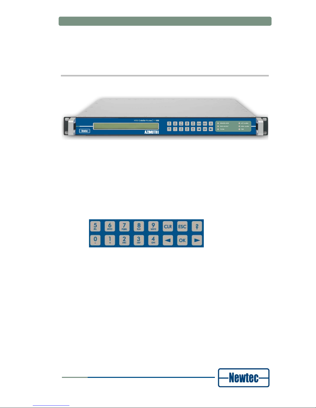
3 PHYSICAL DESCRIPTION
3.1 Front Panel Description
Figure 1 – AZ430 Telco Satellite Modem
3.1.1 Display
The display consists of a 2 x 40 characters LCD screen. The top row indicates the
path in the menu structure while the bottom row displays the selected item. If the
value is not indicated, press OK to open the submenu.
3.1.2 Keypad
Figure 2 - Keypad panel
With the 16 front panel keys you can navigate in the menus and change
parameters.
Press “?” to open a pop-up help screen with more information on the selected
item. Press ESC to exit this help screen.
Press “←” and “→” to highlight a menu item. Press OK to go one level deeper in
the menu tree. When you arrive at the desired level, press OK again to select the
desired item. Press ESC to move back up in the menu tree.
Press CLR to clear the numerical input fields.
Press the digit keys 0 up to 9 to enter numerical values. When you need to enter
hexadecimal characters, press the A - F keys multiple times to bring up the desired
hexadecimal character.
version 1.0
5
SHAPING THE FUTURE OF SATELLITE COMMUNICATIONS

Physical Description
User Manual for AZ430 WAN Satellite Modem
3.1.3 LEDs
Figure 3 – Modem LEDs
Demod Lock: green Demodulator is locked to the carrier signal.
PLSync. BBSync Demodulator lock led
Alarm Alarm OFF
OK (No Alarm) Alarm Blinking
OK (No Alarm) OK (No Alarm) ON
Data In/Out: green At least 1 selected data input is active and
valid AND valid data are present at the output.
Tx on: green Transmit is on.
Act. Alm: red Actual alarm(s) is/are present.
Mem. Alm: red Memorised alarm(s) is/are present.
Test: orange On when the modem is in test mode.
version 1.0
6
SHAPING THE FUTURE OF SATELLITE COMMUNICATIONS

Physical Description
User Manual for AZ430 WAN Satellite Modem
3.2 Back Panel Description
The figure below shows the possible connections on the modulator. The back
panel connections available depend on the specific hardware configuration of your
device. The back panel consists of several hardware modules. In the following
paragraphs these modules are described in more detail.
Figure 4 -AZ430 Telco Satellite Modem back panel connections
3.2.1 PSU, M&C Interface and External 10.0 MHz Reference Input
ALARM
10/100Base-T
Ref. In
M&C RS232/485
100-260 VAC LINE
Figure 5 - PSU, Monitor and Control and External 10 MHz reference
Power socket
This has a protective earthing incorporated in the power cord. Insert the mains plug
only in a socket that has a protective earth contact. Any interruption of the
protective conductor inside or outside the instrument is likely to make the
instrument dangerous.
Serial Monitoring and Control via RS485/RS232
MON & CTRL
5
9
1
6
Figure 6 – Monitoring and Control Contacts
version 1.0
7
SHAPING THE FUTURE OF SATELLITE COMMUNICATIONS

Physical Description
User Manual for AZ430 WAN Satellite Modem
The modem contains the hardware for the RS485 and RS232 interface. You can
select the type of serial interface via the front panel or via the Ethernet, but not via
the serial port itself.
Pin Name Function
1 GND Shield ground
2 Not connected
3 Tx-A Send Data A (input)
4 Rx-A Receive Data A (output)
5 GND Signal ground
6 Rx-B Receive Data B (output)
7 Not connected
8 Not connected
9 Tx-B Send Data B (input)
Table 1 - RS485 Pin Configuration
Pin Name Function
1
GND Shield ground
2 Rx-D Receive Data (input)
3 Tx-D Transmit Data (output)
4 DTR Data Terminal Ready (output)
5 GND Signal ground
6 Not connected
7 RTS Request to send (output)
8 CTS Clear to send (input)
9 Not connected
Table 2 - RS232 pin configuration
Contact Closure Alarm Outputs
Figure 7 - Contact Closure Alarm Outputs
You can use the contact closure alarm to drive external alarm indicators (sirens,
flashlight…) or to connect to a redundancy switching systems like the Newtec
AZ2xx series.
version 1.0
8
SHAPING THE FUTURE OF SATELLITE COMMUNICATIONS

Physical Description
User Manual for AZ430 WAN Satellite Modem
Figure 8 - Contact Closure Alarm Connections
Pin 2 and 4 are either floating or tied to chassis earthing.
10.0 MHz Reference Input
This input is used when you need a reference with enhanced stability or when you
need several devices to be synchronised to the same clock source. The level
should be 0 dBm nominally. The 10.0 MHz reference input will only be available if
this option is installed.
Ethernet Connection
A standard RJ-45 connector provides connection to an Ethernet hub in a LAN
(10/100BaseT). You can set the IP address and subnet mask from the front panel.
The default IP address is: 10.0.0.1.
You can send RMCP (Remote Monitoring and Control Protocol) commands to the
modem using the Ethernet interface. The commands are sent as data in a TCP/IP
stream. The used socket number is 5933. The RMCP protocol is exactly the same
as for the serial interface, with one small exception: the receiving device ignores
the RMCP address of the device (that is present in an RMCP command).
• All RMCP commands are explained in the reference
manual of the AZ430 modem.
• A separate general RMCP manual can be obtained via
TechSupport@newtec.eu. This manual explains how
Newtec devices can be remotely monitored and controlled
via the serial port or via Ethernet.
version 1.0
9
SHAPING THE FUTURE OF SATELLITE COMMUNICATIONS

Physical Description
User Manual for AZ430 WAN Satellite Modem
3.2.2 Telco Back Panel Interface
1 2 3 4
5
Figure 9 – Telco Back Panel Interface
The telco interface contains two independent G.703 interfaces for 75 Ohm coaxial
cable connections. Each interface can be equipped with a G.703 plug-in module for
all current rates.
1. G703.1 Interface – IN (not active on this device).
2. G703.1 Interface – OUT (not active on this device).
3. G703.2 Interface – IN (not active on this device).
4. G703.2 Interface – OUT (not active on this device).
5. HSSI Interface.
version 1.0
10
SHAPING THE FUTURE OF SATELLITE COMMUNICATIONS

Physical Description
User Manual for AZ430 WAN Satellite Modem
3.2.3 L-Band Modulator Back Panel Interface
Figure 10 – L-Band Modulator Back Panel Interface
• Ext. In: External L-band in; if equipped with a RF up-converter.
• Mon. out: L-band monitoring output from the modulator.
• Mod. out: Modulator output.
• Ref out: 10 MHz reference signal; if equipped with a 10 MHz reference board.
3.2.4 Demodulator Back Panel Interface
Figure 11 – Demodulator Interface Back panel
The demodulator is standard equipped with a dual L-band interface. With the
addition of the IF to L-band converter board, an IF input becomes available; in this
case L-band input 2 (IFL 2 IN) becomes obsolete.
While the L-band inputs can hold power and tone for a LNB (13/18 Volt, 0/22kHz),
the IF input is unpowered.
version 1.0
11
SHAPING THE FUTURE OF SATELLITE COMMUNICATIONS

How to Manage
User Manual for AZ430 WAN Satellite Modem
4 HOW TO MANAGE
4.1 Graphical User Interface (GUI)
4.1.1 How to Connect
4.1.1.1 Cabling
Use a crossed network cable for a direct connection between the Ethernet port of
the modem to the Ethernet port of a computer. In case that connection to the
modem is done via a HUB or switch, straight network cables are used.
4.1.1.2 Settings
The platform is equipped with a powerful and easy-to-use graphical user interface
(GUI) that allows you to remotely monitor and control your equipment through a
web browser.
To use the web interface, adapt the TCP/IP properties of the computer so you can
manually set an IP address that is within the range of the device IP address. For
example: take IP address 10.0.0.2 on the computer and 10.0.0.1 on the device.
Make sure that no pop-up blockers or firewall are active!
To adapt the TCP/IP properties on a typical Windows computer:
¾ Choose Start > Connect To > Show all connections.
¾ Right-click Local Area Connection.
¾ Click Properties.
¾ Scroll down and click Internet Protocol (TCP/IP).
¾ Click Properties.
¾ Choose Use the following IP address.
¾ Enter the following data:
- IP address, for example: 10.0.0.2.
- Subnet mask, for example: 255.255.255.0
4.1.2 GUI Description
Use a web browser (Internet explorer 5.5 or later, Mozilla, etc.) to open the web
interface of the modulator. Type the following address in the address bar:
http://ip_address_device. You can find the IP address device in the following menu:
/Unit/Setup/Ethernet settings on the front panel of the device.
version 1.0
12
SHAPING THE FUTURE OF SATELLITE COMMUNICATIONS

How to Manage
User Manual for AZ430 WAN Satellite Modem
By default, the IP address of all Newtec devices is 10.0.0.1.
/Unit/Setup/Ethernet
Device IP address: 010.000.000.001
In this mode, click on the left side of the screen to get an overview of all the
parameters in the modem.
To change the parameters of the modem, click Log In to log into the modem.
Log in with the user name and password that is defined in the:
>> Unit >> Setup >> Web interface menu.
By default the login credentials <root> are used.
Once logged in, there are three levels:
• Read-only: in this mode you can only see (read) the
parameters corresponding to the operator mode. You cannot
change them.
• Operator: this mode corresponds with the modem Normal
mode. It enables the default set of parameters that are most
frequently used.
• Administrator: this mode corresponds with the device Expert
mode and gives you access to an additional set of more
advanced parameters.
You can now remotely view and change all the parameters of the modem through
the GUI.
version 1.0
13
SHAPING THE FUTURE OF SATELLITE COMMUNICATIONS

How to Manage
User Manual for AZ430 WAN Satellite Modem
The GUI displays seven main menus:
• Home: this menu allows you to remotely monitor and control all
the parameters of the modem through the web-interface. You
can also change all the parameters that can be changed
through the keypad here.
• Logging: this menu gives an overview of the communication
between modem and PC.
• Alarmlog: in this menu you can view the most recent alarms.
The alarmlog contains a list of the last 1000 alarms.
• Diagnostics report: this menu generates a diagnostics report
with an overview of the status of the different parameters of the
modem. This report will be requested when you contact support
for technical questions.
• Manual: the complete manual with RMCP commands of the
corresponding modem is stored here in HTML format.
• Log In resp Log out: this menu is used to log in to or out of
the modem.
• About: this menu shows the version number of the GUI you
are using.
In the yellow bar at the top of the screen, you can see where the parameters are
located in the parameter tree of the modem.
The parameters Serial baudrate and Device RMCP address are located in the
parameter tree navigating via:
>> Unit >> Setup >> Serial port settings
This is the same tree you have to follow in the directory tree when using the front
panel to change these settings.
version 1.0
14
SHAPING THE FUTURE OF SATELLITE COMMUNICATIONS

How to Manage
User Manual for AZ430 WAN Satellite Modem
4.2 Front Panel
The first line of the display contains your current location in the menu tree of the
modem. The second line contains the parameter name and its value.
AZ128/Unit/Control
Device sleep mode: operational
version 1.0
15
SHAPING THE FUTURE OF SATELLITE COMMUNICATIONS
How to Manage
User Manual for AZ430 WAN Satellite Modem
4.3 RMCP
4.3.1 Remote Monitor and Control
Remote monitor and control (RMCP) is possible via the serial interface
(RS232/485) or through RMCP over Ethernet. The commands are described in the
modem Reference Manual.
You can download our RMCP loader tool for free from
www.newtec.eu> Downloads.
The RMCP manual explains how Newtec devices can be remotely
monitored and controlled via the serial port or via Ethernet. A copy
of a separate general RMCP manual can be obtained via
TechSupport@newtec.eu.
4.3.2 Connecting the Modem
The modem is set to RS485 by factory default. When you prefer RS232, choose:
>> Unit >> Setup >> Serial port settings
Default serial port settings:
/Unit/Setup/Serial port settings:
• Serial interface type RS485
• Device RMCP address 100
• Serial baud rate 115200
Alternatively, use an RS232 to RS485 converter to connect the Monitor and Control
port to a serial communication port of a PC. Pin lay-out on the converter can differ
depending on the brand and type of the converter.
Check the User Manual of the converter to make an appropriate
cable
version 1.0
16
SHAPING THE FUTURE OF SATELLITE COMMUNICATIONS
How to Manage
User Manual for AZ430 WAN Satellite Modem
When using RS232, use a null-modem cable with the following layout:
PC Modem Signal
9 Pin D-types 9 Pin D-types
2 3 TxD
3 2 RxD
5 5 GND
Table 3 - RS232 Cable Pin Layout
4.3.3 Serial Interface and Line Settings
The main line settings for this serial interface are:
• Asynchronous data transfer
• 1 start bit (logic "0")
• 7 data bits (LSB first on line)
• Even parity
• 1 stop bit (logic "1")
• 4800, 9600, 19200, 38400, 57600 or 115200 baud
To set the serial interface baudrate choose:
> Unit > Setup > Serial port settings.
There is no flow control on the serial interface. Apart from correctly formatted
messages, the only significant character here is the SYNC-character (value 16
hex). The device sends this character to indicate that it is busy executing the
command and preparing the response. This prevents other devices from taking
control of the bus if the response cannot be given immediately.
4.3.4 RMCP over Ethernet
You can send RMCP commands to the device using the Ethernet interface. The
commands are sent as data in a TCP/IP stream. The used socket number is
5933.The RMCP protocol is exactly the same as for the serial interface, with one
small exception: the receiving device ignores the RMCP address of the device (that
is present in an RMCP command).
To enable the device to communicate over Ethernet, the Ethernet interface needs
to be configured. See:
>> Unit >> Setup >> Ethernet settings
version 1.0
17
SHAPING THE FUTURE OF SATELLITE COMMUNICATIONS

How to Manage
User Manual for AZ430 WAN Satellite Modem
4.3.5 Protocol
The control unit sends a “request” message to a device identified by its unique
address. The addressed device interprets the message, performs the requested
action and sends a “response” message back.
The receiving device rejects all messages with transmission errors without any
further action. Transmission errors are:
• No stop bit
• Parity error
• LRC-error
• Message receive buffer overflow.
The addressed device responds to all correct formatted messages – except for
some special system messages – with an acknowledge message. Only in a few
restricted cases does the device not respond to a request from the control unit.
This is, for example, the case when a general device reset is requested.
Correctly received messages which the device cannot handle are refused via a noacknowledge “error” message. This message contains the reason why the
message is rejected.
A device never sends messages on its own initiative. It only responds to a request
from the control unit. The total transmit time of a complete message may not
exceed 250 ms. If the message is not completed within this time, it is discarded.
4.4 SNMP
The Newtec MIB allows full monitor and control over the complete device using any
SNMP browser (HP-OpenView, NetworkView). We support the basic standard MIB
(monitor and control of IP interface, versions of the software …) and above that we
have a full proprietary MIB, which contains all the OIDs needed to control the
device.
We support traps. These form a mechanism to trigger the NMS when a change in
the device has occurred. After receiving the trap the NMS still has to poll the device
to find out the details of the change.
The SNMP details can be found in the reference manual of this
modem.
version 1.0
18
SHAPING THE FUTURE OF SATELLITE COMMUNICATIONS

Block Diagram
User Manual for AZ430 WAN Satellite Modem
5 BLOCK DIAGRAM
HSSI
Figure 12 - Block Diagram for the IF-band AZ430 Modem.
version 1.0
19
SHAPING THE FUTURE OF SATELLITE COMMUNICATIONS

Block Diagram
User Manual for AZ430 WAN Satellite Modem
ALARM Remote M&C GUI SNMP Front Panel
Azimuth M&C board
contacts RS232/485 10/100Base-T
10 MHz
Ref Osc
Amplitude/
slop Eq.
Synthesizer
Modulator card
Interleaving Bit mapping
PL Framing
& signalling
PL
Scrambling
Modulation
and shaping
BB
scrambling
BCH
encoding
LDPC
encoding
Input
interface
MPEG
Framing
CRC-8 BB signalling
Synthesizer
DC supply
22KHz
Demodulator card
PL
Descrambler
PL Deframing
LDPC
decoding
BCH decoding
BB
Descrambler
Tuner ADC Demodulator
Filter & demux BB De-framing CRC-8
TS
regenerator
buffer
10 MHz Ext. in
10 MHz Ref. out
Mon.out
L-band monitoring output
Mod. Out
(L-band)
L-band
upconverter
Input Interface
(selecter)
Telco Interface Card
MPEG
Deframing
G703
IFL IN 1
IFL IN 2
Figure 13 - Block Diagram for the L-band Type AZ430 Modem
HSSI
version 1.0
20
SHAPING THE FUTURE OF SATELLITE COMMUNICATIONS

Features
User Manual for AZ430 WAN Satellite Modem
6 FEATURES
6.1 The Noise and Distortion Estimator (NoDE)
6.1.1 Introduction
NoDE (Noise & Distortion Estimator) simplifies ground station operation activities
and enables an efficient usage of transponders. NoDE is a unique and innovative
tool that simplifies ground station operation activities by providing a means to
monitor the quality of the satellite link. It performs a continuous and accurate
measurement of the noise margin and the amount of non-linear distortion on the
received satellite signal. NoDE allows operators to easily fine tune their satellite
links to their optimal operational point under any circumstances. Regular fine tuning
of the satellite link parameters will increase the efficiency of the transponder and at
the same time provide financial benefits.
In addition, NoDE enables the operator to view the linear and non-linear effects
from changes in the uplink power. It can help to prevent errors in operations such
as the addition of too much power and distortion that could lead to the total loss of
the communication links.
NoDE is the perfect tool to provide operators full control over transmission
performance when linear and non-linear distortions are present. It enables higher
modulation schemes such as 16APSK and 32 APSK and helps operators to get the
most out of their transponder.
6.1.2 How does NoDE work
In digital satellite communications the energy per symbol related to the noise power
spectral density (Es/No) is an important parameter used to determine the quality of
the transmission. The Es/No measurement at the receiver side needs a certain
threshold to ensure an error-free transmission.
Figure 14 - PER Vs Es/No
version 1.0
21
SHAPING THE FUTURE OF SATELLITE COMMUNICATIONS

Features
User Manual for AZ430 WAN Satellite Modem
It is commonly accepted that a transmission is considered as error-free when the
PER (Packet Error Rate) at the reception side is below 10
-7
. For each DVB-S2
modcod, as shown in
Figure 14, a minimum value (Es/No)
QEF
guarantees quasi
error free transmission.
Figure 15 - LME – Linear Environment
In a linear environment, as described in Figure 15, the Link Margin Estimates
(LME) provided with or without NoDE are identical. They correspond with the
difference between the channel Es/No and the (Es/no)
QEF
of the corresponding
modcod, which is the real operation margin of the transmission.
Figure 16 - LME – Non-Linear Environment
When non-linear distortion is present, the real link margin is decreased and is no
longer equal to the difference between the measured Es/No value and (Es/No)
QEF
.
NoDE calculates the amount of distortion present on the received signal, then
corrects the minimum ES/No value to obtain quasi error-free transmission by a delta
Δ that takes into account the effect of the distortion. In a non-linear environment, as
described in
Figure 16, NoDE enables the measurement of an accurate Link
Margin Estimation. By providing the operator with an accurate estimation of the
Real Link Margin, NoDE prevents the link being operated in a region where the
performance is unpredictable and only marginally stable.
version 1.0
22
SHAPING THE FUTURE OF SATELLITE COMMUNICATIONS

Features
User Manual for AZ430 WAN Satellite Modem
By observing the evolution of (Es/No)
QEF
+ Δ functioning in a variation of the uplink
power, NoDE can also help the operator to find the optimal operational point of the
transponder without interrupting the transmission.
version 1.0
23
SHAPING THE FUTURE OF SATELLITE COMMUNICATIONS

Features
User Manual for AZ430 WAN Satellite Modem
6.2 Equalink
BER performance degradation due to transmission channel impairments is
becoming increasingly important in DVB-S2 systems operating with higher order
modulation formats (16APSK, 32APSK), in particular at the higher symbol rates.
The Equalink concept effectively optimizes satellite link performance by
counteracting these effects. Newtec DVB-S2 Modulators equipped with the
Equalink™ feature contain both linear and non-linear predistortion functions which
can be individually enabled/ disabled.
Equalink operating principle:
• Optimum predistortion is computed off-line based on specified distortion
characteristics
• Resulting predistortion table(s) are uploaded to the Modulator and activated
Link performance can be expressed in terms of Bit or Packet Error Rate (BER or
PER) versus Energy-per-symbol to Noise density ratio (Es/N0).
For a communication channel over a satellite link, the overall link performance can
be severely degraded by channel impairments. Examples of such impairments are:
• Interference (Adjacent Channel Interference (ACI) and Co-Channel Interference
(CCI)
• Inter-Modulation (IM)
• Adjacent Satellite Interference (ASI)...)
• Phase noise
• Signal distortions
• ...
Performance degradation due to these impairments is becoming increasingly
important in DVB-S2 systems operating with higher order modulation (16APSK,
32APSK), in particular at the higher symbol rates.
The Equalink™ concept effectively optimises satellite link performance by
counteracting these effects.
Newtec DVB-S2 Modems equipped with the Equalink™ feature contain, both linear
and non-linear predistortion functions which can be individually enabled /disabled.
Please refer to the Equalink™ User Manual for a full description of
this feature
version 1.0
24
SHAPING THE FUTURE OF SATELLITE COMMUNICATIONS

Features
User Manual for AZ430 WAN Satellite Modem
6.3 Demodulator Statistics
The demodulator statistics shows a number of monitoring parameters of the
received carrier for each stream present in that received carrier in case of DVB-S2.
Figure 17 – Screenshot of the Demodulator Statistics overview.
6.3.1 FEC-rate and mod
This monitoring parameter displays the detected modulation and FEC used for
each of the DVB-S2 streams in the received carrier.
6.3.2 Frame type
This monitoring parameter displays the detected frame type (normal or short
frames) that is used for each of the DVB-S2 streams in the received carrier.
6.3.3 Pilots
This monitoring parameter displays whether pilot tones were inserted for each of
the DVB-S2 streams in the received carrier.
6.3.4 BB frame count
This monitoring parameter displays the number of baseband frames that are
decoded by the demodulator board for each of the DVB-S2 streams in the received
carrier.
6.3.5 Uncor frame count
This monitoring parameter displays the number of uncorrected baseband frames
by the demodulator board for each of the DVB-S2 streams in the received carrier. It
indicates that the link margin is too low or that channel distortions caused by
saturation or non-linearity caused the decoder not to be able to correctly decode
frames.
version 1.0
25
SHAPING THE FUTURE OF SATELLITE COMMUNICATIONS

Features
User Manual for AZ430 WAN Satellite Modem
6.3.6 Channel quality estimation
The channel quality estimation displays the Es/No of the modulated symbols for
each of the DVB-S2 streams in the received carrier. It differs from the total carrier
Es/No which only looks at the Physical Layer Headers (which are modulated in a
kind of BPSK modulation). Hence in a non-linear channel the total carrier Es/No
and Channel Quality Estimation will differ because symbols modulated with higher
modulation and coding than the headers will suffer more from the degradation due
to non-linearity. It is to be noted that the Es/No indication is derived from the
number of corrections the LDPC decoder had to perform. Hence it is most accurate
close to the threshold of decoding. For high Es/No values the error becomes
larger.
6.3.7 C/D est.
Carrier-to-distortion estimation. This value (in dB) is a measure for the distortion
due to linear and non-linear degradation that is present in each of the DVB-S2
streams in the received carrier. It can be used to determine the optimal operating
point when optimising a (new) satellite link (for example input back off). The
operation point should be selected to have the highest C/D value.
6.3.8 C/D clipping
The C/D clipping will indicate “<” or “>” when the C/D value is too low or too high to
be accurately determined. In case it is too low, the link margin might be too low in
order for the detector to operate correctly. In case it is too high, there might not be
enough distortion (for example in perfectly linear operation) in order for the detector
to display a meaningful value.
6.3.9 Link margin est.
Link margin estimation for each of the DVB-S2 streams in the received carrier. This
monitoring parameter indicates how much the Es/No is above the decoding
threshold. It is a measure for the number of dBs of fading that is possible on the
link before the demodulator is not able to decode the received signal anymore.
6.3.10 Link margin clipping
The link margin clipping will indicate “<” or “>” when the link margin value is too low
or too high to be accurately determined. In case it is too low, the link margin might
be too low in order for the detector to operate correctly. In case it is too high, there
might not be enough decoding errors (for example in channel with high link margin)
in order for the detector to display a meaningful value.
version 1.0
26
SHAPING THE FUTURE OF SATELLITE COMMUNICATIONS

Appendix A – Technical Specifications
User Manual for AZ430 WAN Satellite Modem
APPENDIX A – TECHNICAL SPECIFICATIONS
Data interface
HSSI interface
• Connector sub-D (F)
• Rate 0.05 - 110 Mbit/s
• Output levels ECL-10 kH (330 Ω ; -5 V)
• Input levels 0.15 - 1 Vptp (diff . 110 Ω)
Modulation and demodulation
Supported modulation schemes and FEC
• DVB-S/DSNG:
- Outer/Inner FEC: Reed Solomon /Viterbi
- MODCODs:
- QPSK: 1/2, 2/3, 3/4, 5/6, 7/8;
- 8PSK: 2/3, 5/6, 8/9;
- 16QAM: 3/4, 7/8
• DVB-S2:
- Outer/Inner FEC: BCH/ LDPC
- MODCODS:
- QPSK: 1/4, 1/3, 2/5, 1/2, 3/5, 2/3, 3/4, 4/5, 5/6, 8/9, 9/10;
- 8PSK: 3/5, 2/3, 3/4, 5/6, 8/9, 9/10;
- 16APSK: 2/3, 3/4, 4/5, 5/6, 8/9, 9/10;
- 32APSK: 3/4, 4/5, 5/6, 8/9, 9/10
Baud rate range
• DVB-S/DSNG/S2: Depending on interface rate, modulation and coding
with a maximum of 45 Mbaud
Frame length
• DVB-S/DSNG 188 bytes
• DVB-S2 Short Frames 16200 bits
• DVB-S2 Normal Frames 64800 bits
Roll-off factor
• 20 % - 25% - 35%
version 1.0
27
SHAPING THE FUTURE OF SATELLITE COMMUNICATIONS

Appendix A – Technical Specifications
User Manual for AZ430 WAN Satellite Modem
Modulator interface
L-band output (default):
• Connector SMA (F), 50 ohms
• Level -50/-7 dBm (+/- 2dB)
• Frequency 950 - 1750 MHz (50 Hz steps)
• Return loss > 10 dB
IF-band (optional):
• Connector BNC (F) - 75 ohms (intermateable with 50 ohms)
• Return loss 50 ohms : > 14 dB
75 ohms : > 20 dB
• Frequency 50 - 180 MHz (50 Hz steps)
• Level -30/+5 dBm (± 3 dB)
L-band monitoring output (default):
• Connector SMA (F), 50 ohms
• Return loss > 7 dB
• Frequency identical to operational output frequency;
1080 MHz (fixed frequency) in case of option AA-02
• Level -45 dBm
BUC power and reference frequency (optional)
• Max. current 1,5 A
• Voltage 24V
• Frequency 10MHz
• Stability ±5x10⁻⁸ over 0°C to 65°C
Spurious performance
• better than - 65 dBc @ -10 dBm output level
10 MHz reference input / output (optional)
• Connector BNC (F) – 50 ohms
• Input level -3dbm up to 7dBm
• Output level +7dBm
version 1.0
28
SHAPING THE FUTURE OF SATELLITE COMMUNICATIONS

Appendix A – Technical Specifications
User Manual for AZ430 WAN Satellite Modem
Demodulator interface
Dual L-band input (default)
• Connector 2 x F-type (F), 75 ohms
• Return loss > 7 dB
• Frequency 950 - 2150 MHz
• Level -65/-25dBm
• Adjacent signa l < (Co+7) dBm/Hz with Co = signal level density
IF-band input (optional, replacing one L-band input)
• Connector BNC (F) - 75 ohms
• Return loss > 15 dB
• Frequency 50 - 180 MHz
• Level -55 to -15 dBm
• Adjacent signal < (Co+7) dBm/Hz with Co = signal level density
LNB power and control
• max. current 350 mA (on selected IFL input)
• voltage 11,5 -14 V (Vertical polarization)
16 -19 V (Horizontal polarization) & additional 22 kHz
+/- 4KHz (band selection according to universal LNB
for Astra satellites & DiSEqC command transmission)
• 10 MHz reference
version 1.0
29
SHAPING THE FUTURE OF SATELLITE COMMUNICATIONS

Appendix A – Technical Specifications
User Manual for AZ430 WAN Satellite Modem
DVB-S2 performances at PER 1E-5
Short
Frames
Normal
Frames
< 15 Mbaud < 45 Mbaud
Config Es/No Es/No
QPSK- 1/3 -0.6 -0.7
QPSK- 2/5 0.4 0.2
QPSK- 1/2 1 1.4
QPSK- 3/5 3.1 2.8
QPSK- 2/3 3.8 3.6
QPSK- 3/4 4.5 4.3
QPSK- 4/5 5.1 5.1
QPSK- 5/6 5.8 5.5
QPSK- 8/9 6.7 6.6
QPSK- 9/10 - 6.7
8PSK- 3/5 6.5 6.3
8PSK- 2/3 7.4 7.1
8PSK- 3/4 8.6 8.4
8PSK- 5/6 10.2 9.7
8PSK- 8/9 11.4 11.1
8PSK- 9/10 - 11.3
16APSK- 2/3 9.9 9.6
16APSK- 3/4 10.9 10.5
16APSK- 4/5 11.6 11.5
16APSK- 5/6 12.4 12.1
16APSK- 8/9 13.6 13.3
16APSK- 9/10 - 13.6
32APSK-3/4 - 13.6
32APSK-4/5 - 14.5
32APSK-5/6 - 14.9
32APSK-8/9 - 16.1
32APSK-9/10 - 16.5
version 1.0
30
SHAPING THE FUTURE OF SATELLITE COMMUNICATIONS

Appendix A – Technical Specifications
User Manual for AZ430 WAN Satellite Modem
Generic
Monitor and control interfaces
• Web server GUI (HTTP) via web browser
• Diagnostics report, alarm log (HTTP)
• RMCP over TCP-IP/UDP and RS232/RS485
• SNMP v.2c/MIB
Alarm interface
• Electrical dual contact closure alarm contacts
• Connector 9-pin sub-D (F)
• Logical interface and general device alarm
Physical
• 1RU, width: 19”, depth 51 cm, 6 kg
• Power supply: 90-130 & 180-260 Vac, 105 VA, 47-63 Hz
• Temperature
• Operational: 0°C to 40°C
• Storage: -40 to +70°C
• Humidity: 5% to 85% non-condensing
• CE label
version 1.0
31
SHAPING THE FUTURE OF SATELLITE COMMUNICATIONS

Appendix B – User Defined Menu
User Manual for AZ430 WAN Satellite Modem
APPENDIX B – USER DEFINED MENU
You can configure the user menu according to your needs. In this way, you can
create a quick access to those control, monitor and testing parameters that you
need to change or monitor regularly. In addition, you can also change the order in
which the menu items are presented to meet your specific demands. This is very
useful in, for example, the DSNG applications. Here you can pre-configure the
general parameters and store them in the default boot-configuration. You can then
make all relevant parameters that need a quick change during link setup available
as a group in the user menu. When you have done this, you can operate the WAN
Satellite Modem without having to go through all the different menus. A typical
example would be to group the parameters output frequency,
output level and
transmit while leaving all other parameters untouched.
Define the user menu
¾ Choose AZ430 > Unit > Setup > User menu and click OK.
AZ430/Unit/Setup
User menu: <press OK, ESC when done>
¾ Choose AZ430 > Unit > Setup > User menu and click OK. This brings up the
first item from the AZ430 > Control menu:
AZ430/Control not present
<example parameter> <OK> to add
¾ Click OK to add this menu to the list of menu items that is visible in the user
menu or press the 'right arrow' key to move to the next menu item in the control,
monitor and test menu. The available list contains all the menu items when the
device is in "expert mode".
¾ Click OK to change the display to:
AZ430/Control present
<example parameter> <OK> to remove
The above indicates that this menu item is present in the user menu. To remove it,
click OK again.
After a "reset to factory defaults" the user menu contents are lost.
version 1.0
32
SHAPING THE FUTURE OF SATELLITE COMMUNICATIONS

Appendix C – List of Abbreviations
User Manual for AZ430 WAN Satellite Modem
APPENDIX C – LIST OF ABBREVIATIONS
Acronym Definition
AC Alternating Current
ACI Adjacent Channel Interference
APSK Amplitude and Phase Shift Keying
ASI Asynchronous Serial Interface
BB Base Band
BER Bit Error Rate/Ratio
BNC Bayonet (Neill Concelman) Connector (for coaxial cable)
BPSK Binary Phase Shift Keying
BUC Block Up Converter
CTS Clear to send
DC Direct Current
Data Count (in digital data stream)
DO Drift Oprbit (satellites)
DSNG Digital Satellite News Gathering
DTR Data Terminal Ready
DVB Digital Video Broadcasting
DVB-S Digital Video Broadcasting-Satellite
EMC ElectroMagnetic Compatibility
FCC Federal Communications Commission
FEC Forward Error Correction (in data transmission systems)
Federal Election Commission
GND Ground (connection in equipment or circuits)
version 1.0
33
SHAPING THE FUTURE OF SATELLITE COMMUNICATIONS

Appendix C – List of Abbreviations
User Manual for AZ430 WAN Satellite Modem
Acronym Definition
GUI Graphical User Interface
HPA High Power Amplifier (used in SNG terminals)
HSSI High Speed Serial Interface
HTML HyperText Mark-up Language (used by World-Wide Web Docs)
HTTP Hypertext Transfer Protocol
ID Identifier
IEC International Electrotechnical Commission
IF Intermediate Frequency
IM Intermodulation
IP Internet Protocol
LAN Local Area Network
LCD Liquid Crystal Display
LME Link Margin Estimator
LNB Low noise block downconverter
LSB Least Significant Bit (in digital coding)
M&C Monitoring and Control
MIB Management Information Base
NMS Network Management System
PC Personal Computer
PER Packet Error Rate
PSU Power Supply Unit
QEF Quasi Error Free
QPSK Quadrature Phase Shift Keying
RF Radio Frequency
version 1.0
34
SHAPING THE FUTURE OF SATELLITE COMMUNICATIONS

Appendix C – List of Abbreviations
User Manual for AZ430 WAN Satellite Modem
Acronym Definition
RMCP Remote Monitor and Control Protocol
SNMP Simple Network Management Protocol
TO Transfer Orbit (satellites)
VA Volt-Ampere
version 1.0
35
SHAPING THE FUTURE OF SATELLITE COMMUNICATIONS
 Loading...