

NewTeam Singlespeed, Varispeed SI, Varispeed 50, Duraspeed 2, Duraspeed Installation Instructions And User Manual
Installation Instructions
and User Guide
PLEASE KEEP THIS BOOKLET
FOR FUTURE REFERENCE
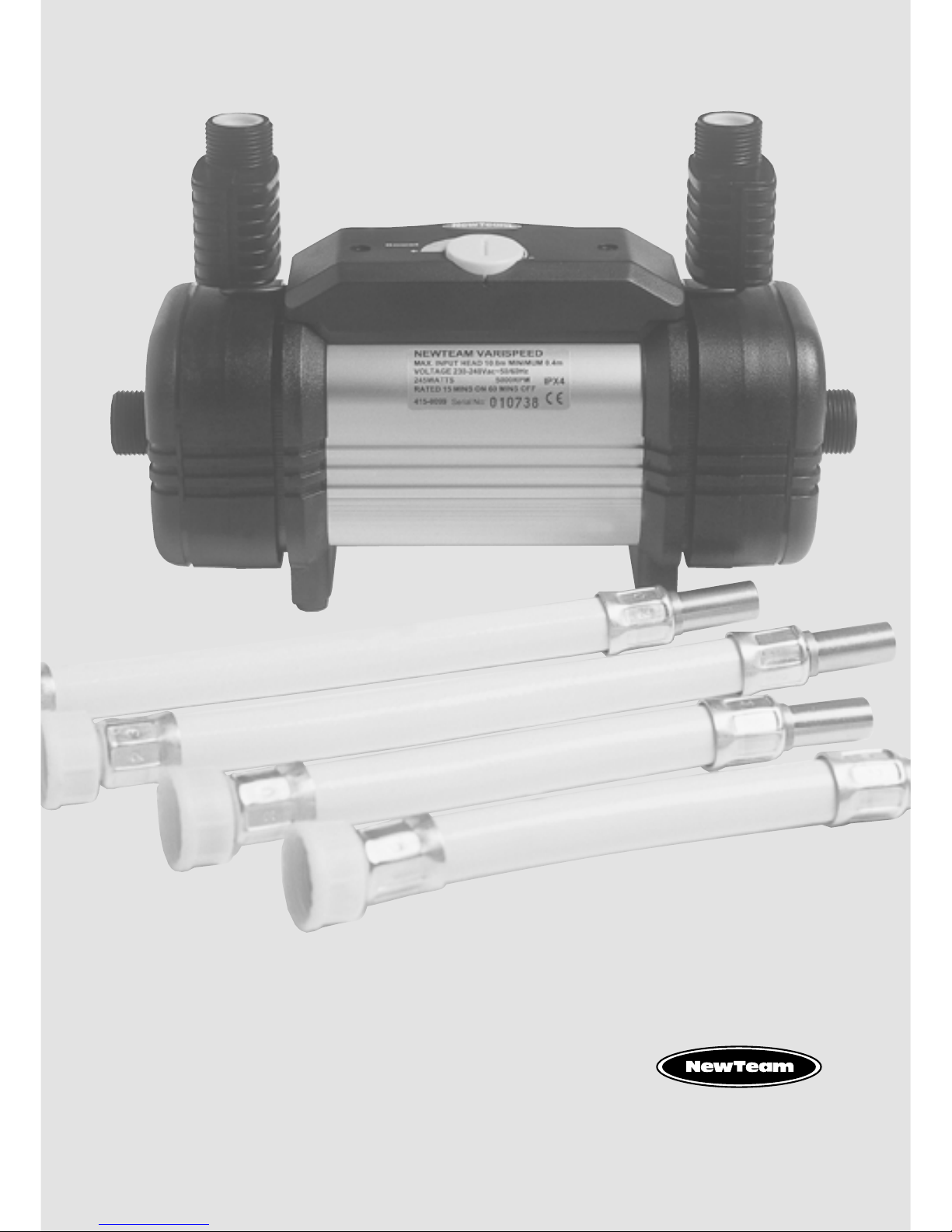
NEWTEAM SHOWER PUMPS
Duraspeed • Duraspeed 2
Varispeed 50 • Varispeed SI • Singlespeed
DEAR INSTALLER WHEN YOU HAVE READ THESE INSTRUCTIONS
PLEASE ENSURE YOU LEAVE THEM WITH THE USER
IN THE EVENT OF ANY QUERY PLEASE CONTACT
THE NEWTEAM CUSTOMER HELPLINE
Tel : 01536 264 012

Product Features
1
NEWTEAM SHOWER PUMPS
NewTeam Shower Pumps
Duraspeed/Duraspeed 2
Varispeed SI
Varispeed 50
Singlespeed
Contents
2
NEWTEAM SHOWER PUMPS
Please read this booklet carefully and ensure the installation is undertaken by
a competent person.
Note: Following the headings in sequence will guide you through the installation
and operation of your NewTeam Shower Pump.
Refer to back cover for Guarantee, Customer Service and Replacement Parts Policy.
In the event of any query regarding installation please contact the NewTeam
Customer Service Department
Tel: 01536 264 012 • Fax: 01536 409 201
E-mail: service@newteam.co.uk • E-mail: spares@newteam.co.uk
In line with our policy of continual product development the specifications may be
varied and product design altered. We reserve the right to depart from the details
given in this manual without prior notice.
PAGES
Installation and Operating Instructions
for NewTeam Shower Pumps
• Duraspeed • Duraspeed 2
• Varispeed 50 • Varispeed SI
• Singlespeed
PLANNING YOUR INSTALLATION 3 - 4
Plumbing
Electrical
FITTING YOUR PUMP 5 - 7
Procedures
Duraspeed & Duraspeed 2
Varispeed SI
Varispeed 50 & Singlespeed
NEGATIVE HEAD OPTIONS 8
COMMISSIONING & 9
TROUBLE SHOOTING 5
SPARE PARTS LISTING 10 - 12
GUARANTEE 13
Planning your Installation
3
NEWTEAM SHOWER PUMPS
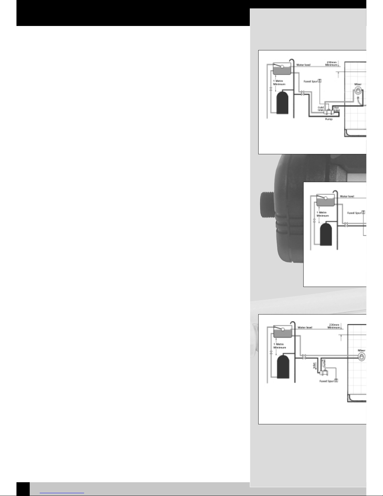
Twin-ended
Shower Booster Pump
DURASPEED, VARISPEED 50, DURASPEED 2
& SINGLESPEED (Fig. 1.)
Twin booster pumps are best installed in the airing cupboard with separate hot and
cold water supplies running to the pump. For correct operation of the shower
pumps both hot and cold water supplies to the unit must be gravity fed, at
nominally equal pressures; cold water from a cold water storage tank and hot water
from a hot water storage cylinder fed from a cold water storage tank.
Single-ended
Shower Booster Pump
VARISPEED SI (Fig. 2.)
Single Booster pumps are best installed after the mixing valve with blended hot
and cold water running to the pump and then onto the handset position. With a
recessed installation, the outlet from the mixer valve can be fed to the inlet of the
single ended pump, and the pump outlet connected to the shower hose, normally
via a shower hose union elbow. See page 4 for gravity hot water boost only.
Plumbing
• We recommend a minimum 115 litres (25 gallon) cold water storage tank, but
please ensure compliance with all water by-laws.
•
Under no circumstances must the pump be connected to the mains cold
water supply.
• Do not use jointing compounds
• Before proceeding with the installation of this unit, it is essential to check that
the handset and all pipework will be a minimum of 230mm (9") below the water
level in the cold water storage tank.
• If your installation does not allow this, you will require a negative head switch.
Contact your supplier or NewTeam Customer Services. If you have not sourced
your negative head switch from NewTeam, please contact NewTeam Customer
Service for a connection block. Please refer to page 9 for details of negative
head installation.
•
Please ensure that the shower pump and mixing valve are not positioned
in areas subjected to freezing conditions.
Fig. 3. Boost of gravity hot only
Fig. 2. Typical Single Pum
Shower Installation
Fig. 1. Typical Twin Pump Shower Installation

Planning your Installation
4
NEWTEAM SHOWER PUMPS
Electrical
IMPORTANT: This appliance must be earthed. This unit should be installed in
accordance with the 16th Edition IEE Wiring Regulations (BS 7671). If in doubt,
consult a qualified electrician.
The pump must be connected to a 230 volt a.c. supply, fused at 3 amps, via double
pole isolator with a contact separation of at least 3mm.
It is recommended that your installation is protected by a residual current device
(RCD) with a trip rating of no more than 30mA
Connections:
All pumps are supplied with a fitted flex.
The colour of the wires in the cable used for final connection of this appliance
may not correspond with the coloured markings identifying the terminals in
your flex outlet; connection at the appliance and the flex outlet should proceed
as follows.
The wire that is coloured blue must be connected to the terminal that is marked with
the letter N, or coloured black.
The wire that is coloured brown must be connected to the terminal that is marked
with the letter L, or coloured red.
The wire that is coloured green/yellow must be connected to the terminal that is
marked with the letter E, or the earth symbol , or coloured green.
The flex fitted to the pumps can only be replaced by NewTeam,
part no. SP-088-0502.
IMPORTANT: WHEN REPLACING FLEX ENSURE THAT THE CONTROL BOX
COVER IS REPLACED WITHOUT DAMAGING THE NEW CABLES. THE CABLE
GROMMET SHOULD BE USED WHERE THE CABLE ENTERS THE BOX.
VARISPEED SI: BOOST OF GRAVITY HOT ONLY (Fig. 3.)
If you are installing a Varispeed SI, where only a gravity feed is available on the hot
supply, the pump can be used to boost the gravity hot supply only. All storage
capacities and pipe connections (as detailed in fig.2) should be followed. The outlet
feed from the pump should then run to the mixer valve or tap position, ensuring that
the minimum head of 230mm to the handset can be achieved.
UNDER NO CIRCUMSTANCES MUST ANY OF THE PUMPS BE CONNECTED TO
THE MAINS WATER SUPPLY .
 Loading...